EP2455930A1 - A display for indicating an operational progress of an apparatus, in particular a household appliance - Google Patents
A display for indicating an operational progress of an apparatus, in particular a household appliance Download PDFInfo
- Publication number
- EP2455930A1 EP2455930A1 EP10014782A EP10014782A EP2455930A1 EP 2455930 A1 EP2455930 A1 EP 2455930A1 EP 10014782 A EP10014782 A EP 10014782A EP 10014782 A EP10014782 A EP 10014782A EP 2455930 A1 EP2455930 A1 EP 2455930A1
- Authority
- EP
- European Patent Office
- Prior art keywords
- light guide
- light
- display according
- sections
- display
- Prior art date
- Legal status (The legal status is an assumption and is not a legal conclusion. Google has not performed a legal analysis and makes no representation as to the accuracy of the status listed.)
- Granted
Links
- 230000000295 complement effect Effects 0.000 claims abstract description 4
- 229920003023 plastic Polymers 0.000 claims description 4
- 230000007423 decrease Effects 0.000 claims description 3
- 239000003086 colorant Substances 0.000 claims description 2
- 230000000694 effects Effects 0.000 description 4
- 238000005562 fading Methods 0.000 description 2
- 238000012986 modification Methods 0.000 description 2
- 230000004048 modification Effects 0.000 description 2
- 230000003287 optical effect Effects 0.000 description 2
- 238000010411 cooking Methods 0.000 description 1
- 238000005034 decoration Methods 0.000 description 1
- 230000003247 decreasing effect Effects 0.000 description 1
- 238000009826 distribution Methods 0.000 description 1
- 239000004973 liquid crystal related substance Substances 0.000 description 1
- 238000004519 manufacturing process Methods 0.000 description 1
- 239000000463 material Substances 0.000 description 1
- 238000000034 method Methods 0.000 description 1
- 238000000926 separation method Methods 0.000 description 1
- 238000003892 spreading Methods 0.000 description 1
- 238000005406 washing Methods 0.000 description 1
Images


Classifications
-
- G—PHYSICS
- G09—EDUCATION; CRYPTOGRAPHY; DISPLAY; ADVERTISING; SEALS
- G09F—DISPLAYING; ADVERTISING; SIGNS; LABELS OR NAME-PLATES; SEALS
- G09F9/00—Indicating arrangements for variable information in which the information is built-up on a support by selection or combination of individual elements
- G09F9/30—Indicating arrangements for variable information in which the information is built-up on a support by selection or combination of individual elements in which the desired character or characters are formed by combining individual elements
- G09F9/305—Indicating arrangements for variable information in which the information is built-up on a support by selection or combination of individual elements in which the desired character or characters are formed by combining individual elements being the ends of optical fibres
-
- A—HUMAN NECESSITIES
- A47—FURNITURE; DOMESTIC ARTICLES OR APPLIANCES; COFFEE MILLS; SPICE MILLS; SUCTION CLEANERS IN GENERAL
- A47L—DOMESTIC WASHING OR CLEANING; SUCTION CLEANERS IN GENERAL
- A47L15/00—Washing or rinsing machines for crockery or tableware
- A47L15/42—Details
- A47L15/4293—Arrangements for programme selection, e.g. control panels; Indication of the selected programme, programme progress or other parameters of the programme, e.g. by using display panels
-
- G—PHYSICS
- G02—OPTICS
- G02B—OPTICAL ELEMENTS, SYSTEMS OR APPARATUS
- G02B6/00—Light guides; Structural details of arrangements comprising light guides and other optical elements, e.g. couplings
- G02B6/0001—Light guides; Structural details of arrangements comprising light guides and other optical elements, e.g. couplings specially adapted for lighting devices or systems
- G02B6/0005—Light guides; Structural details of arrangements comprising light guides and other optical elements, e.g. couplings specially adapted for lighting devices or systems the light guides being of the fibre type
- G02B6/0008—Light guides; Structural details of arrangements comprising light guides and other optical elements, e.g. couplings specially adapted for lighting devices or systems the light guides being of the fibre type the light being emitted at the end of the fibre
-
- G—PHYSICS
- G09—EDUCATION; CRYPTOGRAPHY; DISPLAY; ADVERTISING; SEALS
- G09F—DISPLAYING; ADVERTISING; SIGNS; LABELS OR NAME-PLATES; SEALS
- G09F23/00—Advertising on or in specific articles, e.g. ashtrays, letter-boxes
- G09F23/0058—Advertising on or in specific articles, e.g. ashtrays, letter-boxes on electrical household appliances, e.g. on a dishwasher, a washing machine or a refrigerator
Definitions
- the present invention relates to a display for indicating an operational progress of an apparatus, in particular of a household appliance, as well as to an apparatus.
- the operations of many apparatus are performed according to a predetermined and/or adjustable program.
- the operations of household appliances like washing machines, laundry driers or dishwashers, are performed automatically, after the user has started the procedure. It would be advantageous to inform the user about the progress of the operation by simply means.
- DE 103 37 043 A1 discloses an analogous display for indicating the operational progress of a household appliance.
- the display includes a plurality of light emitting diodes arranged in series. At the start of the operation the first light emitting diode is activated. Then the neighbouring light emitting diodes are consecutively activated. The number of activated light emitting diodes represents the elapsed time of the operation.
- DE 101 44 668 A1 discloses a display for indicating the speed of a rotating component of a household appliance.
- the display includes a closed light-band with a plurality of light emitting diodes.
- the light emitting diodes flash, so that a rotating light signal is generated.
- the rotating speed of the light signal is proportional to the actual speed of the rotating component.
- the light signal is further used for indicating the operational progress of the household appliance.
- EP 1 417 440 A1 discloses a cooking appliance with an optical indicator light.
- the colour and/or the colour intensity of the indicator light are in ratio to the temperature in the oven cavity.
- the object of the present invention is achieved by the display according to claim 1.
- the present invention relates a display for indicating an operational progress of an apparatus, in particular of a household appliance, wherein:
- the core of the present invention is the structure of the light guide and the compatible front casing.
- the single sections of said light guide are separated from each other, so that the light from one light emitting diode is only spreading in the corresponding section within the light guide. This contributes to the visibility of the display from a distance.
- the light guide can be a light guiding device, which can preferably consist of a single piece or comprise a plurality of single light guides.
- the light guide is made of transparent plastics.
- Transparent plastic is a cheap material.
- the light guide may be formed as a single-piece part.
- the light guide as the single-piece part simplifies the production of the display.
- the sections of the light guide are arranged in series. This allows a clear animation indicating the progress of the operation.
- the sections of the light guide may be arranged circularly.
- At least one section of the light guide has a changing depth, wherein said depth extends parallel to a main axis of the light cone from the corresponding light emitting diode.
- the depth of the at least one section decreases with the distance from the corresponding light emitting diode. This contributes to the light fading effect.
- at least one of the sections at the ends of the light guide has a changing depth.
- the intensities of the light emitting diodes are separately controlled or controllable. This allows various animations for indicating the progress of the operation and/or the status of the apparatus.
- the light emitting diodes may be activated by a steady burning light or by a flashing light.
- the colours of the light emitting diodes are separately controlled or controllable. This allows additional animations for indicating the status of the apparatus and/or the progress of the operation.
- the front casing may comprise walls enclosing at least partially the light guide perpendicular to the main axis of the light cone from the light emitting diodes.
- the front casing comprises a plurality of intermediate walls arranged or arrangable between neighbouring sections of the light guide. This prevents a light distribution to the neighbouring sections of the light guide.
- neighbouring sections of the light guide are connected by connecting elements arranged beyond the light cone of the corresponding light emitting diodes.
- the apparatus is a dishwasher or an oven.
- the invention relates to an apparatus, in particular a household appliance, wherein the apparatus and/or the household appliance is preferably an oven or dishwasher, with a display according to the invention.
- FIG 1 illustrates a perspective sectional view of a display according to a preferred embodiment of the present invention.
- the display is provided for indicating the progress and/or the status of the operation of an apparatus, in particular a household appliance.
- the display includes a front casing 10 and a rear casing 12. An open front side of the rear casing 12 is covered by the front casing 10.
- a circuit board 14 is arranged between the front casing 10 and the rear casing 12.
- a screen 16 is arranged within a rectangular opening in the front casing 10. In this example, the screen 16 is a liquid crystal display (LCD) screen.
- LCD liquid crystal display
- the front casing 10 comprises a horizontal slot stretching across the substantially whole broadness of said front casing 10.
- the slot includes a top wall 18 and a bottom wall 20, wherein said slot projects forwardly.
- the slot comprises a plurality of intermediate walls 22, so that the slot is subdivided into a plurality of cells arranged side by side. In this example, the slot is arranged in the lower portion of the front casing 10.
- a light guide 24 is arranged within the slot.
- the light guide 24 is formed complementary to the inner space of the slot.
- the light guide 24 fills the slot and the cells.
- the light guide 24 is subdivided into a plurality of sections 26 corresponding with the cells of the slots.
- the both sections 26 at the ends of the light guide 24 are broader than the other sections 26. In this example, the sections 26 at the ends are about four or five times broader than the other sections 26.
- a plurality of light emitting diodes 28 is arranged on the circuit board 14 along a horizontal line.
- Each light emitting diode (LED) 28 corresponds with one of the sections 26 of the light guide 24.
- the light emitting diode 28 is arranged behind the corresponding section 26 of the light guide 24.
- one section 26 of the light guide 24 may correspond with several light emitting diodes 28.
- Each light emitting diode (LED) 28 is separately controlled.
- the intensity of the emitted light from the light emitting diode 28 is controllable.
- the colour of the emitted light from the light emitting diode 28 may be controllable.
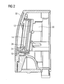
- FIG 2 illustrates a sectional side view of the display according to the preferred embodiment of the present invention.
- the display is integrated within a housing 30 of a household appliance.
- a front panel 32 is arranged at the front side of said housing 30 and covers the display.
- the front panel 32 is at least partially transparent.
- the circuit board 14 is arranged between the front casing 10 and the rear casing 12.
- the light emitting diodes 28 are attached at the circuit board 14 and arranged behind the light guide 24.
- the light guide 24 is made of transparent plastics. Further, the light guide 24 is made in one mould. A rear surface of the light guide 24 is in front of the light emitting diodes 28. A front surface of the light guide 24 is behind the front panel 32.
- the light emitted from the light emitting diodes 28 is spread through the light guide 24.
- the light guide 24 reflects and distributes the light received at the rear surface to the front surface of the light guide 24.
- the geometric arrangement of the housing 30, the front casing 10, the rear casing 12, the intermediate walls 22 and the sections 26 prevent that light from one cell is reflected into one of the neighbouring cells.
- FIG 3 illustrates a perspective view of the light guide 24 for the display according to the preferred embodiment of the present invention.
- FIG 3 clarifies the geometric structure of the light guide 24.
- the light guide 24 is subdivided into the plurality of sections 26.
- the both sections 26 at the ends of the light guide 24 are considerably broader than the other sections 26.
- Said sections 26 at the ends of the light guide 24 provide an aesthetic light fade effect.
- the depth of the sections 26 at the ends of the light guide 24 decreases outwardly. Said decreasing depth allows the light fade effect.
- FIG 4 illustrates a perspective view of the light guide 24 and the circuit board 14 for the display according to the preferred embodiment of the present invention.
- FIG 4 clarifies the arrangement of the light guide 24 in view of the circuit board 14.
- the light emitting diodes 28 are attached near a lower border of the circuit board 14.
- the light emitting diodes 28 are arranged between the light guide 24 and the circuit board 14.
- the arrangement of the light emitting diodes 28 and the geometric structure of the light guide 24 allow the optical separation between the cells.
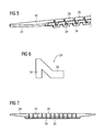
- FIG 5 illustrates a perspective view of a part of the light guide 24 for the display according to the preferred embodiment of the present invention.
- FIG 5 clarifies that the rear side of the light guide 24 has the form of a meander.
- the higher portions of said meander are the rear surfaces of the sections 26.
- the lower portions of the meander are connecting elements 34 between said sections 26. This structure prevents that light from one section 26 is reflected or distributed into a neighbouring section 26.
- FIG 6 illustrates a sectional side view of the light guide 24 for the display according to the preferred embodiment of the present invention.
- the sectional side view of the light guide 24 shows that effectively no light may be radiated between the neighbouring sections 26.
- FIG 7 illustrates a top view of the light guide 24 for the display according to the preferred embodiment of the present invention.
- FIG 7 clarifies the big depth of the sections 26 and the relative small depth of the connecting elements 34.
- a first light emitting diode 28 in the series is activated. Then the neighbouring light emitting diodes 28 are consecutively activated.
- the number of activated light emitting diodes 28 represents the elapsed time of the operation.
- a light emitting diode 28 in the centre of the series is activated. Then the outwardly neighbouring light emitting diodes 28 are consecutively activated, so that the light signal becomes broader by the progress of the operation.
- the light signals of the above examples may be programmed as a so-called running light.
- the light from the light emitting diodes 28 can also be used to highlight a symbol, a number and/or a text printed at the front panel 32. Said symbol, number or text may give certain information to the user.
Landscapes
- Physics & Mathematics (AREA)
- General Physics & Mathematics (AREA)
- Engineering & Computer Science (AREA)
- Theoretical Computer Science (AREA)
- Optics & Photonics (AREA)
- Illuminated Signs And Luminous Advertising (AREA)
- Induction Heating Cooking Devices (AREA)
- Cookers (AREA)
Abstract
- the display includes at least one light guide (24) subdivided into a plurality of sections (26),
- the display includes a plurality of light sources, preferably a plurality of light emitting diodes (28), arranged according to a predetermined scheme,
- the light sources (28) are separately controlled or controllable,
- each section (26) of the plurality of sections corresponds with at least one light source (28),
- the display includes at least one casing (10), especially at least one front casing (10), for receiving the light guide (24), and
- the casing (10) is at least partially complementary to the light guide (24), preferably in order to prevent a light propagation between the sections (26) of the light guide (24).
Description
- The present invention relates to a display for indicating an operational progress of an apparatus, in particular of a household appliance, as well as to an apparatus.
- The operations of many apparatus are performed according to a predetermined and/or adjustable program. The operations of household appliances, like washing machines, laundry driers or dishwashers, are performed automatically, after the user has started the procedure. It would be advantageous to inform the user about the progress of the operation by simply means.
-
DE 103 37 043 A1 discloses an analogous display for indicating the operational progress of a household appliance. The display includes a plurality of light emitting diodes arranged in series. At the start of the operation the first light emitting diode is activated. Then the neighbouring light emitting diodes are consecutively activated. The number of activated light emitting diodes represents the elapsed time of the operation. -
DE 101 44 668 A1 discloses a display for indicating the speed of a rotating component of a household appliance. The display includes a closed light-band with a plurality of light emitting diodes. The light emitting diodes flash, so that a rotating light signal is generated. The rotating speed of the light signal is proportional to the actual speed of the rotating component. The light signal is further used for indicating the operational progress of the household appliance. -
EP 1 417 440 A1 discloses a cooking appliance with an optical indicator light. The colour and/or the colour intensity of the indicator light are in ratio to the temperature in the oven cavity. - It is an object of the present invention to provide a display for indicating an operational progress of an apparatus, wherein the display is visible from a distance and has an aesthetic decoration and low complexity.
- The object of the present invention is achieved by the display according to claim 1.
- The present invention relates a display for indicating an operational progress of an apparatus, in particular of a household appliance, wherein:
- the display includes at least one light guide subdivided into a plurality of sections,
- the display includes a plurality of light sources, preferably a plurality of light emitting diodes, arranged according to a predetermined scheme,
- the light sources are separately controlled or controllable,
- each section of the plurality of sections corresponds with at least one light source,
- the display includes at least one casing, especially at least one front casing, for receiving the light guide, and
- the casing is at least partially complementary to the light guide, preferably in order to prevent a light propagation between the sections of the light guide.
- The core of the present invention is the structure of the light guide and the compatible front casing. The single sections of said light guide are separated from each other, so that the light from one light emitting diode is only spreading in the corresponding section within the light guide. This contributes to the visibility of the display from a distance.
- In particular, the light guide can be a light guiding device, which can preferably consist of a single piece or comprise a plurality of single light guides.
- In particular, the light guide is made of transparent plastics. Transparent plastic is a cheap material.
- Further, the light guide may be formed as a single-piece part. The light guide as the single-piece part simplifies the production of the display.
- For example, the sections of the light guide are arranged in series. This allows a clear animation indicating the progress of the operation. According to a further example, the sections of the light guide may be arranged circularly.
- Preferably, at least one section of the light guide has a changing depth, wherein said depth extends parallel to a main axis of the light cone from the corresponding light emitting diode. This structure allows a light fading effect with an advantageous aesthetic.
- In particular, the depth of the at least one section decreases with the distance from the corresponding light emitting diode. This contributes to the light fading effect. For example, at least one of the sections at the ends of the light guide has a changing depth.
- Preferably, the intensities of the light emitting diodes are separately controlled or controllable. This allows various animations for indicating the progress of the operation and/or the status of the apparatus. The light emitting diodes may be activated by a steady burning light or by a flashing light.
- In a similar way, the colours of the light emitting diodes are separately controlled or controllable. This allows additional animations for indicating the status of the apparatus and/or the progress of the operation.
- Further, the front casing may comprise walls enclosing at least partially the light guide perpendicular to the main axis of the light cone from the light emitting diodes.
- In particular, the front casing comprises a plurality of intermediate walls arranged or arrangable between neighbouring sections of the light guide. This prevents a light distribution to the neighbouring sections of the light guide.
- Preferably, neighbouring sections of the light guide are connected by connecting elements arranged beyond the light cone of the corresponding light emitting diodes.
- Preferably, the apparatus is a dishwasher or an oven.
- Furthermore, the invention relates to an apparatus, in particular a household appliance, wherein the apparatus and/or the household appliance is preferably an oven or dishwasher, with a display according to the invention.
- Novel and inventive features of the present invention are set forth in the appended claims.
- The present invention will be described in further detail with reference to the accompanied drawings, in which
- FIG 1
- illustrates a perspective sectional view of a display according to a preferred embodiment of the present invention,
- FIG 2
- illustrates a sectional side view of the display according to the preferred embodiment of the present invention,
- FIG 3
- illustrates a perspective view of a light guide for the display according to the preferred embodiment of the present invention,
- FIG 4
- illustrates a perspective view of the light guide and a circuit board for the display according to the preferred embodiment of the present invention,
- FIG 5
- illustrates a perspective view of a part of the light guide for the display according to the preferred embodiment of the present invention,
- FIG 6
- illustrates a sectional side view of the light guide for the display according to the preferred embodiment of the present invention, and
- FIG 7
- illustrates a top view of the light guide for the display according to the preferred embodiment of the present invention.
-
FIG 1 illustrates a perspective sectional view of a display according to a preferred embodiment of the present invention. The display is provided for indicating the progress and/or the status of the operation of an apparatus, in particular a household appliance. - The display includes a
front casing 10 and arear casing 12. An open front side of therear casing 12 is covered by thefront casing 10. Acircuit board 14 is arranged between thefront casing 10 and therear casing 12. Ascreen 16 is arranged within a rectangular opening in thefront casing 10. In this example, thescreen 16 is a liquid crystal display (LCD) screen. - The
front casing 10 comprises a horizontal slot stretching across the substantially whole broadness of saidfront casing 10. The slot includes atop wall 18 and abottom wall 20, wherein said slot projects forwardly. The slot comprises a plurality ofintermediate walls 22, so that the slot is subdivided into a plurality of cells arranged side by side. In this example, the slot is arranged in the lower portion of thefront casing 10. - A
light guide 24 is arranged within the slot. Thelight guide 24 is formed complementary to the inner space of the slot. Thus, thelight guide 24 fills the slot and the cells. Thelight guide 24 is subdivided into a plurality ofsections 26 corresponding with the cells of the slots. The bothsections 26 at the ends of thelight guide 24 are broader than theother sections 26. In this example, thesections 26 at the ends are about four or five times broader than theother sections 26. - A plurality of
light emitting diodes 28 is arranged on thecircuit board 14 along a horizontal line. Each light emitting diode (LED) 28 corresponds with one of thesections 26 of thelight guide 24. Thelight emitting diode 28 is arranged behind the correspondingsection 26 of thelight guide 24. Alternatively, onesection 26 of thelight guide 24 may correspond with severallight emitting diodes 28. - Each light emitting diode (LED) 28 is separately controlled. In particular, the intensity of the emitted light from the
light emitting diode 28 is controllable. Further, the colour of the emitted light from thelight emitting diode 28 may be controllable. -
FIG 2 illustrates a sectional side view of the display according to the preferred embodiment of the present invention. The display is integrated within ahousing 30 of a household appliance. Afront panel 32 is arranged at the front side of saidhousing 30 and covers the display. Thefront panel 32 is at least partially transparent. - The
circuit board 14 is arranged between thefront casing 10 and therear casing 12. Thelight emitting diodes 28 are attached at thecircuit board 14 and arranged behind thelight guide 24. Thelight guide 24 is made of transparent plastics. Further, thelight guide 24 is made in one mould. A rear surface of thelight guide 24 is in front of thelight emitting diodes 28. A front surface of thelight guide 24 is behind thefront panel 32. - The light emitted from the
light emitting diodes 28 is spread through thelight guide 24. Thelight guide 24 reflects and distributes the light received at the rear surface to the front surface of thelight guide 24. The geometric arrangement of thehousing 30, thefront casing 10, therear casing 12, theintermediate walls 22 and thesections 26 prevent that light from one cell is reflected into one of the neighbouring cells. -
FIG 3 illustrates a perspective view of thelight guide 24 for the display according to the preferred embodiment of the present invention.FIG 3 clarifies the geometric structure of thelight guide 24. - The
light guide 24 is subdivided into the plurality ofsections 26. The bothsections 26 at the ends of thelight guide 24 are considerably broader than theother sections 26. Saidsections 26 at the ends of thelight guide 24 provide an aesthetic light fade effect. The depth of thesections 26 at the ends of thelight guide 24 decreases outwardly. Said decreasing depth allows the light fade effect. -
FIG 4 illustrates a perspective view of thelight guide 24 and thecircuit board 14 for the display according to the preferred embodiment of the present invention.FIG 4 clarifies the arrangement of thelight guide 24 in view of thecircuit board 14. - The
light emitting diodes 28 are attached near a lower border of thecircuit board 14. Thelight emitting diodes 28 are arranged between thelight guide 24 and thecircuit board 14. The arrangement of thelight emitting diodes 28 and the geometric structure of thelight guide 24 allow the optical separation between the cells. -
FIG 5 illustrates a perspective view of a part of thelight guide 24 for the display according to the preferred embodiment of the present invention.FIG 5 clarifies that the rear side of thelight guide 24 has the form of a meander. The higher portions of said meander are the rear surfaces of thesections 26. The lower portions of the meander are connectingelements 34 between saidsections 26. This structure prevents that light from onesection 26 is reflected or distributed into a neighbouringsection 26. -
FIG 6 illustrates a sectional side view of thelight guide 24 for the display according to the preferred embodiment of the present invention. The sectional side view of thelight guide 24 shows that effectively no light may be radiated between the neighbouringsections 26. -
FIG 7 illustrates a top view of thelight guide 24 for the display according to the preferred embodiment of the present invention.FIG 7 clarifies the big depth of thesections 26 and the relative small depth of the connectingelements 34. - For example, at the start of the operation a first
light emitting diode 28 in the series is activated. Then the neighbouringlight emitting diodes 28 are consecutively activated. The number of activatedlight emitting diodes 28 represents the elapsed time of the operation. - Further, at the start of the operation a
light emitting diode 28 in the centre of the series is activated. Then the outwardly neighbouring light emittingdiodes 28 are consecutively activated, so that the light signal becomes broader by the progress of the operation. - Alternatively, the light signals of the above examples may be programmed as a so-called running light.
- At last, the light from the
light emitting diodes 28 can also be used to highlight a symbol, a number and/or a text printed at thefront panel 32. Said symbol, number or text may give certain information to the user. - Although illustrative embodiments of the present invention has been described herein with reference to the accompanying drawings, it is to be understood that the present invention is not limited to that precise embodiment, and that various other changes and modifications may be affected therein by one skilled in the art without departing from the scope or spirit of the invention. All such changes and modifications are intended to be included within the scope of the invention as defined by the appended claims.
-
- 10
- front casing
- 12
- rear casing
- 14
- circuit board
- 16
- screen
- 18
- top wall
- 20
- bottom wall
- 22
- intermediate wall
- 24
- light guide
- 26
- section
- 28
- light emitting diode
- 30
- housing
- 32
- front panel
- 34
- connecting element
Claims (14)
- A display for indicating an operational progress of an apparatus, in particular of a household appliance, wherein:- the display includes at least one light guide (24) subdivided into a plurality of sections (26),- the display includes a plurality of light sources, preferably a plurality of light emitting diodes (28), arranged according to a predetermined scheme,- the light sources (28) are separately controlled or controllable,- each section (26) of the plurality of sections corresponds with at least one light source (28),- the display includes at least one casing (10), especially at least one front casing (10), for receiving the light guide (24), and- the casing (10) is at least partially complementary to the light guide (24), preferably in order to prevent a light propagation between the sections (26) of the light guide (24).
- The display according to claim 1,
characterized in, that
the light guide (24) is made of transparent plastics. - The display according to claim 1 or 2,
characterized in, that
the light guide (24) is formed as a single-piece part. - The display according to any one of the preceding claims,
characterized in, that
the sections (26) of the light guide (24) are arranged in series. - The display according to any one of the preceding claims,
characterized in, that
at least one section (26) of the light guide (24) has a changing depth, wherein said depth extends parallel to a main axis of the light cone from the corresponding light emitting diode (28). - The display according to claim 5,
characterized in, that
the depth of the at least one section (26) decreases with the distance from the corresponding light emitting diode (28). - The display according to claim 5 or 6,
characterized in, that
at least one of the sections (26) at the ends of the light guide (24) have a changing depth. - The display according to any one of the preceding claims,
characterized in, that
the intensities of the light emitting diodes (28) are separately controlled or controllable. - The display according to any one of the preceding claims,
characterized in, that
the colours of the light emitting diodes (28) are separately controlled or controllable. - The display according to any one of the preceding claims,
characterized in, that
the front casing (10) comprises walls (18, 20) enclosing at least partially the light guide (24) perpendicular to the main axis of the light cone from the light emitting diodes (28). - The display according to any one of the preceding claims,
characterized in, that
the front casing (10) comprises a plurality of intermediate walls (22) arranged or arrangable between neighbouring sections (26) of the light guide (24). - The display according to any one of the preceding claims,
characterized in, that
neighbouring sections (26) of the light guide (24) are connected by connecting elements (34) arranged beyond the light cone of the corresponding light emitting diodes (28). - The display according to any one of the preceding claims,
characterized in, that
the apparatus is a dishwasher or an oven. - Apparatus, in particular a household appliance, wherein the apparatus and/or the household appliance is preferably an oven or dishwasher,
with a display according to any one of the preceding claims.
Priority Applications (2)
| Application Number | Priority Date | Filing Date | Title |
|---|---|---|---|
| EP10014782.6A EP2455930B1 (en) | 2010-11-19 | 2010-11-19 | A display for indicating an operational progress of an apparatus, in particular a household appliance |
| EP13184148.8A EP2674931A1 (en) | 2010-11-19 | 2010-11-19 | A display for indicating an operational progress of an apparatus, in particular a household appliance |
Applications Claiming Priority (1)
| Application Number | Priority Date | Filing Date | Title |
|---|---|---|---|
| EP10014782.6A EP2455930B1 (en) | 2010-11-19 | 2010-11-19 | A display for indicating an operational progress of an apparatus, in particular a household appliance |
Publications (2)
| Publication Number | Publication Date |
|---|---|
| EP2455930A1 true EP2455930A1 (en) | 2012-05-23 |
| EP2455930B1 EP2455930B1 (en) | 2013-09-25 |
Family
ID=43797711
Family Applications (2)
| Application Number | Title | Priority Date | Filing Date |
|---|---|---|---|
| EP10014782.6A Not-in-force EP2455930B1 (en) | 2010-11-19 | 2010-11-19 | A display for indicating an operational progress of an apparatus, in particular a household appliance |
| EP13184148.8A Withdrawn EP2674931A1 (en) | 2010-11-19 | 2010-11-19 | A display for indicating an operational progress of an apparatus, in particular a household appliance |
Family Applications After (1)
| Application Number | Title | Priority Date | Filing Date |
|---|---|---|---|
| EP13184148.8A Withdrawn EP2674931A1 (en) | 2010-11-19 | 2010-11-19 | A display for indicating an operational progress of an apparatus, in particular a household appliance |
Country Status (1)
| Country | Link |
|---|---|
| EP (2) | EP2455930B1 (en) |
Cited By (5)
| Publication number | Priority date | Publication date | Assignee | Title |
|---|---|---|---|---|
| EP2837725A1 (en) * | 2013-08-13 | 2015-02-18 | Electrolux Appliances Aktiebolag | Laundry treatment device having a control panel assembly |
| CN104766541A (en) * | 2014-01-06 | 2015-07-08 | 三星电子株式会社 | Home appliance having display unit |
| WO2015185634A1 (en) * | 2014-06-06 | 2015-12-10 | BSH Hausgeräte GmbH | Domestic appliance with a visual display of method steps proceeding therein, and method for operating said domestic appliance |
| EP3187641A4 (en) * | 2014-08-26 | 2018-05-09 | Foshan Haier Drum Washing Machine Co. Ltd. | Washing machine having breathing light set and control method for the washing machine |
| EP4579126A1 (en) * | 2023-12-29 | 2025-07-02 | BSH Hausgeräte GmbH | Display unit and household appliance having display unit |
Families Citing this family (3)
| Publication number | Priority date | Publication date | Assignee | Title |
|---|---|---|---|---|
| USD825584S1 (en) | 2017-03-29 | 2018-08-14 | Becton, Dickinson And Company | Display screen or portion thereof with transitional graphical user interface |
| DE112017007282B4 (en) | 2017-04-19 | 2025-01-30 | Ford Global Technologies, Llc | Providing trip status in a vehicle |
| US11006812B2 (en) * | 2018-10-11 | 2021-05-18 | Haier Us Appliance Solutions, Inc. | Status indicator and lighting assembly for an appliance door |
Citations (8)
| Publication number | Priority date | Publication date | Assignee | Title |
|---|---|---|---|---|
| US5349504A (en) * | 1993-07-12 | 1994-09-20 | Dialight Corporation | Multi-level lightpipe design for SMD LEDs |
| US5915060A (en) * | 1997-09-17 | 1999-06-22 | Aiwa Co., Ltd. | Light pipe array |
| US5938324A (en) * | 1996-10-07 | 1999-08-17 | Cisco Technology, Inc. | Light pipe |
| US5988842A (en) * | 1996-10-04 | 1999-11-23 | Johnsen; Roger T. | Apparatus for showing light at a distance from a light source |
| US6463204B1 (en) * | 1998-12-18 | 2002-10-08 | Fujitsu Network Communications, Inc. | Modular lightpipe system |
| DE10144668A1 (en) | 2001-09-11 | 2003-03-27 | Bsh Bosch Siemens Hausgeraete | Display on e.g. washing and drying machines, includes strip of lights flashing to show rotation, speed and optionally course of program execution |
| EP1417440A1 (en) | 2001-08-08 | 2004-05-12 | BSH Bosch und Siemens Hausgeräte GmbH | Cooking device |
| DE10337043A1 (en) | 2003-08-12 | 2005-03-17 | BSH Bosch und Siemens Hausgeräte GmbH | Analogue program sequence display for domestic equipment e.g. for washing machine, uses adjacent light emitting diodes (LEDs) for switching time order of sequential program |
-
2010
- 2010-11-19 EP EP10014782.6A patent/EP2455930B1/en not_active Not-in-force
- 2010-11-19 EP EP13184148.8A patent/EP2674931A1/en not_active Withdrawn
Patent Citations (8)
| Publication number | Priority date | Publication date | Assignee | Title |
|---|---|---|---|---|
| US5349504A (en) * | 1993-07-12 | 1994-09-20 | Dialight Corporation | Multi-level lightpipe design for SMD LEDs |
| US5988842A (en) * | 1996-10-04 | 1999-11-23 | Johnsen; Roger T. | Apparatus for showing light at a distance from a light source |
| US5938324A (en) * | 1996-10-07 | 1999-08-17 | Cisco Technology, Inc. | Light pipe |
| US5915060A (en) * | 1997-09-17 | 1999-06-22 | Aiwa Co., Ltd. | Light pipe array |
| US6463204B1 (en) * | 1998-12-18 | 2002-10-08 | Fujitsu Network Communications, Inc. | Modular lightpipe system |
| EP1417440A1 (en) | 2001-08-08 | 2004-05-12 | BSH Bosch und Siemens Hausgeräte GmbH | Cooking device |
| DE10144668A1 (en) | 2001-09-11 | 2003-03-27 | Bsh Bosch Siemens Hausgeraete | Display on e.g. washing and drying machines, includes strip of lights flashing to show rotation, speed and optionally course of program execution |
| DE10337043A1 (en) | 2003-08-12 | 2005-03-17 | BSH Bosch und Siemens Hausgeräte GmbH | Analogue program sequence display for domestic equipment e.g. for washing machine, uses adjacent light emitting diodes (LEDs) for switching time order of sequential program |
Cited By (11)
| Publication number | Priority date | Publication date | Assignee | Title |
|---|---|---|---|---|
| EP2837725A1 (en) * | 2013-08-13 | 2015-02-18 | Electrolux Appliances Aktiebolag | Laundry treatment device having a control panel assembly |
| CN104766541A (en) * | 2014-01-06 | 2015-07-08 | 三星电子株式会社 | Home appliance having display unit |
| EP2893864A1 (en) * | 2014-01-06 | 2015-07-15 | Samsung Electronics Co., Ltd | Home appliance having display unit |
| CN104766541B (en) * | 2014-01-06 | 2019-02-05 | 三星电子株式会社 | household appliances |
| WO2015185634A1 (en) * | 2014-06-06 | 2015-12-10 | BSH Hausgeräte GmbH | Domestic appliance with a visual display of method steps proceeding therein, and method for operating said domestic appliance |
| CN106460293A (en) * | 2014-06-06 | 2017-02-22 | Bsh家用电器有限公司 | Domestic appliance with visual display of method steps carried out therein and method for operating the same |
| RU2658257C1 (en) * | 2014-06-06 | 2018-06-19 | Бсх Хаусгерете Гмбх | Household appliance with visualization of working stages and method of work of household appliances |
| CN106460293B (en) * | 2014-06-06 | 2019-05-17 | Bsh家用电器有限公司 | Household appliance with visual display of method steps performed therein and method for operating the same |
| EP3187641A4 (en) * | 2014-08-26 | 2018-05-09 | Foshan Haier Drum Washing Machine Co. Ltd. | Washing machine having breathing light set and control method for the washing machine |
| EP4579126A1 (en) * | 2023-12-29 | 2025-07-02 | BSH Hausgeräte GmbH | Display unit and household appliance having display unit |
| US12468085B2 (en) | 2023-12-29 | 2025-11-11 | BSH Hausgeräte GmbH | Display unit and household appliance having a display unit |
Also Published As
| Publication number | Publication date |
|---|---|
| EP2674931A1 (en) | 2013-12-18 |
| EP2455930B1 (en) | 2013-09-25 |
Similar Documents
| Publication | Publication Date | Title |
|---|---|---|
| EP2455930B1 (en) | A display for indicating an operational progress of an apparatus, in particular a household appliance | |
| EP2650422B1 (en) | Control panel assembly and washing machine having the same | |
| US8810423B2 (en) | Integrated operation display device | |
| CN101878496B (en) | Light emitting diode display module set and washing device comprising the same | |
| US9607792B2 (en) | Knob assemblies with encoder-controlled illumination | |
| US9080272B2 (en) | Washing machine | |
| EP3043131A1 (en) | Appliance having a human-machine interface and illuminated handle recess | |
| KR20170141241A (en) | washer | |
| EP4119873B1 (en) | Home appliance | |
| EP2394556A2 (en) | Built-in dishwasher | |
| RU2676056C2 (en) | Display device and home appliance having such display device | |
| JP5938319B2 (en) | Game machine | |
| WO2012041765A1 (en) | A display unit for electrical domestic appliances | |
| CN114711698A (en) | Dishwasher with a door handle and at least one light element | |
| CN110246434A (en) | Household appliance with display device | |
| RU2739301C1 (en) | Linen care device with indicator element | |
| EP4179950A1 (en) | Home appliance | |
| CN104715697A (en) | Electric home appliance | |
| EP2307808B1 (en) | Kitchen oven | |
| JP2018013304A (en) | Display device and refrigerator including the same | |
| CN209202826U (en) | Cooking apparatus | |
| US9982866B2 (en) | Console assembly with integrated light reflector cups | |
| EP3089644B1 (en) | Dishwasher | |
| CN109154443A (en) | Household appliance for cooking food in an outer part displaying optical information | |
| CN218153791U (en) | Household electrical appliance |
Legal Events
| Date | Code | Title | Description |
|---|---|---|---|
| PUAI | Public reference made under article 153(3) epc to a published international application that has entered the european phase |
Free format text: ORIGINAL CODE: 0009012 |
|
| 17P | Request for examination filed |
Effective date: 20110513 |
|
| AK | Designated contracting states |
Kind code of ref document: A1 Designated state(s): AL AT BE BG CH CY CZ DE DK EE ES FI FR GB GR HR HU IE IS IT LI LT LU LV MC MK MT NL NO PL PT RO RS SE SI SK SM TR |
|
| AX | Request for extension of the european patent |
Extension state: BA ME |
|
| GRAP | Despatch of communication of intention to grant a patent |
Free format text: ORIGINAL CODE: EPIDOSNIGR1 |
|
| RIC1 | Information provided on ipc code assigned before grant |
Ipc: G09F 9/305 20060101AFI20130228BHEP Ipc: A47L 15/42 20060101ALI20130228BHEP Ipc: G02B 6/00 20060101ALI20130228BHEP Ipc: D06F 39/00 20060101ALI20130228BHEP |
|
| RIC1 | Information provided on ipc code assigned before grant |
Ipc: A47L 15/42 20060101ALI20130307BHEP Ipc: G09F 9/305 20060101AFI20130307BHEP Ipc: G02B 6/00 20060101ALI20130307BHEP Ipc: G09F 23/00 20060101ALI20130307BHEP Ipc: D06F 39/00 20060101ALI20130307BHEP |
|
| INTG | Intention to grant announced |
Effective date: 20130403 |
|
| GRAS | Grant fee paid |
Free format text: ORIGINAL CODE: EPIDOSNIGR3 |
|
| GRAA | (expected) grant |
Free format text: ORIGINAL CODE: 0009210 |
|
| AK | Designated contracting states |
Kind code of ref document: B1 Designated state(s): AL AT BE BG CH CY CZ DE DK EE ES FI FR GB GR HR HU IE IS IT LI LT LU LV MC MK MT NL NO PL PT RO RS SE SI SK SM TR |
|
| REG | Reference to a national code |
Ref country code: GB Ref legal event code: FG4D |
|
| REG | Reference to a national code |
Ref country code: CH Ref legal event code: EP |
|
| REG | Reference to a national code |
Ref country code: AT Ref legal event code: REF Ref document number: 633983 Country of ref document: AT Kind code of ref document: T Effective date: 20131015 |
|
| REG | Reference to a national code |
Ref country code: IE Ref legal event code: FG4D |
|
| REG | Reference to a national code |
Ref country code: DE Ref legal event code: R096 Ref document number: 602010010481 Country of ref document: DE Effective date: 20131121 |
|
| PG25 | Lapsed in a contracting state [announced via postgrant information from national office to epo] |
Ref country code: HR Free format text: LAPSE BECAUSE OF FAILURE TO SUBMIT A TRANSLATION OF THE DESCRIPTION OR TO PAY THE FEE WITHIN THE PRESCRIBED TIME-LIMIT Effective date: 20130925 Ref country code: LT Free format text: LAPSE BECAUSE OF FAILURE TO SUBMIT A TRANSLATION OF THE DESCRIPTION OR TO PAY THE FEE WITHIN THE PRESCRIBED TIME-LIMIT Effective date: 20130925 Ref country code: NO Free format text: LAPSE BECAUSE OF FAILURE TO SUBMIT A TRANSLATION OF THE DESCRIPTION OR TO PAY THE FEE WITHIN THE PRESCRIBED TIME-LIMIT Effective date: 20131225 Ref country code: SE Free format text: LAPSE BECAUSE OF FAILURE TO SUBMIT A TRANSLATION OF THE DESCRIPTION OR TO PAY THE FEE WITHIN THE PRESCRIBED TIME-LIMIT Effective date: 20130925 |
|
| REG | Reference to a national code |
Ref country code: AT Ref legal event code: MK05 Ref document number: 633983 Country of ref document: AT Kind code of ref document: T Effective date: 20130925 |
|
| REG | Reference to a national code |
Ref country code: NL Ref legal event code: VDEP Effective date: 20130925 |
|
| REG | Reference to a national code |
Ref country code: LT Ref legal event code: MG4D |
|
| PG25 | Lapsed in a contracting state [announced via postgrant information from national office to epo] |
Ref country code: RS Free format text: LAPSE BECAUSE OF FAILURE TO SUBMIT A TRANSLATION OF THE DESCRIPTION OR TO PAY THE FEE WITHIN THE PRESCRIBED TIME-LIMIT Effective date: 20130925 Ref country code: SI Free format text: LAPSE BECAUSE OF FAILURE TO SUBMIT A TRANSLATION OF THE DESCRIPTION OR TO PAY THE FEE WITHIN THE PRESCRIBED TIME-LIMIT Effective date: 20130925 Ref country code: LV Free format text: LAPSE BECAUSE OF FAILURE TO SUBMIT A TRANSLATION OF THE DESCRIPTION OR TO PAY THE FEE WITHIN THE PRESCRIBED TIME-LIMIT Effective date: 20130925 Ref country code: GR Free format text: LAPSE BECAUSE OF FAILURE TO SUBMIT A TRANSLATION OF THE DESCRIPTION OR TO PAY THE FEE WITHIN THE PRESCRIBED TIME-LIMIT Effective date: 20131226 Ref country code: FI Free format text: LAPSE BECAUSE OF FAILURE TO SUBMIT A TRANSLATION OF THE DESCRIPTION OR TO PAY THE FEE WITHIN THE PRESCRIBED TIME-LIMIT Effective date: 20130925 |
|
| PG25 | Lapsed in a contracting state [announced via postgrant information from national office to epo] |
Ref country code: BE Free format text: LAPSE BECAUSE OF FAILURE TO SUBMIT A TRANSLATION OF THE DESCRIPTION OR TO PAY THE FEE WITHIN THE PRESCRIBED TIME-LIMIT Effective date: 20130925 |
|
| PG25 | Lapsed in a contracting state [announced via postgrant information from national office to epo] |
Ref country code: SK Free format text: LAPSE BECAUSE OF FAILURE TO SUBMIT A TRANSLATION OF THE DESCRIPTION OR TO PAY THE FEE WITHIN THE PRESCRIBED TIME-LIMIT Effective date: 20130925 Ref country code: NL Free format text: LAPSE BECAUSE OF FAILURE TO SUBMIT A TRANSLATION OF THE DESCRIPTION OR TO PAY THE FEE WITHIN THE PRESCRIBED TIME-LIMIT Effective date: 20130925 Ref country code: IS Free format text: LAPSE BECAUSE OF FAILURE TO SUBMIT A TRANSLATION OF THE DESCRIPTION OR TO PAY THE FEE WITHIN THE PRESCRIBED TIME-LIMIT Effective date: 20140125 Ref country code: CZ Free format text: LAPSE BECAUSE OF FAILURE TO SUBMIT A TRANSLATION OF THE DESCRIPTION OR TO PAY THE FEE WITHIN THE PRESCRIBED TIME-LIMIT Effective date: 20130925 Ref country code: EE Free format text: LAPSE BECAUSE OF FAILURE TO SUBMIT A TRANSLATION OF THE DESCRIPTION OR TO PAY THE FEE WITHIN THE PRESCRIBED TIME-LIMIT Effective date: 20130925 Ref country code: RO Free format text: LAPSE BECAUSE OF FAILURE TO SUBMIT A TRANSLATION OF THE DESCRIPTION OR TO PAY THE FEE WITHIN THE PRESCRIBED TIME-LIMIT Effective date: 20130925 |
|
| PG25 | Lapsed in a contracting state [announced via postgrant information from national office to epo] |
Ref country code: ES Free format text: LAPSE BECAUSE OF FAILURE TO SUBMIT A TRANSLATION OF THE DESCRIPTION OR TO PAY THE FEE WITHIN THE PRESCRIBED TIME-LIMIT Effective date: 20130925 Ref country code: PL Free format text: LAPSE BECAUSE OF FAILURE TO SUBMIT A TRANSLATION OF THE DESCRIPTION OR TO PAY THE FEE WITHIN THE PRESCRIBED TIME-LIMIT Effective date: 20130925 Ref country code: AT Free format text: LAPSE BECAUSE OF FAILURE TO SUBMIT A TRANSLATION OF THE DESCRIPTION OR TO PAY THE FEE WITHIN THE PRESCRIBED TIME-LIMIT Effective date: 20130925 Ref country code: CY Free format text: LAPSE BECAUSE OF FAILURE TO SUBMIT A TRANSLATION OF THE DESCRIPTION OR TO PAY THE FEE WITHIN THE PRESCRIBED TIME-LIMIT Effective date: 20130925 |
|
| REG | Reference to a national code |
Ref country code: DE Ref legal event code: R097 Ref document number: 602010010481 Country of ref document: DE |
|
| PG25 | Lapsed in a contracting state [announced via postgrant information from national office to epo] |
Ref country code: PT Free format text: LAPSE BECAUSE OF FAILURE TO SUBMIT A TRANSLATION OF THE DESCRIPTION OR TO PAY THE FEE WITHIN THE PRESCRIBED TIME-LIMIT Effective date: 20140127 |
|
| PG25 | Lapsed in a contracting state [announced via postgrant information from national office to epo] |
Ref country code: MC Free format text: LAPSE BECAUSE OF FAILURE TO SUBMIT A TRANSLATION OF THE DESCRIPTION OR TO PAY THE FEE WITHIN THE PRESCRIBED TIME-LIMIT Effective date: 20130925 |
|
| PLBE | No opposition filed within time limit |
Free format text: ORIGINAL CODE: 0009261 |
|
| STAA | Information on the status of an ep patent application or granted ep patent |
Free format text: STATUS: NO OPPOSITION FILED WITHIN TIME LIMIT |
|
| REG | Reference to a national code |
Ref country code: IE Ref legal event code: MM4A |
|
| 26N | No opposition filed |
Effective date: 20140626 |
|
| PG25 | Lapsed in a contracting state [announced via postgrant information from national office to epo] |
Ref country code: DK Free format text: LAPSE BECAUSE OF FAILURE TO SUBMIT A TRANSLATION OF THE DESCRIPTION OR TO PAY THE FEE WITHIN THE PRESCRIBED TIME-LIMIT Effective date: 20130925 |
|
| REG | Reference to a national code |
Ref country code: DE Ref legal event code: R097 Ref document number: 602010010481 Country of ref document: DE Effective date: 20140626 |
|
| PG25 | Lapsed in a contracting state [announced via postgrant information from national office to epo] |
Ref country code: IE Free format text: LAPSE BECAUSE OF NON-PAYMENT OF DUE FEES Effective date: 20131119 |
|
| PGFP | Annual fee paid to national office [announced via postgrant information from national office to epo] |
Ref country code: FR Payment date: 20141119 Year of fee payment: 5 Ref country code: DE Payment date: 20141119 Year of fee payment: 5 |
|
| PGFP | Annual fee paid to national office [announced via postgrant information from national office to epo] |
Ref country code: IT Payment date: 20141121 Year of fee payment: 5 |
|
| PG25 | Lapsed in a contracting state [announced via postgrant information from national office to epo] |
Ref country code: SM Free format text: LAPSE BECAUSE OF FAILURE TO SUBMIT A TRANSLATION OF THE DESCRIPTION OR TO PAY THE FEE WITHIN THE PRESCRIBED TIME-LIMIT Effective date: 20130925 |
|
| PG25 | Lapsed in a contracting state [announced via postgrant information from national office to epo] |
Ref country code: TR Free format text: LAPSE BECAUSE OF FAILURE TO SUBMIT A TRANSLATION OF THE DESCRIPTION OR TO PAY THE FEE WITHIN THE PRESCRIBED TIME-LIMIT Effective date: 20130925 |
|
| REG | Reference to a national code |
Ref country code: CH Ref legal event code: PL |
|
| GBPC | Gb: european patent ceased through non-payment of renewal fee |
Effective date: 20141119 |
|
| PG25 | Lapsed in a contracting state [announced via postgrant information from national office to epo] |
Ref country code: MK Free format text: LAPSE BECAUSE OF FAILURE TO SUBMIT A TRANSLATION OF THE DESCRIPTION OR TO PAY THE FEE WITHIN THE PRESCRIBED TIME-LIMIT Effective date: 20130925 Ref country code: HU Free format text: LAPSE BECAUSE OF FAILURE TO SUBMIT A TRANSLATION OF THE DESCRIPTION OR TO PAY THE FEE WITHIN THE PRESCRIBED TIME-LIMIT; INVALID AB INITIO Effective date: 20101119 Ref country code: LU Free format text: LAPSE BECAUSE OF NON-PAYMENT OF DUE FEES Effective date: 20131119 Ref country code: LI Free format text: LAPSE BECAUSE OF NON-PAYMENT OF DUE FEES Effective date: 20141130 Ref country code: CH Free format text: LAPSE BECAUSE OF NON-PAYMENT OF DUE FEES Effective date: 20141130 Ref country code: BG Free format text: LAPSE BECAUSE OF FAILURE TO SUBMIT A TRANSLATION OF THE DESCRIPTION OR TO PAY THE FEE WITHIN THE PRESCRIBED TIME-LIMIT Effective date: 20130925 |
|
| PG25 | Lapsed in a contracting state [announced via postgrant information from national office to epo] |
Ref country code: MT Free format text: LAPSE BECAUSE OF FAILURE TO SUBMIT A TRANSLATION OF THE DESCRIPTION OR TO PAY THE FEE WITHIN THE PRESCRIBED TIME-LIMIT Effective date: 20130925 |
|
| PG25 | Lapsed in a contracting state [announced via postgrant information from national office to epo] |
Ref country code: GB Free format text: LAPSE BECAUSE OF NON-PAYMENT OF DUE FEES Effective date: 20141119 |
|
| REG | Reference to a national code |
Ref country code: DE Ref legal event code: R119 Ref document number: 602010010481 Country of ref document: DE |
|
| PG25 | Lapsed in a contracting state [announced via postgrant information from national office to epo] |
Ref country code: IT Free format text: LAPSE BECAUSE OF NON-PAYMENT OF DUE FEES Effective date: 20151119 |
|
| REG | Reference to a national code |
Ref country code: FR Ref legal event code: ST Effective date: 20160729 |
|
| PG25 | Lapsed in a contracting state [announced via postgrant information from national office to epo] |
Ref country code: DE Free format text: LAPSE BECAUSE OF NON-PAYMENT OF DUE FEES Effective date: 20160601 |
|
| PG25 | Lapsed in a contracting state [announced via postgrant information from national office to epo] |
Ref country code: FR Free format text: LAPSE BECAUSE OF NON-PAYMENT OF DUE FEES Effective date: 20151130 |
|
| PG25 | Lapsed in a contracting state [announced via postgrant information from national office to epo] |
Ref country code: AL Free format text: LAPSE BECAUSE OF FAILURE TO SUBMIT A TRANSLATION OF THE DESCRIPTION OR TO PAY THE FEE WITHIN THE PRESCRIBED TIME-LIMIT Effective date: 20130925 |