EP2394556A2 - Built-in dishwasher - Google Patents
Built-in dishwasher Download PDFInfo
- Publication number
- EP2394556A2 EP2394556A2 EP11152446A EP11152446A EP2394556A2 EP 2394556 A2 EP2394556 A2 EP 2394556A2 EP 11152446 A EP11152446 A EP 11152446A EP 11152446 A EP11152446 A EP 11152446A EP 2394556 A2 EP2394556 A2 EP 2394556A2
- Authority
- EP
- European Patent Office
- Prior art keywords
- protective panel
- built
- receiving space
- dishwasher
- operation indicator
- Prior art date
- Legal status (The legal status is an assumption and is not a legal conclusion. Google has not performed a legal analysis and makes no representation as to the accuracy of the status listed.)
- Withdrawn
Links
Images


Classifications
-
- A—HUMAN NECESSITIES
- A47—FURNITURE; DOMESTIC ARTICLES OR APPLIANCES; COFFEE MILLS; SPICE MILLS; SUCTION CLEANERS IN GENERAL
- A47L—DOMESTIC WASHING OR CLEANING; SUCTION CLEANERS IN GENERAL
- A47L15/00—Washing or rinsing machines for crockery or tableware
- A47L15/42—Details
- A47L15/4293—Arrangements for programme selection, e.g. control panels; Indication of the selected programme, programme progress or other parameters of the programme, e.g. by using display panels
Definitions
- Embodiments relate to a built-in dishwasher to enable easy observation of an operating state thereof.
- a dishwasher is an appliance to enable sanitary and efficient washing of dishes and has dish washing and drying functions.
- a dishwasher is mainly installed in a built-in manner along with kitchen components, such as a sink, etc.
- kitchen components such as a sink, etc.
- a front surface of the built-in dishwasher is covered with a panel having the same texture and color as those of kitchen components.
- the built-in dishwasher makes observation of an operating state (e.g., washing/rinsing/completion) of the dishwasher difficult and therefore, has been developed to have a configuration for easy observation of the operating state.
- an operating state e.g., washing/rinsing/completion
- a built-in dishwasher configured to be inserted into a receiving space of an external structure through an opening of the receiving space, includes a case, a wash tub placed in the case, a door to open or close the wash tub, an operation indicator to indicate an operating state of the dishwasher, and a protective panel provided at a ceiling of the receiving space facing the operation indicator and serving to prevent steam, discharged from the wash tub upon opening of the door, from contacting the external structure, wherein the protective panel is made of a light transmitting material to transmit light, emitted from the operation indicator, in a forward direction of the door.
- the protective panel may be made of any one of glass and transparent resin.
- the protective panel may have a length corresponding to a width of the receiving space and may be located adjacent to the opening of the receiving space to face an upper surface of the door.
- At least one diffuser pattern may be integrally formed at a portion of the protective panel facing the operation indicator and may serve to diffuse the light emitted from the operation indicator.
- the diffuser pattern may take the form of a V-shaped recess indented inward from an upper surface of the protective panel.
- the at least one diffuser pattern may include a plurality of diffuser patterns spaced apart from one another in a front-and-rear direction of the protective panel.
- the plurality of diffuser patterns may be equidistantly arranged.
- a distance between the plurality of diffuser patterns may be reduced away from the operation indicator.
- a built-in dishwasher configured to be inserted into a receiving space of an external structure through an opening of the receiving space, includes an operation indicator provided at an upper surface of a door that opens or closes a wash tub, and a protective panel having a length corresponding to a width of the receiving space and mounted at a ceiling of the receiving space adjacent to the opening of the receiving space, the protective panel serving to prevent deformation of the external structure due to steam discharged upon opening of the door, wherein the protective panel is made of a light transmitting resin and includes an incidence surface facing the operation indicator and an emission surface facing a forward direction of the door, and at least one diffuser pattern is integrally formed at a portion of an upper surface of the protective panel facing the operation indicator and serves to reflect light introduced through the incidence surface to enable emission of the light through the emission surface.
- An ornamental panel having the same texture and color as the external structure may be provided at a front surface of the door.
- the at least one diffuser pattern may take the form of a V-shaped recess indented inward from the upper surface of the protective panel, and may include a plurality of diffuser patterns spaced apart from one another in a front-and-rear direction of the protective panel.
- the diffuser patterns may be elongated in a width direction of the protective panel.
- a distance between the plurality of diffuser patterns may be reduced toward the emission surface.
- a reflective sheet may be provided at a portion of the incidence surface and may serve to prevent the light from leaking through the incidence surface, rather than being directed to the emission surface.
- a built-in dishwasher configured to be inserted into a receiving space of an external structure through an opening of the receiving space, includes an operation indicator to emit light according to an operating state of the dishwasher, and a light guide plate having a length corresponding to a width of the receiving space and mounted at a ceiling of the receiving surface, the light guide plate including an incidence surface facing the operation indicator and an emission surface toward the opening of the receiving space, wherein at least one diffuser pattern is indented in the light guide plate at a position facing the operation indicator and serves to diffuse light introduced into the light guide plate through the incidence surface.
- FIG. 1 is a perspective view illustrating a schematic configuration of a dishwasher according to an embodiment.
- the dishwasher 10 of the present embodiment may be a built-in dishwasher configured to be inserted into an external structure 1.
- the external structure 1 may be, e.g., a sink or wall.
- the external structure 1 may have a receiving space 3, a front side of which is open.
- the dishwasher 10 may basically include a case 20 defining an outer appearance of the dishwasher 10, a door 40 pivotally rotatably coupled to a front side of the case 20, and a control panel 50 mounted on an upper surface 41 of the door 40.
- the entire dishwasher 10 is received in the receiving space 3 of the external structure 1 to prevent exposure of the outer appearance thereof.
- an ornamental panel 43 having the same texture and color as those of the external structure 1 may be attached to a front surface of the door 40.
- the ornamental panel 43 may be provided with a grip 45 for user grip upon opening/closing of the door 40 and thus, may be opened or closed along with the door 40.
- FIG. 2 is a sectional view illustrating the interior of the dishwasher according to the embodiment.
- the dishwasher 10 may further include a wash tub 21 placed in the case 20 to provide a washing space, and a sump 22 provided beneath the wash tub 21 to store wash water therein.
- the wash tub 21 may contain at least one dish basket 26 in which dishes are received.
- the dish basket 26 may be supported on a rail 27 in a sliding movable manner.
- the wash tub 21 may further contain at least one injection nozzle 28 to inject wash water toward the dishes received in the dish basket 26.
- a water feeder 29 may be provided at a sidewall of the wash tub 21, to supply wash water into the wash tub 21, and a heater 30 may be provided at the bottom of the wash tub 21 to heat wash water.
- the sump 22 may be located at the bottom center of the wash tub 21 to collect wash water and pump the collected wash water. To this end, the sump 22 may include a washing pump 23 to pump wash water at a high pressure and a pump motor 24 to drive the washing pump 23.
- the washing pump 23 may pump wash water up to the injection nozzle 28 through a first feed pipe 31 and a second feed pipe 32.
- the sump 22 may further include a turbidity sensor 25 to detect the pollution level of wash water.
- a controller (not shown) of the dishwasher 10 may control the implementation number of a washing or rinsing operation based on the pollution level of wash water detected by the turbidity sensor 25. For example, the controller may increase the number of a washing or rinsing operation if the pollution level is high, and may decrease the number of a washing or rinsing operation if the pollution level is low.
- a drain pump 33 and a drain pipe 34 may be coupled to the sump 22 to discharge polluted wash water out of the dishwasher 10.
- the door 40 coupled to the case 20 may be pivotally rotatable about a hinge shaft 42 provided at a lower end of the case 20, to open or close a front side of the wash tub 21.
- the control panel 50 mounted on the upper surface 41 of the door 40 may be used to display and control operation of the dishwasher 10.
- a circulation duct may be inserted in an interior space of the door 40.
- the control panel 50 may include, e.g., a display part 51 including a touch panel, etc., to input an operation mode and washing course of the dishwasher 10, an operation indicator 53 to indicate a current operating state of the dishwasher 10, and a Printed Circuit Board (PCB) connected to these components.
- a display part 51 including a touch panel, etc.
- an operation indicator 53 to indicate a current operating state of the dishwasher 10
- PCB Printed Circuit Board
- the display part 51 and the operation indicator 53 are arranged on the upper surface 41 of the door 40.
- the display part 51 is provided with operating buttons, such as a button to select a washing, rinsing or drying course, a power on/off button, etc., to allow a user to operate the dishwasher 10.
- the operation indicator 53 includes light emitting elements, such as Light Emitting Diodes (LEDs), etc. During operation of the dishwasher 10, the operation indicator 53 emits light to allow the user to observe a current operating state of the dishwasher 10.
- LEDs Light Emitting Diodes
- the above-described dishwasher 10, as illustrated in FIG. 1 is received in the receiving space 3 of the external structure 1 so as not to be exposed to the outside. Thus, it may be difficult to observe the light emitted from the operation indicator 53 arranged on the upper surface 41 of the door 40 from the outside.
- the external structure 1 is made of wood, deformation of the external structure 1 may be accelerated.
- a protective panel 60 may be provided at a ceiling of the receiving space 3 in which the dishwasher 10 is received, to prevent steam discharged upon opening/closing of the door 40 from directly contacting the external structure 1.
- FIG. 3 is a perspective view illustrating the protective panel according to the embodiment
- FIG. 4 is a sectional view illustrating a part of the dishwasher received in the receiving space.
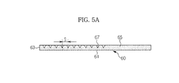
- FIG. 5A is a sectional view taken along the line 1-1 of FIG. 3
- FIG. 5B is a sectional view taken along the line I-I of FIG. 3 , illustrating another embodiment of the present invention.
- the protective panel 60 may have a rectangular shape and may have a predetermined thickness and a length corresponding to a width W of the receiving space 3 (see FIG. 1 ).
- the protective panel 60 may also have a predetermined front-and-rear length F, which is determined to prevent steam discharged upon opening/closing of the door 40 from directly contacting the ceiling 5 of the external structure 1.
- the protective panel 60 may be made of a transparent material, such as glass, acryl-based resin or the like.
- the protective panel 60 may be attached to the ceiling 5 at a position adjacent to the open front side of the receiving space 3, such that one surface, i.e. a front surface of the protective panel 60 is exposed to the outside.
- a lower surface of the protective panel 60 facing the upper surface 41 of the door 40 may serve as an incidence surface 61, into which the light emitted from the operation indicator 53 is introduced.
- the front surface of the protective panel 60, exposed through the open front side of the receiving space 3, may serve as an emission surface 63 from which the light introduced through the incidence surface 61 is emitted.
- the protective panel 60 may be a light guide plate made of a light transmitting material, which serves to transmit the light emitted from the operation indicator 53 in a forward direction of the door 40.
- the transparent protective panel 60 may function not only to prevent deformation of the external structure 1 due to steam discharged from the dishwasher 10, but also to transmit the light, emitted from the operation indicator 53 arranged on the upper surface 41 of the door 40, in a forward direction of the door 40.
- the protective panel 60 may have at least one diffuser pattern 67 integrally formed at an upper surface 65 thereof to diffuse the light directed from the operation indicator 53 to the protective panel 60.
- the diffuser pattern 67 may function to reflect or refract the light introduced through the incidence surface 61 of the protective panel 60, to transmit the light to the emission surface 63 of the protective panel 60.
- the diffuser pattern 67 may be provided at the upper surface 65 of the protective panel 60 at a position facing the operation indicator 53 arranged on the upper surface 41 of the door 40.
- the diffuser pattern 67 may take the form of a V-shaped recess indented inward from the upper surface 65 of the protective panel 60, to refract or reflect the light introduced into the protective panel 60 at a predetermined angle.
- the diffuser pattern 67 in the form of a triangular recess reflects or refracts the light that have emitted from the operation indicator 53 and introduced into the protective panel 60 through the incidence surface 61 and thus, causes condensation of the light emitted from the emission surface 63, enhanced forward brightness and visibility may be accomplished.
- a plurality of diffuser patterns 67 may be spaced apart from one another in a front-and-rear direction F of the protective panel 60, and more particularly, may be equidistantly arranged as illustrated in FIG. 5A .
- a plurality of diffuser patterns 67 may be arranged such that a distance S between the neighboring diffuser patterns 67 is reduced away from the operation indicator 53, i.e. toward the emission surface 63.
- Some of the diffuser patterns 67 adjacent to the operation indicator 53 receive a sufficient quantity of light emitted from the operation indicator 53, but the quantity of light introduced into the remaining diffuser patterns 67 is reduced away from the operation indicator 53. Therefore, when reducing the distance S between the neighboring diffuser patterns 67, it may be possible to increase the quantity of light to be emitted from the emission surface 63 and consequently, enhance visibility of the user.
- the shape of the diffuser patterns 67 is not limited to the above description.
- the diffuser patterns 67 may have a curved cross sectional shape.
- the diffuser patterns 67 integrally formed at the upper surface 65 of the protective panel 60 it may be possible to effectively irradiate the light emitted from the operation indicator 53 through the emission surface 63 in a forward direction of the door 40.
- a reflective sheet 69 may be provided at the incidence surface 61 of the protective panel 60 located between the operation indicator 53 and the emission surface 63. Once the light emitted from the operation indicator 53 is introduced into the incidence surface 61 of the protective panel 61, the reflective sheet 69 prevents the light from leaking from the incidence surface 61 rather than being directed toward the emission surface 63.
- the reflective sheet 69 may be formed at the incidence surface 61 by a silk screen method using paste containing materials exhibiting a high degree of reflectivity.
- the present embodiment illustrates the diffuser patterns 67 as being formed at a partial region of the upper surface 65 of the protective panel 60 to correspond to the operation indicator 53, as illustrated in FIG. 6 , at least one diffuser pattern 67 may be elongated in a direction of the protective panel 60 designated by the arrow W.
- the diffuser patterns 67 may be unnecessary to form the diffuser patterns 67 to correspond to the operation indicators 53 in a one to one ratio.
- the dishwasher 10 begins to be operated.
- the operation indicator 53 emits light corresponding to a current operating state of the dishwasher 10.
- the dishwasher 10 since the dishwasher 10 is embedded in the receiving space 3 of the external structure 1, the outer appearance of the dishwasher 10 is hidden by the external structure 1 once the door 40 is closed, but the light emitted from the operation indicator 53 is introduced into the incidence surface 61 of the protective panel 60 attached to the ceiling 5 of the receiving space 3. Thereby, as the light is directed to the emission surface 63 so as to be emitted to the outside, the user may perceive an operating state of the dishwasher 10.
- the diffuser patterns 67 diffuse the light passing through the protective panel 60, the user visibility may be further enhanced.
- the high-temperature steam contacts the protective panel 60 attached to the ceiling 5 of the receiving space 3. Accordingly, it may be possible to prevent the high-temperature steam from directly contacting the external structure 1, thereby preventing deformation of the external structure 1.
- the protective panel 60 of the present embodiment may serve not only to prevent the high-temperature steam within the dishwasher 10 from directly contacting the external structure 1, but also to allow the user to perceive a current operating state of the built-in dishwasher 10 from the outside.
- the diffuser patterns 67 may be integrally formed at the protective panel 60 and this may enhance productivity of the protective panel 60.
- a built-in dishwasher may allow a user to easily perceive a current operating state of the dishwasher from the outside.
- the built-in dishwasher according to the embodiment may prevent deformation of an external structure in which the dishwasher is embedded, thus providing enhanced reliability in operation.
Abstract
Description
- Embodiments relate to a built-in dishwasher to enable easy observation of an operating state thereof.
- Generally, a dishwasher is an appliance to enable sanitary and efficient washing of dishes and has dish washing and drying functions.
- A dishwasher is mainly installed in a built-in manner along with kitchen components, such as a sink, etc. To improve the aesthetics of a built-in dishwasher, a front surface of the built-in dishwasher is covered with a panel having the same texture and color as those of kitchen components.
- The built-in dishwasher, however, makes observation of an operating state (e.g., washing/rinsing/completion) of the dishwasher difficult and therefore, has been developed to have a configuration for easy observation of the operating state.
- Therefore, it is an aspect to provide a built-in dishwasher, which enables easy observation of an operating state thereof.
- Additional aspects will be set forth in part in the description which follows and, in part, will be apparent from the description, or may be learned by practice of the invention.
- In accordance with one aspect, a built-in dishwasher configured to be inserted into a receiving space of an external structure through an opening of the receiving space, includes a case, a wash tub placed in the case, a door to open or close the wash tub, an operation indicator to indicate an operating state of the dishwasher, and a protective panel provided at a ceiling of the receiving space facing the operation indicator and serving to prevent steam, discharged from the wash tub upon opening of the door, from contacting the external structure, wherein the protective panel is made of a light transmitting material to transmit light, emitted from the operation indicator, in a forward direction of the door.
- The protective panel may be made of any one of glass and transparent resin.
- The protective panel may have a length corresponding to a width of the receiving space and may be located adjacent to the opening of the receiving space to face an upper surface of the door.
- At least one diffuser pattern may be integrally formed at a portion of the protective panel facing the operation indicator and may serve to diffuse the light emitted from the operation indicator.
- The diffuser pattern may take the form of a V-shaped recess indented inward from an upper surface of the protective panel.
- The at least one diffuser pattern may include a plurality of diffuser patterns spaced apart from one another in a front-and-rear direction of the protective panel.
- The plurality of diffuser patterns may be equidistantly arranged.
- A distance between the plurality of diffuser patterns may be reduced away from the operation indicator.
- In accordance with another aspect, a built-in dishwasher configured to be inserted into a receiving space of an external structure through an opening of the receiving space, includes an operation indicator provided at an upper surface of a door that opens or closes a wash tub, and a protective panel having a length corresponding to a width of the receiving space and mounted at a ceiling of the receiving space adjacent to the opening of the receiving space, the protective panel serving to prevent deformation of the external structure due to steam discharged upon opening of the door, wherein the protective panel is made of a light transmitting resin and includes an incidence surface facing the operation indicator and an emission surface facing a forward direction of the door, and at least one diffuser pattern is integrally formed at a portion of an upper surface of the protective panel facing the operation indicator and serves to reflect light introduced through the incidence surface to enable emission of the light through the emission surface.
- An ornamental panel having the same texture and color as the external structure may be provided at a front surface of the door.
- The at least one diffuser pattern may take the form of a V-shaped recess indented inward from the upper surface of the protective panel, and may include a plurality of diffuser patterns spaced apart from one another in a front-and-rear direction of the protective panel.
- The diffuser patterns may be elongated in a width direction of the protective panel.
- A distance between the plurality of diffuser patterns may be reduced toward the emission surface.
- A reflective sheet may be provided at a portion of the incidence surface and may serve to prevent the light from leaking through the incidence surface, rather than being directed to the emission surface.
- In accordance with a further aspect, a built-in dishwasher configured to be inserted into a receiving space of an external structure through an opening of the receiving space, includes an operation indicator to emit light according to an operating state of the dishwasher, and a light guide plate having a length corresponding to a width of the receiving space and mounted at a ceiling of the receiving surface, the light guide plate including an incidence surface facing the operation indicator and an emission surface toward the opening of the receiving space, wherein at least one diffuser pattern is indented in the light guide plate at a position facing the operation indicator and serves to diffuse light introduced into the light guide plate through the incidence surface.
- These and/or other aspects will become apparent and more readily appreciated from the following description of the embodiments, taken in conjunction with the accompanying drawings of which:
-
FIG.1 is a perspective view illustrating a schematic configuration of a dishwasher according to an embodiment; -
FIG. 2 is a sectional view illustrating the interior of the dishwasher according to the embodiment; -
FIG. 3 is a perspective view illustrating a protective panel according to the embodiment; -
FIG. 4 is a sectional view illustrating a part of the dishwasher received in a receiving space according to the embodiment; -
FIG. 5A is a sectional view taken along the line 1-1 ofFIG. 3 ; -
FIG. 5B is a sectional view taken along the line 1-1 ofFIG. 3 , illustrating another embodiment; and -
FIG. 6 is a view illustrating another embodiment of a diffuser pattern formed at the protective panel. - Reference will now be made in detail to a built-in dishwasher according to embodiments, examples of which are illustrated in the accompanying drawings, wherein like reference numerals refer to like elements throughout.
-
FIG. 1 is a perspective view illustrating a schematic configuration of a dishwasher according to an embodiment. - As illustrated in
FIG. 1 , thedishwasher 10 of the present embodiment may be a built-in dishwasher configured to be inserted into anexternal structure 1. Here, theexternal structure 1 may be, e.g., a sink or wall. - To receive the
dishwasher 10, theexternal structure 1 may have areceiving space 3, a front side of which is open. - The
dishwasher 10 may basically include acase 20 defining an outer appearance of thedishwasher 10, adoor 40 pivotally rotatably coupled to a front side of thecase 20, and acontrol panel 50 mounted on anupper surface 41 of thedoor 40. - When the built-in
dishwasher 10 is installed in theexternal structure 1, theentire dishwasher 10 is received in thereceiving space 3 of theexternal structure 1 to prevent exposure of the outer appearance thereof. - In addition, to achieve harmony between the
door 40 and theexternal structure 1, anornamental panel 43 having the same texture and color as those of theexternal structure 1 may be attached to a front surface of thedoor 40. Theornamental panel 43 may be provided with agrip 45 for user grip upon opening/closing of thedoor 40 and thus, may be opened or closed along with thedoor 40. -
FIG. 2 is a sectional view illustrating the interior of the dishwasher according to the embodiment. - As illustrated in
FIG. 2 , thedishwasher 10 may further include awash tub 21 placed in thecase 20 to provide a washing space, and asump 22 provided beneath thewash tub 21 to store wash water therein. - The
wash tub 21 may contain at least onedish basket 26 in which dishes are received. Thedish basket 26 may be supported on arail 27 in a sliding movable manner. - The
wash tub 21 may further contain at least oneinjection nozzle 28 to inject wash water toward the dishes received in thedish basket 26. - In addition, a
water feeder 29 may be provided at a sidewall of thewash tub 21, to supply wash water into thewash tub 21, and aheater 30 may be provided at the bottom of thewash tub 21 to heat wash water. - The
sump 22 may be located at the bottom center of thewash tub 21 to collect wash water and pump the collected wash water. To this end, thesump 22 may include awashing pump 23 to pump wash water at a high pressure and apump motor 24 to drive thewashing pump 23. - The
washing pump 23 may pump wash water up to theinjection nozzle 28 through afirst feed pipe 31 and asecond feed pipe 32. - The
sump 22 may further include aturbidity sensor 25 to detect the pollution level of wash water. A controller (not shown) of thedishwasher 10 may control the implementation number of a washing or rinsing operation based on the pollution level of wash water detected by theturbidity sensor 25. For example, the controller may increase the number of a washing or rinsing operation if the pollution level is high, and may decrease the number of a washing or rinsing operation if the pollution level is low. - A
drain pump 33 and adrain pipe 34 may be coupled to thesump 22 to discharge polluted wash water out of thedishwasher 10. - The
door 40 coupled to thecase 20 may be pivotally rotatable about ahinge shaft 42 provided at a lower end of thecase 20, to open or close a front side of thewash tub 21. - The
control panel 50 mounted on theupper surface 41 of thedoor 40 may be used to display and control operation of thedishwasher 10. Although not shown, a circulation duct may be inserted in an interior space of thedoor 40. - The
control panel 50, as illustrated inFIG. 1 , may include, e.g., adisplay part 51 including a touch panel, etc., to input an operation mode and washing course of thedishwasher 10, anoperation indicator 53 to indicate a current operating state of thedishwasher 10, and a Printed Circuit Board (PCB) connected to these components. - The
display part 51 and theoperation indicator 53 are arranged on theupper surface 41 of thedoor 40. Thedisplay part 51 is provided with operating buttons, such as a button to select a washing, rinsing or drying course, a power on/off button, etc., to allow a user to operate thedishwasher 10. - The
operation indicator 53 includes light emitting elements, such as Light Emitting Diodes (LEDs), etc. During operation of thedishwasher 10, theoperation indicator 53 emits light to allow the user to observe a current operating state of thedishwasher 10. - The above-described
dishwasher 10, as illustrated inFIG. 1 , is received in the receivingspace 3 of theexternal structure 1 so as not to be exposed to the outside. Thus, it may be difficult to observe the light emitted from theoperation indicator 53 arranged on theupper surface 41 of thedoor 40 from the outside. - Further, if the
door 40 is opened or closed after operation of thedishwasher 10, high-temperature steam within thewash tub 21 may be discharged directly to theexternal structure 1. This may cause deformation of theexternal structure 1. - In particular, if the
external structure 1 is made of wood, deformation of theexternal structure 1 may be accelerated. - To prevent deformation of the
external structure 1, in the present embodiment, aprotective panel 60 may be provided at a ceiling of the receivingspace 3 in which thedishwasher 10 is received, to prevent steam discharged upon opening/closing of thedoor 40 from directly contacting theexternal structure 1. -
FIG. 3 is a perspective view illustrating the protective panel according to the embodiment, andFIG. 4 is a sectional view illustrating a part of the dishwasher received in the receiving space. - Also,
FIG. 5A is a sectional view taken along the line 1-1 ofFIG. 3 , andFIG. 5B is a sectional view taken along the line I-I ofFIG. 3 , illustrating another embodiment of the present invention. - Referring to
FIGS. 3 and4 , theprotective panel 60 may have a rectangular shape and may have a predetermined thickness and a length corresponding to a width W of the receiving space 3 (seeFIG. 1 ). - The
protective panel 60 may also have a predetermined front-and-rear length F, which is determined to prevent steam discharged upon opening/closing of thedoor 40 from directly contacting theceiling 5 of theexternal structure 1. - The
protective panel 60 may be made of a transparent material, such as glass, acryl-based resin or the like. Theprotective panel 60 may be attached to theceiling 5 at a position adjacent to the open front side of the receivingspace 3, such that one surface, i.e. a front surface of theprotective panel 60 is exposed to the outside. - In this case, a lower surface of the
protective panel 60 facing theupper surface 41 of thedoor 40 may serve as anincidence surface 61, into which the light emitted from theoperation indicator 53 is introduced. The front surface of theprotective panel 60, exposed through the open front side of the receivingspace 3, may serve as anemission surface 63 from which the light introduced through theincidence surface 61 is emitted. - Specifically, the
protective panel 60 may be a light guide plate made of a light transmitting material, which serves to transmit the light emitted from theoperation indicator 53 in a forward direction of thedoor 40. - In this way, the transparent
protective panel 60 may function not only to prevent deformation of theexternal structure 1 due to steam discharged from thedishwasher 10, but also to transmit the light, emitted from theoperation indicator 53 arranged on theupper surface 41 of thedoor 40, in a forward direction of thedoor 40. - In addition, the
protective panel 60 may have at least onediffuser pattern 67 integrally formed at anupper surface 65 thereof to diffuse the light directed from theoperation indicator 53 to theprotective panel 60. - The
diffuser pattern 67 may function to reflect or refract the light introduced through theincidence surface 61 of theprotective panel 60, to transmit the light to theemission surface 63 of theprotective panel 60. - The
diffuser pattern 67 may be provided at theupper surface 65 of theprotective panel 60 at a position facing theoperation indicator 53 arranged on theupper surface 41 of thedoor 40. Thediffuser pattern 67 may take the form of a V-shaped recess indented inward from theupper surface 65 of theprotective panel 60, to refract or reflect the light introduced into theprotective panel 60 at a predetermined angle. - As the
diffuser pattern 67 in the form of a triangular recess reflects or refracts the light that have emitted from theoperation indicator 53 and introduced into theprotective panel 60 through theincidence surface 61 and thus, causes condensation of the light emitted from theemission surface 63, enhanced forward brightness and visibility may be accomplished. - In one embodiment, a plurality of
diffuser patterns 67 may be spaced apart from one another in a front-and-rear direction F of theprotective panel 60, and more particularly, may be equidistantly arranged as illustrated inFIG. 5A . - In another embodiment, as illustrated in
FIG. 5B , a plurality ofdiffuser patterns 67 may be arranged such that a distance S between the neighboringdiffuser patterns 67 is reduced away from theoperation indicator 53, i.e. toward theemission surface 63. - Some of the
diffuser patterns 67 adjacent to theoperation indicator 53 receive a sufficient quantity of light emitted from theoperation indicator 53, but the quantity of light introduced into the remainingdiffuser patterns 67 is reduced away from theoperation indicator 53. Therefore, when reducing the distance S between the neighboringdiffuser patterns 67, it may be possible to increase the quantity of light to be emitted from theemission surface 63 and consequently, enhance visibility of the user. - Although not illustrated in the present embodiment, the shape of the
diffuser patterns 67 is not limited to the above description. When it is desired to diffuse the light directed from theoperation indicator 53 over a wide range, thediffuser patterns 67 may have a curved cross sectional shape. - For example, owing to various combinations of, e.g., the shape, size or distance of the
diffuser patterns 67 integrally formed at theupper surface 65 of theprotective panel 60, it may be possible to effectively irradiate the light emitted from theoperation indicator 53 through theemission surface 63 in a forward direction of thedoor 40. - In addition, a reflective sheet 69 (see
FIG. 4 ) may be provided at theincidence surface 61 of theprotective panel 60 located between theoperation indicator 53 and theemission surface 63. Once the light emitted from theoperation indicator 53 is introduced into theincidence surface 61 of theprotective panel 61, thereflective sheet 69 prevents the light from leaking from theincidence surface 61 rather than being directed toward theemission surface 63. - The
reflective sheet 69 may be formed at theincidence surface 61 by a silk screen method using paste containing materials exhibiting a high degree of reflectivity. - Meanwhile, although the present embodiment illustrates the
diffuser patterns 67 as being formed at a partial region of theupper surface 65 of theprotective panel 60 to correspond to theoperation indicator 53, as illustrated inFIG. 6 , at least onediffuser pattern 67 may be elongated in a direction of theprotective panel 60 designated by the arrow W. - Even if a plurality of
operation indicators 53 is provided on theupper surface 41 of thedoor 40, it may be unnecessary to form thediffuser patterns 67 at every position corresponding to therespective operation indicators 53 when theelongated diffuser pattern 67 extending in the direction W is formed at theupper surface 65 of theprotective panel 60 and thus, enhanced productivity and universality of theprotective panel 60 may be accomplished. - For example, even if a plurality of
operation indicators 53 is provided on theupper surface 41 of thedoor 40 to emit different colors of light according to a washing, rinsing or drying course of thedishwasher 10, it may be unnecessary to form thediffuser patterns 67 to correspond to theoperation indicators 53 in a one to one ratio. - Hereinafter, operation and effects of the dishwasher according to the embodiment will be described.
- First, if the user inputs a washing condition and washing time to the
control panel 50 in an open state of thedoor 40 and then, closes thedoor 40, thedishwasher 10 begins to be operated. During operation of thedishwasher 10, theoperation indicator 53 emits light corresponding to a current operating state of thedishwasher 10. - In this case, since the
dishwasher 10 is embedded in the receivingspace 3 of theexternal structure 1, the outer appearance of thedishwasher 10 is hidden by theexternal structure 1 once thedoor 40 is closed, but the light emitted from theoperation indicator 53 is introduced into theincidence surface 61 of theprotective panel 60 attached to theceiling 5 of the receivingspace 3. Thereby, as the light is directed to theemission surface 63 so as to be emitted to the outside, the user may perceive an operating state of thedishwasher 10. - Moreover, as the
diffuser patterns 67 diffuse the light passing through theprotective panel 60, the user visibility may be further enhanced. - Meanwhile, even if high-temperature steam within the
dishwasher 10 is discharged upon opening of thedoor 40 after the operation of thedishwasher 10 is completed, the high-temperature steam contacts theprotective panel 60 attached to theceiling 5 of the receivingspace 3. Accordingly, it may be possible to prevent the high-temperature steam from directly contacting theexternal structure 1, thereby preventing deformation of theexternal structure 1. - That is, the
protective panel 60 of the present embodiment may serve not only to prevent the high-temperature steam within thedishwasher 10 from directly contacting theexternal structure 1, but also to allow the user to perceive a current operating state of the built-indishwasher 10 from the outside. - The
diffuser patterns 67 may be integrally formed at theprotective panel 60 and this may enhance productivity of theprotective panel 60. - As is apparent from the above description, a built-in dishwasher according to an embodiment may allow a user to easily perceive a current operating state of the dishwasher from the outside.
- Further, the built-in dishwasher according to the embodiment may prevent deformation of an external structure in which the dishwasher is embedded, thus providing enhanced reliability in operation.
- Although a few embodiments have been shown and described, it would be appreciated by those skilled in the art that changes may be made in these embodiments without departing from the principles and spirit of the invention, the scope of which is defined in the claims and their equivalents.
Claims (15)
- A built-in dishwasher configured to be inserted into a receiving space of an external structure through an opening of the receiving space, comprising:a case;a wash tub placed in the case;a door to open or close the wash tub;an operation indicator to indicate an operating state of the dishwasher; anda protective panel provided at a ceiling of the receiving space facing the operation indicator and serving to prevent steam, discharged from the wash tub upon opening of the door, from contacting the external structure,wherein the protective panel is made of a light transmitting material to transmit light, emitted from the operation indicator, in a forward direction of the door.
- The built-in dishwasher according to claim 1, wherein the protective panel is made of any one of glass and transparent resin.
- The built-in dishwasher according to claim 1, wherein the protective panel has a length corresponding to a width of the receiving space and is located adjacent to the opening of the receiving space to face an upper surface of the door.
- The built-in dishwasher according to claim 3, wherein at least one diffuser pattern is integrally formed at a portion of the protective panel facing the operation indicator and serves to diffuse the light emitted from the operation indicator.
- The built-in dishwasher according to claim 4, wherein the diffuser pattern takes the form of a V-shaped recess indented inward from an upper surface of the protective panel.
- The built-in dishwasher according to claim 4, wherein the at least one diffuser pattern includes a plurality of diffuser patterns spaced apart from one another in a front-and-rear direction of the protective panel.
- The built-in dishwasher according to claim 6, wherein the plurality of diffuser patterns is equidistantly arranged.
- The built-in dishwasher according to claim 6, wherein a distance between the plurality of diffuser patterns is reduced away from the operation indicator.
- A built-in dishwasher configured to be inserted into a receiving space of an external structure through an opening of the receiving space, comprising:an operation indicator provided at an upper surface of a door that opens or closes a wash tub; anda protective panel having a length corresponding to a width of the receiving space and mounted at a ceiling of the receiving space adjacent to the opening of the receiving space, the protective panel serving to prevent deformation of the external structure due to steam discharged upon opening of the door,wherein the protective panel is made of a light transmitting resin and includes an incidence surface facing the operation indicator and an emission surface facing a forward direction of the door, and
wherein at least one diffuser pattern is integrally formed at a portion of an upper surface of the protective panel facing the operation indicator and serves to reflect light introduced through the incidence surface to enable emission of the light through the emission surface. - The built-in dishwasher according to claim 9, wherein an ornamental panel having the same texture and color as the external structure is provided at a front surface of the door.
- The built-in dishwasher according to claim 9, wherein the at least one diffuser pattern takes the form of a V-shaped recess indented inward from the upper surface of the protective panel, and includes a plurality of diffuser patterns spaced apart from one another in a front-and-rear direction of the protective panel.
- The built-in dishwasher according to claim 11, wherein the diffuser patterns are elongated in a width direction of the protective panel.
- The built-in dishwasher according to claim 11, wherein a distance between the plurality of diffuser patterns is reduced toward the emission surface.
- The built-in dishwasher according to claim 11, wherein a reflective sheet is provided at a portion of the incidence surface and serves to prevent the light from leaking through the incidence surface, rather than being directed to the emission surface.
- A built-in dishwasher configured to be inserted into a receiving space of an external structure through an opening of the receiving space, comprising:an operation indicator to emit light according to an operating state of the dishwasher; anda light guide plate having a length corresponding to a width of the receiving space and mounted at a ceiling of the receiving surface, the light guide plate including an incidence surface facing the operation indicator and an emission surface toward the opening of the receiving space,wherein at least one diffuser pattern is indented in the light guide plate at a position facing the operation indicator and serves to diffuse light introduced into the light guide plate through the incidence surface.
Applications Claiming Priority (1)
| Application Number | Priority Date | Filing Date | Title |
|---|---|---|---|
| KR1020100019332A KR20110100383A (en) | 2010-03-04 | 2010-03-04 | Built-in type dish washer |
Publications (2)
| Publication Number | Publication Date |
|---|---|
| EP2394556A2 true EP2394556A2 (en) | 2011-12-14 |
| EP2394556A3 EP2394556A3 (en) | 2012-06-27 |
Family
ID=44121365
Family Applications (1)
| Application Number | Title | Priority Date | Filing Date |
|---|---|---|---|
| EP11152446A Withdrawn EP2394556A3 (en) | 2010-03-04 | 2011-01-28 | Built-in dishwasher |
Country Status (4)
| Country | Link |
|---|---|
| US (1) | US20110215688A1 (en) |
| EP (1) | EP2394556A3 (en) |
| KR (1) | KR20110100383A (en) |
| CN (1) | CN102188217A (en) |
Families Citing this family (8)
| Publication number | Priority date | Publication date | Assignee | Title |
|---|---|---|---|---|
| KR101114320B1 (en) * | 2008-11-05 | 2012-02-14 | 엘지전자 주식회사 | Home appliance and washing machine |
| KR102416688B1 (en) * | 2016-01-06 | 2022-07-05 | 엘지전자 주식회사 | Dish washer |
| CN105686780B (en) * | 2016-03-31 | 2019-01-29 | 宁波市天马厨具有限公司 | Water tank type dish-washing machine door-plate |
| US10883726B2 (en) | 2017-06-28 | 2021-01-05 | Lg Electronics Inc. | Light emitting device in door for cooking appliance and cooking appliance including the same |
| USD841370S1 (en) * | 2017-08-11 | 2019-02-26 | Target Brands, Inc. | Display unit |
| WO2020209480A1 (en) * | 2019-04-08 | 2020-10-15 | 엘지전자 주식회사 | Dishwasher |
| US10753597B1 (en) * | 2019-07-29 | 2020-08-25 | Haier Us Appliance Solutions, Inc. | Light blocking features for indicator lights in an appliance |
| KR20230130819A (en) * | 2022-03-04 | 2023-09-12 | 엘지전자 주식회사 | Dish washer |
Family Cites Families (5)
| Publication number | Priority date | Publication date | Assignee | Title |
|---|---|---|---|---|
| DE10022206C2 (en) * | 2000-05-06 | 2002-06-13 | Miele & Cie | Dishwasher, in particular built-in dishwasher with an optical operating display |
| KR100472468B1 (en) * | 2002-08-07 | 2005-03-10 | 삼성전자주식회사 | Optical guide and image forming apparatus employing it |
| DE10259762A1 (en) * | 2002-12-19 | 2004-07-01 | BSH Bosch und Siemens Hausgeräte GmbH | Household appliance, in particular built-in household appliance |
| DE602005003793T2 (en) * | 2005-04-22 | 2008-12-24 | Electrolux Home Products Corp. N.V. | Built-in dishwasher |
| DE102005040990A1 (en) * | 2005-08-29 | 2007-03-01 | Miele & Cie. Kg | Mountable dishwasher for use in kitchen, has light conductor with several sections provided in the form of teeth for guiding light radiations from light source to front side of dishwasher |
-
2010
- 2010-03-04 KR KR1020100019332A patent/KR20110100383A/en not_active Application Discontinuation
-
2011
- 2011-01-24 US US12/929,431 patent/US20110215688A1/en not_active Abandoned
- 2011-01-28 EP EP11152446A patent/EP2394556A3/en not_active Withdrawn
- 2011-02-25 CN CN2011100481633A patent/CN102188217A/en active Pending
Non-Patent Citations (1)
| Title |
|---|
| None |
Also Published As
| Publication number | Publication date |
|---|---|
| EP2394556A3 (en) | 2012-06-27 |
| KR20110100383A (en) | 2011-09-14 |
| CN102188217A (en) | 2011-09-21 |
| US20110215688A1 (en) | 2011-09-08 |
Similar Documents
| Publication | Publication Date | Title |
|---|---|---|
| EP2394556A2 (en) | Built-in dishwasher | |
| US20070180869A1 (en) | Program-controlled domestic appliance | |
| JP4786992B2 (en) | Built-in equipment for kitchen furniture and kitchen furniture having the same | |
| US9080272B2 (en) | Washing machine | |
| CN101325902A (en) | Domestic appliance, in particular fitted domestic appliance with a controllable operating display | |
| CN102215731B (en) | Console assembly for a dishwashing appliance, and associated apparatus | |
| US10731918B1 (en) | Single-layer appliance indicator light with side-fire LED | |
| KR20080022673A (en) | Control panel assembly for washing machine | |
| EP2094147A1 (en) | Indicating device for indicating status in a domestic machine | |
| US10076227B2 (en) | Dishwasher | |
| US10080476B2 (en) | Cleaning apparatus with illuminated door handle | |
| TW201200667A (en) | Laundry machine and drying machine for laundry purposes | |
| CN104905748A (en) | Dishwasher | |
| JP5985233B2 (en) | Kitchen equipment and kitchen cabinet in which the kitchen equipment is incorporated | |
| KR20230011155A (en) | Refrigerator and home appliance | |
| TWI297600B (en) | Food cleaning mchine | |
| US10975510B1 (en) | Consumer appliance and user interface having one or more touch sensors | |
| US11266291B1 (en) | Dishwasher appliance with a sidefire LED lightguide | |
| CN107532366B (en) | Laundry care appliance with illuminating element | |
| US11918165B2 (en) | Appliance control panel with light diffusion features | |
| US11278179B2 (en) | Status indicator and lighting assembly for an appliance door | |
| CN218074910U (en) | Panel assembly of dish washing machine and dish washing machine | |
| US20230018403A1 (en) | Panel assembly for a home appliance and home appliance therewith | |
| JP2010238584A (en) | Electromagnetic cooker | |
| KR20230116592A (en) | Home appliance |
Legal Events
| Date | Code | Title | Description |
|---|---|---|---|
| AK | Designated contracting states |
Kind code of ref document: A2 Designated state(s): AL AT BE BG CH CY CZ DE DK EE ES FI FR GB GR HR HU IE IS IT LI LT LU LV MC MK MT NL NO PL PT RO RS SE SI SK SM TR |
|
| AX | Request for extension of the european patent |
Extension state: BA ME |
|
| PUAI | Public reference made under article 153(3) epc to a published international application that has entered the european phase |
Free format text: ORIGINAL CODE: 0009012 |
|
| PUAL | Search report despatched |
Free format text: ORIGINAL CODE: 0009013 |
|
| AK | Designated contracting states |
Kind code of ref document: A3 Designated state(s): AL AT BE BG CH CY CZ DE DK EE ES FI FR GB GR HR HU IE IS IT LI LT LU LV MC MK MT NL NO PL PT RO RS SE SI SK SM TR |
|
| AX | Request for extension of the european patent |
Extension state: BA ME |
|
| RIC1 | Information provided on ipc code assigned before grant |
Ipc: A47L 15/42 20060101AFI20120524BHEP |
|
| RAP1 | Party data changed (applicant data changed or rights of an application transferred) |
Owner name: SAMSUNG ELECTRONICS CO., LTD. |
|
| 17P | Request for examination filed |
Effective date: 20121221 |
|
| 17Q | First examination report despatched |
Effective date: 20180618 |
|
| GRAP | Despatch of communication of intention to grant a patent |
Free format text: ORIGINAL CODE: EPIDOSNIGR1 |
|
| INTG | Intention to grant announced |
Effective date: 20181004 |
|
| STAA | Information on the status of an ep patent application or granted ep patent |
Free format text: STATUS: THE APPLICATION IS DEEMED TO BE WITHDRAWN |
|
| 18D | Application deemed to be withdrawn |
Effective date: 20190215 |