EP2455633A1 - Ausrückeinrichtung für eine gezogene Kraftfahrzeugkupplung - Google Patents
Ausrückeinrichtung für eine gezogene Kraftfahrzeugkupplung Download PDFInfo
- Publication number
- EP2455633A1 EP2455633A1 EP10192182A EP10192182A EP2455633A1 EP 2455633 A1 EP2455633 A1 EP 2455633A1 EP 10192182 A EP10192182 A EP 10192182A EP 10192182 A EP10192182 A EP 10192182A EP 2455633 A1 EP2455633 A1 EP 2455633A1
- Authority
- EP
- European Patent Office
- Prior art keywords
- ring
- contour
- load ring
- bearing
- release device
- Prior art date
- Legal status (The legal status is an assumption and is not a legal conclusion. Google has not performed a legal analysis and makes no representation as to the accuracy of the status listed.)
- Granted
Links
- 238000003780 insertion Methods 0.000 claims description 12
- 230000037431 insertion Effects 0.000 claims description 12
- 230000007423 decrease Effects 0.000 claims description 6
- 238000010276 construction Methods 0.000 description 3
- 238000000034 method Methods 0.000 description 2
- 230000002093 peripheral effect Effects 0.000 description 2
- 210000002105 tongue Anatomy 0.000 description 2
- 239000002131 composite material Substances 0.000 description 1
- 238000007598 dipping method Methods 0.000 description 1
- 239000000314 lubricant Substances 0.000 description 1
- 239000007787 solid Substances 0.000 description 1
- 230000007704 transition Effects 0.000 description 1
Images
Classifications
-
- F—MECHANICAL ENGINEERING; LIGHTING; HEATING; WEAPONS; BLASTING
- F16—ENGINEERING ELEMENTS AND UNITS; GENERAL MEASURES FOR PRODUCING AND MAINTAINING EFFECTIVE FUNCTIONING OF MACHINES OR INSTALLATIONS; THERMAL INSULATION IN GENERAL
- F16D—COUPLINGS FOR TRANSMITTING ROTATION; CLUTCHES; BRAKES
- F16D23/00—Details of mechanically-actuated clutches not specific for one distinct type
- F16D23/12—Mechanical clutch-actuating mechanisms arranged outside the clutch as such
- F16D23/14—Clutch-actuating sleeves or bearings; Actuating members directly connected to clutch-actuating sleeves or bearings
- F16D23/143—Arrangements or details for the connection between the release bearing and the diaphragm
- F16D23/144—With a disengaging thrust-ring distinct from the release bearing, and secured to the diaphragm
- F16D23/146—Arrangements for the connection between the thrust-ring and the release bearing
Definitions
- the invention relates to a release device for a towed vehicle clutch, in particular for a diaphragm spring actuated friction clutch, according to the preamble of claim 1.
- a generic release device are, for example, in the DE 195 48 859 C1 and the DE 43 21 115 C2 disclosed.
- Such release devices are mainly used in commercial vehicles.
- the invention has the object to improve a generic release device so that while maintaining an axially short length, a simplified sliding the load ring is made possible on the support element.
- the inventor has recognized that the force required to push the load ring onto the insertion contour of the axial extension or release ring is not determined solely by the radially deformed state assumed by the latter, which may be a radially expanded or compressed state, depending on the present design, of the load ring but that it is also influenced by the rise of the contour line.
- the introduction contour can thus be designed convex with respect to the Aufgleitcardi of the load ring, which by a continuous curve or by a segment-like, bspvv. from several straight sections of different gradients composite curve can be realized.
- the insertion contour on the axial side of the deformation section facing away from the groove has a centering section which enables easy threading and, in the course of the assembly process, centering of the load ring to the outrigger bearing.
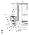
- Fig. 1 shows a executed in solid construction disengaging device 10 for actuating a KraftGermanreibungskuppiung not shown in the drawing with a known manner as a diaphragm spring Ausgurorgan whose spring tongues 27 act together in the radially inner region with the disengaging device 10.
- the disengagement device initially comprises a bearing support 12, which can be displaced axially on a guide tube and is designed here as a two-part sliding sleeve 12 comprising an inner part 12a and an outer part 12b.
- the sliding sleeve 12 carries on a radial flange 14 arranged thereon as an angular contact bearing 16 designed Ausgurlager 16.
- the ball bearing 16 has a respect to the sliding sleeve 12 fixed first, radially outer bearing ring 18 and a circumferential second, radially inner bearing ring 20, which together a central axis A of Defining disengagement bearing.
- the inner bearing ring 20 is extended by means of an axial extension 22 beyond the bearing 16 and is by means of a snapped in an annular groove 19 load ring 24 and a release ring designed as a release ring 26 with the drawing here only partially illustrated tongue ends of a diaphragm spring 27 in operative connection, soft the release member represent the friction clutch to be actuated.
- a corrugated spring 23 which is inserted in a formed on the bearing inner ring 20 groove 25 and axially supported on a retaining ring 21 on the bearing inner ring 20.
- the bearing rings 18, 20 have mutually facing raceways 34, 36 for a plurality of guided in a ball cage 38 and spaced therefrom balls 40. To the Protection against the ingress of dirt and also before the escape of a lubricant located in the bearing are frontally between the bearing rings 18, 20 two contact seals 42, 44 executed.
- the radial flange 14 carries a verrolltes on this holding plate 46, which surrounds the radially outer stationary bearing ring 18 and the seals 42, 44 and thus holds the roller bearing 16 axially to the sliding sleeve 12.
- axial extension 22 provided on the inner bearing ring 20 for mounting the elastically radially deformable load ring 24 has an insertion contour 48, to which the annular groove 19 adjoins.
- the annular groove 19 forms with the release bearing 16 facing flank 19b a first stop contour and a contact surface 26a on the release ring 26 forms a second stop contour for the pressure on disengagement of a clutch load ring 24.
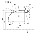
- Fig. 2 shows an enlarged view of the front, free part of the axial extension 22 with the Einstockedkontur 48 and the annular groove 19.
- the load ring 24 is here designed as a circumferentially open wire ring with a round cross-section and in three different, when pushing this successively occupied positions I. -III drawn.
- the load ring 24 In a first position I, the load ring 24 is already threaded onto the insertion contour 48, more precisely on a centering section 48a, and centered thereon.
- This centering portion 48a is characterized in that its outer diameter is smaller or at most equal to the inner diameter of the load ring 24 in the relaxed state.
- the load ring 24 is located at the end of the centering section 48a and at the same time at the transition to a deforming section 48b designed as a widening section, in which the load ring 19 is elastically deformed radially, in particular widened in this arrangement.
- the deformation or widening section 48b thus extends at the insertion contour 48 from an axial initial position P, at which a system diameter DP assigned there corresponds approximately to an effective diameter of the load ring 24 in the relaxed state, but in the example in particular slightly larger than the inner diameter of the load ring 24 in the no-load state, up to an end position Q located axially between the initial position P and the annular groove 19, at which a plant diameter DQ assigned there and thus the radial deformation, here in particular the widening of the load ring 24, is an extreme value, here in the form of a maximum value reached.
- the load ring 19 is temporarily forced into a free space 11 bounded by the second stop contour 26a.
- the deformation portion 48b is characterized by a contour line 49 extending from the initial position P to the end position Q, the rise of which decreases between these two positions P, Q in the axial sliding direction PQ of the load ring 24. That is, the course of the contour line 49 gradually decreases, as in FIG Fig. 2 is clearly visible.
- the groove bottom 19a has an outer diameter which is approximately equal and in the present example, in particular slightly larger to the effective diameter of the load ring 24 in the relaxed state, in this case to its inner diameter. In the embodiment discussed here, the load ring 24 thus sits slightly biased in the groove 19th
- FIG DE 43 21 115 C2 a construction according to the invention is shown in FIG DE 43 21 115 C2 underlying, in its basic structure with the illustrated embodiment of the Fig. 1 matches and their entire disclosure content belongs to the teaching of the present invention except for the specific design of the insertion.
- the insertion contour and the axially adjoining annular groove with the first abutment contour are formed on a radial inner circumferential surface of a disengagement ring.
- a free space with the second stop contour is provided on the outer peripheral surface of an axial extension which dips into the outlet collar, the load ring also bearing here between the stop contours.
- the deformation portion of the disengagement ring has a contour line, the increase in the axial Aufgleitides of the load ring decreases.
- the insertion contour and the axially adjacent annular groove with the first abutment contour can also be formed on a radial inner circumferential surface of an axial extension of one of the bearing rings.
- a free space with the second stop contour is provided on the outer peripheral surface of a dipping into the axial extension Ausgurringes, the load ring also here between the two stop contours compressive rests when acting on the releaser forces in the release direction.
- the deformation section of the axial extension has a contour line, the increase in the axial Aufgleit Vietnamese of the load ring decreases.
Landscapes
- Engineering & Computer Science (AREA)
- General Engineering & Computer Science (AREA)
- Mechanical Engineering (AREA)
- Mechanical Operated Clutches (AREA)
Abstract
Description
- Die Erfindung betrifft eine Ausrückvorrichtung für eine gezogene Kraftfahrzeugkupplung, insbesondere für eine membranfederbetätigbare Reibungskupplung, gemäß dem Oberbegriff des Patentanspruchs 1. Zwei verschiedene Ausführungsformen einer solchen gattungsgemäßen Ausrückvorrichtung sind beispielsweise in der
DE 195 48 859 C1 und derDE 43 21 115 C2 offenbart. Solche Ausrückvorrichtungen werden hauptsächlich bei Nutzkraftfahrzeugen eingesetzt. - Zum Zusammenbau einer Kupplung mit deren Ausrückvorrichtung an einem Fahrzeugantriebstrang wird gemäß dem in der vorgenannten
DE 195 48 859 C1 erläuterten Ausführungsbeispiel ein an einer Membranfeder der Kupplung angeordneter Ausrückring mit einem daran lose befestigten Lastring durch die Wirkung einer Ausrückgabel axial auf die Einführkontur des Ausrücklagers aufgeschoben bzvv. aufgedrückt. Dabei wird der Lastring von dem freien Ende der Einführkontur aufgenommen und im weiteren Verlauf allmählich zentriert, um dann in einem Verformungsbereich, insbesondere einem Aufweitbereich der Einführkontur radial bis zum Erreichen eines maximalen Außendurchmessers der Einführkontur aufgeweitet zu werden und schließlich in eine sich daran anschließende Ringnut einzuschnappen. - Die für dieses Zusammenfügen manuell aufzubringende Kraft ist relativ hoch, wodurch der Vorgang für das Montagepersonal kraftraubend, ermüdend und auch fehleranfällig ist. Das erläuterte Montageprinzip findet ebenfalls bei der, in der
DE 43 21 115 C2 beschriebenen Ausrückvorrichtung in einer geometrisch modifizierten Variante Anwendung. - Von diesem Stand der Technik ausgehend, liegt der Erfindung die Aufgabe zugrunde, eine gattungsgemäße Ausrückvorrichtung so zu verbessern, dass unter Beibehaltung einer axial kurzen Baulänge ein erleichtertes Aufschieben des Lastringes auf dessen Trägerelement ermöglicht wird.
- Das vorstehende Problem wird bei einer Ausrückvorrichtung der eingangs erläuterten Art gelöst, indem an dem Verformungsabschnitt eine Konturlinie vorgesehen ist, deren Anstieg in Aufgieitrichtung des Lastringes abnimmt.
- Der Erfinder hat erkannt, dass der Kraftaufwand zum Aufschieben des Lastringes auf die Einführkontur des Axiaifortsatzes oder des Ausrückringes nicht allein durch den von diesem jeweils eingenommenen radialen Verformungszustand, der je nach vorliegender Konstruktion ein radial aufgeweiteter oder ein zusammengedrückter Zustand sein kann, des Lastringes bestimmt wird, sondern dass dieser auch von dem Anstieg der Konturlinie beeinflusst wird.
- Von dieser Erkenntnis ausgehend wird vorgeschlagen, die von dem Lastring beim Aufgleiten durchfahrene Bahnkurve, d.h. die Konturlinie des Verformungsabschnitts so zu gestalten, dass diese in einer Anfangsposition, in der der Lastring nur vergleichsweise gering verformt, einen Anstieg aufweist, welcher gegenüber einem Anstieg in einer in der axialen Montagerichtung weiter verschobenen Position, größer ist. Durch diese Maßnahme werden die zum Aufschieben des Lastringes erforderlichen Axial-oder Montagekräfte in einem hinteren Teil der Konturlinie, wo bereits eine erhebliche Radialverformung erreicht ist, reduziert. Auf diese Weise wird zwar die, vergleichsweise geringe Montagekraft in einem vorderen Wegteil des Verformungsbereichs mit geringer Verformung des Lastringes etwas erhöht, jedoch wird in einem hinteren Wegteil des Verformungsbereichs die maximal erforderliche Montagekraft erniedrigt. Somit wird insgesamt die Montage einer gattungsgemäßen Ausrückvorrichtung spürbar vereinfacht. Die Einführkontur kann somit bezüglich der Aufgleitrichtung des Lastringes konvex gestaltet sein, was durch eine kontinuierliche Kurve oder durch eine segmentartige, bspvv. aus mehreren Geradenabschnitten unterschiedlicher Steigungen zusammengesetzte Kurve realisiert werden kann.
- Gemäß einer vorteilhaften Variante weist die Einführkontur auf der, der Nut abgewandten Axialseite des Verformungsabschnittes einen Zentrierabschnitt auf, welcher ein leichtes Einfädeln und im Verlauf des Montagevorgangs eine Zentrierung des Lastringes zum Ausrücl<lager ermöglicht.
- Nachfolgend wird die Erfindung anhand der beigefügten Figur beispielhaft erläutert. Es zeigen:
- Fig. 1
- eine in gezogener Bauweise ausgeführte Ausrückvorrichtung,
- Fig. 2
- einen Ausschnitt der Ausrückvorrichtung von
Fig. 1 mit einer vergrößerten Darstellung einer Einführkontur und einer Ringnut für einen Lastring. -
Fig. 1 zeigt eine in gezogener Bauweise ausgeführte Ausrückvorrichtung 10 zum Betätigen einer zeichnerisch nicht dargestellten Kraftfahrzeugreibungskuppiung mit einer in an sich bekannter Weise als Membranfeder ausgeführten Ausrückorgan, deren Federzungen 27 im radial inneren Bereich mit der Ausrückvorrichtung 10 zusammen wirken. - Die Ausrückvorrichtung umfasst zunächst einen auf einem Führungsrohr axial verlagerbaren Lagerträger 12, weicher hier als zweiteilige, ein Innenteil 12a und ein Außenteil 12b umfassende Schiebehülse 12 ausgebildet ist. Die Schiebehülse 12 trägt an einem daran angeordneten Radialflansch 14 ein als Schrägkugellager ausgeführtes Ausrücklager 16. Das Kugellager 16 weist einen bezüglich der Schiebehülse 12 feststehenden ersten, radial äußeren Lagerring 18 und einen umlaufenden zweiten, radial inneren Lagerring 20 auf, welche gemeinsam eine Mittelachse A des Ausrücklagers definieren.
- Der innere Lagerring 20 ist mittels eines Axialfortsatzes 22 über das Lager 16 hinaus verlängert und steht mittels einem in einer Ringnut 19 eingeschnappten Lastring 24 und einem als Ausrückring ausgeführten Ausrückring 26 mit den hier zeichnerisch nur teilweise dargestellten Zungenenden einer Membranfeder 27 in Wirkverbindung, weiche das Ausrückorgan der zu betätigenden Reibungskupplung darstellen. Zur Gewährleistung einer spielfreien Anlage des Ausrückringes 26 an dem Lastring 24 dient eine Wellfeder 23, welche in einer am Lagerinnenring 20 ausgeformten Nut 25 eingesetzt ist und sich an einem Sicherungsring 21 axial am Lagerinnenring 20 abstützt. Die Lagerringe 18, 20 weisen zueinander zugewandte Laufbahnen 34, 36 für mehrere in einem Kugelkäfig 38 geführte und von diesem beabstandete Kugeln 40 auf. Zum Schutz vor dem Eindringen von Schmutz und gleichfalls vor dem Austreten von einem im Lagerinneren befindlichen Schmiermittel sind stirnseitig zwischen den Lagerringen 18, 20 zwei Berührungsdichtungen 42, 44 ausgeführt. Der Radialflansch 14 trägt ein an diesem verrolltes Halteblech 46, welches den radial äußeren, feststehenden Lagerring 18 und die Dichtungen 42, 44 umgreift und somit das Wälzlager 16 axial an der Schiebehülse 12 festhält.
- In
Fig. 1 ist erkennbar, dass der an dem inneren Lagerring 20 vorgesehene Axialfortsatz 22 zur Montage des elastisch radial verformbaren Lastringes 24 eine Einführkontur 48 aufweist, an die sich die Ringnut 19 anschließt. Die Ringnut 19 bildet mit der zum Ausrücklager 16 weisenden Flanke 19b eine erste Anschlagkontur und eine Anlagefläche 26a am Ausrückring 26 bildet eine zweite Anschlagkontur für den beim Ausrücken einer Kupplung druckbelasteten Lastring 24 aus. -
Fig. 2 zeigt eine vergrößerte Darstellung des vorderen, freien Teils des Axialfortsatzes 22 mit der Einführkontur 48 und der Ringnut 19. Der Lastring 24 ist hier als ein in Kreisumfangsrichtung offener Drahtring mit einem runden Querschnitt ausgeführt und in drei verschiedenen, beim Aufschieben von diesem nacheinander eingenommenen Stellungen I-III eingezeichnet. In einer ersten Stellung I ist der Lastring 24 bereits auf die Einführkontur 48, genauer auf einem Zentrierabschnitt 48a eingefädelt und von diesem zentriert. Dieser Zentrierabschnitt 48a ist dadurch gekennzeichnet, dass dessen Außendurchmesser kleiner oder maximal gleich dem Innendurchmesser des Lastrings 24 im entspannten Zustand ist. - In der eingezeichneten Stellung I befindet sich der Lastring 24 am Ende des Zentrierabschnitts 48a und gleichzeitig am Übergang zu einem als Aufweitabschnitt ausgebildeten Verformungsabschnitt 48b, in welchem der Lastring 19 elastisch radial verformt, bei dieser Anordnung insbesondere aufgeweitet wird. Der Verformungs- bzw. Aufweitabschnitt 48b erstreckt sich an der Einführkontur 48 demnach von einer axialen Anfangsposition P, an welcher ein dort zugeordneter Anlagedurchmesser DP etwa einem Wirkungsdurchmesser des Lastringes 24 im entspannten Zustand entspricht, insbesondere im Beispiel jedoch geringfügig größer als der Innendurchmesser des Lastringes 24 im lastlosen Zustand ist, bis hin zu einer axial zwischen der Anfangsposition P und der Ringnut 19 befindlichen Endposition Q, an dem ein dort zugeordneter Anlagedurchmesser DQ und damit die radiale Verformung, hier insbesondere die Aufweitung des Lastrings 24 einen Extremwert, vorliegend in Form eines Maximalwertes erreicht. Während des Aufgleitens wird der Lastring 19 in einen von der zweiten Anschlagkontur 26a begrenzten Freiraum 11 zeitweilig hineingedrängt. Der Verformungsabschnitt 48b ist durch eine von der Anfangsposition P zu der Endposition Q verlaufende Konturlinie 49 charakterisiert, deren Anstieg zwischen diesen beiden Positionen P, Q in der axialen Aufgleitrichtung PQ des Lastringes 24 abnimmt. Das heißt, dass der Verlauf der Konturlinie 49 allmählich abfällt, wie in
Fig. 2 deutlich erkennbar ist. In der Stellung III befindet sich der Lastring 24 in der Nut 19 eingeschnappt, deren Nutgrund 19a einen Außendurchmesser aufweist, der etwa gleich und im vorliegenden Beispiel insbesondere geringfügig größer zu dem Wirkungsdurchmesser des Lastrings 24 im entspannten Zustand, vorliegend zu dessen Innendurchmesser, ist. In dem hier behandelten Ausführungsbeispiel sitzt der Lastring 24 somit geringfügig vorgespannt in der Nut 19. - Bei einer weiteren, hier zeichnerisch nicht dargestellten Variante einer erfindungsgemäßen Ausrückeinrichtung liegt eine Konstruktion gemäß der
DE 43 21 115 C2 zugrunde, die in deren grundsätzlichen Aufbau mit dem hier erläuterten Ausführungsbeispiel derFig. 1 übereinstimmt und deren gesamter Offenbarungsgehalt bis auf die konkrete Ausgestaltung der Einführkontur zur Lehre der vorliegenden Erfindung gehört. Insbesondere sind bei dieser Variante einer Ausrückeinrichtung die Einführkontur und die sich daran axial anschließende Ringnut mit der ersten Anschlagkontur an einer radialen Innenumfangsfläche eines Ausrückringes ausgebildet. Hierbei ist an der Außenumfangsfläche eines in den Ausrücl<ring eintauchenden Axialfortsatzes ein Freiraum mit der zweiten Anschlagkontur vorgesehen, wobei der Lastring auch hier zwischen den Anschlagkonturen anliegt. Gemäß der vorliegenden Erfindung weist der Verformungsabschnitt des Ausrückringes eine Konturlinie auf, deren Anstieg in der axialen Aufgleitrichtung des Lastringes abnimmt. - Bei einer noch weiteren, hier ebenfalls zeichnerisch nicht dargestellten Variante einer erfindungsgemäßen Ausrückeinrichtung können die Einführkontur und die sich daran axial anschließende Ringnut mit der ersten Anschlagkontur auch an einer radialen Innenumfangsfläche eines Axialfortsatzes von einem der Lagerringe ausgebildet sein. Hierbei ist an der Außenumfangsfläche eines in den Axialfortsatz eintauchenden Ausrückringes ein Freiraum mit der zweiten Anschlagkontur vorgesehen, wobei der Lastring auch hier zwischen den beiden Anschlagkonturen druckbelastbar anliegt, wenn am Ausrücker Kräfte in Ausrückrichtung wirken. Gemäß der vorliegenden Erfindung weist dabei der Verformungsabschnitt des Axialfortsatzes eine Konturlinie auf, deren Anstieg in der axialen Aufgleitrichtung des Lastringes abnimmt.
Claims (2)
- Ausrückeinrichtung (10) für eine gezogene Kraftfahrzeugkupplung, umfassend- ein Ausrücklager (16) mit einem radial äußeren und einem radial inneren Lagerring (18; 20), welche gemeinsam eine Mittelachse (A) des Ausrücklagers (16) definieren, wobei- einer der Lagerringe (18; 20) zum Umlauf mit der Kraftfahrzeugkupplung vorgesehen ist und einen Axialfortsatz (22) aufweist, weiter umfassend- einen Ausrückring (26), welcher in Wirkverbindung zu dem Axialfortsatz (22) und zu einem Ausrückorgan (27) der Kraftfahrzeugkupplung steht oder bringbar ist, wobei- an dem Axialfortsatz (22) oder an dem Ausrückring (26) eine Einführkontur (48) und eine axial folgende Ringnut (19) mit einer ersten Anschlagkontur (19b) ausgebildet sind und wobei- an dem jeweils anderen Teil von Axialfortsatz (22) und Ausrückring (26) ein von einer zweiten Anschlagkontur (26a) begrenzter Freiraum (11) vorgesehen ist, und wobei- die Ausrückeinrichtung (10) einen radial elastisch verformbaren Lastring (24) umfasst, der in Anlagekontakt zu den Anschlagkonturen steht oder bringbar ist, und wobei- die Einführkontur (48) einen Verformungsabschnitt (48b) für den Lastring (24) aufweist, welcher sich an der Einführkontur (48) von einer axialen Anfangsposition (P), an welcher ein zugeordneter Anlagedurchmesser (DP) etwa einem Wirkungsdurchmesser des Lastringes (24) im entspannten Zustand entspricht bis zu einer axial zwischen der Anfangsposition (P) und der Ringnut (19) befindlichen Endposition (Q) erstreckt, an dem ein zugeordneter Anlagedurchmesser (DQ) einen Extremwert erreicht,dadurch gekennzeichnet,
dass der Verformungsabschnitt (48b) eine Konturlinie (49) aufweist, deren Anstieg in Aufgleitrichtung (PQ) des Lastringes (24) abnimmt. - Ausrückeinrichtung nach Patentanspruch 1,
dadurch gekennzeichnet, dass die Einführkontur (48) auf der, der Ringnut (19) abgewandten Axialseite des Verformungsabschnittes (48b) einen Zentrierabschnitt (48a) aufweist.
Priority Applications (2)
| Application Number | Priority Date | Filing Date | Title |
|---|---|---|---|
| EP10192182.3A EP2455633B1 (de) | 2010-11-23 | 2010-11-23 | Ausrückeinrichtung für eine gezogene Kraftfahrzeugkupplung |
| DE202010016772U DE202010016772U1 (de) | 2010-11-23 | 2010-11-23 | Ausrückeinrichtung für eine gezogene Kraftfahrzeugkupplung |
Applications Claiming Priority (1)
| Application Number | Priority Date | Filing Date | Title |
|---|---|---|---|
| EP10192182.3A EP2455633B1 (de) | 2010-11-23 | 2010-11-23 | Ausrückeinrichtung für eine gezogene Kraftfahrzeugkupplung |
Publications (2)
| Publication Number | Publication Date |
|---|---|
| EP2455633A1 true EP2455633A1 (de) | 2012-05-23 |
| EP2455633B1 EP2455633B1 (de) | 2016-01-13 |
Family
ID=43736194
Family Applications (1)
| Application Number | Title | Priority Date | Filing Date |
|---|---|---|---|
| EP10192182.3A Active EP2455633B1 (de) | 2010-11-23 | 2010-11-23 | Ausrückeinrichtung für eine gezogene Kraftfahrzeugkupplung |
Country Status (2)
| Country | Link |
|---|---|
| EP (1) | EP2455633B1 (de) |
| DE (1) | DE202010016772U1 (de) |
Citations (6)
| Publication number | Priority date | Publication date | Assignee | Title |
|---|---|---|---|---|
| FR2545172A1 (fr) * | 1983-04-26 | 1984-11-02 | Valeo | Montage de butee de debrayage, piece d'accostage pour un tel montage et procedes de mise en place et de demontage du montage de butee |
| EP0224393A1 (de) * | 1985-10-09 | 1987-06-03 | Valeo | Trennbarer Zusammenbau eines ein Entriegelungselement tragenden Kupplungsausrücklagers, insbesondere für Kraftfahrzeuge |
| WO1994028327A1 (en) * | 1993-05-27 | 1994-12-08 | Automotive Products (Italia) S.R.L. | A clutch release bearing assembly |
| EP0709591A2 (de) * | 1992-04-06 | 1996-05-01 | FICHTEL & SACHS AG | Ausrückeranordnung für eine Kraftfahrzeug-Reibungskupplung |
| DE19548859C1 (de) | 1995-12-27 | 1997-02-20 | Fichtel & Sachs Ag | Verliersichere Vorlastfeder |
| DE4321115C2 (de) | 1992-07-21 | 2001-11-29 | Mannesmann Sachs Ag | Schnappverbindungsanordnung für einen Kupplungsausrücker |
-
2010
- 2010-11-23 EP EP10192182.3A patent/EP2455633B1/de active Active
- 2010-11-23 DE DE202010016772U patent/DE202010016772U1/de not_active Expired - Lifetime
Patent Citations (6)
| Publication number | Priority date | Publication date | Assignee | Title |
|---|---|---|---|---|
| FR2545172A1 (fr) * | 1983-04-26 | 1984-11-02 | Valeo | Montage de butee de debrayage, piece d'accostage pour un tel montage et procedes de mise en place et de demontage du montage de butee |
| EP0224393A1 (de) * | 1985-10-09 | 1987-06-03 | Valeo | Trennbarer Zusammenbau eines ein Entriegelungselement tragenden Kupplungsausrücklagers, insbesondere für Kraftfahrzeuge |
| EP0709591A2 (de) * | 1992-04-06 | 1996-05-01 | FICHTEL & SACHS AG | Ausrückeranordnung für eine Kraftfahrzeug-Reibungskupplung |
| DE4321115C2 (de) | 1992-07-21 | 2001-11-29 | Mannesmann Sachs Ag | Schnappverbindungsanordnung für einen Kupplungsausrücker |
| WO1994028327A1 (en) * | 1993-05-27 | 1994-12-08 | Automotive Products (Italia) S.R.L. | A clutch release bearing assembly |
| DE19548859C1 (de) | 1995-12-27 | 1997-02-20 | Fichtel & Sachs Ag | Verliersichere Vorlastfeder |
Also Published As
| Publication number | Publication date |
|---|---|
| DE202010016772U1 (de) | 2011-03-24 |
| EP2455633B1 (de) | 2016-01-13 |
Similar Documents
| Publication | Publication Date | Title |
|---|---|---|
| DE2611558A1 (de) | Kupplungsdrucklager | |
| DE3413670C2 (de) | Montageanordnung für einen Kupplungsausrücker, insbesondere für Kraftfahrzeuge | |
| DE102008047170A1 (de) | Kupplungsbetätigungssystem | |
| DE3446866A1 (de) | Montageanordnung fuer einen kupplungsausruecker, fuer eine solche montage geeigneter kupplungsausruecker, und verfahren zu dessen axialer trennung | |
| DE3034057A1 (de) | Ausruecklager | |
| WO2013143832A1 (de) | Nehmerzylinder | |
| DE102014013077A1 (de) | Elastomerlager als Buchsenlager | |
| DE102007013694A1 (de) | Selbstzentrierendes Kupplungsausrücklager | |
| DE69705672T2 (de) | Kupplungsausrücklager mit einem elastischen Ring | |
| DE69618149T2 (de) | Schutzflansch für Rollenlager, damit ausgerüstetes Lager und Herstellungsverfahren für einen Lagerring, der mit einem Schutzflansch versehen ist | |
| DE19631725B4 (de) | Mechanische Sicherung für Bauteile | |
| DE202009003663U1 (de) | Selbstzentrierende Kupplungsausrücklagervorrichtung | |
| DE102008004027A1 (de) | Nehmerzylinder | |
| WO2008086763A1 (de) | Nehmerzylinder | |
| EP2455633B1 (de) | Ausrückeinrichtung für eine gezogene Kraftfahrzeugkupplung | |
| DE102012222878A1 (de) | Arbeitszylinder mit Transportsicherung | |
| DE102013208218A1 (de) | Kugelgewindetrieb | |
| DE2242140A1 (de) | Ausruecklager fuer reibungskupplungen mit gegen axialblattfeder radial in einem gehaeuse verschiebbarem lager | |
| WO2013107688A1 (de) | Wälzlageranordnung, insbesondere ausrücklageranordnung | |
| DE2630716A1 (de) | Kugellager-ausruecker, insbesondere fuer kraftfahrzeugkupplungen | |
| WO2022199744A1 (de) | Kolben für eine ausrückvorrichtung mit fixierung | |
| DE102017119986A1 (de) | Wälzlageranordnung für eine Lenksäule | |
| DE20121298U1 (de) | Befestigungsanordnung | |
| DE69002213T2 (de) | Zugkraftbetätigtes Kupplungslager. | |
| DE69716006T2 (de) | Befestigung eines kupplungsrücklagers |
Legal Events
| Date | Code | Title | Description |
|---|---|---|---|
| PUAI | Public reference made under article 153(3) epc to a published international application that has entered the european phase |
Free format text: ORIGINAL CODE: 0009012 |
|
| AK | Designated contracting states |
Kind code of ref document: A1 Designated state(s): AL AT BE BG CH CY CZ DE DK EE ES FI FR GB GR HR HU IE IS IT LI LT LU LV MC MK MT NL NO PL PT RO RS SE SI SK SM TR |
|
| AX | Request for extension of the european patent |
Extension state: BA ME |
|
| 17P | Request for examination filed |
Effective date: 20120604 |
|
| 17Q | First examination report despatched |
Effective date: 20130415 |
|
| GRAP | Despatch of communication of intention to grant a patent |
Free format text: ORIGINAL CODE: EPIDOSNIGR1 |
|
| INTG | Intention to grant announced |
Effective date: 20150811 |
|
| GRAS | Grant fee paid |
Free format text: ORIGINAL CODE: EPIDOSNIGR3 |
|
| GRAA | (expected) grant |
Free format text: ORIGINAL CODE: 0009210 |
|
| AK | Designated contracting states |
Kind code of ref document: B1 Designated state(s): AL AT BE BG CH CY CZ DE DK EE ES FI FR GB GR HR HU IE IS IT LI LT LU LV MC MK MT NL NO PL PT RO RS SE SI SK SM TR |
|
| REG | Reference to a national code |
Ref country code: GB Ref legal event code: FG4D Free format text: NOT ENGLISH |
|
| REG | Reference to a national code |
Ref country code: CH Ref legal event code: EP |
|
| REG | Reference to a national code |
Ref country code: IE Ref legal event code: FG4D Free format text: LANGUAGE OF EP DOCUMENT: GERMAN |
|
| REG | Reference to a national code |
Ref country code: AT Ref legal event code: REF Ref document number: 770744 Country of ref document: AT Kind code of ref document: T Effective date: 20160215 |
|
| REG | Reference to a national code |
Ref country code: DE Ref legal event code: R096 Ref document number: 502010010929 Country of ref document: DE |
|
| REG | Reference to a national code |
Ref country code: LT Ref legal event code: MG4D |
|
| REG | Reference to a national code |
Ref country code: NL Ref legal event code: MP Effective date: 20160113 |
|
| PG25 | Lapsed in a contracting state [announced via postgrant information from national office to epo] |
Ref country code: NL Free format text: LAPSE BECAUSE OF FAILURE TO SUBMIT A TRANSLATION OF THE DESCRIPTION OR TO PAY THE FEE WITHIN THE PRESCRIBED TIME-LIMIT Effective date: 20160113 |
|
| PG25 | Lapsed in a contracting state [announced via postgrant information from national office to epo] |
Ref country code: GR Free format text: LAPSE BECAUSE OF FAILURE TO SUBMIT A TRANSLATION OF THE DESCRIPTION OR TO PAY THE FEE WITHIN THE PRESCRIBED TIME-LIMIT Effective date: 20160414 Ref country code: HR Free format text: LAPSE BECAUSE OF FAILURE TO SUBMIT A TRANSLATION OF THE DESCRIPTION OR TO PAY THE FEE WITHIN THE PRESCRIBED TIME-LIMIT Effective date: 20160113 Ref country code: IT Free format text: LAPSE BECAUSE OF FAILURE TO SUBMIT A TRANSLATION OF THE DESCRIPTION OR TO PAY THE FEE WITHIN THE PRESCRIBED TIME-LIMIT Effective date: 20160113 Ref country code: FI Free format text: LAPSE BECAUSE OF FAILURE TO SUBMIT A TRANSLATION OF THE DESCRIPTION OR TO PAY THE FEE WITHIN THE PRESCRIBED TIME-LIMIT Effective date: 20160113 Ref country code: ES Free format text: LAPSE BECAUSE OF FAILURE TO SUBMIT A TRANSLATION OF THE DESCRIPTION OR TO PAY THE FEE WITHIN THE PRESCRIBED TIME-LIMIT Effective date: 20160113 Ref country code: NO Free format text: LAPSE BECAUSE OF FAILURE TO SUBMIT A TRANSLATION OF THE DESCRIPTION OR TO PAY THE FEE WITHIN THE PRESCRIBED TIME-LIMIT Effective date: 20160413 |
|
| PG25 | Lapsed in a contracting state [announced via postgrant information from national office to epo] |
Ref country code: LV Free format text: LAPSE BECAUSE OF FAILURE TO SUBMIT A TRANSLATION OF THE DESCRIPTION OR TO PAY THE FEE WITHIN THE PRESCRIBED TIME-LIMIT Effective date: 20160113 Ref country code: LT Free format text: LAPSE BECAUSE OF FAILURE TO SUBMIT A TRANSLATION OF THE DESCRIPTION OR TO PAY THE FEE WITHIN THE PRESCRIBED TIME-LIMIT Effective date: 20160113 Ref country code: PL Free format text: LAPSE BECAUSE OF FAILURE TO SUBMIT A TRANSLATION OF THE DESCRIPTION OR TO PAY THE FEE WITHIN THE PRESCRIBED TIME-LIMIT Effective date: 20160113 Ref country code: RS Free format text: LAPSE BECAUSE OF FAILURE TO SUBMIT A TRANSLATION OF THE DESCRIPTION OR TO PAY THE FEE WITHIN THE PRESCRIBED TIME-LIMIT Effective date: 20160113 Ref country code: SE Free format text: LAPSE BECAUSE OF FAILURE TO SUBMIT A TRANSLATION OF THE DESCRIPTION OR TO PAY THE FEE WITHIN THE PRESCRIBED TIME-LIMIT Effective date: 20160113 Ref country code: IS Free format text: LAPSE BECAUSE OF FAILURE TO SUBMIT A TRANSLATION OF THE DESCRIPTION OR TO PAY THE FEE WITHIN THE PRESCRIBED TIME-LIMIT Effective date: 20160513 Ref country code: PT Free format text: LAPSE BECAUSE OF FAILURE TO SUBMIT A TRANSLATION OF THE DESCRIPTION OR TO PAY THE FEE WITHIN THE PRESCRIBED TIME-LIMIT Effective date: 20160513 |
|
| REG | Reference to a national code |
Ref country code: DE Ref legal event code: R097 Ref document number: 502010010929 Country of ref document: DE Ref country code: FR Ref legal event code: PLFP Year of fee payment: 7 |
|
| PG25 | Lapsed in a contracting state [announced via postgrant information from national office to epo] |
Ref country code: DK Free format text: LAPSE BECAUSE OF FAILURE TO SUBMIT A TRANSLATION OF THE DESCRIPTION OR TO PAY THE FEE WITHIN THE PRESCRIBED TIME-LIMIT Effective date: 20160113 Ref country code: EE Free format text: LAPSE BECAUSE OF FAILURE TO SUBMIT A TRANSLATION OF THE DESCRIPTION OR TO PAY THE FEE WITHIN THE PRESCRIBED TIME-LIMIT Effective date: 20160113 |
|
| PLBE | No opposition filed within time limit |
Free format text: ORIGINAL CODE: 0009261 |
|
| STAA | Information on the status of an ep patent application or granted ep patent |
Free format text: STATUS: NO OPPOSITION FILED WITHIN TIME LIMIT |
|
| PG25 | Lapsed in a contracting state [announced via postgrant information from national office to epo] |
Ref country code: SK Free format text: LAPSE BECAUSE OF FAILURE TO SUBMIT A TRANSLATION OF THE DESCRIPTION OR TO PAY THE FEE WITHIN THE PRESCRIBED TIME-LIMIT Effective date: 20160113 Ref country code: SM Free format text: LAPSE BECAUSE OF FAILURE TO SUBMIT A TRANSLATION OF THE DESCRIPTION OR TO PAY THE FEE WITHIN THE PRESCRIBED TIME-LIMIT Effective date: 20160113 Ref country code: CZ Free format text: LAPSE BECAUSE OF FAILURE TO SUBMIT A TRANSLATION OF THE DESCRIPTION OR TO PAY THE FEE WITHIN THE PRESCRIBED TIME-LIMIT Effective date: 20160113 Ref country code: RO Free format text: LAPSE BECAUSE OF FAILURE TO SUBMIT A TRANSLATION OF THE DESCRIPTION OR TO PAY THE FEE WITHIN THE PRESCRIBED TIME-LIMIT Effective date: 20160113 |
|
| 26N | No opposition filed |
Effective date: 20161014 |
|
| PG25 | Lapsed in a contracting state [announced via postgrant information from national office to epo] |
Ref country code: BG Free format text: LAPSE BECAUSE OF FAILURE TO SUBMIT A TRANSLATION OF THE DESCRIPTION OR TO PAY THE FEE WITHIN THE PRESCRIBED TIME-LIMIT Effective date: 20160413 Ref country code: SI Free format text: LAPSE BECAUSE OF FAILURE TO SUBMIT A TRANSLATION OF THE DESCRIPTION OR TO PAY THE FEE WITHIN THE PRESCRIBED TIME-LIMIT Effective date: 20160113 Ref country code: BE Free format text: LAPSE BECAUSE OF NON-PAYMENT OF DUE FEES Effective date: 20161130 |
|
| REG | Reference to a national code |
Ref country code: CH Ref legal event code: PL |
|
| GBPC | Gb: european patent ceased through non-payment of renewal fee |
Effective date: 20161123 |
|
| PG25 | Lapsed in a contracting state [announced via postgrant information from national office to epo] |
Ref country code: CH Free format text: LAPSE BECAUSE OF NON-PAYMENT OF DUE FEES Effective date: 20161130 Ref country code: LI Free format text: LAPSE BECAUSE OF NON-PAYMENT OF DUE FEES Effective date: 20161130 |
|
| REG | Reference to a national code |
Ref country code: IE Ref legal event code: MM4A |
|
| PG25 | Lapsed in a contracting state [announced via postgrant information from national office to epo] |
Ref country code: LU Free format text: LAPSE BECAUSE OF NON-PAYMENT OF DUE FEES Effective date: 20161130 |
|
| REG | Reference to a national code |
Ref country code: FR Ref legal event code: PLFP Year of fee payment: 8 |
|
| PG25 | Lapsed in a contracting state [announced via postgrant information from national office to epo] |
Ref country code: IE Free format text: LAPSE BECAUSE OF NON-PAYMENT OF DUE FEES Effective date: 20161123 Ref country code: GB Free format text: LAPSE BECAUSE OF NON-PAYMENT OF DUE FEES Effective date: 20161123 |
|
| REG | Reference to a national code |
Ref country code: AT Ref legal event code: MM01 Ref document number: 770744 Country of ref document: AT Kind code of ref document: T Effective date: 20161123 |
|
| PG25 | Lapsed in a contracting state [announced via postgrant information from national office to epo] |
Ref country code: AT Free format text: LAPSE BECAUSE OF NON-PAYMENT OF DUE FEES Effective date: 20161123 |
|
| REG | Reference to a national code |
Ref country code: BE Ref legal event code: MM Effective date: 20161130 |
|
| PG25 | Lapsed in a contracting state [announced via postgrant information from national office to epo] |
Ref country code: CY Free format text: LAPSE BECAUSE OF FAILURE TO SUBMIT A TRANSLATION OF THE DESCRIPTION OR TO PAY THE FEE WITHIN THE PRESCRIBED TIME-LIMIT Effective date: 20160113 Ref country code: HU Free format text: LAPSE BECAUSE OF FAILURE TO SUBMIT A TRANSLATION OF THE DESCRIPTION OR TO PAY THE FEE WITHIN THE PRESCRIBED TIME-LIMIT; INVALID AB INITIO Effective date: 20101123 |
|
| PG25 | Lapsed in a contracting state [announced via postgrant information from national office to epo] |
Ref country code: MK Free format text: LAPSE BECAUSE OF FAILURE TO SUBMIT A TRANSLATION OF THE DESCRIPTION OR TO PAY THE FEE WITHIN THE PRESCRIBED TIME-LIMIT Effective date: 20160113 Ref country code: TR Free format text: LAPSE BECAUSE OF FAILURE TO SUBMIT A TRANSLATION OF THE DESCRIPTION OR TO PAY THE FEE WITHIN THE PRESCRIBED TIME-LIMIT Effective date: 20160113 Ref country code: MC Free format text: LAPSE BECAUSE OF FAILURE TO SUBMIT A TRANSLATION OF THE DESCRIPTION OR TO PAY THE FEE WITHIN THE PRESCRIBED TIME-LIMIT Effective date: 20160113 |
|
| PG25 | Lapsed in a contracting state [announced via postgrant information from national office to epo] |
Ref country code: MT Free format text: LAPSE BECAUSE OF FAILURE TO SUBMIT A TRANSLATION OF THE DESCRIPTION OR TO PAY THE FEE WITHIN THE PRESCRIBED TIME-LIMIT Effective date: 20160113 |
|
| REG | Reference to a national code |
Ref country code: FR Ref legal event code: PLFP Year of fee payment: 9 |
|
| PG25 | Lapsed in a contracting state [announced via postgrant information from national office to epo] |
Ref country code: AL Free format text: LAPSE BECAUSE OF FAILURE TO SUBMIT A TRANSLATION OF THE DESCRIPTION OR TO PAY THE FEE WITHIN THE PRESCRIBED TIME-LIMIT Effective date: 20160113 |
|
| PGFP | Annual fee paid to national office [announced via postgrant information from national office to epo] |
Ref country code: FR Payment date: 20191014 Year of fee payment: 10 |
|
| PG25 | Lapsed in a contracting state [announced via postgrant information from national office to epo] |
Ref country code: FR Free format text: LAPSE BECAUSE OF NON-PAYMENT OF DUE FEES Effective date: 20201130 |
|
| P01 | Opt-out of the competence of the unified patent court (upc) registered |
Effective date: 20230528 |
|
| PGFP | Annual fee paid to national office [announced via postgrant information from national office to epo] |
Ref country code: DE Payment date: 20241001 Year of fee payment: 15 |