EP2455569A2 - Vorrichtung für ein bewegbares Möbelteil und Möbel - Google Patents
Vorrichtung für ein bewegbares Möbelteil und Möbel Download PDFInfo
- Publication number
- EP2455569A2 EP2455569A2 EP20110009074 EP11009074A EP2455569A2 EP 2455569 A2 EP2455569 A2 EP 2455569A2 EP 20110009074 EP20110009074 EP 20110009074 EP 11009074 A EP11009074 A EP 11009074A EP 2455569 A2 EP2455569 A2 EP 2455569A2
- Authority
- EP
- European Patent Office
- Prior art keywords
- damping
- damping device
- contact
- furniture part
- movable
- Prior art date
- Legal status (The legal status is an assumption and is not a legal conclusion. Google has not performed a legal analysis and makes no representation as to the accuracy of the status listed.)
- Withdrawn
Links
Images

Classifications
-
- E—FIXED CONSTRUCTIONS
- E05—LOCKS; KEYS; WINDOW OR DOOR FITTINGS; SAFES
- E05F—DEVICES FOR MOVING WINGS INTO OPEN OR CLOSED POSITION; CHECKS FOR WINGS; WING FITTINGS NOT OTHERWISE PROVIDED FOR, CONCERNED WITH THE FUNCTIONING OF THE WING
- E05F5/00—Braking devices, e.g. checks; Stops; Buffers
- E05F5/006—Braking devices, e.g. checks; Stops; Buffers for hinges having a cup-shaped fixing part, e.g. for attachment to cabinets or furniture
-
- E—FIXED CONSTRUCTIONS
- E05—LOCKS; KEYS; WINDOW OR DOOR FITTINGS; SAFES
- E05Y—INDEXING SCHEME ASSOCIATED WITH SUBCLASSES E05D AND E05F, RELATING TO CONSTRUCTION ELEMENTS, ELECTRIC CONTROL, POWER SUPPLY, POWER SIGNAL OR TRANSMISSION, USER INTERFACES, MOUNTING OR COUPLING, DETAILS, ACCESSORIES, AUXILIARY OPERATIONS NOT OTHERWISE PROVIDED FOR, APPLICATION THEREOF
- E05Y2201/00—Constructional elements; Accessories therefor
- E05Y2201/20—Brakes; Disengaging means; Holders; Stops; Valves; Accessories therefor
- E05Y2201/25—Mechanical means for force or torque adjustment therefor
-
- E—FIXED CONSTRUCTIONS
- E05—LOCKS; KEYS; WINDOW OR DOOR FITTINGS; SAFES
- E05Y—INDEXING SCHEME ASSOCIATED WITH SUBCLASSES E05D AND E05F, RELATING TO CONSTRUCTION ELEMENTS, ELECTRIC CONTROL, POWER SUPPLY, POWER SIGNAL OR TRANSMISSION, USER INTERFACES, MOUNTING OR COUPLING, DETAILS, ACCESSORIES, AUXILIARY OPERATIONS NOT OTHERWISE PROVIDED FOR, APPLICATION THEREOF
- E05Y2600/00—Mounting or coupling arrangements for elements provided for in this subclass
- E05Y2600/10—Adjustable
- E05Y2600/12—Adjustable by manual operation
-
- E—FIXED CONSTRUCTIONS
- E05—LOCKS; KEYS; WINDOW OR DOOR FITTINGS; SAFES
- E05Y—INDEXING SCHEME ASSOCIATED WITH SUBCLASSES E05D AND E05F, RELATING TO CONSTRUCTION ELEMENTS, ELECTRIC CONTROL, POWER SUPPLY, POWER SIGNAL OR TRANSMISSION, USER INTERFACES, MOUNTING OR COUPLING, DETAILS, ACCESSORIES, AUXILIARY OPERATIONS NOT OTHERWISE PROVIDED FOR, APPLICATION THEREOF
- E05Y2800/00—Details, accessories and auxiliary operations not otherwise provided for
- E05Y2800/69—Permanence of use
- E05Y2800/692—Temporary use, e.g. removable tools
-
- E—FIXED CONSTRUCTIONS
- E05—LOCKS; KEYS; WINDOW OR DOOR FITTINGS; SAFES
- E05Y—INDEXING SCHEME ASSOCIATED WITH SUBCLASSES E05D AND E05F, RELATING TO CONSTRUCTION ELEMENTS, ELECTRIC CONTROL, POWER SUPPLY, POWER SIGNAL OR TRANSMISSION, USER INTERFACES, MOUNTING OR COUPLING, DETAILS, ACCESSORIES, AUXILIARY OPERATIONS NOT OTHERWISE PROVIDED FOR, APPLICATION THEREOF
- E05Y2800/00—Details, accessories and auxiliary operations not otherwise provided for
- E05Y2800/74—Specific positions
-
- E—FIXED CONSTRUCTIONS
- E05—LOCKS; KEYS; WINDOW OR DOOR FITTINGS; SAFES
- E05Y—INDEXING SCHEME ASSOCIATED WITH SUBCLASSES E05D AND E05F, RELATING TO CONSTRUCTION ELEMENTS, ELECTRIC CONTROL, POWER SUPPLY, POWER SIGNAL OR TRANSMISSION, USER INTERFACES, MOUNTING OR COUPLING, DETAILS, ACCESSORIES, AUXILIARY OPERATIONS NOT OTHERWISE PROVIDED FOR, APPLICATION THEREOF
- E05Y2900/00—Application of doors, windows, wings or fittings thereof
- E05Y2900/20—Application of doors, windows, wings or fittings thereof for furniture, e.g. cabinets
Definitions
- the guide device may comprise, for example, a hinge with a hinge mechanism or a pull-out guide with a sliding mechanism.
- a damping device for damping the relative movement of device or stop parts when pivoting or moving the movable furniture part may be provided.
- the movement of the movable furniture part is damped with the damping device or, for example, attenuated or braked relative to the body relative to the body on a final leg before reaching a closed position of the movable furniture part.
- unwanted impact noise and kickback movements of the furniture part or damage to the furniture can be avoided.
- the damping device which comprises, for example, a fluid damper or gas or liquid damper, in particular components such as a base body with a damper housing thereon including inner part, said damper housing and inner part defined during pivoting or moving the furniture part during operation of the damping device relative to each other are movable overcoming a resistance.
- the inner part may comprise a piston arrangement which is displaceable in a damper housing designed as a cylinder.
- the damper housing or the inner part can serve as a contact part, which comes at least temporarily in contact for damping with a movable during pivoting or moving of the furniture part portion of the device.
- an adjustment arrangement may be present.
- Object of the present invention is to improve furniture or devices of the aforementioned type with respect to the damping device.
- the invention relates to a device for a movable furniture part, in particular for a door, flap or drawer, wherein the device has a first stop member attachable to a body, which via a hinge mechanism with an attachable to the movable furniture part second stop member for pivoting the movable Furniture part is connected, and wherein in the mounted state of the device for damping the relative movement of device parts of the device during pivoting of the movable furniture part, a damping device is present, which comprises a damper housing and an inner part accommodated on the damper housing, which are mutually movable, and the damper housing or Inner part as a contact part is used, which at least temporarily comes into contact for damping with a movable portion of the device during pivoting of the furniture part, and an adjustment arrangement is provided, with which an adjustment of the damping provided with the damping device is vor spiritbar.
- the device may in particular be a hinge or a pull-out or rail guide or a combination thereof.
- a sliding mechanism for moving the movable furniture part may be formed or a combination of a hinge and a sliding mechanism for pivoting and / or moving the movable furniture part.
- a first main aspect of the invention is that the adjustment arrangement is designed to adjust a mounting position of the damping device in the mounted state on the device changeable for setting a desired damping, wherein the damping device is fixed in the predetermined mounting position on the device.
- the attachment to the device may in particular be a predefinable mounting position on the device or the relevant stop member on which the damping device is present. This is z.
- the damping device is preferably present on the second stop part.
- the hinge or the pull-out guide with the damping device has, in particular, a component that can be attached to the hinge or the pull-out guide or, as a rule, is separate, which forms the damping device with its components.
- the adjustment of the damping is advantageous because it is with the change in position of the Damping device realized on the device a simple adjustment.
- the inner working mechanism of the damping device so the characteristic of the relative movement of the inner part and damper housing is not changed.
- Once the production of the damping device predetermined internal operating characteristics of the damper remains unaffected by the changed attachment position. An action on the damper does not take place, which is advantageous in view of the reliability and the life of the damping device. Because the interaction of damper housing and inner part is realized in particular on small-sized constructions.
- Such dampers are, for example, fluid dampers with sensitively configured sealing and / or guiding arrangements.
- the damping device is not changed, for example, with regard to a possible travel or stroke of the inner part relative to the damper housing, but only their mounting position on the device.
- the damping device can thus be designed to be less complicated and / or space-saving or smaller in size than previous damping devices concerned.
- the adjustment arrangement is designed such that a position of a contact element of a contact point of the device, via which the device for damping temporarily with the contact part of the damping device can be brought into abutment to specify the remaining device.
- the adjustment or an influence on the damping effect on the non-damper parts of the device can be made.
- An action on the damping device does not or does not take place. So it is a contour of the contact point of the device is changed, which affects the interaction of contact point and contact part of the damper and thus influences the damping.
- the contact element of the contact point is in particular infinitely adjustable to the remaining portions of the device. The time or duration of the damping and / or the course of the interaction between the contact element and the contact part during the damping process depends on the contour of the contact point.
- the contact element can be adjusted in particular in its distance from the contact part of the damping device, so be moved closer to the contact part or further away from the contact part. If it is moved closer, the damping effect, for example, starts earlier or can act over a longer period of motion furniture movement, or if it is moved further away, the damping effect begins later or remain the contact element and the contact longer contactless. This concerns the damped direction of movement, in particular closing movement, the other direction or opening direction remains unaffected by the damping device. When moving back the furniture part so after the closing movement when opening comes according to the contact element again out of contact with the contact part of the damping device once this has reached its fully extended standby position and is ready for the next steaming when re-closing the furniture part.
- adjusting means which comprise a screw arrangement.
- a screw arrangement for example, manually and without the aid of an adjusting tool, for example, manually the position of the contact element to be changed.
- a screw head of a screw of the screw assembly may be the contact element.
- the adjustment of the position of the contact point is infinitely possible.
- a spindle arrangement it may also be advantageous to provide a spindle arrangement, a worm arrangement, an eccentric arrangement or a detent arrangement.
- An arrangement with an inclined plane, for example in the manner of a bevel gear for adjusting the contact point may be advantageous.
- the damping device is designed in such a way that a relative position of the contact part relative to the damping device in a standby position in which the contact point of the device comes into contact with the contact part remains independent of the fixable attachment position of the damping device on the device ,
- the damping device itself is not adjusted, for example, in its mounting position or a stroke of the contact part, which is covered in a damping process from the contact part.
- the damping device is designed such that an established possible movement path of the contact part is maintained relative to other parts of the damping device regardless of the fixable mounting position of the damper housing on the device. This also leads to a comparatively simple design of the damping device.
- An advantageous modification of the subject invention is characterized in that the damping device is designed such that an established, possible movement path of the contact part is adjustable relative to other parts of the damping device.
- switch means are provided with which the damping device is adjustable.
- the damping device is adjustable such that in a switching position, a damping effect is set up, so can act, or alternatively in any other setable with the switch means setting a damping with the damping device is completely inactivated or prevented.
- a damping effect does not take place in the latter case.
- the damping device advantageously does not need to be removed. Conversely, later, without the installation of the damping device is necessary again, the inactivated existing damping device can be reactivated.
- the switch means are designed for their manual operation. So it is easy and without tools, in particular with a handle possible to operate the switch means and thus either the damping device to actively set or completely off.
- the damping device is positioned in a recessed area of a stop member, in particular a device pot.
- a stop member in particular a device pot.
- the damping device comprises a cylinder component and a piston component with extension, which are movable relative to each other at a damping.
- cylinder-piston assemblies are small in size and have proven themselves as damper arrangements or stand standard or commercially available in different configurations.
- spring means are provided, with which a spring force can be applied to the cylinder component or the piston component, which is effective in the relative movement of the cylinder component and the piston component.
- a spring force or according to a corresponding spring constant of the spring used it is possible, in particular, to absorb load peaks that occur in the short-term on the damping device during a damping operation in order to counteract, for example, damage or noise.
- the invention also relates to a piece of furniture having a body and a movable furniture part hinged to the body, in particular a door, flap or drawer.
- a piece of furniture having a body and a movable furniture part hinged to the body, in particular a door, flap or drawer.
- the furniture part has in particular a hinge with which a pivoting of a door or flap relative to the body is possible.
- FIGS. 1 to 3 show a part of a hinge according to the invention for a to a furniture body pivotally attachable furniture part (not shown), wherein a trained for attachment to the furniture body first stop part of the hinge is not shown.
- a hinge arm 1 of the hinge is connected in the assembled state of the hinge with the first stop member, so that the hinge, the movable furniture part can be moved from a closed relative to the furniture body closing position in an open position and pivoted back. This results in a pivoting of the movable furniture part according to the double arrow P1 about a pivot axis S.
- the pivot axis belongs to a pivot bearing SL of the hinge.
- the hinge arm 1 is pivotally connected via the pivot bearing SL to the fixable on the movable furniture part second stop member comprising a hinge cup 2 and a mounting flange 2a.
- FIGS. 1 to 3 shown positions of the hinge parts to each other corresponds in the mounted state of the hinge on the furniture of a relative to the furniture body partially open position of the movable furniture part, ie between a complete closed body and completely open furniture part position.
- the hinge cup 2 is used for mounting on the movable furniture part in a correctly positioned on the furniture part depression or recording, for example, a blind hole and two more laterally to the blind hole existing holes in which mounting pins 2b, which are present on the underside of the mounting flange 2a, engage, fixed in the correct position by means of the mounting pins 2b from above engaging screws 14.
- a base plate 6 of a damping device 3 adapted to the semicircular shape of an inner wall of the recess of the hinge cup 2, so that the damping device 3 is inserted in the recessed portion of the hinge cup 2.
- a semicircular outer portion of the base plate 6 rests against a semicircular inner wall 2c of the hinge cup 2 viewed from above on the recessed hinge cup 2.
- two inwardly extending projections 2d are formed in the wall of the hinge cup 2, on which the damping device 3 is supported in each case and thus held in a fixed position in the hinge cup 2 slightly clamped.
- the damping device 3 sits on a bottom surface of the recess of the hinge cup 2.
- the damping device 3 can accordingly from above into the hinge cup 2 without problems z. B. be used by hand in the manufacture of the hinge by clamping.
- a bow spring 15 in particular as a closing mechanism to bring spring-loaded the movable furniture part in a closed position to the carcass closed position or to hold there.
- the damping device 3 acts upon closing of the furniture part and brakes the closing movement of the furniture part on its last partial path.
- the contact of the support point 4 takes place with a contact part of the damping device 3, wherein the contact part is formed on a damper housing 5 of the damping device 3.
- the damper housing 5 is relative to the base plate 6 of the damping device 3 according to double arrow P2 in FIG. 4 guided back and forth against a damping resistor displaced, wherein in the FIGS. 4 and 5 one with respect to the base plate 6 maximum moved out position of the damper housing 5 is shown.
- the damper housing 5 forms the front portion of a damper cylinder 7, which is guided on guide webs 16 of the base plate 6.
- damper cylinder 7 relative to the base plate 6 via springs 8, 9 biased in an extended stop position according to FIGS. 4 and 5 held, with the side of the damper cylinder 7 protruding lugs 17 press against mechanical stops 18 on the base plate 6.
- the damper cylinder 7 can be pressed by compressing the springs 8, 9 from its protruding position on the base plate 6 inwards.
- a relative movement of a piston engaging in an inner or hollow volume of the damper cylinder 7 occurs, on which a piston rod 10 is fixed and fixed with its fine end to a piston rod fixing 11 on the base plate 6.
- the damper cylinder 7 and the piston together with the piston rod 10 act like a per se known piston-cylinder damper or fluid damper and will therefore not be further explained.
- FIG. 5 is an attachable to the base plate 6 attachable adjusting pin not shown, which is used in a Stellstattage 12 and 13 and then holds the fully inserted damper cylinder 7 against the force of the springs 8 and 9.
- the damping effect of the damping device 3 can be completely inactive while the adjusting pin is inserted.
Landscapes
- Hinges (AREA)
- Drawers Of Furniture (AREA)
- Fluid-Damping Devices (AREA)
Abstract
Description
- Möbel mit einem an einem Möbelkorpus bewegbar aufgenommenen Möbelteil wie z. B. eine Tür, Klappe oder Schublade, das über einen Gelenkmechanismus oder einen Schiebemechanismus verschwenkt oder verschoben werden kann, sind bekannt. Dabei ist am Korpus ein erstes Anschlagteil und am bewegbaren Möbelteil ein zweites Anschlagteil einer Führungseinrichtung vorgesehen. Die Führungseinrichtung kann beispielsweise ein Scharnier mit Gelenkmechanismus oder eine Auszugführung mit Schiebemechanismus umfassen.
- Im montierten Zustand der Führungseinrichtung kann eine Dämpfvorrichtung für eine Dämpfung der Relativbewegung von Vorrichtungs- bzw. Anschlagteilen beim Verschwenken oder Verschieben des bewegbaren Möbelteils vorgesehen sein. Damit wird als Folge daraus auch die Bewegung des bewegbaren Möbelteils mit der Dämpfvorrichtung gedämpft bzw. zum Beispiel auf einer letzten Teilstrecke vor Erreichen einer Schließposition des bewegbaren Möbelteils relativ zum Korpus gedämpft bzw. abgebremst. So können unerwünschte Anschlaggeräusche und Rückschlagbewegungen des Möbelteils bzw. Beschädigungen an dem Möbel vermieden werden.
- Die Dämpfvorrichtung, welche beispielsweise einen Fluiddämpfer bzw. Gas- oder Flüssigkeitsdämpfer umfasst, weist insbesondere Komponenten wie einen Grundkörper mit einem daran vorhandenen Dämpfergehäuse samt Innenteil auf, wobei Dämpfergehäuse und Innenteil beim Verschwenken oder Verschieben des Möbelteils im Betrieb der Dämpfvorrichtung definiert relativ zueinander unter Überwindung eines Widerstandes bewegbar sind. Beispielsweise kann das Innenteil eine Kolbenanordnung umfassen, die in einem als Zylinder ausgebildeten Dämpfergehäuse hin und her verschieblich ist. Dabei kann entweder das Dämpfergehäuse oder das Innenteil als Kontaktteil dienen, welches für die Dämpfung mit einem beim Verschwenken oder Verschieben des Möbelteils bewegbaren Abschnitt der Vorrichtung zumindest zeitweise in Kontakt gelangt. Mit dem beginnenden Kontakt wird der Dämpfvorgang der Bewegung der betreffenden Teile der Vorrichtung und damit des bewegbaren Möbelteils eingeleitet. Um auf die Dämpfvorrichtung bezüglich einer bereitgestellten Dämpfwirküng einzuwirken, kann ggf. eine Einstellanordnung vorhanden sein.
- Aufgabe der vorliegenden Erfindung ist es, Möbel bzw. Vorrichtungen der einleitend genannten Art im Hinblick auf die Dämpfvorrichtung zu verbessern.
- Diese Aufgabe wird durch die unabhängigen Ansprüche gelöst.
- Die abhängigen Ansprüche betreffen vorteilhafte Varianten der Erfindung.
- Die Erfindung geht aus von einer Vorrichtung für ein bewegbares Möbelteil, insbesondere für eine Tür, Klappe oder Schublade, wobei die Vorrichtung ein an einem Korpus anbringbares erstes Anschlagteil aufweist, welches über einen Gelenkmechanismus mit einem am bewegbaren Möbelteil anbringbaren zweiten Anschlagteil für ein Verschwenken des bewegbaren Möbelteils verbunden ist, und wobei im montierten Zustand der Vorrichtung zur Dämpfung der Relativbewegung von Vorrichtungsteilen der Vorrichtung beim Verschwenken des bewegbaren Möbelteils eine Dämpfvorrichtung vorhanden ist, welche ein Dämpfergehäuse und ein am Dämpfergehäuse aufgenommenes Innenteil umfasst, die zueinander bewegbar sind, und das Dämpfergehäuse oder das Innenteil als Kontaktteil dient, welches für eine Dämpfung mit einem beim Verschwenken des Möbelteils bewegbaren Abschnitt der Vorrichtung zumindest zeitweise in Kontakt gelangt, und eine Einstellanordnung vorgesehen ist, mit welcher eine Einstellung der mit der Dämpfvorrichtung bereitgestellten Dämpfung vornehmbar ist. Die Vorrichtung kann insbesondere ein Scharnier oder eine Auszug- bzw. Schienenführung oder eine Kombination daraus sein.
- Anstelle des Gelenkmechanismus kann auch ein Schiebemechanismus zum Verschieben des bewegbaren Möbelteils ausgebildet sein oder eine Kombination aus einem Gelenk- und einem Schiebemechanismus zum Verschwenken und/oder Verschieben des bewegbaren Möbelteils.
- Ein erster Hauptaspekt der Erfindung liegt darin, dass die Einstellanordnung ausgebildet ist, für eine Einstellung einer gewünschten Dämpfung eine Anbringposition der Dämpfvorrichtung im montierten Zustand an der Vorrichtung veränderbar vorzugeben, wobei die Dämpfvorrichtung in der vorgegebenen Anbringposition an der Vorrichtung festgelegt ist. Das bedeutet, dass vor und nach einer Veränderung der Anbringposition der Dämpfvorrichtung die Anbringposition im Betrieb erhalten bleibt. Die bestehende Relativbeweglichkeit von Dämpfergehäuse und Innenteil bleibt davon unberührt. Die Festlegung an der Vorrichtung kann insbesondere eine vorgebbare Montageposition an der Vorrichtung bzw. dem betreffenden Anschlagteil, an welchem die Dämpfvorrichtung vorhanden ist, sein. Damit wird z. B. der Grundkörper der Dämpfvorrichtung an dem Anschlagteil insbesondere lösbar befestigt beispielsweise angesteckt oder aufgeklipst. Die Dämpfvorrichtung ist bevorzugt am zweiten Anschlagteil vorhanden.
- Das Scharnier bzw. die Auszugführung mit der Dämpfvorrichtung, weist insbesondere ein am Scharnier bzw. der Auszugführung anbringbares bzw. in der Regel separates Bauteil auf, das die Dämpfvorrichtung mit ihren Komponenten bildet. Mit der vorgeschlagenen Anordnung erfolgt die Einstellung der Dämpfung vorteilhaft, denn es wird mit der Positionsänderung der Dämpfvorrichtung an der Vorrichtung eine einfache Verstellung realisiert. Insbesondere wird dabei der innere Wirkmechanismus der Dämpfvorrichtung, also die Charakteristik der Relativbewegung von Innenteil und Dämpfergehäuse nicht verändert. Eine einmal mit der Herstellung der Dämpfvorrichtung vorgegebene innere Wirkcharakteristik des Dämpfers bleibt von der geänderten Anbringposition unbeeinflusst. Ein Einwirken auf den Dämpfer findet nicht statt, was im Hinblick auf die Zuverlässigkeit und die Lebensdauer der Dämpfvorrichtung vorteilhaft ist. Denn das Zusammenwirken von Dämpfergehäuse und Innenteil ist insbesondere über klein bauende Konstruktionen realisiert. Solche Dämpfer sind zum Beispiel Fluiddämpfer mit sensibel gestalteten Dicht- und/oder Führungsanordnungen.
- Die Dämpfvorrichtung wird beispielsweise im Hinblick auf einen möglichen Verfahrweg bzw. Hub des Innenteils relativ zum Dämpfergehäuse nicht verändert, sondern nur deren Anbringposition an der Vorrichtung.
- Vorteilhafterweise kann damit die Dämpfvorrichtung im Vergleich zu bisherigen betreffenden Dämpfvorrichtungen weniger kompliziert und/oder platzsparender bzw. kleiner dimensioniert ausgebildet werden.
- Ein weiterer Hauptaspekt der Erfindung liegt darin, dass die Einstellanordnung derart ausgebildet ist, eine Position eines Kontaktelements einer Kontaktstelle der Vorrichtung, über welche die Vorrichtung für eine Dämpfung zeitweise mit dem Kontaktteil der Dämpfvorrichtung in Anlage bringbar ist, zur verbleibenden Vorrichtung verlagerbar vorzugeben. Somit kann die Einstellung der bzw. eine Einflussnahme auf die Dämpfwirkung an den nicht zur Dämpfvorrichtung gehörenden Teilen der Vorrichtung vorgenommen werden. Ein Einwirken auf die Dämpfvorrichtung erfolgt nicht bzw. muss nicht erfolgen. Es wird also sozusagen eine Kontur der Kontaktstelle der Vorrichtung verändert, was sich auf das Zusammenspiel von Kontaktstelle und Kontaktteil des Dämpfers auswirkt und damit die Dämpfung beeinflusst. Das Kontaktelement der Kontaktstelle ist zu den verbleibenden Abschnitten der Vorrichtung insbesondere stufenlos verstellbar. Von der Kontur der Kontaktstelle hängt der Zeitpunkt bzw. Dauer der Dämpfung und/oder der Verlauf des Zusammenwirkens zwischen dem Kontaktelement und dem Kontaktteil beim Dämpfvorgang ab.
- Das Kontaktelement kann insbesondere in seinem Abstand zum Kontaktteil der Dämpfvorrichtung verstellt werden, also näher hin zum Kontaktteil oder weiter vom Kontaktteil weg verstellt werden. Wird es näher hin verstellt, setzt die Dämpfwirkung zum Beispiel früher ein bzw. kann über einen längere Bewegungsphase der Möbelteilbewegung wirken, oder wenn es weiter weg verstellt wird, setzt die Dämpfwirkung erst später ein bzw. bleiben das Kontaktelement und das Kontaktteil länger kontaktlos. Dies betrifft die gedämpfte Bewegungsrichtung insbesondere Schließbewegung, die andere Richtung bzw. Öffnungsrichtung bleibt von der Dämpfvorrichtung unbeeinflusst. Beim Zurückbewegen des Möbelteils also nach der Schließbewegung beim Öffnen kommt entsprechend das Kontaktelement wieder außer Kontakt mit dem Kontaktteil der Dämpfvorrichtung sobald dieses seine voll ausgefahrene Bereitschaftsposition erreicht hat und für den nächsten Dämpfvorgang beim erneuten Schließen des Möbelteils bereit ist.
- Mit der Verstellung wird bei einer zu dämpfenden Bewegung des bewegbaren Möbelteils der Moment bzw. die Relativstellung der zueinander bewegbaren Teile des Scharniers oder des Auszugs vorgegeben, in welchem das Kontaktelement und das Kontaktteil in einer Bewegungsrichtung des bewegbaren Möbelteils in Kontakt kommen. Mit dem Beginn des Kontakts zwischen dem Kontaktelement und dem Kontaktteil setzt die Dämpfwirkung ein.
- Weiter wird vorgeschlagen, dass die Vorgabe der Position des Kontaktelements der Kontaktstelle der Vorrichtung über Stellmittel erfolgt, welche eine Schraubenanordnung umfassen. Mit einer Schraubenanordnung kann auf einfache Weise und gegebenenfalls ohne Hilfe eines Verstellwerkzeugs beispielsweise manuell die Position des Kontaktelements verändert werden. Beispielsweise kann ein Schraubenkopf einer Schraube der Schraubenanordnung das Kontaktelement sein. Vorteilhafterweise ist die Verstellung der Position der Kontaktstelle stufenlos möglich.
- Alternativ kann es auch vorteilhaft sein, eine Spindelanordnung, eine Schneckenanordnung, eine Exzenteranordnung oder eine Rastungsanordnung vorzusehen.
- Auch eine Anordnung mit einer schiefen Ebene beispielsweise in der Art eines Schrägflächengetriebes zum Verstellen der Kontaktstelle kann vorteilhaft sein.
- Es ist auch vorteilhaft, dass die Dämpfvorrichtung derart ausgebildet ist, dass eine auf die Dämpfvorrichtung bezogene Relativstellung des Kontaktteils in einer Bereitschaftsposition, in welcher die Kontaktstelle der Vorrichtung in Anlage an dem Kontaktteil kommt, unabhängig von der festlegbaren Anbringposition der Dämpfvorrichtung an der Vorrichtung erhalten bleibt. Damit wird die Dämpfvorrichtung selbst nicht verstellt, beispielsweise in ihrer Anbringposition oder ein Hubweg des Kontaktteils, welcher bei einem Dämpfvorgang vom Kontaktteil zurückgelegt wird.
- Es ist über dies vorteilhaft, dass die Dämpfvorrichtung derart ausgebildet ist, dass ein eingerichteter möglicher Bewegungsweg des Kontaktteils relativ zu weiteren Teilen der Dämpfvorrichtung unabhängig von der festlegbaren Anbringposition des Dämpfergehäuses an der Vorrichtung erhalten bleibt. Auch diese führt zu einer vergleichsweise einfachen Gestaltung der Dämpfvorrichtung.
- Eine vorteilhafte Modifikation des Erfindungsgegenstandes zeichnet sich dadurch aus, dass die Dämpfvorrichtung derart ausgestaltet ist, dass ein eingerichteter, möglicher Bewegungsweg des Kontaktteils relativ zu weiteren Teilen der Dämpfvorrichtung einstellbar ist.
- Dies kann gegebenenfalls ebenfalls vorteilhaft sein, womit zur
- Einstellung der Dämpfung bzw. Dämpfwirkung bzw. Dämpfdauer die Verstellung eines Bewegungswegs des Kontaktteils relativ zu weiteren Teilen der Dämpfvorrichtung einfach erfolgt.
- Vorteilhafterweise sind Schaltermittel vorgesehen, mit denen die Dämpfvorrichtung regulierbar ist. Insbesondere ist die Dämpfvorrichtung derart regulierbar, dass in einer Schaltstellung eine Dämpfwirkung eingerichtet ist, also wirken kann, oder alternativ in einer anderen mit den Schaltermitteln einrichtbaren Einstellung eine Dämpfung mit der Dämpfvorrichtung komplett inaktiviert bzw. unterbunden wird. Eine Dämpfwirkung findet im letzteren Fall nicht statt. Hierfür muss die Dämpfvorrichtung vorteilhafterweise nicht ausgebaut werden. Umgekehrt kann später, ohne dass vorher wieder ein Einbau der Dämpfvorrichtung nötig ist, die inaktiviert vorhandene Dämpfvorrichtung wieder aktiviert werden.
- Bevorzugt sind die Schaltermittel für deren manuelle Betätigung ausgestaltet. So ist es einfach und werkzeuglos insbesondere mit einem Handgriff möglich, die Schaltermittel zu betätigen und somit entweder die Dämpfvorrichtung aktiv zu setzten oder komplett auszuschalten.
- Es ist außerdem vorteilhaft, dass die Dämpfvorrichtung in einem vertieft ausgebildeten Bereich eines Anschlagteils, insbesondere eines Vorrichtungstopfes, positioniert ist. Damit kann zum Beispiel in einem Scharniertopf eines Scharniers platzsparend und auf vorteilhafte Weise die Dämpfvorrichtung untergebracht werden, insbesondere ohne dass das betreffende Anschlagteil gegenüber einer Anordnung ohne Dämpfvorrichtung verändert werden muss, denn Scharniertöpfe weisen in der Regel ohnehin ein freies Vertiefungsvolumen auf.
- In einer vorteilhaften Ausführungsform der Erfindung umfasst die Dämpfvorrichtung ein Zylinderbauteil und ein Kolbenbauteil mit Verlängerung, die bei einer Dämpfung zueinander bewegbar sind. Solche Zylinder-Kolben-Anordnungen sind klein bauend und haben sich als Dämpferanordnungen bewährt bzw. stehen standardmäßig bzw. handelsüblich in unterschiedlichen Konfigurationen zur Verfügung.
- Außerdem ist es vorteilhaft, dass Federmittel vorgesehen sind, mit welchen auf das Zylinderbauteil oder das Kolbenbauteil eine Federkraft aufbringbar ist, welche bei der Relativbewegung von Zylinderbauteil und Kolbenbauteil wirksam ist. Über eine Federkraft bzw. gemäß einer entsprechenden Federkonstante der verwendeten Feder können insbesondere kurzfristig an der Dämpfvorrichtung bei einem Dämpfvorgang im Betrieb auftretende Belastungsspitzen aufgenommen werden, um beispielsweise Beschädigungen oder Geräuschen entgegenzuwirken.
- Die Erfindung bezieht sich außerdem auf ein Möbel mit einem Korpus und einem an dem Korpus angeschlagenes bewegbares Möbelteil, insbesondere mit einer Tür, Klappe oder Schublade. Erfindungsgemäß ist einer der oben beschriebenen Vorrichtung vorgesehen. Somit lassen sich an einem entsprechenden Möbel die oben erläuterten Vorteile realisieren. Das Möbelteil weist insbesondere ein Scharnier auf, mit welchem ein Verschwenken einer Tür oder Klappe relativ zum Korpus möglich ist.
- Weitere Vorteile und Merkmale der Erfindung sind anhand des in den Figuren gezeigten Ausführungsbeispiels näher erläutert.
- Im Einzelnen zeigt:
- Figur 1 und 2:
- eine perspektivische schräge Draufsicht eines Teils eines erfindungsgemäßen Scharniers mit einer Dämpfvorrichtung in zwei unterschiedlichen Relativstellungen zwischen Scharnierteilen,
- Figur 3:
- die Anordnung gemäß
Figur 2 in einer perspektivischen Unteransicht, - Figur 4:
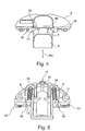
- die in der Anordnung gemäß der
Figuren 1 bis 3 vorhandene Dämpfvorrichtung in perspektivischer Ansicht schräg von oben und - Figur 5:
- die Dämpfvorrichtung gemäß
Figur 4 perspektivisch von unten. - Die
Figuren 1 bis 3 zeigen einen Teil eines erfindungsgemäßen Scharniers für ein an einem Möbelkorpus verschwenkbar anbringbares Möbelteil (nicht gezeigt), wobei ein für eine Anbringung an dem Möbelkorpus ausgebildetes erstes Anschlagteil des Scharniers nicht dargestellt ist. Ein Scharnierarm 1 des Scharniers ist im montierten Zustand des Scharniers mit dem ersten Anschlagteil verbunden, so dass mit dem Scharnier das bewegbare Möbelteil aus einer relativ zum Möbelkorpus geschlossenen Schließposition in eine geöffnete Position und zurück verschwenkt bewegt werden kann. Dabei kommt es zu einer Verschwenkung des bewegbaren Möbelteils gemäß des Doppelpfeils P1 um eine Schwenkachse S. Die Schwenkachse gehört zu einem Schwenklager SL des Scharniers. Der Scharnierarm 1 ist über das Schwenklager SL an dem am bewegbaren Möbelteil festlegbaren zweiten Anschlagteil, das einen Scharniertopf 2 und einen Befestigungsflansch 2a umfasst, gelenkig verbunden. - Die in den
Figuren 1 bis 3 gezeigten Stellungen der Scharnierteile zueinander entspricht im montierten Zustand des Scharniers am Möbel einer relativ zum Möbelkorpus teilweise geöffneten Stellung des bewegbaren Möbelteils, also zwischen einer zum Korpus vollständige geschlossenen und vollständig offenen Möbelteilstellung. - Der Scharniertopf 2 wird zur Montage am bewegbaren Möbelteil in einer am Möbelteil positionsrichtig vorbereiteten Vertiefung bzw. Aufnahme zum Beispiel einem Sackloch eingesetzt und über zwei weitere zum Sackloch seitlich vorhandene Bohrungen, in welche Befestigungszapfen 2b, die unterseitig an dem Befestigungsflansch 2a vorhanden sind, eingreifen, positionsrichtig mittels in die Befestigungszapfen 2b von oben eingreifenden Schrauben 14 fixiert.
- In einem zur Schwenkachse S gegenüberliegenden vertieften Bereich im Scharniertopf 2 ist eine Grundplatte 6 einer Dämpfvorrichtung 3 angepasst an die Halbkreisform einer Innenwandung der Vertiefung des Scharniertopfs 2, so dass die Dämpfvorrichtung 3 im vertieften Bereich des Scharniertopfs 2 eingesetzt ist. Dabei liegt ein halbkreisförmiger Außenabschnitt der Grundplatte 6 an einer von oben auf den vertieften Scharniertopf 2 betrachtet halbkreisförmigen Innenwandung 2c des Scharniertopfs 2 an. Anschließend an die bogenförmige Innenwandung 2c sind zwei nach innen gehende Vorsprünge 2d in der Wandung des Scharniertopfs 2 ausgebildet, an welchen sich die Dämpfvorrichtung 3 jeweils abstützt und so positionsfest im Scharniertopf 2 leicht eingeklemmt gehalten ist. Unterseitig sitzt die Dämpfvorrichtung 3 auf einer Bodenfläche der Vertiefung des Scharniertopfs 2 auf. Die Dämpfvorrichtung 3 kann demgemäß von oben in den Scharniertopf 2 ohne Probleme z. B. von Hand bei der Herstellung des Scharniers klemmend eingesetzt werden.
- Bei einer Möbelteil-Verschwenkbewegung mit dem montierten Scharnier wirkt zudem eine Bügelfeder 15, insbesondere als Schließautomatik, um federkraftbeaufschlagt das bewegbare Möbelteil in eine zum Korpus angeklappte Schließstellung zu bringen bzw. dort zu halten. Gegen diese Kraft bzw. gegen eine gesamt wirkende Schließbewegungskraft bzw. Schließenergie des sich schließenden Möbelteils, das ggf. mit Schwung von einer Bedienperson zugestoßen wird, wirkt die Dämpfvorrichtung 3 beim Schließen des Möbelteils und bremst die Schließbewegung des Möbelteils auf dessen letztem Teilweg ab.
- Mit dem Erreichen des letzten Teilwegs bei der Schließbewegung des bewegbaren Möbelteils kommt dabei ein Auflagepunkt 4 bzw. ein Auflagebereich am Scharnierarm 1, der ja positionsfest zum Möbelkorpus vorhanden ist, in Kontakt mit einem Teil des beim Verschwenken räumlich sich bewegenden Teils des Scharniers. Der Kontakt des Auflagepunkts 4 findet mit einem Kontaktteil der Dämpfvorrichtung 3 statt, wobei das Kontaktteil an einem Dämpfergehäuse 5 der Dämpfvorrichtung 3 ausgebildet ist. Das Dämpfergehäuse 5 ist relativ zur Grundplatte 6 der Dämpfvorrichtung 3 gemäß Doppelpfeil P2 in
Figur 4 hin- und her geführt gegen einen Dämpfwiderstand verschiebbar, wobei in denFiguren 4 und 5 eine gegenüber der Grundplatte 6 maximal herausbewegte Position des Dämpfergehäuses 5 gezeigt ist. Das Dämpfergehäuse 5 bildet den vorderen Abschnitt eines Dämpferzylinders 7, der an Führungsstegen 16 der Grundplatte 6 geführt ist. - Zudem ist der Dämpferzylinder 7 gegenüber der Grundplatte 6 über Federn 8, 9 vorgespannt in einer ausgefahrenen Anschlagposition gemäß
Figur 4 und 5 gehalten, wobei seitlich am Dämpferzylinder 7 abstehende Nasen 17 gegen mechanische Anschläge 18 an der Grundplatte 6 andrücken. Beim Dämpfvorgang kann der Dämpferzylinder 7 unter Zusammendrücken der Federn 8, 9 aus seiner überstehenden Position an der Grundplatte 6 nach innen gedrückt werden. Dabei kommt es zudem zu einer Relativbewegung eines in einem Innen- bzw. Hohlvolumen des Dämpferzylinders 7 eingreifenden Kolbens (nicht ersichtlich) an dem eine Kolbenstange 10 fest vorhanden ist und mit ihrem feien Ende an einer Kolbenstangenfixierung 11 an der Grundplatte 6 fixiert ist. Der Dämpferzylinder 7 und der Kolben samt Kolbenstange 10 wirken wie ein an sich bekannter Kolben-Zylinder-Dämpfer bzw. Fluiddämpfer und wird daher nicht weiter erklärt. - In
Figur 5 ist ein unterseitig an der Grundplatte 6 anbringbarer Stellstift nicht dargestellt, welcher in einer Stellstiftaufnahme 12 bzw. 13 einsetzbar ist und dann den vollständig eingeschobenen Dämpferzylinder 7 festhält gegen die Kraft der Federn 8 und 9. Damit lässt sich die Dämpfwirkung der Dämpfvorrichtung 3 komplett inaktivieren solange der Stellstift eingesetzt ist. -
- 1
- Scharnierarm
- 2
- Scharniertopf
- 2a
- Befestigungsflansch
- 2b
- Befestigungszapfen
- 2c
- Innenwandung
- 2d
- Vorsprung
- 3
- Dämpfvorrichtung
- 4
- Auflagepunkt
- 5
- Dämpfergehäuse
- 6
- Grundplatte
- 7
- Dämpferzylinder
- 8,9
- Feder
- 10
- Kolbenstange
- 11
- Kolbenstangenfixierung
- 12,13
- Stellstiftaufnahme
- 14
- Schraube
- 15
- Bügelfeder
- 16
- Führungssteg
- 17
- Nase
- 18
- Anschlag
Claims (12)
- Vorrichtung für ein bewegbares Möbelteil, insbesondere für eine Tür, Klappe oder Schublade, wobei die Vorrichtung ein an einem Korpus anbringbares erstes Anschlagteil aufweist, welches über einen Gelenkmechanismus mit einem am bewegbaren Möbelteil anbringbaren zweiten Anschlagteil für ein Verschwenken des bewegbaren Möbelteils verbunden ist, und wobei im montierten Zustand der Vorrichtung zur Dämpfung der Relativbewegung von Vorrichtungsteilen der Vorrichtung beim Verschwenken des bewegbaren Möbelteils eine Dämpfvorrichtung vorhanden ist, welche ein Dämpfergehäuse und ein am Dämpfergehäuse aufgenommenes Innenteil umfasst, die zueinander bewegbar sind, und das Dämpfergehäuse oder das Innenteil als Kontaktteil dient, welches für eine Dämpfung mit einem beim Verschwenken des Möbelteils bewegbaren Abschnitt der Vorrichtung zumindest zeitweise in Kontakt gelangt, und eine Einstellanordnung vorgesehen ist, mit welcher eine Einstellung der mit der Dämpfvorrichtung bereitgestellten Dämpfung vornehmbar ist, dadurch gekennzeichnet, dass die Einstellanordnung ausgebildet ist, für eine Einstellung einer gewünschten Dämpfung eine Anbringposition der Dämpfvorrichtung im montierten Zustand an der Vorrichtung veränderbar vorzugeben, wobei die Dämpfvorrichtung in der vorgegebenen Anbringposition an der Vorrichtung festgelegt ist.
- Vorrichtung nach dem Oberbegriff des Anspruchs 1, insbesondere nach Anspruch 1, dadurch gekennzeichnet, dass die Einstellanordnung derart ausgebildet ist, eine Position eines Kontaktelements einer Kontaktstelle der Vorrichtung, über welche die Vorrichtung für eine Dämpfung zeitweise mit dem Kontaktteil der Dämpfvorrichtung in Anlage bringbar ist, zur verbleibenden Vorrichtung verlagerbar vorzugeben.
- Vorrichtung nach Anspruch 2, dadurch gekennzeichnet, dass die Vorgabe der Position des Kontaktelements der Kontaktstelle der Vorrichtung über Stellmittel erfolgt, welche eine Schraubenanordnung umfassen.
- Vorrichtung nach einem der vorhergehenden Ansprüche, dadurch gekennzeichnet, dass die Dämpfvorrichtung derart ausgebildet ist, dass eine auf die Dämpfvorrichtung bezogene Relativstellung des Kontaktteils in einer Bereitschaftsposition, in welcher die Kontaktstelle der Vorrichtung in Anlage an dem Kontaktteil kommt, unabhängig von der festlegbaren Anbringposition der Dämpfvorrichtung an der Vorrichtung erhalten bleibt.
- Vorrichtung nach einem der vorhergehenden Ansprüche, dadurch gekennzeichnet, dass die Dämpfvorrichtung derart ausgebildet ist, dass ein eingerichteter möglicher Bewegungsweg des Kontaktteils relativ zu weiteren Teilen der Dämpfvorrichtung unabhängig von der festlegbaren Anbringposition des Dämpfergehäuses an der Vorrichtung erhalten bleibt.
- Vorrichtung nach einem der vorhergehenden Ansprüche, dadurch gekennzeichnet, dass die Dämpfvorrichtung derart ausgestaltet ist, dass ein eingerichteter möglicher Bewegungsweg des Kontaktteils relativ zu weiteren Teilen der Dämpfvorrichtung einstellbar ist.
- Vorrichtung nach einem der vorhergehenden Ansprüche, dadurch gekennzeichnet, dass Schaltermittel vorgesehen sind, mit denen die Dämpfvorrichtung regulierbar ist.
- Vorrichtung nach einem der vorhergehenden Ansprüche, dadurch gekennzeichnet, dass die Schaltermittel für deren manuelle Betätigung ausgestaltet sind.
- Vorrichtung nach einem der vorhergehenden Ansprüche, dadurch gekennzeichnet, dass die Dämpfvorrichtung in einem vertieft ausgebildeten Bereich eines Anschlagteils, insbesondere eines Vorrichtungstopfs, positioniert ist.
- Vorrichtung nach einem der vorhergehenden Ansprüche, dadurch gekennzeichnet, dass die Dämpfvorrichtung ein Zylinderbauteil und ein Kolbenbauteil mit Verlängerung umfasst, die bei einer Dämpfung zueinander bewegbar sind.
- Vorrichtung nach einem der vorhergehenden Ansprüche, dadurch gekennzeichnet, dass Federmittel vorgesehen sind, mit welchen auf das Zylinderbauteil oder das Kolbenbauteil eine Federkraft aufbringbar ist, welche bei der Relativbewegung von Zylinderbauteil und Kolbenbauteil wirksam ist.
- Möbel mit einem Korpus und einem an dem Korpus angeschlagenes bewegbares Möbelteil, insbesondere mit einer Tür oder Klappe, dadurch gekennzeichnet, dass eine Vorrichtung nach einem der vorhergehenden Ansprüche vorgesehen ist.
Applications Claiming Priority (1)
| Application Number | Priority Date | Filing Date | Title |
|---|---|---|---|
| DE202010015536U DE202010015536U1 (de) | 2010-11-18 | 2010-11-18 | Vorrichtung für ein bewegbares Möbelteil und Möbel |
Publications (2)
| Publication Number | Publication Date |
|---|---|
| EP2455569A2 true EP2455569A2 (de) | 2012-05-23 |
| EP2455569A3 EP2455569A3 (de) | 2014-07-02 |
Family
ID=45092095
Family Applications (1)
| Application Number | Title | Priority Date | Filing Date |
|---|---|---|---|
| EP20110009074 Withdrawn EP2455569A3 (de) | 2010-11-18 | 2011-11-15 | Vorrichtung für ein bewegbares Möbelteil und Möbel |
Country Status (3)
| Country | Link |
|---|---|
| US (1) | US20120126677A1 (de) |
| EP (1) | EP2455569A3 (de) |
| DE (1) | DE202010015536U1 (de) |
Cited By (2)
| Publication number | Priority date | Publication date | Assignee | Title |
|---|---|---|---|---|
| DE102016122879A1 (de) | 2016-11-28 | 2018-05-30 | Karl Simon Gmbh & Co. Kg | Magnetverschluss |
| US10344517B2 (en) | 2015-10-15 | 2019-07-09 | Hardware Resources, Inc. | Soft close device for compact hinges |
Families Citing this family (9)
| Publication number | Priority date | Publication date | Assignee | Title |
|---|---|---|---|---|
| ITMI20121122A1 (it) * | 2012-06-26 | 2013-12-27 | Salice Arturo Spa | Cerniera decelerata per mobili |
| ITMI20121837A1 (it) * | 2012-10-29 | 2014-04-30 | Salice Arturo Spa | Cerniera per mobili con dispositivo di decelerazione disattivabile |
| CN103243993B (zh) * | 2013-05-09 | 2015-06-03 | 伍志勇 | 家具铰链阻尼力的控制装置 |
| CN203394222U (zh) * | 2013-06-24 | 2014-01-15 | 广东泰明金属制品有限公司 | 家具用铰链 |
| CN103953236A (zh) * | 2014-04-30 | 2014-07-30 | 伍志勇 | 一种家具用的静音铰链 |
| DE102015015168B3 (de) | 2015-11-26 | 2016-09-01 | Günther Zimmer | Dämpferbaugruppe eines Topfscharniers sowie Topfscharnier mit dieser |
| US11149481B2 (en) * | 2016-08-19 | 2021-10-19 | Samet Kalip Ve Maden Esya San. Ve Tic A.S. | Furniture hinge |
| TWI625454B (zh) * | 2017-06-08 | 2018-06-01 | 川湖科技股份有限公司 | 鉸鏈 |
| US11242706B2 (en) * | 2019-07-30 | 2022-02-08 | Grass America Inc. | Removable damping mechanism and cabinet hinge assembly including same |
Citations (1)
| Publication number | Priority date | Publication date | Assignee | Title |
|---|---|---|---|---|
| DE202004016396U1 (de) * | 2004-10-21 | 2005-01-05 | Julius Blum Gmbh | Dämpferanordnung |
Family Cites Families (8)
| Publication number | Priority date | Publication date | Assignee | Title |
|---|---|---|---|---|
| US2940116A (en) * | 1957-02-22 | 1960-06-14 | Salice Arturo | Circular shaped double-acting spring hinge, especially for doors of furniture |
| DE202004019238U1 (de) * | 2004-12-10 | 2005-02-17 | MEPLA-WERKE LAUTENSCHLäGER GMBH & CO. KG | Möbel-Scharnier mit Schließ- und Öffnungsvorrichtung |
| DE202005011752U1 (de) * | 2005-07-22 | 2006-11-30 | Hettich-Oni Gmbh & Co. Kg | Dämpfungselement |
| US7552509B2 (en) * | 2006-11-15 | 2009-06-30 | King Slide Works Co., Ltd. | Hinge buffer device |
| US8505165B2 (en) * | 2008-01-22 | 2013-08-13 | Grass America, Inc. | Damping mechanism for cabinet hinge assembly |
| AT509720B1 (de) * | 2010-08-23 | 2011-11-15 | Blum Gmbh Julius | Dämpfvorrichtung für möbelteile |
| DE202012003508U1 (de) * | 2012-04-05 | 2013-07-08 | Grass Gmbh | Vorrichtung für ein bewegbares Möbelteil und Möbel |
| US8650711B1 (en) * | 2013-01-04 | 2014-02-18 | King Slide Works Co., Ltd. | Hinge assembly with damping device |
-
2010
- 2010-11-18 DE DE202010015536U patent/DE202010015536U1/de not_active Expired - Lifetime
-
2011
- 2011-11-15 EP EP20110009074 patent/EP2455569A3/de not_active Withdrawn
- 2011-11-15 US US13/296,669 patent/US20120126677A1/en not_active Abandoned
Patent Citations (1)
| Publication number | Priority date | Publication date | Assignee | Title |
|---|---|---|---|---|
| DE202004016396U1 (de) * | 2004-10-21 | 2005-01-05 | Julius Blum Gmbh | Dämpferanordnung |
Cited By (2)
| Publication number | Priority date | Publication date | Assignee | Title |
|---|---|---|---|---|
| US10344517B2 (en) | 2015-10-15 | 2019-07-09 | Hardware Resources, Inc. | Soft close device for compact hinges |
| DE102016122879A1 (de) | 2016-11-28 | 2018-05-30 | Karl Simon Gmbh & Co. Kg | Magnetverschluss |
Also Published As
| Publication number | Publication date |
|---|---|
| DE202010015536U1 (de) | 2012-03-01 |
| US20120126677A1 (en) | 2012-05-24 |
| EP2455569A3 (de) | 2014-07-02 |
Similar Documents
| Publication | Publication Date | Title |
|---|---|---|
| DE202010015536U1 (de) | Vorrichtung für ein bewegbares Möbelteil und Möbel | |
| EP3889381B1 (de) | Möbel | |
| EP2286048B1 (de) | Dämpfungseinrichtung für möbeltüren | |
| EP3143228B1 (de) | Scharnier | |
| AT517377B1 (de) | Möbelscharnier | |
| EP1223282B1 (de) | Hebevorrichtung für eine zweiflügelige Faltklappe | |
| EP2142045B1 (de) | Möbel und vorrichtung zum ausstossen eines möbelteils | |
| EP1802833B1 (de) | Scharnier für bewegliche Möbelteile | |
| AT502487B1 (de) | Dämpferanordnung | |
| WO2013149632A1 (de) | Vorrichtung für ein bewegbares möbelteil und möbel | |
| EP2609272A1 (de) | Möbeldämpfer | |
| EP2268882A1 (de) | Möbelscharnier | |
| DE102011115662B4 (de) | Verstellbare automatische Rückstellvorrichtung mit Pufferwirkung für eine Schiebetür | |
| AT521170A4 (de) | Möbelbeschlag | |
| EP3625415B1 (de) | Klappenlager mit einer einstellhilfe | |
| DE202005011752U1 (de) | Dämpfungselement | |
| EP2251514B1 (de) | Deckelsteller | |
| AT9710U1 (de) | Möbel-scharnier mit schliess- und öffnungsvorrichtung | |
| DE202006021048U1 (de) | Ausstoßvorrichtung für ein bewegbares Möbelteil | |
| EP4466435B1 (de) | Möbel | |
| EP3147440B1 (de) | Einzugvorrichtung für schiebetüren | |
| DE202010002232U1 (de) | Beschlaganordnung für einen Eckschrank | |
| WO2018208240A1 (de) | Scharnier mit klemmschutz und verfahren zur verstellung von befestigungsteilen eines scharniers | |
| WO2023138944A1 (de) | Möbel | |
| WO2008135155A1 (de) | Möbelscharnier mit eienr dämpfungsvorrichtung |
Legal Events
| Date | Code | Title | Description |
|---|---|---|---|
| PUAI | Public reference made under article 153(3) epc to a published international application that has entered the european phase |
Free format text: ORIGINAL CODE: 0009012 |
|
| AK | Designated contracting states |
Kind code of ref document: A2 Designated state(s): AL AT BE BG CH CY CZ DE DK EE ES FI FR GB GR HR HU IE IS IT LI LT LU LV MC MK MT NL NO PL PT RO RS SE SI SK SM TR |
|
| AX | Request for extension of the european patent |
Extension state: BA ME |
|
| PUAL | Search report despatched |
Free format text: ORIGINAL CODE: 0009013 |
|
| AK | Designated contracting states |
Kind code of ref document: A3 Designated state(s): AL AT BE BG CH CY CZ DE DK EE ES FI FR GB GR HR HU IE IS IT LI LT LU LV MC MK MT NL NO PL PT RO RS SE SI SK SM TR |
|
| AX | Request for extension of the european patent |
Extension state: BA ME |
|
| RIC1 | Information provided on ipc code assigned before grant |
Ipc: E05F 5/00 20060101AFI20140527BHEP |
|
| 17P | Request for examination filed |
Effective date: 20141219 |
|
| RBV | Designated contracting states (corrected) |
Designated state(s): AL AT BE BG CH CY CZ DE DK EE ES FI FR GB GR HR HU IE IS IT LI LT LU LV MC MK MT NL NO PL PT RO RS SE SI SK SM TR |
|
| RAP1 | Party data changed (applicant data changed or rights of an application transferred) |
Owner name: GRASS AMERICA, INC. |
|
| 17Q | First examination report despatched |
Effective date: 20150420 |
|
| STAA | Information on the status of an ep patent application or granted ep patent |
Free format text: STATUS: EXAMINATION IS IN PROGRESS |
|
| STAA | Information on the status of an ep patent application or granted ep patent |
Free format text: STATUS: THE APPLICATION IS DEEMED TO BE WITHDRAWN |
|
| 18D | Application deemed to be withdrawn |
Effective date: 20161115 |