EP2455193A1 - Sensing head for waste from stripping - Google Patents
Sensing head for waste from stripping Download PDFInfo
- Publication number
- EP2455193A1 EP2455193A1 EP11189903A EP11189903A EP2455193A1 EP 2455193 A1 EP2455193 A1 EP 2455193A1 EP 11189903 A EP11189903 A EP 11189903A EP 11189903 A EP11189903 A EP 11189903A EP 2455193 A1 EP2455193 A1 EP 2455193A1
- Authority
- EP
- European Patent Office
- Prior art keywords
- support
- head according
- sleeves
- tool
- movable elements
- Prior art date
- Legal status (The legal status is an assumption and is not a legal conclusion. Google has not performed a legal analysis and makes no representation as to the accuracy of the status listed.)
- Withdrawn
Links
Images
Classifications
-
- B—PERFORMING OPERATIONS; TRANSPORTING
- B24—GRINDING; POLISHING
- B24C—ABRASIVE OR RELATED BLASTING WITH PARTICULATE MATERIAL
- B24C9/00—Appurtenances of abrasive blasting machines or devices, e.g. working chambers, arrangements for handling used abrasive material
- B24C9/003—Removing abrasive powder out of the blasting machine
Definitions
- the present invention relates to the technical field of stripping a surface in the general sense on which acts a pickling medium of all kinds such as gaseous, liquid and / or solid.
- the object of the invention relates more specifically to the capture of residues from the pickling operation.
- the object of the invention finds particularly advantageous applications in the field of the capture of residues obtained as a result of the projection on the surface of an object to be treated, an abrasive flow such as a fluid flow, a gaseous flow comprising solid particles or a liquid flow, in order to clean the object by the erosion of the surface particles, caused by the stripping flux.
- an abrasive flow such as a fluid flow, a gaseous flow comprising solid particles or a liquid flow
- Another application of the invention relates to the capture of residues resulting from a sanding operation of a surface.
- a head equipped with a stripping tool comprises a support inside which is mounted a pickling tool such as a sanding tool or a nozzle for projecting a stripping flux.
- This support delimits a closed enclosure with the exception of an opening through which the pickling tool acts. Projection of the stripping flux on the surface to be treated or sanding of this surface causes the appearance of residues from the abrasive mixed with the waste from the etched surface.
- this stripping operation takes place either in a closed cabin or in the open air.
- a closed cabin avoids the dispersion into the atmosphere of the residues that are recovered or possibly reused.
- the use of a cabin remains limited for objects of relatively small dimensions and easy to handle.
- a stripping operation in the open air obviously causes a dispersion of the residues in the atmosphere, which leads to serious drawbacks in terms of pollution.
- the state of the art has proposed to equip the head, a suction circuit to prevent the dispersion of these residues in the atmosphere.
- the patent US 5,441,443 discloses a pickup head having an opening through which the pickling flow is projected, this opening being in communication with a source designed to suck the residues resulting from the pickling operation.
- the opening of this sensing head is bordered by an elastomer seal intended to come into contact with the surface to be treated in order to confine the residues.
- capture heads have a relatively large footprint leading to a difficulty to correctly carry out the stripping operation and in particular the operation of recovering residues for a surface to treat difficult to access or presenting shapes whose profile changes abruptly. Indeed, for this type of parts to be treated, the capture head is not in complete contact with the treated surface so that a large part of the residues are not confined and sucked.
- the patent application EP 0 384 873 describes a pickling tool comprising a pickup head made in the form of brushes connected to a movable bellows.
- a pickup head made in the form of brushes connected to a movable bellows.
- such a capture head does not allow to confine the residues for a surface whose profile has variations.
- the present invention aims to overcome the disadvantages of the prior art by providing a new capture head designed to allow to confine the residues of the pickling operation whatever the shape or profile of the surface to be treated.
- the sensing head comprises a support inside which is intended to be mounted a stripping tool, the support defining an outlet opening through which the pickling tool acts.
- the sensing head comprises at least one series of moving elements extending parallel to each other over the entire periphery of the support defining the opening, being resiliently biased in extension relative to the support for together forming a protruding barrier of confinement of adjustable shape and adjustable height between a retracted position and an extreme position of exit.
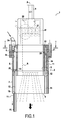
- the object of the invention relates to a sensor head 1 comprising a body or carrier 2 inside which is intended to be mounted by any suitable means, a grinding tool B, as a sanding tool or a jet nozzle of a medium or a pickling flux F of any type known per se, of a gaseous, liquid and / or solid nature.
- the support 2 delimits internally an enclosure 3 communicating with the outside through an opening 4 through which the pickling flux F exits .
- the support 2 has a tubular shape of longitudinal axis of symmetry A comprising a ferrule 5 at one end of which is fixed a cover 6 while the other end of the shell 5 is provided with a skirt 7 defining the actual opening 4.
- the opening 4 has a circular cross section and the stripping tool is a projection nozzle B of a stripping flux F.
- the nozzle B is mounted on the support 2 so as to allow the discharge of the pickling flow F through the opening 4.
- the body B 1 of the pickling nozzle B is fixed to the cover 6 so that the nozzle B extends inside the enclosure 3 with its output located nearby the opening 4 to allow the output of the stripping flux F through this opening.
- the stripping flux F is represented at Fig. 1 as parallel to the axis of the opening 4 but it is clear that this representation is simply schematic since the stripping flow F may have one or more directions different from an axial direction.
- the body B 1 of the nozzle comprises a connection 9 for a connection duct to a production source of the stripping flux.
- the pickling nozzle B extends inside the support 2 by partially occupying the volume of the enclosure 3 so as to delimit between the support 2 and the projection nozzle B, a chamber 3 1 annular whose function will appear more precisely in the following description.
- the nozzle B which is centered on the longitudinal axis of symmetry A, has a substantially tubular shape whose diameter is smaller than the diameter of the support 2 so that this nozzle delimits a chamber 3 1 of substantially annular shape surrounding said nozzle.
- the capture head 1 comprises a series of rigid moving elements 11 extending parallel to each other projecting over the entire periphery of the support 2 delimiting the opening 4, being resiliently biased in 2.
- the movable elements 11 are placed next to one another so as to be substantially in contact with one another so as to form together a confinement barrier of adjustable shape and of adjustable height between one and the other. retracted position (right on the Fig. 1 ) and an extreme exit position (left on the Fig. 1 ).
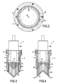
- each movable element 11 is identical and are 40 in number. Of course, the number of movable elements 11 may be different and depends in practice on the length of the circumference of the magnet. 4.
- each movable element 11 comprises a needle or a rod 12 guided in sliding inside a bore 14 arranged in the support 2 and more precisely in the shell 5.
- the bores 14 are arranged next to each other in a circle since the opening 4 is circular in shape.
- Each bore 14 is provided with or without sliding guide inserts for a rod 12 which has in the example illustrated a circular cross section.
- each rod 12 is provided with a sleeve 15 extending outside the guide bores 14.
- the sleeves 15 are thus arranged in a circle and extend inside the skirt 7 2.
- the sleeves 15 are dimensioned so as to be in contact along their length with the two adjacent sleeves 15 .
- each sleeve 15 of preferably circular section is in contact with its generators symmetrically opposite the generatrices of the two sleeves 15 extending on either side of said sleeve.
- the sleeves 15 which together form a kind of comb whose teeth or sleeves 15 extend close to each other to delimit a watertight barrier surrounding the opening 4.
- the sleeves 15 may be provided. are not contiguous to each other while ensuring a function of stopping residues. Thus, the spacing between the sleeves 15 depends on the nature and size of residue.
- the movable elements 11 can be made solely by the rods 12.
- each sleeve 15 is in contact with the skirt 7 via its outer generator farthest from the longitudinal axis of symmetry A.
- Each sleeve 15 comprises a stop 18 cooperating with the support 2 to allow to define the retracted position of the rods.
- each sleeve 15 has a larger diameter than the rod 12 so that its upper edge forms the bearing abutment 18 against the shell 7 as is apparent from the Fig. 1 .
- the movable elements 11 are biased by elastic return means 21 so as to place them in their extreme output position.
- the elastic return means 21 are made by a fluid under pressure acting on all the movable elements 11.
- the bores 14 for guiding the rods 12 open into a chamber 22 distribution arranged in the cover 6 and have in the example shown, an annular shape.
- This distribution chamber 22 is connected by a pipe 24 to a source of fluid pressure.
- the pressure source delivers compressed air as rods biasing fluid 12.
- the rods 12 are mounted in sealed manner inside the bores 14 of the guide so as to be resiliently biased by fluid pressure.
- Each rod 12 is provided with a seal 25 cooperating with the bore 14 and mounted at the end of the rod, opposite that provided with the sleeve 15.
- Each seal 25 acts as a piston on which the fluid pressure acts.
- the movable elements 11 are able to slide between two extreme positions, namely a retracted or retracted position (illustrated on the right to the Fig. 1 ) and an extreme exit position (shown on the left at Fig. 1 ).
- the retracted position of the movable elements 11 is defined by the support of the sleeves 15, by their abutment 18 against the edge of the shell 7. In this retracted position, the sleeves 15 are retracted completely inside the skirt 7. In other words, the free ends of the sleeves 15 are substantially flush with the extreme edge of the skirt 7 which defines the outlet opening 4.
- the length of the sleeves 15 substantially corresponds to the height of the skirt 7. It should be noted that it may be provided to make sleeves 15 of shorter or greater length relative to the length of the skirt 7. Similarly, it may be envisaged to equip the rods 12, sleeves 15 having different lengths each other.
- the extreme position of exit of the movable elements 11 is defined by the abutment of the seals 25 on a shoulder 14 1 presented by the bores 14.
- the movable members 11 protrude with respect to the support 2 and in particular, relative to the skirt 7.
- the sleeves 15 are in contact with the skirt 7.
- the skirt 7 always covers at least a part of the length of the sleeves 15.
- Each movable element 11 is therefore able to occupy any position between these two extreme sliding positions.
- These movable elements 11 are subjected to the elastic return means 21, which urges them so that the movable elements 11 occupy their extreme output position, in the absence of force applied on the free ends of the sleeves 15.
- the sleeves 15 together form a confinement barrier whose height is identical over the entire periphery and corresponds to the height of the sleeves protruding with respect to the opening 4.
- each sleeve 15 has the possibility of axial sliding as a function of the value of the driving force exerted on the free end of the sleeve relative to the force exerted by the elastic return means 21.
- the height of this confinement barrier is therefore variable either identically over the entire circumference, or locally depending on the level of depression of the movable element or elements so that the barrier thus formed has, according to its circumference, a profile or an adjustable shape. Regardless of the depression amount of the sleeves 15, they remain in contact with each other to form together a sealed containment barrier whose inner volume communicates with the thus delimited room 3 1.
- the chamber 3 1 is connected to a suction circuit to allow vacuum residue from the stripping operation and remain blocked by the seal barrier formed by the sleeves 15.
- the chamber 3 1 suction is connected by a suction pipe 26 to a vacuum generator for the recovery and disposal of the confined residues within the volume defined by the sleeves 15.
- the chamber 3 1 communicates with air passages 27 arranged in the support 3 to ensure the balancing of the pressures.
- the pressure source is turned on in order to place the movable elements 11 in their extreme output position.
- the pressurized air elastically urges all the movable elements 11 in extension relative to the support 2.
- the sleeves 15 together form a sealed containment barrier since they are in contact with each other and preferably also with the skirt 7.
- the user applies the head and more precisely the sleeves 15 against the surface S.
- the movable elements 11 are resiliently biased in retraction relative to the support 2, depending on the shape of the surface S to be treated.
- the movable elements 11 are individually subjected to a sliding force whose direction is opposite to that exerted by the elastic return means 21 and whose level depends on the profile of the surface S to be treated. As it appears in Fig. 3 and 4 , it is obtained a self-adaptation of the length of the movable elements 11 which follow the profile of the surface S to be treated.
- the movable elements 11 thanks to the elastic return means 21, all remain in contact with the surface to be treated S so as to constitute together a confinement barrier of the residues obtained. during the stripping operation.
- the use of the vacuum source makes it possible to suck the residues confined by all the mobile elements 11.
- the outlet opening 4 has a circular shape.
- the movable elements 11 will be mounted analogously to the periphery of the outlet opening 4.
- the movable members 11 are biased by elastic return means 21 as a common fluid pressure .
- the movable elements 11 can be resiliently biased by means elastic return 21 different.
- it may be provided to apply elastically extending the movable elements 11 by means of the vacuum prevailing within the suction room 3 1.
- it can be provided to equip each movable member 11 with a spring soliciting extension individually.
- the mobile elements 11 are distributed in a series forming a single confinement barrier surrounding the opening 4.
- the movable elements 11 can be envisaged to distribute the movable elements 11 according to several series to constitute concentric containment barriers between them to increase the confinement capacity according to the application of the capture head according to the invention.
- the movable elements 11 are distributed according to several concentric rings cooperating with each other to increase the confinement function.
- the movable elements 11 and the sleeves 15 are represented in a cylindrical form.
- the movable elements 11 and / or the sleeves 15 may have other shapes than cylindrical or circular.
- the stripping tool B delivers a stripping flux.
- this stripping flux is an ultra-high pressure water flow.
- the stripping flux may be of a different nature.
- the capture head according to the invention can be equipped, as a stripping tool, with a sanding tool acting at the outlet opening 4.
Landscapes
- Engineering & Computer Science (AREA)
- Mechanical Engineering (AREA)
- Cleaning In General (AREA)
Abstract
Description
La présente invention concerne le domaine technique du décapage d'une surface au sens général sur laquelle agit un milieu de décapage de toutes natures telles que gazeux, liquide et/ou solide.The present invention relates to the technical field of stripping a surface in the general sense on which acts a pickling medium of all kinds such as gaseous, liquid and / or solid.
L'objet de l'invention concerne plus précisément le captage des résidus provenant de l'opération de décapage.The object of the invention relates more specifically to the capture of residues from the pickling operation.
L'objet de l'invention trouve des applications particulièrement avantageuses dans le domaine du captage de résidus obtenus à la suite de la projection sur la surface d'un objet à traiter, d'un flux abrasif tel qu'un flux de fluide, un flux gazeux comportant des particules solides ou un flux liquide, afin de nettoyer l'objet par l'érosion des particules de surface, provoquée par le flux de décapage.The object of the invention finds particularly advantageous applications in the field of the capture of residues obtained as a result of the projection on the surface of an object to be treated, an abrasive flow such as a fluid flow, a gaseous flow comprising solid particles or a liquid flow, in order to clean the object by the erosion of the surface particles, caused by the stripping flux.
Une autre application de l'invention concerne le captage de résidus provenant d'une opération de ponçage d'une surface.Another application of the invention relates to the capture of residues resulting from a sanding operation of a surface.
Dans l'état de la technique, il existe de nombreuses formes de réalisation pour une tête équipée d'un outil de décapage. D'une manière générale, une telle tête comporte un support à l'intérieur duquel est monté un outil de décapage tel un outil de ponçage ou une buse de projection d'un flux de décapage. Ce support délimite une enceinte fermée à l'exception d'une ouverture à travers laquelle agit l'outil de décapage. La projection du flux de décapage sur la surface à traiter ou le ponçage de cette surface entraîne l'apparition de résidus provenant de l'abrasif mélangé aux déchets issus de la surface décapée.In the state of the art, there are many embodiments for a head equipped with a stripping tool. In general, such a head comprises a support inside which is mounted a pickling tool such as a sanding tool or a nozzle for projecting a stripping flux. This support delimits a closed enclosure with the exception of an opening through which the pickling tool acts. Projection of the stripping flux on the surface to be treated or sanding of this surface causes the appearance of residues from the abrasive mixed with the waste from the etched surface.
Selon les dimensions et les caractéristiques des objets à traiter, cette opération de décapage a lieu soit dans une cabine fermée, soit à l'air libre. L'utilisation d'une cabine fermée permet d'éviter la dispersion dans l'atmosphère des résidus qui sont récupérés voire éventuellement réutilisés. Bien entendu, l'utilisation d'une cabine reste limitée pour des objets de dimensions relativement réduites et facilement manipulables.Depending on the size and characteristics of the objects to be treated, this stripping operation takes place either in a closed cabin or in the open air. The use of a closed cabin avoids the dispersion into the atmosphere of the residues that are recovered or possibly reused. Of course, the use of a cabin remains limited for objects of relatively small dimensions and easy to handle.
Une opération de décapage à l'air libre entraîne bien évidemment une dispersion des résidus dans l'atmosphère, ce qui conduit à des inconvénients sérieux en termes de pollution. En vue de récupérer les résidus provenant d'une telle opération de décapage, l'état de la technique a proposé d'équiper la tête, d'un circuit d'aspiration permettant d'éviter la dispersion de ces résidus dans l'atmosphère. Par exemple, le brevet
Dans le même sens, le brevet
Il doit être noté que de telles têtes de captage présentent un encombrement relativement important conduisant à une difficulté pour mener correctement à bien l'opération de décapage et en particulier l'opération de récupération des résidus pour une surface à traiter difficile d'accès ou présentant des formes dont le profil change brusquement. En effet, pour ce type de pièces à traiter, la tête de captage n'est pas en contact complètement avec la surface traitée de sorte qu'une bonne partie des résidus ne se trouvent pas confinés et aspirés.It should be noted that such capture heads have a relatively large footprint leading to a difficulty to correctly carry out the stripping operation and in particular the operation of recovering residues for a surface to treat difficult to access or presenting shapes whose profile changes abruptly. Indeed, for this type of parts to be treated, the capture head is not in complete contact with the treated surface so that a large part of the residues are not confined and sucked.
La demande de brevet
La présente invention vise à remédier aux inconvénients de l'art antérieur en proposant une nouvelle tête de captage conçue pour permettre de confiner les résidus de l'opération de décapage quelle que soit la forme ou le profil de la surface à traiter.The present invention aims to overcome the disadvantages of the prior art by providing a new capture head designed to allow to confine the residues of the pickling operation whatever the shape or profile of the surface to be treated.
Pour atteindre un tel objectif, la tête de captage comporte un support à l'intérieur duquel est destinée à être montée un outil de décapage, le support délimitant une ouverture de sortie à travers laquelle agit l'outil de décapage.To achieve such an objective, the sensing head comprises a support inside which is intended to be mounted a stripping tool, the support defining an outlet opening through which the pickling tool acts.
Selon l'invention, la tête de captage comporte au moins une série d'éléments mobiles s'étendant parallèlement les uns à côté des autres sur toute la périphérie du support délimitant l'ouverture, en étant sollicités élastiquement en extension par rapport au support pour former ensemble une barrière saillante de confinement de forme réglable et de hauteur réglable entre une position escamotée et une position extrême de sortie.According to the invention, the sensing head comprises at least one series of moving elements extending parallel to each other over the entire periphery of the support defining the opening, being resiliently biased in extension relative to the support for together forming a protruding barrier of confinement of adjustable shape and adjustable height between a retracted position and an extreme position of exit.
De plus, la tête de captage selon l'invention peut présenter en outre en combinaison au moins l'une et/ou l'autre des caractéristiques additionnelles suivantes :
- l'outil est monté à l'intérieur du support en délimitant entre l'outil et le support, une chambre d'aspiration reliée à un circuit d'aspiration,
- la chambre d'aspiration communique avec l'extérieur du support à l'aide de passages d'admission d'air,
- les éléments mobiles sont pourvus à partir de leurs extrémités libres, de manchons en contact sensiblement les uns à côtés des autres, pour former ensemble une barrière de confinement étanche,
- les éléments mobiles comportent des tiges guidées en coulissement à l'intérieur d'alésages aménagés les uns à côté des autres dans le support, les tiges étant pourvues des manchons s'étendant à l'extérieur des alésages de guidage,
- une jupe d'étanchéité entourant l'ensemble des manchons, en s'étendant à partir du support pour recouvrir au moins une partie de la longueur des manchons,
- les manchons comportent des butées coopérant avec le support pour définir la position escamotée des tiges,
- les éléments mobiles sont sollicités élastiquement par l'intermédiaire d'un fluide sous pression agissant sur l'ensemble des éléments mobiles,
- les alésages de guidage des tiges communiquent avec une enceinte de répartition reliée à une source de pression fluidique, les tiges étant montées de manière étanche à l'intérieur des alésages de guidage de manière à être sollicitées élastiquement par la pression fluidique,
- chaque élément mobile est sollicité par un organe ressort individuel,
- plusieurs séries d'éléments mobiles répartis pour constituer des barrières de confinement concentriques entre elles,
- en tant qu'outil de décapage, un outil de ponçage ou une buse de projection d'un flux de décapage liquide, gazeux et/ou solide.
- the tool is mounted inside the support delimiting between the tool and the support, a suction chamber connected to a suction circuit,
- the suction chamber communicates with the outside of the support with the aid of air intake passages,
- the movable elements are provided from their free ends, sleeves in substantially contact with each other, to form together a sealed containment barrier,
- the movable elements comprise rods which are slidably guided inside bores arranged next to one another in the support, the rods being provided with sleeves extending outside the guide bores,
- a sealing skirt surrounding all the sleeves, extending from the support to cover at least a part of the length of the sleeves,
- the sleeves comprise stops cooperating with the support to define the retracted position of the rods,
- the mobile elements are elastically stressed by means of a fluid under pressure acting on all the moving elements,
- the guide bores of the rods communicate with a distribution chamber connected to a source of fluid pressure, the rods being sealingly mounted inside the guide bores so as to be elastically biased by the fluid pressure,
- each movable element is solicited by an individual spring member,
- several sets of moving elements distributed to constitute concentric containment barriers between them,
- as a stripping tool, a sanding tool or a nozzle for projecting a liquid, gaseous and / or solid stripping flux.
Diverses autres caractéristiques ressortent de la description faite ci-dessous en référence aux dessins annexés qui montrent, à titre d'exemples non limitatifs, des formes de réalisation de l'objet de l'invention.
- La
Figure 1 est une vue en coupe élévation d'un exemple de réalisation d'une tête de captage conforme à l'invention. - La
Figure 2 est une vue en coupe transversale prise sensiblement selon les lignes II-II de laFig. 1 . - Les
Figure 3 et 4 sont des vues montrant la tête de captage conforme à l'invention, en cours de traitement pour deux profils différents de surface à traiter.
- The
Figure 1 is a sectional elevation view of an exemplary embodiment of a sensor head according to the invention. - The
Figure 2 is a cross-sectional view taken substantially along the lines II-II of theFig. 1 . - The
Figure 3 and 4 are views showing the capture head according to the invention, being processed for two different profiles of surface to be treated.
Tel que cela apparaît sur les dessins, l'objet de l'invention concerne une tête de captage 1 comportant un corps ou un support 2 à l'intérieur duquel est destinée à être montée par tout moyen approprié, un outil de décapage B, tel un outil de ponçage ou une buse de projection d'un milieu ou d'un flux de décapage F de tout type connu en soi, de nature gazeux, liquide et/ou solide. Le support 2 délimite intérieurement une enceinte 3 communiquant avec l'extérieur par une ouverture 4 à travers laquelle sort le flux de décapage F. Dans l'exemple illustré, le support 2 présente une forme tubulaire d'axe de symétrie longitudinal A comportant une virole tubulaire 5 à l'une des extrémités de laquelle est fixé un couvercle 6 tandis que l'autre extrémité de la virole 5 est munie d'une jupe 7 délimitant à proprement dit l'ouverture 4. Dans l'exemple illustré, l'ouverture 4 possède une section droite circulaire et l'outil de décapage est une buse B de projection d'un flux de décapage F. As can be seen in the drawings, the object of the invention relates to a sensor head 1 comprising a body or
La buse B est montée sur le support 2 de manière à permettre la sortie du flux de décapage F à travers l'ouverture 4. Dans l'exemple illustré, le corps B1 de la buse de décapage B est fixé au couvercle 6 de sorte que la buse B s'étend à l'intérieur de l'enceinte 3 avec sa sortie située à proximité de l'ouverture 4 pour permettre la sortie du flux de décapage F à travers cette ouverture. Il est à noter que le flux de décapage F est représenté à la
Selon une variante préférée de réalisation, la buse de décapage B s'étend à l'intérieur du support 2 en occupant partiellement le volume de l'enceinte 3 de manière à délimiter entre le support 2 et la buse de projection B, une chambre 31 annulaire dont la fonction apparaîtra plus précisément dans la suite de la description. Dans l'exemple illustré, la buse B qui est centrée sur l'axe de symétrie longitudinale A, présente une forme sensiblement tubulaire dont le diamètre est inférieur au diamètre du support 2 de sorte que cette buse délimite une chambre 31 de forme sensiblement annulaire entourant ladite buse.According to a preferred embodiment, the pickling nozzle B extends inside the
Conformément à l'invention, la tête de captage 1 comporte une série d'éléments mobiles 11 rigides s'étendant parallèlement les uns à côté des autres en saillie sur toute la périphérie du support 2 délimitant l'ouverture 4, en étant sollicité élastiquement en extension par rapport au support 2. En d'autres termes, les éléments mobiles 11 sont placés les uns à côté des autres pour être sensiblement en contact entre eux de manière à former ensemble une barrière de confinement de forme réglable et de hauteur réglable entre une position escamotée (à droite sur la
Dans l'exemple de réalisation illustré, tous les éléments mobiles 11 sont réalisés de manière identique et sont au nombre de 40. Bien entendu, le nombre d'éléments mobiles 11 peut être différent et dépend en pratique de la longueur de la circonférence de l'ouverture 4. Dans l'exemple illustré, chaque élément mobile 11 comporte une aiguille ou une tige 12 guidée en coulissement à l'intérieur d'un alésage 14 aménagé dans le support 2 et plus précisément dans la virole 5. Dans l'exemple illustré, les alésages 14 sont aménagés les uns à côté des autres selon un cercle puisque l'ouverture 4 est de forme circulaire. Chaque alésage 14 est pourvu ou non de moyens rapportés de guidage en coulissement pour une tige 12 qui possède dans l'exemple illustré une section droite circulaire.In the exemplary embodiment illustrated, all the
Dans l'exemple illustré, chaque tige 12 est pourvue d'un manchon 15 s'étendant à l'extérieur des alésages de guidage 14. Les manchons 15 sont ainsi disposés selon un cercle et s'étendent à l'intérieur de la jupe 7 du support 2. Selon une variante préférée de réalisation, les manchons 15 sont dimensionnés de manière à être en contact sur leur longueur avec les deux manchons 15 voisins. Il doit être compris que chaque manchon 15 de section de préférence circulaire est en contact par ses génératrices symétriquement opposées avec les génératrices des deux manchons 15 s'étendant de part et d'autre dudit manchon. Les manchons 15 qui forment ensemble une sorte de peigne dont les dents ou manchons 15 s'étendent à proximité les uns des autres pour délimiter une barrière étanche entourant l'ouverture 4. Il est à noter qu'il peut être prévu que les manchons 15 ne se trouvent pas accolés les uns aux autres tout en assurant une fonction d'arrêt des résidus. Ainsi, l'espacement entre les manchons 15 dépend de la nature et de la taille des résidus. Selon une telle variante, les éléments mobiles 11 peuvent être réalisés uniquement par les tiges 12. In the illustrated example, each
Il doit être noté que les manchons 15 sont entourés par la jupe d'étanchéité 7 qui recouvre toujours une partie de la longueur des manchons 15. De préférence, les manchons 15 sont en contact avec la jupe 7 qui les entoure. Ainsi, chaque manchon 15 est en contact avec la jupe 7 par l'intermédiaire de sa génératrice externe la plus éloignée de l'axe longitudinal de symétrie A. It should be noted that the
Chaque manchon 15 comporte une butée 18 coopérant avec le support 2 pour permettre de définir la position escamotée des tiges. Dans l'exemple illustré, chaque manchon 15 présente un diamètre supérieur à la tige 12 de sorte que son bord supérieur forme la butée d'appui 18 contre la virole 7 comme cela ressort de la
Les éléments mobiles 11 sont sollicités par des moyens de rappel élastique 21 de manière à les placer dans leur position extrême de sortie. Dans l'exemple illustré, les moyens de rappel élastique 21 sont réalisés par un fluide sous pression agissant sur l'ensemble des éléments mobiles 11. Selon cette variante de réalisation, les alésages 14 de guidage des tiges 12 débouchent dans une enceinte 22 de répartition aménagée dans le couvercle 6 et présentent dans l'exemple illustré, une forme annulaire. Cette enceinte de répartition 22 est reliée par une canalisation 24, à une source de pression fluidique. Par exemple, la source de pression délivre de l'air comprimé comme fluide de sollicitation des tiges 12. Les tiges 12 sont montées de manière étanche à l'intérieur des alésages 14 de guidage de manière à pouvoir être sollicitées élastiquement par la pression fluidique. Chaque tige 12 est pourvue d'un joint d'étanchéité 25 coopérant avec l'alésage 14 et montée à l'extrémité de la tige, opposée de celle pourvue du manchon 15. Chaque joint d'étanchéité 25 joue le rôle d'un piston sur lequel agit la pression de fluide.The
Il doit être compris que les éléments mobiles 11 sont aptes à coulisser entre deux positions extrêmes, à savoir une position escamotée ou rentrée (illustrée sur la droite à la
La position extrême de sortie des éléments mobiles 11 est définie par la mise en butée des joints d'étanchéité 25 sur un épaulement 141 présentés par les alésages 14. En position de butée, les éléments mobiles 11 s'étendent en saillie par rapport au support 2 et en particulier, par rapport à la jupe 7. De préférence, dans cette position extrême de sortie, les manchons 15 restent en contact avec la jupe 7. Ainsi, la jupe 7 recouvre toujours au moins une partie de la longueur des manchons 15. The extreme position of exit of the
Chaque élément mobile 11 est donc apte à occuper toute position comprise entre ces deux positions extrêmes de coulissement. Ces éléments mobiles 11 sont soumis aux moyens de rappel élastique 21, qui les sollicitent afin que les éléments mobiles 11 occupent leur position de sortie extrême, en l'absence d'effort appliqué sur les extrémités libres des manchons 15. Dans cette position extrême de sortie, les manchons 15 forment ensemble une barrière de confinement dont la hauteur est identique sur toute la périphérie et correspond à la hauteur des manchons dépassant par rapport à l'ouverture 4. Each
Par ailleurs, chaque manchon 15 possède une possibilité de coulissement axial en fonction de la valeur de l'effort d'enfoncement exercé sur l'extrémité libre du manchon par rapport à l'effort exercé par les moyens de rappel élastique 21. La hauteur de cette barrière de confinement est donc variable soit de manière identique sur toute la circonférence, soit localement en fonction du niveau d'enfoncement du ou des éléments mobiles de sorte que la barrière ainsi constituée présente selon sa circonférence, un profil ou une forme réglable. Quelle que soit la valeur d'enfoncement des manchons 15, ces derniers restent en contact entre eux pour former ensemble une barrière de confinement étanche dont le volume intérieur ainsi délimité communique avec la chambre 31. Furthermore, each
Selon une variante préférée de réalisation, la chambre 31 est reliée à un circuit d'aspiration pour permettre d'aspirer les résidus provenant de l'opération de décapage et restent bloqués par la barrière étanche formée par les manchons 15. La chambre d'aspiration 31 est donc reliée par un conduit d'aspiration 26 à un générateur de dépression permettant la récupération et l'évacuation des résidus confinés à l'intérieur du volume délimité par les manchons 15. Bien entendu, la chambre 31 communique avec des passages d'air 27 aménagés dans le support 3 pour assurer l'équilibrage des pressions.According to a preferred variant embodiment, the
Le fonctionnement de la tête de captage 1 conforme à l'invention découle directement de la description qui précède.The operation of the capture head 1 according to the invention follows directly from the foregoing description.
La source de pression est mise en marche afin de placer les éléments mobiles 11 dans leur position de sortie extrême. L'air sous pression sollicite élastiquement l'ensemble des éléments mobiles 11 en extension par rapport au support 2. Dans cette position de sortie, les manchons 15 forment ensemble une barrière de confinement étanche puisqu'ils sont en contact les uns avec les autres et de préférence aussi avec la jupe 7. The pressure source is turned on in order to place the
En vue de décaper une surface S, l'utilisateur applique la tête et plus précisément les manchons 15 contre la surface S. En raison de l'effort appliqué sur la tête 1, les éléments mobiles 11 sont sollicités élastiquement en rentrée par rapport au support 2, en fonction de la forme de la surface S à traiter. Les éléments mobiles 11 sont soumis individuellement à un effort de coulissement dont le sens est contraire à celui exercé par les moyens de rappel élastique 21 et dont le niveau dépend du profil de la surface S à traiter. Comme cela apparaît aux
Dans l'exemple illustré, l'ouverture de sortie 4 présente une forme circulaire. Bien entendu, il peut être envisagé une ouverture 4 de forme différente. Dans ce cas, les éléments mobiles 11 seront montés de manière analogue à la périphérie de l'ouverture de sortie 4. Par ailleurs dans l'exemple illustré, les éléments mobiles 11 sont sollicités par des moyens de rappel élastique 21 telle une pression fluidique commune. Bien entendu, les éléments mobiles 11 peuvent être sollicités élastiquement par des moyens de rappel élastique 21 différents. Par exemple, il peut être prévu de solliciter élastiquement en extension les éléments mobiles 11 par l'intermédiaire de la dépression régnant à l'intérieur de la chambre d'aspiration 31. Selon un autre exemple de réalisation, il peut être prévu d'équiper chaque élément mobile 11 d'un ressort le sollicitant en extension individuellement.In the illustrated example, the outlet opening 4 has a circular shape. Of course, it can be envisaged an opening 4 of different shape. In this case, the
Il est à noter que dans l'exemple illustré, les éléments mobiles 11 sont répartis en une série formant une seule barrière de confinement entourant l'ouverture 4. Bien entendu, il peut être envisagé de répartir les éléments mobiles 11 selon plusieurs séries pour constituer des barrières de confinement concentriques entre-elles en vue d'augmenter les capacités de confinement en fonction de l'application de la tête de captage selon l'invention. Ainsi, les éléments mobiles 11 sont répartis selon plusieurs couronnes concentriques coopérant entre elles pour accroître la fonction de confinement.It should be noted that in the illustrated example, the
Dans le même sens, les éléments mobiles 11 et les manchons 15 sont représentés sous une forme cylindrique. Bien entendu, les éléments mobiles 11 et/ou les manchons 15 peuvent présenter d'autres formes que cylindriques ou circulaires.In the same direction, the
Dans la description qui précède, l'outil de décapage B délivre un flux de décapage. Selon une application préférée, ce flux de décapage est un flux d'eau en ultra haute pression. Bien entendu, le flux de décapage peut être de nature différente. Dans le même sens, la tête de captage selon l'invention peut être équipé, en tant qu'outil de décapage, d'un outil de ponçage agissant au niveau de l'ouverture de sortie 4. In the above description, the stripping tool B delivers a stripping flux. According to a preferred application, this stripping flux is an ultra-high pressure water flow. Of course, the stripping flux may be of a different nature. In the same direction, the capture head according to the invention can be equipped, as a stripping tool, with a sanding tool acting at the outlet opening 4.
L'invention n'est pas limitée aux exemples décrits et représentés car diverses modifications peuvent y être apportées sans sortir de son cadre.The invention is not limited to the examples described and shown because various modifications can be made without departing from its scope.
Claims (12)
Applications Claiming Priority (1)
| Application Number | Priority Date | Filing Date | Title |
|---|---|---|---|
| FR1059593A FR2967601A1 (en) | 2010-11-22 | 2010-11-22 | CAPTURING HEAD FOR RESIDUES FROM STRIPPING |
Publications (1)
| Publication Number | Publication Date |
|---|---|
| EP2455193A1 true EP2455193A1 (en) | 2012-05-23 |
Family
ID=43901258
Family Applications (1)
| Application Number | Title | Priority Date | Filing Date |
|---|---|---|---|
| EP11189903A Withdrawn EP2455193A1 (en) | 2010-11-22 | 2011-11-21 | Sensing head for waste from stripping |
Country Status (2)
| Country | Link |
|---|---|
| EP (1) | EP2455193A1 (en) |
| FR (1) | FR2967601A1 (en) |
Cited By (1)
| Publication number | Priority date | Publication date | Assignee | Title |
|---|---|---|---|---|
| CN111300283A (en) * | 2020-03-05 | 2020-06-19 | 合肥易知谷机械设计有限公司 | Industrial automatic shot blasting machine |
Families Citing this family (1)
| Publication number | Priority date | Publication date | Assignee | Title |
|---|---|---|---|---|
| CN110186719B (en) * | 2019-05-30 | 2022-04-29 | 北京林业大学 | Sand collecting method and sand collecting device |
Citations (5)
| Publication number | Priority date | Publication date | Assignee | Title |
|---|---|---|---|---|
| EP0384873A1 (en) | 1989-02-24 | 1990-08-29 | Christian Diat | Apparatus for cleaning building-walls |
| EP0396815A1 (en) * | 1989-05-11 | 1990-11-14 | Helmut Fastje | Suction hood for cleaning walls |
| FR2689431A1 (en) * | 1992-04-06 | 1993-10-08 | Teknoson | Method and device especially for ultrasonic hardening of metal parts |
| US5441443A (en) | 1993-11-10 | 1995-08-15 | Nelco Manufacturing Corp. | Apparatus for blast cleaning surfaces disposed at angles within 45 degrees of vertical |
| US5489234A (en) | 1992-01-28 | 1996-02-06 | Sandroid Systems, Inc. | Enhanced recovery system |
-
2010
- 2010-11-22 FR FR1059593A patent/FR2967601A1/en active Pending
-
2011
- 2011-11-21 EP EP11189903A patent/EP2455193A1/en not_active Withdrawn
Patent Citations (5)
| Publication number | Priority date | Publication date | Assignee | Title |
|---|---|---|---|---|
| EP0384873A1 (en) | 1989-02-24 | 1990-08-29 | Christian Diat | Apparatus for cleaning building-walls |
| EP0396815A1 (en) * | 1989-05-11 | 1990-11-14 | Helmut Fastje | Suction hood for cleaning walls |
| US5489234A (en) | 1992-01-28 | 1996-02-06 | Sandroid Systems, Inc. | Enhanced recovery system |
| FR2689431A1 (en) * | 1992-04-06 | 1993-10-08 | Teknoson | Method and device especially for ultrasonic hardening of metal parts |
| US5441443A (en) | 1993-11-10 | 1995-08-15 | Nelco Manufacturing Corp. | Apparatus for blast cleaning surfaces disposed at angles within 45 degrees of vertical |
Cited By (1)
| Publication number | Priority date | Publication date | Assignee | Title |
|---|---|---|---|---|
| CN111300283A (en) * | 2020-03-05 | 2020-06-19 | 合肥易知谷机械设计有限公司 | Industrial automatic shot blasting machine |
Also Published As
| Publication number | Publication date |
|---|---|
| FR2967601A1 (en) | 2012-05-25 |
Similar Documents
| Publication | Publication Date | Title |
|---|---|---|
| EP0777049B1 (en) | Pump connection device | |
| EP3686427B1 (en) | Pump for a liquid product comprising a sealing device and spraying system comprising such a pump | |
| FR3021014A1 (en) | TELESCOPIC WASHING DEVICE | |
| EP3375531B1 (en) | Dispensing device for a fluid and manufacturing method of such a dispensing device | |
| FR2900646A1 (en) | FLUID PRODUCT DISPENSING DEVICE AND METHOD FOR MANUFACTURING MOBILE FLAP DEVICE | |
| EP2455193A1 (en) | Sensing head for waste from stripping | |
| WO2015040181A1 (en) | Method for recovering machining waste by input of energy and machining machine comprising a waste recovery system | |
| FR2838108A1 (en) | Cosmetic fluid dispensing capsule comprises body with dispensing channel and sealing element transverse to channel with passage delimited by sealing lip, and rod with sealing zone complementary to that of channel | |
| WO2014085875A1 (en) | Generic refillable assembly | |
| FR3045422B1 (en) | DEVICE FOR LAUNDRYING A SEAL CORD | |
| EP1893341B1 (en) | Device and installation for spraying coating product comprising a reservoir | |
| EP2058192B1 (en) | Master cylinder with U-shaped gasket | |
| FR2673988A1 (en) | A gate valve with floating stopper seal for high flow rates | |
| EP3526445B1 (en) | Fluid sampling probe | |
| FR2780105A3 (en) | Compressor for use with mains water | |
| EP3969751B1 (en) | Method for assembling a high-pressure precompression pump | |
| FR3065889A1 (en) | FLUID PRODUCT DISPENSING HEAD AND MOLDING ASSEMBLY OF SUCH A HEAD | |
| FR2911835A1 (en) | Windscreen washer liquid tank for motor vehicle, has lateral wall with passage hole for aspirating windscreen washer liquid, and lower wall or floor pan with hollow shape to trap impurities e.g. grit, from windscreen washer liquid | |
| FR3122842A1 (en) | Cleaning device for a mastic bead smoothing wedge carried by a robotic arm | |
| EP1050480A1 (en) | Diaphragm pump comprising a preferential deformation area on at least a part of its periphery, and container incorporating the same | |
| WO2011004125A1 (en) | Gas spring device comprising a dynamic lubrication system | |
| FR3006924A1 (en) | DEVICE FOR CUTTING A FIXING MEANS | |
| FR3102737A1 (en) | Wiper blade assembly, wiper blade adapter and wiper | |
| FR2830785A1 (en) | Method for unlocking a device having two bodies locked by latching, especially a microbiological examination device, comprises using a sheath having portions for insertion between a latching tab on each body and an outer cylindrical wall | |
| EP1338348A1 (en) | Autonomous and portable cleaning device |
Legal Events
| Date | Code | Title | Description |
|---|---|---|---|
| PUAI | Public reference made under article 153(3) epc to a published international application that has entered the european phase |
Free format text: ORIGINAL CODE: 0009012 |
|
| AK | Designated contracting states |
Kind code of ref document: A1 Designated state(s): AL AT BE BG CH CY CZ DE DK EE ES FI FR GB GR HR HU IE IS IT LI LT LU LV MC MK MT NL NO PL PT RO RS SE SI SK SM TR |
|
| AX | Request for extension of the european patent |
Extension state: BA ME |
|
| STAA | Information on the status of an ep patent application or granted ep patent |
Free format text: STATUS: THE APPLICATION IS DEEMED TO BE WITHDRAWN |
|
| 18D | Application deemed to be withdrawn |
Effective date: 20121124 |