EP2455152A1 - Fluid pressure vessel employing filter bags - Google Patents
Fluid pressure vessel employing filter bags Download PDFInfo
- Publication number
- EP2455152A1 EP2455152A1 EP11009162A EP11009162A EP2455152A1 EP 2455152 A1 EP2455152 A1 EP 2455152A1 EP 11009162 A EP11009162 A EP 11009162A EP 11009162 A EP11009162 A EP 11009162A EP 2455152 A1 EP2455152 A1 EP 2455152A1
- Authority
- EP
- European Patent Office
- Prior art keywords
- shell
- closure
- pressure vessel
- bulkhead
- fitting
- Prior art date
- Legal status (The legal status is an assumption and is not a legal conclusion. Google has not performed a legal analysis and makes no representation as to the accuracy of the status listed.)
- Withdrawn
Links
- 239000012530 fluid Substances 0.000 title claims abstract description 20
- 238000007789 sealing Methods 0.000 claims description 8
- 238000003466 welding Methods 0.000 claims description 5
- 238000000034 method Methods 0.000 claims description 3
- 230000000694 effects Effects 0.000 claims description 2
- 238000004519 manufacturing process Methods 0.000 claims description 2
- 238000005266 casting Methods 0.000 claims 9
- 239000000463 material Substances 0.000 description 8
- 238000001914 filtration Methods 0.000 description 7
- 238000005260 corrosion Methods 0.000 description 5
- 230000007797 corrosion Effects 0.000 description 5
- 239000010963 304 stainless steel Substances 0.000 description 2
- 229910000589 SAE 304 stainless steel Inorganic materials 0.000 description 2
- 230000004075 alteration Effects 0.000 description 2
- 238000010276 construction Methods 0.000 description 2
- 238000012986 modification Methods 0.000 description 2
- 230000004048 modification Effects 0.000 description 2
- 229910001220 stainless steel Inorganic materials 0.000 description 2
- 239000010935 stainless steel Substances 0.000 description 2
- 238000004140 cleaning Methods 0.000 description 1
- 238000004891 communication Methods 0.000 description 1
- 238000003780 insertion Methods 0.000 description 1
- 230000037431 insertion Effects 0.000 description 1
- 238000009434 installation Methods 0.000 description 1
- 230000000452 restraining effect Effects 0.000 description 1
- 230000000717 retained effect Effects 0.000 description 1
- XLYOFNOQVPJJNP-UHFFFAOYSA-N water Substances O XLYOFNOQVPJJNP-UHFFFAOYSA-N 0.000 description 1
Images


Classifications
-
- F—MECHANICAL ENGINEERING; LIGHTING; HEATING; WEAPONS; BLASTING
- F17—STORING OR DISTRIBUTING GASES OR LIQUIDS
- F17C—VESSELS FOR CONTAINING OR STORING COMPRESSED, LIQUEFIED OR SOLIDIFIED GASES; FIXED-CAPACITY GAS-HOLDERS; FILLING VESSELS WITH, OR DISCHARGING FROM VESSELS, COMPRESSED, LIQUEFIED, OR SOLIDIFIED GASES
- F17C13/00—Details of vessels or of the filling or discharging of vessels
-
- B—PERFORMING OPERATIONS; TRANSPORTING
- B01—PHYSICAL OR CHEMICAL PROCESSES OR APPARATUS IN GENERAL
- B01D—SEPARATION
- B01D29/00—Filters with filtering elements stationary during filtration, e.g. pressure or suction filters, not covered by groups B01D24/00 - B01D27/00; Filtering elements therefor
- B01D29/50—Filters with filtering elements stationary during filtration, e.g. pressure or suction filters, not covered by groups B01D24/00 - B01D27/00; Filtering elements therefor with multiple filtering elements, characterised by their mutual disposition
- B01D29/52—Filters with filtering elements stationary during filtration, e.g. pressure or suction filters, not covered by groups B01D24/00 - B01D27/00; Filtering elements therefor with multiple filtering elements, characterised by their mutual disposition in parallel connection
-
- B—PERFORMING OPERATIONS; TRANSPORTING
- B01—PHYSICAL OR CHEMICAL PROCESSES OR APPARATUS IN GENERAL
- B01D—SEPARATION
- B01D35/00—Filtering devices having features not specifically covered by groups B01D24/00 - B01D33/00, or for applications not specifically covered by groups B01D24/00 - B01D33/00; Auxiliary devices for filtration; Filter housing constructions
- B01D35/30—Filter housing constructions
-
- B—PERFORMING OPERATIONS; TRANSPORTING
- B01—PHYSICAL OR CHEMICAL PROCESSES OR APPARATUS IN GENERAL
- B01D—SEPARATION
- B01D2201/00—Details relating to filtering apparatus
- B01D2201/04—Supports for the filtering elements
- B01D2201/043—Filter tubes connected to plates
- B01D2201/0446—Filter tubes connected to plates suspended from plates at the upper side of the filter elements
-
- Y—GENERAL TAGGING OF NEW TECHNOLOGICAL DEVELOPMENTS; GENERAL TAGGING OF CROSS-SECTIONAL TECHNOLOGIES SPANNING OVER SEVERAL SECTIONS OF THE IPC; TECHNICAL SUBJECTS COVERED BY FORMER USPC CROSS-REFERENCE ART COLLECTIONS [XRACs] AND DIGESTS
- Y10—TECHNICAL SUBJECTS COVERED BY FORMER USPC
- Y10T—TECHNICAL SUBJECTS COVERED BY FORMER US CLASSIFICATION
- Y10T29/00—Metal working
- Y10T29/49—Method of mechanical manufacture
- Y10T29/4998—Combined manufacture including applying or shaping of fluent material
- Y10T29/49988—Metal casting
Definitions
- the present disclosure relates to fluid pressure vessels of the type containing filter media such as bags for filtering flow of fluid such as water and acqueous solutions employed in systems in which pressurized fluid enters the vessel through an inlet, is filtered through the filtering media such as filter bags, and exits the pressure vessel through an outlet port connected to the fluid system.
- the pressure vessels of this type typically have a closure or lid which is, upon depressurization of the vessel, removable for access to the filter for cleaning or replacement of the filter media.
- pressure vessels of the aforesaid type typically are fabricated of preformed components such as by a combination of cast pieces and sheet formed pieces which are assembled by weldment. This has resulted in a relatively costly arrangement due to the large amount of welding required to join the components in addition to the complexity of fixtures required for positioning the pieces for welding during assembly.
- the present disclosure describes a unique pressure vessel employing fluid filter media for filtering flow between the inlet port and the outlet port with a removable lid or closure for permitting access to the filter media such as filter bags.
- the vessel shell is constructed of a rolled sheet and welded to form a tubular shell with a one-piece cast closure and outlet port welded to one end of the tubular shell.
- a one-piece cast combination bulkhead and rim flange is welded to the opposite end of the tubular shell.
- a one-piece cast inlet port fitting is inserted through an aperture in the tubular shell and connects to a central aperture in the bulkhead and is welded to the bulkhead and shell.
- the inlet port fitting and the outlet port on the one-piece cast closure are each formed with an integral standard process connection, such as a circular flange for attachment to fluid pressure conduits for installation in a fluid system.
- a one-piece cast lid or closure is pivotally attached to the end of the tubular shell over the bulkhead and is releasably clamped thereon to permit opening of the lid for access to the interior of the vessel.
- the space between the bulkhead and lid forms an inlet plenum.
- the bulkhead has additional apertures therein through which are attached filter media, such as bags, which may be readily removed and replaced upon opening of the lid.
- the pressure vessel of the present disclosure thus is comprised of only four pieces secured by weldment on which the removable lid or closure is mounted thereby providing a relatively low cost, simplified construction of the pressure vessel.
- the removable lid is clamped by circular clamp bars; and, in another embodiment, the flange is provided with pivotal attachment lugs for swing bolts and the lid has slotted lugs permitting the bolts to engage the lid lugs for securing the lid to the flange with ring nuts threaded onto the swing bolts.
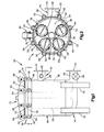
- FIGURE 1 is a front elevation view of an exemplary embodiment of a pressure vessel with removable lid and replaceable filter elements in accordance with the present disclosure
- FIGURE 2 is a section view taken along section indicating lines 2-2 of FIGURE 1 ;
- FIGURE 3 is a right side elevation view of the pressure vessel of FIGURE 1 ;
- FIGURE 4 is a top view of FIGURE 3 ;
- FIGURE 5 is an exploded view of the pressure vessel components prior to assembly by weldment
- FIGURE 6 is a view of the components of FIGURE 5 after assembly
- FIGURE 7 is a perspective view of the one-piece closure and outlet port fitting of the assembly of FIGURE 6 ;
- FIGURE 8 is a perspective view of the inlet port fitting of the assembly of FIGURE 6 ;
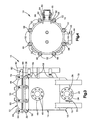
- FIGURE 9 is a top view of the combination bulkhead and flange piece of the assembly of FIGURE 6 ;
- FIGURE 10 is a section view taken along section indicating lines 10-10 of FIGURE 9 ;
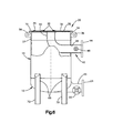
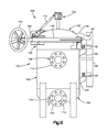
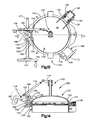
- FIGURE 11 is a front elevation view of another exemplary embodiment of the pressure vessel of the present disclosure.
- FIGURE 12 is a right side elevation view of the assembly of FIGURE 11 ;
- FIGURE 13 is a top view of FIGURE 12 rotated 45° counterclockwise;
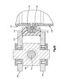
- FIGURE 14 is a partial section view taken along section indicating lines 14-14 of FIGURE 13 ;
- FIGURE 15 is an enlarged view of a portion of FIGURE 14 ;
- FIGURE 16 is a perspective view of the clamp locking bar of the version of FIGURE 11 .
- the first exemplary embodiment of a pressure vessel of the present disclosure is indicated generally at 10 and has a removable lid indicated generally at 12 which is clamped and sealed upon a tubular shell indicated generally at 14.
- the shell 14 has provided thereon and secured thereto, such as by weldment, an end closure indicated generally at 16 and which includes an outlet port fitting 18 formed integrally therewith as a one-piece member.
- a suitable corrosion resistant material such as, for example AISI type 304 stainless steel; however, other suitable castable corrosion resistant materials may be used.
- the closure member 16 is shown as having an outlet port 20 and passage communicating with the interior of the generally cup shaped closure 16.
- an auxiliary fitting and port 18 cast integrally with the member 16 as one piece as denoted by reference numeral 22 which may be employed for ancillary purposes as, for example attachment of a fluid pressure sensor or drain line.
- the fitting 18 has a circular flange 24 which may have a plurality of apertures 26 provided thereabout for attachment to a corresponding flange in the fluid system for which the vessel 10 is to be employed.
- the tubular shell 14 may be formed from flat sheet stock and seam welded to provide the cylindrical tubular configuration illustrated in the drawings.
- the shell 14 may also be formed of corrosion resistant material such as stainless steel such as AISI type 304, although other materials may be used.
- the tubular shell 14 is formed with an aperture 28 through the side thereof for insertion of a fitting as will hereinafter be described.
- the tubular shell has attached to the end thereof opposite the closure 16, a combination bulkhead 32 and annular flange 34 indicated generally at 30 formed as a one-piece member.
- Member 30 also includes a downwardly extending cylindrical wall section 37 which is attached to the end of the shell 14 by weldment.
- the member 30 is cast of corrosion resistant material such as stainless steel such as AISI type 304; however, other materials may be used.
- the relatively thin plate-like bulkhead portion 32 is reinforced with a central web on its underside within the annular outer flange portion 34.
- flange 34 has provided integrally formed therewith a plurality of radially outwardly extending circumferentially spaced attachment lugs 36 cast integrally thereon.
- the bulkhead has a central aperture 40 provided therein which is adapted for connection to an inlet port fitting as will hereinafter be described.
- the flange 34 of member 30 has provided in the upper surface thereof, a circumferential groove 72 which is adapted for receiving therein an annular seal, such as an o-ring (not shown) for sealing against the undersurface of the rim of the lid 12 in a manner known in the art of such pressure vessels.
- an annular seal such as an o-ring (not shown) for sealing against the undersurface of the rim of the lid 12 in a manner known in the art of such pressure vessels.
- a tubular inlet fitting having a generally right angle or elbow configuration is indicated generally at 42 and has formed integrally therewith an annular flange 44 on one end thereof which flange has a plurality of circumferentially spaced apertures 46 provided thereon for attachment thereto.
- the fitting 42 may also include cast integrally therewith a sensing port fitting 48.
- the inlet fitting 42 has the curved end of the fitting denoted by reference numeral 50 inserted through aperture 28 and placed in communication with the central aperture 40 provided in the bulkhead 32 and is secured thereto by suitable weldment; and, the wall of the fitting 42 adjacent the flange 44 is secured in the aperture 28 in the tubular shell by weldment to provide a permanent seal of the fitting in the well of the pressure vessel shell 14 thereby forming the assembly illustrated in FIG. 6 .
- the bulkhead 32 has a plurality of circumferentially spaced apertures 38 formed therethrough which are adapted for each having a filtering media attached thereto which are not shown in FIGS. 9 and 10 but are indicated in dashed line in FIG. 1 and denoted with reference numeral 26.
- the filtering media comprise filter bags contained and supported within a perforated restraining basket (not shown) both of which have an open end secured about the apertures 38 in the bulkhead by hold down rings 39 retained by suitable attachment clips 35 as illustrated in FIGS. 2 and 6 .
- the lid 12 is cast of corrosion resistant material such as AISI type 304 stainless steel; however, other materials may be used.
- Lid 12 has a plurality of radially outwardly extending circumferentially spaced lugs 52 formed thereon integrally therewith into each of which is received a swing bolt 54 pivotally mounted on pins 56 provided in the lugs 36 formed on the flange 34.
- the swing bolts 54 are secured in the lugs 52 by ring nuts 66.
- the shell 14 has attached thereto, such as by weldment, supporting brackets 58 which support a counter balance spring mechanism 60 which has a pivot pin 62 provided thereon.
- a pair of arms 64, 65 extend outwardly from and are formed integrally with the lid 12 and/or hinged on pin 62 for pivotal raising of the lid upon release of the swing bolts 54.
- the closure member 16 has provided thereon disposed about the outer periphery thereof, in circumferentially spaced arrangement, a plurality of mounting lugs 68 which may be integrally cast with the member 16.
- the lugs 68 have attached thereto, as for example by weldment, support members or legs 70 for providing support of the vessel 10 on a horizontal surface.
- FIGS. 11-16 another version of the pressure vessel of the present disclosure is indicated generally at 100 and includes a tubular shell portion indicated generally at 102 and combination upper flange and bulkhead piece indicated generally at 104 and a bottom closure and outlet port integrally formed as one piece indicated generally at 106.
- An inlet fitting similar to the fitting 42 for the version 10, is indicated generally at 108 and is secured through an aperture 110 formed in the side wall of the tubular shell 102 and includes an integral attachment flange 112.
- a one-piece closure and outlet member 106 includes a flange 114 for external attachment thereto and also a signal port 116 formed integrally therewith with a flange 118 adapted for connection externally thereto.
- Inlet fitting 108 also includes a signal port fitting 120 for external connection thereto.
- a removable lid indicated generally at 122 is pivotally attached to the shell 102 as will hereinafter be described.
- shell 102 has a pair of mounting lugs 124, 126 vertically disposed thereon and extending outwardly therefrom and may be attached to the shell by any convenient expedient as for example weldment.
- the lugs 124, 126 have attached thereto a counter balance spring mechanism 128 which may be secured to the lugs 124, 126 by suitable fasteners 130, 132.
- lid 122 has provided thereon a pair of spaced parallel outwardly extending arms 134, 136 which are pivotally engaged with respectively pivot pins 138, 140 extending from mechanism 128.
- the arms 134, 136 may be either formed integrally with the lid 122 as one piece or attached thereto by weldment.
- Lid 122 has attached thereto in the central region thereof and extending vertically upwardly therefrom a pressure relief valve indicated generally at 142 as shown in FIGS. 11-14 .
- the lid 122 is secured to the flange 104 of the vessel by a pair of generally c-shaped clamp bands 144, 146 which are hinged or pivotally connected by a clevis pin 148 each at an end thereof for pivotal opening and closing.
- the clamp bands each have a tapered groove such as groove 150 formed in band 144 as shown in FIGS. 14 and 15 .
- the groove 150 in band 144 and a corresponding groove (not shown) in band 146 each engage an annular tapered surface provided on the rim of the lid 122 as denoted by reference numeral 152 and a tapered surface 154 provided on the flange member 104 for effecting clamping of the lid to the flange member 104.
- annular seal ring 156 is provided in a groove formed around the periphery of the flange member 104 for providing sealing of the lid on the flange 104.
- the clamping bands 144, 146 each have a pair of clevis plates attached to the free ends thereof such as plates 158, 160 attached to clamping band 144 as shown in FIGS. 14 and 15 .
- One of the plates 162 attached to clamping band 146 is illustrated in FIG. 13 .
- the clevis plates 158, 160, 162 each have a hook shaped cutout such as denoted by reference numerals 164 for plate 158 and 166 for plate 162 which are operative to engage clevis pins 168, 170.
- Clevis pin 168 for clamp band 144 is threadedly engaged, in a direction transversely to its pivotal connection to the plates 158, 160, by a threaded hand wheel shaft 172.
- the clevis pins 168, 170 are drawn together closing the clamping bands 144, 146 over the tapered surfaces of the lid and the shelf flange thereby clamping the lid to the shell member 104 and effecting sealing of the lid about the flange by seal ring 156.
- the pressure relief valve 142 has an actuating arm 174 operatively connected thereto which arm is pivotally connected to one end of a link 176 which has its opposite end pivotally connected at 178 to a locking handle 180 which has the end thereof pivotally connected to a lug 182 extending upwardly from the lid 122 by a fastener 184.
- the handle 180 has an aperture 186 formed therein through which the fastener 184 is engaged to permit pivotal movement of the handle in a vertical plane about the lug 182.
- the handle 180 has attached thereto a locking bar 186 which has a pair of spaced cutouts or slots 188, 190 formed along an edge thereof which slots engage respectively, upstanding pins 192, 194 provided on the clevis plates respectively of the clamps 144, 146.
- the slots 188, 190 engage the pins 192, 194 to prevent link 176 from causing arm 174 to open relief valve 142.
- link 176 moves arm 174 to effect opening of the pressure relief valve to relieve the pressure in the vessel prior to rotating the handrail to release the clamping bands 144, 146.
- the version 100 thus employs a pair of c-shaped clamping bands for engaging surfaces on the flange of the vessel and on the lid for effecting closure and sealing thereof.
- the present disclosure describes a unique pressure vessel of the type containing filter media for flow through filtering of fluid in a fluid system such as hydraulic fluid in hydraulically operated equipment or machinery in which the vessel has a removable closure or lid for permitting access to the interior for replacement of the filter media.
- the pressure vessel of the present disclosure has a tubular shell with an annular flange formed on the upper end thereof which flange is cast as a one-piece member having a bulkhead portion and a rim provided for sealing with the lid.
- the bulkhead portion is provided with an inlet aperture for attachment of an inlet fitting through the wall of the shell to permit fluid to enter the vessel and flow to a plenum formed between the lid and the bulkhead and through apertures in the bulkhead to the filter media contained in the shell.
- the lower end of the vessel shell is closed by a one-piece cast closure including an integral outlet port fitting to provide a complete pressure vessel assembly comprised of only four structural members.
- the pressure vessel of the present disclosure thus provides for an improved lower cost and simplified construction for a fluid pressure vessel containing filter media for a flow through filtering.
Landscapes
- Chemical & Material Sciences (AREA)
- Chemical Kinetics & Catalysis (AREA)
- Engineering & Computer Science (AREA)
- Mechanical Engineering (AREA)
- General Engineering & Computer Science (AREA)
- Pressure Vessels And Lids Thereof (AREA)
Abstract
A flow through fluid pressure vessel (10) of the type containing filter bags (26) formed by a tubular shell (14), a one-piece cast bottom closure with an integral outlet port fitting (18) welded to one end of the shell, a one-piece cast combination bulkhead (32) and flange ring (34) welded to the opposite end of the shell, a cast inlet fitting (42) inserted through an aperture (28) in the shell and connected to an inlet opening (40) through the bulkhead and welded to the shell aperture. A cast closure/lid (12) forms an inlet plenum with the bulkhead and is releasably sealed over the flange ring.
Description
- The present disclosure relates to fluid pressure vessels of the type containing filter media such as bags for filtering flow of fluid such as water and acqueous solutions employed in systems in which pressurized fluid enters the vessel through an inlet, is filtered through the filtering media such as filter bags, and exits the pressure vessel through an outlet port connected to the fluid system. The pressure vessels of this type typically have a closure or lid which is, upon depressurization of the vessel, removable for access to the filter for cleaning or replacement of the filter media.
- Heretofore, pressure vessels of the aforesaid type typically are fabricated of preformed components such as by a combination of cast pieces and sheet formed pieces which are assembled by weldment. This has resulted in a relatively costly arrangement due to the large amount of welding required to join the components in addition to the complexity of fixtures required for positioning the pieces for welding during assembly.
- Thus, it has been desired to provide a way or means of fabricating a fluid pressure vessel employing removable filter media with a lid or closure which is readily removable for access to the filter media and which has a significantly reduced manufacturing cost and yet is capable of maintaining the vessel integrity for extended periods of time required in the fluid system applications for which the vessel is intended.
- The present disclosure describes a unique pressure vessel employing fluid filter media for filtering flow between the inlet port and the outlet port with a removable lid or closure for permitting access to the filter media such as filter bags. The vessel shell is constructed of a rolled sheet and welded to form a tubular shell with a one-piece cast closure and outlet port welded to one end of the tubular shell. A one-piece cast combination bulkhead and rim flange is welded to the opposite end of the tubular shell. A one-piece cast inlet port fitting is inserted through an aperture in the tubular shell and connects to a central aperture in the bulkhead and is welded to the bulkhead and shell. The inlet port fitting and the outlet port on the one-piece cast closure are each formed with an integral standard process connection, such as a circular flange for attachment to fluid pressure conduits for installation in a fluid system. A one-piece cast lid or closure is pivotally attached to the end of the tubular shell over the bulkhead and is releasably clamped thereon to permit opening of the lid for access to the interior of the vessel. The space between the bulkhead and lid forms an inlet plenum. The bulkhead has additional apertures therein through which are attached filter media, such as bags, which may be readily removed and replaced upon opening of the lid. The pressure vessel of the present disclosure thus is comprised of only four pieces secured by weldment on which the removable lid or closure is mounted thereby providing a relatively low cost, simplified construction of the pressure vessel. In one embodiment, the removable lid is clamped by circular clamp bars; and, in another embodiment, the flange is provided with pivotal attachment lugs for swing bolts and the lid has slotted lugs permitting the bolts to engage the lid lugs for securing the lid to the flange with ring nuts threaded onto the swing bolts.
-
FIGURE 1 is a front elevation view of an exemplary embodiment of a pressure vessel with removable lid and replaceable filter elements in accordance with the present disclosure; -
FIGURE 2 is a section view taken along section indicating lines 2-2 ofFIGURE 1 ; -
FIGURE 3 is a right side elevation view of the pressure vessel ofFIGURE 1 ; -
FIGURE 4 is a top view ofFIGURE 3 ; -
FIGURE 5 is an exploded view of the pressure vessel components prior to assembly by weldment; -
FIGURE 6 is a view of the components ofFIGURE 5 after assembly; -
FIGURE 7 is a perspective view of the one-piece closure and outlet port fitting of the assembly ofFIGURE 6 ; -
FIGURE 8 is a perspective view of the inlet port fitting of the assembly ofFIGURE 6 ; -
FIGURE 9 is a top view of the combination bulkhead and flange piece of the assembly ofFIGURE 6 ; -
FIGURE 10 is a section view taken along section indicating lines 10-10 ofFIGURE 9 ; -
FIGURE 11 is a front elevation view of another exemplary embodiment of the pressure vessel of the present disclosure; -
FIGURE 12 is a right side elevation view of the assembly ofFIGURE 11 ; and, -
FIGURE 13 is a top view ofFIGURE 12 rotated 45° counterclockwise; -
FIGURE 14 is a partial section view taken along section indicating lines 14-14 ofFIGURE 13 ; -
FIGURE 15 is an enlarged view of a portion ofFIGURE 14 ; and, -
FIGURE 16 is a perspective view of the clamp locking bar of the version ofFIGURE 11 . - Referring to
FIGS. 1-4 , the first exemplary embodiment of a pressure vessel of the present disclosure is indicated generally at 10 and has a removable lid indicated generally at 12 which is clamped and sealed upon a tubular shell indicated generally at 14. Theshell 14 has provided thereon and secured thereto, such as by weldment, an end closure indicated generally at 16 and which includes an outlet port fitting 18 formed integrally therewith as a one-piece member. In the present practice, it has been found satisfactory to cast theclosure member 16 of a suitable corrosion resistant material such as, for example AISI type 304 stainless steel; however, other suitable castable corrosion resistant materials may be used. - Referring to
FIGS. 5-7 , theclosure member 16 is shown as having anoutlet port 20 and passage communicating with the interior of the generally cup shapedclosure 16. In the present practice, it has been found satisfactory to provide an auxiliary fitting andport 18 cast integrally with themember 16 as one piece as denoted byreference numeral 22 which may be employed for ancillary purposes as, for example attachment of a fluid pressure sensor or drain line. Thefitting 18 has acircular flange 24 which may have a plurality ofapertures 26 provided thereabout for attachment to a corresponding flange in the fluid system for which thevessel 10 is to be employed. - In the present practice, the
tubular shell 14 may be formed from flat sheet stock and seam welded to provide the cylindrical tubular configuration illustrated in the drawings. Theshell 14 may also be formed of corrosion resistant material such as stainless steel such as AISI type 304, although other materials may be used. Thetubular shell 14 is formed with anaperture 28 through the side thereof for insertion of a fitting as will hereinafter be described. - Referring to
FIGS. 5 ,6 ,9 and 10 , the tubular shell has attached to the end thereof opposite theclosure 16, acombination bulkhead 32 andannular flange 34 indicated generally at 30 formed as a one-piece member.Member 30 also includes a downwardly extendingcylindrical wall section 37 which is attached to the end of theshell 14 by weldment. In the present practice, themember 30 is cast of corrosion resistant material such as stainless steel such as AISI type 304; however, other materials may be used. The relatively thin plate-like bulkhead portion 32 is reinforced with a central web on its underside within the annularouter flange portion 34. In theembodiment 10,flange 34 has provided integrally formed therewith a plurality of radially outwardly extending circumferentially spacedattachment lugs 36 cast integrally thereon. The bulkhead has acentral aperture 40 provided therein which is adapted for connection to an inlet port fitting as will hereinafter be described. - Referring to
FIGS. 9 and 10 , theflange 34 ofmember 30 has provided in the upper surface thereof, acircumferential groove 72 which is adapted for receiving therein an annular seal, such as an o-ring (not shown) for sealing against the undersurface of the rim of thelid 12 in a manner known in the art of such pressure vessels. - Referring to
FIGS. 5 ,6 and8 , a tubular inlet fitting having a generally right angle or elbow configuration is indicated generally at 42 and has formed integrally therewith anannular flange 44 on one end thereof which flange has a plurality of circumferentially spacedapertures 46 provided thereon for attachment thereto. The fitting 42 may also include cast integrally therewith a sensing port fitting 48. Referring toFIGS. 5 and6 , theinlet fitting 42 has the curved end of the fitting denoted byreference numeral 50 inserted throughaperture 28 and placed in communication with thecentral aperture 40 provided in thebulkhead 32 and is secured thereto by suitable weldment; and, the wall of thefitting 42 adjacent theflange 44 is secured in theaperture 28 in the tubular shell by weldment to provide a permanent seal of the fitting in the well of thepressure vessel shell 14 thereby forming the assembly illustrated inFIG. 6 . - Referring to
FIGS. 9 and 10 , thebulkhead 32 has a plurality of circumferentially spacedapertures 38 formed therethrough which are adapted for each having a filtering media attached thereto which are not shown inFIGS. 9 and 10 but are indicated in dashed line inFIG. 1 and denoted withreference numeral 26. In the present practice, the filtering media comprise filter bags contained and supported within a perforated restraining basket (not shown) both of which have an open end secured about theapertures 38 in the bulkhead by hold downrings 39 retained bysuitable attachment clips 35 as illustrated inFIGS. 2 and6 . - In the
version 10, thelid 12 is cast of corrosion resistant material such as AISI type 304 stainless steel; however, other materials may be used.Lid 12 has a plurality of radially outwardly extending circumferentially spacedlugs 52 formed thereon integrally therewith into each of which is received aswing bolt 54 pivotally mounted onpins 56 provided in thelugs 36 formed on theflange 34. Theswing bolts 54 are secured in thelugs 52 byring nuts 66. - The
shell 14 has attached thereto, such as by weldment, supportingbrackets 58 which support a counterbalance spring mechanism 60 which has apivot pin 62 provided thereon. A pair ofarms lid 12 and/or hinged onpin 62 for pivotal raising of the lid upon release of theswing bolts 54. - In practice, the
closure member 16 has provided thereon disposed about the outer periphery thereof, in circumferentially spaced arrangement, a plurality of mountinglugs 68 which may be integrally cast with themember 16. Referring toFIGS. 1 ,3 and6 , thelugs 68 have attached thereto, as for example by weldment, support members orlegs 70 for providing support of thevessel 10 on a horizontal surface. - Referring to
FIGS. 11-16 , another version of the pressure vessel of the present disclosure is indicated generally at 100 and includes a tubular shell portion indicated generally at 102 and combination upper flange and bulkhead piece indicated generally at 104 and a bottom closure and outlet port integrally formed as one piece indicated generally at 106. An inlet fitting, similar to thefitting 42 for theversion 10, is indicated generally at 108 and is secured through anaperture 110 formed in the side wall of thetubular shell 102 and includes anintegral attachment flange 112. A one-piece closure andoutlet member 106 includes aflange 114 for external attachment thereto and also asignal port 116 formed integrally therewith with aflange 118 adapted for connection externally thereto. Inlet fitting 108 also includes a signal port fitting 120 for external connection thereto. A removable lid indicated generally at 122 is pivotally attached to theshell 102 as will hereinafter be described. - Referring to
FIG. 12 ,shell 102 has a pair of mountinglugs lugs balance spring mechanism 128 which may be secured to thelugs suitable fasteners - Referring to
FIGS. 12 and13 ,lid 122 has provided thereon a pair of spaced parallel outwardly extendingarms mechanism 128. Thearms lid 122 as one piece or attached thereto by weldment. -
Lid 122 has attached thereto in the central region thereof and extending vertically upwardly therefrom a pressure relief valve indicated generally at 142 as shown inFIGS. 11-14 . - Referring to
FIGS. 11-14 , thelid 122 is secured to theflange 104 of the vessel by a pair of generally c-shapedclamp bands clevis pin 148 each at an end thereof for pivotal opening and closing. The clamp bands each have a tapered groove such asgroove 150 formed inband 144 as shown inFIGS. 14 and15 . Thegroove 150 inband 144 and a corresponding groove (not shown) inband 146, each engage an annular tapered surface provided on the rim of thelid 122 as denoted byreference numeral 152 and atapered surface 154 provided on theflange member 104 for effecting clamping of the lid to theflange member 104. - Referring to
FIGS. 14 and15 , anannular seal ring 156 is provided in a groove formed around the periphery of theflange member 104 for providing sealing of the lid on theflange 104. - The clamping
bands plates band 144 as shown inFIGS. 14 and15 . One of theplates 162 attached to clampingband 146 is illustrated inFIG. 13 . Theclevis plates reference numerals 164 forplate plate 162 which are operative to engage clevispins -
Clevis pin 168 forclamp band 144 is threadedly engaged, in a direction transversely to its pivotal connection to theplates hand wheel shaft 172. Upon clockwise rotation of thehand wheel 174, the clevis pins 168, 170 are drawn together closing the clampingbands shell member 104 and effecting sealing of the lid about the flange byseal ring 156. - Referring to
FIGS. 11-14 and16 , thepressure relief valve 142 has anactuating arm 174 operatively connected thereto which arm is pivotally connected to one end of alink 176 which has its opposite end pivotally connected at 178 to alocking handle 180 which has the end thereof pivotally connected to alug 182 extending upwardly from thelid 122 by afastener 184. Thehandle 180 has anaperture 186 formed therein through which thefastener 184 is engaged to permit pivotal movement of the handle in a vertical plane about thelug 182. Thehandle 180 has attached thereto a lockingbar 186 which has a pair of spaced cutouts orslots upstanding pins clamps FIG. 11 , theslots pins arm 174 to openrelief valve 142. When thehandle 180 is raised to the position shown in dashed outline inFIG. 14 , link 176 movesarm 174 to effect opening of the pressure relief valve to relieve the pressure in the vessel prior to rotating the handrail to release the clampingbands version 100 thus employs a pair of c-shaped clamping bands for engaging surfaces on the flange of the vessel and on the lid for effecting closure and sealing thereof. - The present disclosure describes a unique pressure vessel of the type containing filter media for flow through filtering of fluid in a fluid system such as hydraulic fluid in hydraulically operated equipment or machinery in which the vessel has a removable closure or lid for permitting access to the interior for replacement of the filter media. The pressure vessel of the present disclosure has a tubular shell with an annular flange formed on the upper end thereof which flange is cast as a one-piece member having a bulkhead portion and a rim provided for sealing with the lid. The bulkhead portion is provided with an inlet aperture for attachment of an inlet fitting through the wall of the shell to permit fluid to enter the vessel and flow to a plenum formed between the lid and the bulkhead and through apertures in the bulkhead to the filter media contained in the shell. The lower end of the vessel shell is closed by a one-piece cast closure including an integral outlet port fitting to provide a complete pressure vessel assembly comprised of only four structural members. The pressure vessel of the present disclosure thus provides for an improved lower cost and simplified construction for a fluid pressure vessel containing filter media for a flow through filtering.
- The exemplary versions have been described, obviously, modifications and alterations will occur to others upon reading and understanding the preceding detailed description. It is intended that the exemplary versions be construed as including all such modifications and alterations insofar as they come within the scope of the appended claims or the equivalents thereof.
Claims (10)
- A pressure vessel (10) of the type having a plurality of removable filter elements (26) therein with a removable cover (12) comprising:(a) a tubular shell (14);(b) an end closure (16) attached to an end of the shell and having a fitting defining an outlet with a port (24) formed integrally therewith as one piece;(c) a bulkhead (32) with an annular flange (52) formed as one piece provided on an open end of the shell opposite the end closure, the bulkhead having apertures (38) therein for communicating with the filter elements;(d) a fluid inlet fitting (42) attached through the wall of the shell and configured to provide an inlet port through the bulkhead;(e) a removable cover/lid (12) with surfaces (156) adapted for sealing and disposed over and operable for sealing on the flange; and,(f) clamping means (54) operative to releasably secure and effect sealing of the lid to the flange.
- The pressure vessel of claim 1, wherein the end closure is formed by casting.
- The pressure vessel of claim 1, wherein the cover is formed by casting.
- The pressure vessel defined in claim 1, wherein the bulkhead and annular flange are formed by casting as a one piece member.
- The pressure vessel defined in claim 1, wherein the annular flange is attached to the shell by weldment.
- The pressure vessel defined in claim 1, wherein the inlet fitting is attached to the shell by weldment.
- The pressure vessel defined in claim 1, wherein the bulkhead has an aperture (40) therein communicating with the inlet fitting.
- A method of making a fluid pressure vessel (10) of the type having flow through filters (26) therein with a removable lid/closure (12) for filter access comprising:(a) forming a tubular shell (14);(b) casting a one-piece closure (16) with an integrally formed outlet fitting (18) thereon and welding the closure to one end of the tubular shell;(c) casting a one-piece bulkhead (32) with an inlet port (40) therein and having an annular rim flange (52) and welding the rim flange to an end of the tubular shell opposite the one end;(d) casting an inlet fitting (42) and inserting one end of the inlet fitting through an aperture (28) in the tubular shell and securing the one end to the bulkhead inlet port (40) and welding the inlet fitting to the aperture; and,(e) casting a one-piece closure/lid (12) and disposing the closure/lid for removably closing on the rim flange.
- The method defined in claim 8, further comprising integrally casting a signal port outlet fitting (24) on the closure outlet fitting.
- The method defined in claim 8, further comprising integrally casting a signal port fitting (44) on the inlet fitting.
Applications Claiming Priority (1)
| Application Number | Priority Date | Filing Date | Title |
|---|---|---|---|
| US12/949,966 US20120125939A1 (en) | 2010-11-19 | 2010-11-19 | Fluid pressure vessel employing filter bags |
Publications (1)
| Publication Number | Publication Date |
|---|---|
| EP2455152A1 true EP2455152A1 (en) | 2012-05-23 |
Family
ID=45098780
Family Applications (1)
| Application Number | Title | Priority Date | Filing Date |
|---|---|---|---|
| EP11009162A Withdrawn EP2455152A1 (en) | 2010-11-19 | 2011-11-18 | Fluid pressure vessel employing filter bags |
Country Status (3)
| Country | Link |
|---|---|
| US (2) | US20120125939A1 (en) |
| EP (1) | EP2455152A1 (en) |
| CN (1) | CN102527120A (en) |
Cited By (1)
| Publication number | Priority date | Publication date | Assignee | Title |
|---|---|---|---|---|
| WO2019115477A1 (en) | 2017-12-15 | 2019-06-20 | Ridel | Pocket filter comprising a security device |
Families Citing this family (4)
| Publication number | Priority date | Publication date | Assignee | Title |
|---|---|---|---|---|
| CN103775635A (en) * | 2014-01-24 | 2014-05-07 | 浙江大学 | Sealed connecting structure applicable to fast opening and closing of container |
| GB2569169B (en) * | 2017-12-08 | 2020-12-30 | Mann & Hummel Gmbh | Rotary vessel for a filter assembly |
| KR102806793B1 (en) * | 2022-10-14 | 2025-05-12 | 지이 일렉트리컬 엔지니어링 컴퍼니., 리미티드. | Filter |
| KR102806794B1 (en) * | 2022-10-14 | 2025-05-12 | 지이 일렉트리컬 엔지니어링 컴퍼니., 리미티드. | Cover for filter |
Citations (4)
| Publication number | Priority date | Publication date | Assignee | Title |
|---|---|---|---|---|
| CH484688A (en) * | 1969-05-16 | 1970-01-31 | Buchs Metallwerk Ag | Filters for fluid media |
| US4526689A (en) * | 1983-07-01 | 1985-07-02 | Morgan Howard W | In-line strainer |
| US20030155291A1 (en) * | 2002-02-21 | 2003-08-21 | Simonson Eric H. | Filter housing with interchangeable filter mounting plate |
| US6893561B2 (en) * | 2000-05-12 | 2005-05-17 | Filterwerk Mann & Hummel Gmbh | Liquid filter with a cast metal housing and method of producing the same |
Family Cites Families (6)
| Publication number | Priority date | Publication date | Assignee | Title |
|---|---|---|---|---|
| US2921686A (en) * | 1956-12-03 | 1960-01-19 | Alpha Tank Company Inc | Fluid filtering apparatus with removable filter holder |
| US3170873A (en) * | 1958-07-07 | 1965-02-23 | Briggs Filtration Company | Water filter-separator |
| NL1004471C2 (en) * | 1996-11-07 | 1998-05-14 | Vialle Beheer B V | Pressure vessel assembly. |
| CN2643974Y (en) * | 2003-09-26 | 2004-09-29 | 卢普伦 | Automatic back flushing filter with groove suction type |
| US20050199533A1 (en) * | 2004-03-15 | 2005-09-15 | Mann & Hummel Gmbh | Centrifuge purification filter apparatus and method |
| WO2010118353A1 (en) * | 2009-04-10 | 2010-10-14 | Dennis Chancellor | Water purification system with entrained filtration elements |
-
2010
- 2010-11-19 US US12/949,966 patent/US20120125939A1/en not_active Abandoned
-
2011
- 2011-11-18 EP EP11009162A patent/EP2455152A1/en not_active Withdrawn
- 2011-11-18 CN CN2011104569836A patent/CN102527120A/en active Pending
-
2013
- 2013-06-04 US US13/909,587 patent/US8640764B2/en active Active
Patent Citations (4)
| Publication number | Priority date | Publication date | Assignee | Title |
|---|---|---|---|---|
| CH484688A (en) * | 1969-05-16 | 1970-01-31 | Buchs Metallwerk Ag | Filters for fluid media |
| US4526689A (en) * | 1983-07-01 | 1985-07-02 | Morgan Howard W | In-line strainer |
| US6893561B2 (en) * | 2000-05-12 | 2005-05-17 | Filterwerk Mann & Hummel Gmbh | Liquid filter with a cast metal housing and method of producing the same |
| US20030155291A1 (en) * | 2002-02-21 | 2003-08-21 | Simonson Eric H. | Filter housing with interchangeable filter mounting plate |
Cited By (2)
| Publication number | Priority date | Publication date | Assignee | Title |
|---|---|---|---|---|
| WO2019115477A1 (en) | 2017-12-15 | 2019-06-20 | Ridel | Pocket filter comprising a security device |
| FR3075063A1 (en) * | 2017-12-15 | 2019-06-21 | Ridel | POCKET FILTER COMPRISING A SAFETY DEVICE |
Also Published As
| Publication number | Publication date |
|---|---|
| CN102527120A (en) | 2012-07-04 |
| US20120125939A1 (en) | 2012-05-24 |
| US8640764B2 (en) | 2014-02-04 |
| US20130263435A1 (en) | 2013-10-10 |
Similar Documents
| Publication | Publication Date | Title |
|---|---|---|
| US8640764B2 (en) | Fluid pressure vessel employing filter bags | |
| CA3019782C (en) | Convertible filtration system | |
| US3279608A (en) | Tank having replaceable filter cartridges | |
| JP5721087B2 (en) | Splash shield swing bolt | |
| TWI526239B (en) | Fluid filtering apparatus and method of making the same | |
| US4157964A (en) | Duplex seal for a bag-type filter system | |
| CA1127552A (en) | Multiple plate filter apparatus | |
| EP1600199A1 (en) | Filter device | |
| KR20090086249A (en) | Filter cartridge assembly | |
| CA1207244A (en) | Pressure vessel having a plurality of filtering elements | |
| FI69252C (en) | PHARMACEUTICAL FILTER | |
| EP0399539B1 (en) | Liquid filtering vessel | |
| EP2251570A2 (en) | Releasing pressurized fluid from a vessel | |
| US8371453B2 (en) | Bottom feed liquid filter | |
| JP5419025B2 (en) | Leg structure | |
| JPH0353756Y2 (en) | ||
| KR200445623Y1 (en) | Strainer Integral Pipe Forming Ball Valve | |
| US685881A (en) | Filter. | |
| CN210302687U (en) | Filter with backwashing function | |
| US20040217048A1 (en) | Large diameter filter housing with flat cover and bottom and method of manufacture | |
| US20130087494A1 (en) | Fluid filtering apparatus and method of making same | |
| CA3268841A1 (en) | CREPE | |
| US20170065913A1 (en) | Upward flowing in-line strainer | |
| JP2568193Y2 (en) | Water purifier | |
| WO2017203461A1 (en) | Inline fluid strainer including a cross-flow cartridge |
Legal Events
| Date | Code | Title | Description |
|---|---|---|---|
| PUAI | Public reference made under article 153(3) epc to a published international application that has entered the european phase |
Free format text: ORIGINAL CODE: 0009012 |
|
| AK | Designated contracting states |
Kind code of ref document: A1 Designated state(s): AL AT BE BG CH CY CZ DE DK EE ES FI FR GB GR HR HU IE IS IT LI LT LU LV MC MK MT NL NO PL PT RO RS SE SI SK SM TR |
|
| AX | Request for extension of the european patent |
Extension state: BA ME |
|
| 17P | Request for examination filed |
Effective date: 20121123 |
|
| 17Q | First examination report despatched |
Effective date: 20140730 |
|
| STAA | Information on the status of an ep patent application or granted ep patent |
Free format text: STATUS: THE APPLICATION IS DEEMED TO BE WITHDRAWN |
|
| 18D | Application deemed to be withdrawn |
Effective date: 20141210 |