EP2454647B2 - System, verfahren und computerprogramm für den betrieb von mehreren datenverarbeitungsvorrichtungen - Google Patents
System, verfahren und computerprogramm für den betrieb von mehreren datenverarbeitungsvorrichtungen Download PDFInfo
- Publication number
- EP2454647B2 EP2454647B2 EP10740320.6A EP10740320A EP2454647B2 EP 2454647 B2 EP2454647 B2 EP 2454647B2 EP 10740320 A EP10740320 A EP 10740320A EP 2454647 B2 EP2454647 B2 EP 2454647B2
- Authority
- EP
- European Patent Office
- Prior art keywords
- computing device
- image
- computing
- unit
- display area
- Prior art date
- Legal status (The legal status is an assumption and is not a legal conclusion. Google has not performed a legal analysis and makes no representation as to the accuracy of the status listed.)
- Active
Links
Images

Classifications
-
- G—PHYSICS
- G06—COMPUTING OR CALCULATING; COUNTING
- G06F—ELECTRIC DIGITAL DATA PROCESSING
- G06F3/00—Input arrangements for transferring data to be processed into a form capable of being handled by the computer; Output arrangements for transferring data from processing unit to output unit, e.g. interface arrangements
- G06F3/01—Input arrangements or combined input and output arrangements for interaction between user and computer
- G06F3/03—Arrangements for converting the position or the displacement of a member into a coded form
- G06F3/033—Pointing devices displaced or positioned by the user, e.g. mice, trackballs, pens or joysticks; Accessories therefor
- G06F3/038—Control and interface arrangements therefor, e.g. drivers or device-embedded control circuitry
-
- G—PHYSICS
- G06—COMPUTING OR CALCULATING; COUNTING
- G06F—ELECTRIC DIGITAL DATA PROCESSING
- G06F3/00—Input arrangements for transferring data to be processed into a form capable of being handled by the computer; Output arrangements for transferring data from processing unit to output unit, e.g. interface arrangements
- G06F3/14—Digital output to display device ; Cooperation and interconnection of the display device with other functional units
- G06F3/1454—Digital output to display device ; Cooperation and interconnection of the display device with other functional units involving copying of the display data of a local workstation or window to a remote workstation or window so that an actual copy of the data is displayed simultaneously on two or more displays, e.g. teledisplay
-
- G—PHYSICS
- G09—EDUCATION; CRYPTOGRAPHY; DISPLAY; ADVERTISING; SEALS
- G09G—ARRANGEMENTS OR CIRCUITS FOR CONTROL OF INDICATING DEVICES USING STATIC MEANS TO PRESENT VARIABLE INFORMATION
- G09G5/00—Control arrangements or circuits for visual indicators common to cathode-ray tube indicators and other visual indicators
- G09G5/12—Synchronisation between the display unit and other units, e.g. other display units, video-disc players
-
- G—PHYSICS
- G09—EDUCATION; CRYPTOGRAPHY; DISPLAY; ADVERTISING; SEALS
- G09G—ARRANGEMENTS OR CIRCUITS FOR CONTROL OF INDICATING DEVICES USING STATIC MEANS TO PRESENT VARIABLE INFORMATION
- G09G5/00—Control arrangements or circuits for visual indicators common to cathode-ray tube indicators and other visual indicators
- G09G5/14—Display of multiple viewports
-
- G—PHYSICS
- G06—COMPUTING OR CALCULATING; COUNTING
- G06F—ELECTRIC DIGITAL DATA PROCESSING
- G06F2203/00—Indexing scheme relating to G06F3/00 - G06F3/048
- G06F2203/038—Indexing scheme relating to G06F3/038
- G06F2203/0383—Remote input, i.e. interface arrangements in which the signals generated by a pointing device are transmitted to a PC at a remote location, e.g. to a PC in a LAN
-
- G—PHYSICS
- G06—COMPUTING OR CALCULATING; COUNTING
- G06F—ELECTRIC DIGITAL DATA PROCESSING
- G06F3/00—Input arrangements for transferring data to be processed into a form capable of being handled by the computer; Output arrangements for transferring data from processing unit to output unit, e.g. interface arrangements
- G06F3/14—Digital output to display device ; Cooperation and interconnection of the display device with other functional units
- G06F3/1423—Digital output to display device ; Cooperation and interconnection of the display device with other functional units controlling a plurality of local displays, e.g. CRT and flat panel display
- G06F3/1446—Digital output to display device ; Cooperation and interconnection of the display device with other functional units controlling a plurality of local displays, e.g. CRT and flat panel display display composed of modules, e.g. video walls
-
- G—PHYSICS
- G09—EDUCATION; CRYPTOGRAPHY; DISPLAY; ADVERTISING; SEALS
- G09G—ARRANGEMENTS OR CIRCUITS FOR CONTROL OF INDICATING DEVICES USING STATIC MEANS TO PRESENT VARIABLE INFORMATION
- G09G2340/00—Aspects of display data processing
- G09G2340/10—Mixing of images, i.e. displayed pixel being the result of an operation, e.g. adding, on the corresponding input pixels
-
- G—PHYSICS
- G09—EDUCATION; CRYPTOGRAPHY; DISPLAY; ADVERTISING; SEALS
- G09G—ARRANGEMENTS OR CIRCUITS FOR CONTROL OF INDICATING DEVICES USING STATIC MEANS TO PRESENT VARIABLE INFORMATION
- G09G2340/00—Aspects of display data processing
- G09G2340/12—Overlay of images, i.e. displayed pixel being the result of switching between the corresponding input pixels
-
- G—PHYSICS
- G09—EDUCATION; CRYPTOGRAPHY; DISPLAY; ADVERTISING; SEALS
- G09G—ARRANGEMENTS OR CIRCUITS FOR CONTROL OF INDICATING DEVICES USING STATIC MEANS TO PRESENT VARIABLE INFORMATION
- G09G2360/00—Aspects of the architecture of display systems
- G09G2360/06—Use of more than one graphics processor to process data before displaying to one or more screens
-
- G—PHYSICS
- G09—EDUCATION; CRYPTOGRAPHY; DISPLAY; ADVERTISING; SEALS
- G09G—ARRANGEMENTS OR CIRCUITS FOR CONTROL OF INDICATING DEVICES USING STATIC MEANS TO PRESENT VARIABLE INFORMATION
- G09G2360/00—Aspects of the architecture of display systems
- G09G2360/08—Power processing, i.e. workload management for processors involved in display operations, such as CPUs or GPUs
Definitions
- the present invention relates to a computing system for operating a plurality of computing devices, the computing system comprising one of the computing devices and an image composing unit for generating a common video signal for a display device.
- the present invention further relates to a method for operating a computing system for operating a plurality of computing devices, the computing system comprising one of the computing devices and an image composing unit for generating a common video signal for a display device; and the present invention further relates to a corresponding software.
- remote desktop refers to software or an operating system feature allowing graphical applications to be run remotely on a server, while being displayed locally.
- Remote desktop solutions are not supported by all operating systems. All graphics information is transferred via a communication channel (e.g. LAN: Local Area Network) and therefore has reduced display performance.
- a "picture-in-picture” or “chroma key” display solution keyboard-video-mouse switches (KVM-switches) and remote virtualization solutions (virtual machines).
- KVM-switches keyboard-video-mouse switches
- remote virtualization solutions virtual machines
- the chroma key solution shows the screen of two or more computing devices on a single display but still requires separate input devices for each system.
- the US 2003/0020757 A1 describes a display system for receiving image data from a plurality of image sources and displaying the received image data on a display unit.
- a controller is provided for controlling an image to be displayed on the display unit in accordance with a control signal input form an input unit.
- An input portion receives image data output from a plurality of image sources and also control signals to be used for reception of the image data, such as horizontal synchronization signal, a vertical synchronization signal a clock signal and a display enable signal indicating a transfer period of effective image data.
- a superposition data controller is provided, which controls superposition of image data different from that supplied form each input portion of the display device.
- display data stored in a superposition data memory can be output via the superposition data controller.
- either the superposition data or the input image data is selected and supplied to the display.
- a user wants to use a joystick as the input/output device of a specific source the user moves a superposition data figure to the area where the image of this specific image source is displayed by using the joystick and depresses a coordinate confirmation control button.
- a control portion judges the display window in which the X and Y coordinate values of the display pointer joystick are located to thereby select the desired image source.
- peripheral devices using a serial data protocol capable of a hot plug-in connection can be reconfigured relative to a host CPU, and the electrical characteristics of the peripheral device are supplied to the host CPU.
- the host CPU reconfigures the addresses of connected peripheral devices to realize a hot plug-in connection.
- the US 2009/0122011 A1 discloses efficient mode switching in a video processor system, wherein a control computer is connected to one or more source computers and video output is shown on a display system.
- a mouse and associated input devices may operate in video processor mode or source computer mode based on mouse x-coordinate and y-coordinate position information. If the mouse and associated input devices operate in source computer mode, a particular source computer is controlled when the mouse pointer position resides within one of the source computer windows. Thus, the mode of operation may be switched based on a change in the mouse position on the display system
- the US 2001/0033340 A1 discloses an apparatus for composing image data of a main picture and image data of a sub-picture by a chroma key process.
- the KVM-switch solution allows an operation of multiple systems from one set of input devices, but the user must switch manually between the systems. Even if the screen of all devices would be combined on one display using a Picture-in-Picture or Chroma Key solution, the user still has to know which part of the display is contributed by which computing device to select the appropriate one for switching the input devices to that computing device.
- the one computing device is adapted for: partitioning a display area of the display device into a plurality of display area sections, wherein at least one of the display area sections is related to at least one other computing device; receiving an input signal from at least one input device, wherein the input signal is relatable to a position within the display area; and providing the at least one other computing device with the input signal depending on the position being in one of the display area sections related to said other computing device, wherein the image composing unit is an image compositing unit adapted for i) combining image components for displaying on the display device, wherein the image components are related to the one computing device and at least one other computing device; ii) receiving a set of source signals, wherein each source signal is related to a computing device; iii) determining a key information from a first source signal of the one computing device, the determined key information corresponding to the plurality of display area sections; and iv) switching between the source signals of the different image sources in dependence of the determined key information to create the common
- the computing system for operating a plurality of computing devices is based on the concept that one dedicated device, the one computing device, has guaranteed control over the input signal from the at least one physical input device.
- the one computing device provides the other computing device(s) with a "virtual input signal" of the input device.
- the one computing device is a master computing device with respect to the other computing devices.
- the computing system is arranged to supply a combined video signal, with contributions from all devices to a single display device.
- the computing system allows a high integration quality of other computing devices or systems to generate a complete computing system.
- the partitioning of the display area is not fixed, and can be changed at any time during system operation, as defined by the computing system.
- the shape of each display area section is not limited to a special type of shape like for example a rectangular shape.
- the used display device (video hardware) and the (physical) input devices can be industrial standard products: No modifications or only minor modifications are necessary to the other computing devices which are slave computing devices with regard to the one computing device. Integration works even if the other computing device is not at all aware of the presence of the one computing device (perhaps with lower "integration quality").
- the computing system allows that the display device (video device) and input device interface use standard signals, supported by many systems.
- DVI can be used for video and USB-, PS/2-, LAN-, and/or Serial-Console for input devices.
- Any standard display device and/or input device that supports these data formats can be integrated.
- the input device preferably is a keyboard, a mouse and/or a touch screen.
- the position especially is a position of a cursor, and/or a mouse pointer position and/or a touched position on the display device.
- the other computing device supports absolute positioning of the pointing device (for example cursor or mouse pointer position).
- the image composing unit is an image compositing unit being adapted for combining image components for displaying on the display device, the image components are related to: the one computing device and at least one other computing device; or a plurality of further computing devices.
- the image component(s) of the one computing device is/are located in the display area section(s) related to the one computing device and the image component(s) of the other computing device(s) is/are located in the display area section(s) related to said other computing devices.
- the one computing device is adapted for receiving requests for displaying the image components of the computing devices and for partition the display area into the display area sections according to said image components.
- the one computing device is further adapted for controlling the visibility of its own at least one image component, wherein any image component related to another computing device cannot hide the image component of the one computing device.
- the display area sections are formed in such way that the image components related to the one computing device are always visible.
- the one computing device is adapted for receiving requests for displaying the image components of the other computing devices. If another computing device wants a new image component to be displayed or moves the position of one of its existing image components, it will inform the one computing device via a communication channel.
- the image component(s) of the one computing device is/are still visible and can be operated by the input device at any time.
- the image compositing unit is adapted for receiving a set of source signals, wherein each source signal is related to a computing device; determining a key information from a first source signal of the one computing device, the determined key information corresponding to the plurality of display area sections, and switching between the source signals of the different image sources in dependence of the determined key information to create the common video signal.
- the image compositing unit comprises a key detection unit for determining the key information from the first source signal; a multiplexer unit for switching between the different source signals to create the video output signal; and an image compositing controller device for controlling the switching of the multiplexer unit in dependence of the determined key information.
- the key information is a chroma key (chroma key information) and the key detection unit is a chroma key detection unit.
- the image composing unit comprises a chroma key detection unit, which controls the multiplexer unit to switch between the source signals from the one computing device and each of the other computing devices. When a certain chroma key is detected, the multiplexer unit switches to the assigned pixel source, the other computing device. This functionality is similar to the chroma keying used in TV productions.
- chroma keys might be defined which generate the weighted average of two of the source signals (instead of selecting only one signal) to generate the impression of semi-transparency.
- the image composing unit (image compositing unit) preferably is adapted for operation even if one or all other computing devices fail and only the one computing device transmits a corresponding source signal.
- Synchronize all computing devices to a pixel clock of the one computing device In case of only one other computing device, the pixel clock of the one computing device is synchronized to the other computing device. The synchronization is stopped when the pixel clock of the other computing device fails. All computing devices (as image sources) with an independent, reliable clock are captured using a frame buffer.
- the image compositing unit further comprises a synchronization verification unit for verifying the synchronization of the source signals.
- the image compositing unit further comprises an image scaling unit and/or a picture-in-picture display data generating unit.
- the image scaling unit or the picture-in-picture display data generating unit might be added to any of the video inputs to allow different resolutions and timings for each input.
- the image compositing unit is further configured for synchronizing at least one of the other source signals to the first source signal.
- the invention further relates to a method for operating a computing system for operating a plurality of computing devices, the computing system comprising one of the computing devices and an image composing unit for generating a common video signal for a display device, wherein said method comprises the steps of: partitioning a display area of the display device into a plurality of display area sections wherein at least one of the display area sections is related to at least one other computing device; receiving an input signal from at least one input device, wherein the input signal is relatable to a position within the display area; and providing the at least one other computing device with the input signal depending on the position being in one of the display area sections related to said other computing device; combining image components for displaying on the display device, wherein the image components are related to one computing device and at least one other computing device; receiving a set of source signals, wherein each source signal is related to a computing device; determining a key information from a first source signal of the one computing device; the determined key information corresponding to the plurality of display area sections; and switching between the source signals
- the method comprises a further step of combining image components for being displayed on the display device, the image components are related to the one computing device and at least one other computing device 14, 16 or a plurality of further computing devices.
- the method comprises a further step of controlling the visibility of its own at least one image component, wherein any image component related to another computing device cannot hide the image component of the one computing device
- the invention further relates to computer program for use in a computing system, especially an aforementioned computing system, for operating a plurality of computing devices, the computing system comprising one of the computing devices and an image composing unit for generating a common video signal for a display device, wherein said computer program comprises computer instructions for: partitioning a display area of the display device into a plurality of display area sections, wherein at least one of the display area sections is related to at least one other computing device; receiving an input signal from at least one input device, wherein the input signal is relatable to a position within the display area; providing the at least one other computing device with the input signal depending on the position being in one of the display area sections related to said other computing device; combining image components for displaying on the display device, wherein the image components are related to one computing device and at least one other computing device; receiving a set of source signals,
- Such a computer program can be stored on a carrier such as a CD-ROM or it can be available over the internet or another computer network. Prior to execution, the computer program is loaded into the computing device (computer) by reading the computer program from the carrier, for example by means of a CD-ROM player, or from the internet, and storing it in the memory of the computer.
- the computing device includes inter alia a central processor unit (CPU), a bus system, memory means, e. g. RAM or ROM, storage means, e. g. floppy disk or hard disk units and input/output units.
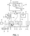
- Fig. 1 shows a schematic overview of a computing system 10 for operating a plurality of computing devices 12, 14, 16, wherein one of the computing devices 12, 14, 16 is the one computing device 12 being part of the computing system 10.
- the computing system 10 comprises beside the one of the computing devices 12 an image composing unit 18 for generating a video signal for a display device 20.
- the one computing device 12 is a master computing device 12 adapted for partitioning a display area 22 of the display device 20 in a plurality of display area sections 24, 26, 28 and relating one of the display area sections 24, 26 to the one computing device 12 and/or at least one of the display area sections 28 to another computing device 14 communicatively connectable to the computing system 10.
- the one computing device 12 is further adapted for receiving an input signal (arrow 30) from at least one (physical) input device 32, 34, 36, wherein the input signal (arrow 30) is relatable to a position 38 within the display area 22.
- the one computing device 12 is further adapted for providing the other computing device 14, 16 with the input signals (virtual input signals: arrows 40) depending on the position 38 being located in one of the display area sections 24, 26, 28 allocated to the corresponding further computing devices 14, 16.
- the display area sections 24, 26, 28 may have any type of shape, not limited to rectangles as depicted in Fig.1 .
- the image composing unit 18 is an image compositing unit 42 for generating a common video signal (arrow 44) for the display device 20, which compositing unit 42 is adapted for combining image components 46, 48, 50 from the one computing device 12 and the further computing device(s) 14, 16.
- the one computing device 12 is adapted for controlling the visibility of its own at least one image component 46, 48, wherein any image component 50 contributed by the other computing device 14, 16 cannot hide this component 46, 48.
- Another computing device 14, 16 wants a new image component 50 to be displayed or moves the position of one of its existing image component 50, it will inform the one computing device 12 via a communication channel (arrow 65).
- Fig. 2 shows the image compositing unit 42, which can be perceived as a "black box” for combining image components from separate image sources 52, 54, 56 to one output signal (arrow 44) for generating a common image 58
- the compositing unit 42 is adapted for: receiving a set of source signals (arrows 60, 62, 64), wherein each source signal is related to an according image source 52, 54, 56; determining a key information 66, especially a color coded key information or chroma key information 66, from the first source signal of the first image source 52; and switching between the source signals of the different image sources 52, 54, 56 in dependence of the determined key information 66 to create the output signal.
- the compositing unit 42 comprising a key detection unit 68, especially a chroma key detection unit 68, which controls a multiplexer unit 70 to switch between the pixel stream from the one computing device 12 and the other computing device(s) 14, 16.
- a key detection unit 68 especially a chroma key detection unit 68
- the multiplexer unit 70 switches to the assigned image source 52, 54, 56. This functionality is similar to the chroma keying used in TV productions.
- Additional chroma key information might be defined which generate the weighted average of two of the channels of source signals (instead of selecting only one channel) to generate the impression of (semi-)transparency.
- the image compositing unit 42 further comprises an image compositing controller device 72 for controlling the switching of the multiplexer unit 70 in dependence of the determined key information 66 and a synchronization verification unit 74 for verifying the synchronization of the source signals (arrows 76).
- the image composing unit 18 preferably is constructed in a way that it still operates even if one or all other computing devices 14, 16 fail and only the one computing device 12 generates pixel data.
- An image scaling unit or a picture-in-picture unit might be added to any of the video inputs to allow different resolutions and timings for each input.
- the computing system 10 for operating a plurality of computing devices 12, 14, 16 according to the different embodiments opens up different advantageous options.
- the one computing device 12 defines which display area sections 24, 26, 28 of the display area 22 show the image components (screen objects) 46, 48, 50 of which device by using a defined chroma key for each other computing device 14, 16 and painting these areas on its own display with the according chroma key. Therefore the one computing device 12 is aware of the intended position of all image components on the display device 20.
- the one computing device 12 controls priority in case of overlapping image components.
- the one computing device 12 can make its own image components visible for displaying important information that must not be covered by image components from the other computing devices.
- another computing device 14, 16 wants a new image component to be displayed or moves the position of one of its existing image components, it will inform the one computing device 12 via a communication channel 65. If the desired position of the image component is approved by the one computing device, it will paint the area for that image component on its display device with the appropriate key being a chroma key to make it visible in the resulting image. If the position is not approved by the one computing device, the image component will not be visible. The one computing device 12 might inform the other computing device 14, 16 about this.
- a special case is the presence of only one other computing device (Slave system).
- the one computing device 12 might assign the majority of the display to the slave computing device and display its image components "on top", using display area sections which cover only parts of the other computing device's display device.
- the other computing device 14, 16 does not need to inform the one computing device 12 about creation or movement of its image components. Since image components from the one cover some parts of the display area section allocated to the other computing device, the one computing device 12 might make these components semi-transparent to make the user aware of the covered parts.
- the other computing device can position its image components without intervention of the one computing device.
- Input Focus Tracking By knowing component placement and the position 38 of the input device 32 being a mouse, the one computing device 12 tracks which computing device 12, 14, 16 has focus, i.e. which computing device currently "owns" the input devices 32, 34, 36. The one computing device 12 manages the change of focus in the following way:
- the current focus is visualized to the user by means of the individual computing device (system). To avoid showing active focus on more than one computing device at a time, the focus should be actively removed from the previous focus owner when transitioning to another device.
- Achieving the effect of removing the focus from another computing device 14, 16 might be done by means of a simulated mouse click on the desktop (e.g. bottom right corner) or a simulated mouse click on an invisible window in the foreground at a known position. Alternatively, a message could be sent to the other computing device, which then takes measures to remove the focus.
- the loss-of-focus might be made visible by means of making the one computing device's display devices objects semi-transparent.
- Keyboard Events Keyboard events are forwarded to that computing device which currently has the focus and are suppressed for all other computing devices.
- keyboard might also be used for overall device control functions: Special key sequences might be defined to perform switching to a One-only full screen display or reset the whole system. This removes the necessity to have other "hard-keys” like a “reset button” for these special purposes.
- the mouse pointer position preferably is synchronized across all devices to avoid jumping of the pointer when crossing display area section boundaries on the display.
- the simulated mouse input device uses absolute positioning of the pointer instead of the relative positioning of a traditional mouse to achieve this. At any time only one instance of the mouse pointer is visible on the display so there is no problem with overlapping mouse pointer bitmaps as painted by different systems, or mouse movement delay artifacts.
- Mouse click events are forwarded to the computing device that owns the image component below the current mouse pointer position.
- the computing system receives the physical touch input events, and forwards them to the computing device which owns the image component below the current touch position.
Landscapes
- Engineering & Computer Science (AREA)
- Theoretical Computer Science (AREA)
- Physics & Mathematics (AREA)
- General Physics & Mathematics (AREA)
- General Engineering & Computer Science (AREA)
- Human Computer Interaction (AREA)
- Computer Hardware Design (AREA)
- Multimedia (AREA)
- Controls And Circuits For Display Device (AREA)
- Input From Keyboards Or The Like (AREA)
- User Interface Of Digital Computer (AREA)
Claims (9)
- Computersystem (10) zum Betreiben mehrerer Computergeräte (12, 14, 16), wobei das Computersystem (10) eines der Computergeräte (12, 14, 16) und eine Bildkompositionseinheit (18) umfasst zum Erzeugen eines gemeinsamen Videosignals für ein Anzeigegerät (20), wobei das eine Computergerät (12) angepasst ist für:- aufteilen eines Anzeigebereichs (22) der Anzeigevorrichtung (20) in mehrere Anzeigebereichsabschnitte (24, 26, 28), wobei mindestens einer der Anzeigebereichsabschnitte (24, 26) mit mindestens einem in Zusammenhang steht anderes Computergerät (14);- empfangen eines Eingabesignals von mindestens einem Eingabegerät (32, 34, 36), wobei das Eingabesignal einer Position (38) innerhalb des Anzeigebereichs (22) zugeordnet werden kann; und- versorgen des mindestens einen anderen Computergeräts (14, 16) mit dem Eingangssignal abhängig von der Position (38), die sich in einem der Anzeigebereichsabschnitte (24, 26, 28) in Bezug auf das andere Computergerät (14, 16) befindet, wobei die Bildzusammensetzungseinheit (42) dazu geeignet ist, Bildkomponenten (46, 48, 50) zur Anzeige auf dem Anzeigegerät (20) zu kombinieren, wobei die Bildkomponenten (46, 48, 50) mit dem einen Computergerät verknüpft sind (12) und mindestens ein weiteres Rechengerät (14, 16); wobei das Computersystem (10) dadurch gekennzeichnet ist, dass die Bildkompositionseinheit (18) außerdem angepasst ist für:- empfangen eines Satzes von Quellsignalen, wobei jedes Quellsignal mit einem entsprechenden Rechengerät (12, 14, 16) in Zusammenhang steht;- bestimmen einer Schlüsselinformation (66) aus einem ersten Quellsignal des einen Computergeräts (12), wobei die bestimmte Schlüsselinformation (66) der Mehrzahl von Anzeigebereichsabschnitten (24, 26, 28) entspricht; und- umschalten zwischen den Quellsignalen der verschiedenen Bildquellen (52, 54, 56) in Abhängigkeit der ermittelten Schlüsselinformationen (66), um das gemeinsame Videosignal zu erzeugen; wobei die Bildzusammensetzungseinheit (42) außerdem eine Synchronisationsverifizierungseinheit (74) zum Verifizieren der Synchronisation der Quellsignale umfasst; wobei das eine Computergerät (12) außerdem dazu geeignet ist, die Sichtbarkeit seiner eigenen mindestens einen Bildkomponente (46, 48) zu steuern, wobei keine Bildkomponente (50), die sich auf ein anderes Computergerät (14, 16) bezieht, das Bild nicht verbergen kann Komponente (46, 48) des einen Rechengeräts (12).
- Computersystem nach Anspruch 1, wobei das eine Computergerät (12) zum Empfangen von Anfragen zur Anzeige der Bildkomponenten (46, 48, 50) der Computergeräte (12, 14, 16) und zur Partitionierung der Computergeräte eingerichtet ist Anzeigebereich (22) in die Anzeigebereichsabschnitte (24, 26, 28) entsprechend den Bildkomponenten (46, 48, 50).
- Computersystem nach Anspruch 1, wobei die Bildzusammensetzungseinheit (42) umfasst:- eine Schlüsselerkennungseinheit (68) zum Ermitteln der Schlüsselinformationen (66) aus dem ersten Quellsignal;- eine Multiplexereinheit (70) zum Umschalten zwischen den verschiedenen Quellsignalen, um das Videoausgangssignal zu erzeugen; und- eine Bildzusammensetzungssteuereinrichtung (72) zum Steuern der Umschaltung der Multiplexereinheit (70) in Abhängigkeit der ermittelten Schlüsselinformationen (66).
- Computersystem nach Anspruch 3, wobei die Schlüsselinformationen (66) Chroma-Key-Informationen sind und die Schlüsselerkennungseinheit (68) eine Chroma-Key-Erkennungseinheit ist.
- Computersystem nach Anspruch 3, wobei die Bildzusammensetzungssteuervorrichtung (72) die Schlüsselerkennungseinheit (68) umfasst.
- Computersystem nach Anspruch 1, wobei die Bildzusammensetzungseinheit (42) ferner eine Bildskalierungseinheit und/oder eine Bild-in-Bild-Anzeigedatenerzeugungseinheit umfasst.
- Computersystem nach Anspruch 1, wobei die Bildzusammensetzungseinheit (42) außerdem zum Synchronisieren mindestens eines der anderen Quellsignale mit dem ersten Quellsignal konfiguriert ist.
- Verfahren zum Betreiben eines Computersystems (10) zum Betreiben mehrerer Computergeräte (12, 14, 16), wobei das Computersystem (10) eines der Computergeräte (12, 14, 16) und eine Bildkomposition umfasst Einheit (18) zum Erzeugen eines gemeinsamen Videosignals für ein Anzeigegerät (20), wobei das Verfahren umfasst, dass eines der Computergeräte die folgenden Schritte durchführt:- aufteilen eines Anzeigebereichs (22) der Anzeigevorrichtung (20) in mehrere Anzeigebereichsabschnitte (24, 26, 28), wobei mindestens einer der Anzeigebereichsabschnitte (24, 26) mit mindestens einem anderen in Zusammenhang steht Computergerät (14);- empfangen eines Eingabesignals von mindestens einem Eingabegerät (32, 34, 36), wobei das Eingabesignal einer Position (38) innerhalb des Anzeigebereichs (22) zugeordnet werden kann; und- versorgen des mindestens einen anderen Computergeräts (14, 16) mit dem Eingangssignal abhängig von der Position (38), die sich in einem der Anzeigebereichsabschnitte (24, 26, 28) in Bezug auf das andere Computergerät (14, 16) befindet, wobei das Verfahren weiterhin umfasst, dass die Bildkompositionseinheit die folgenden Schritte durchführt:- kombinieren von Bildkomponenten (46, 48, 50) zur Anzeige auf dem Anzeigegerät (20), wobei die Bildkomponenten (46, 48, 50) sich auf das eine Computergerät (12) und mindestens ein anderes Computergerät beziehen (14, 16); wobei das Verfahren dadurch gekennzeichnet ist, dass die Bildkompositionseinheit (18) die folgenden Schritte ausführt:- empfangen eines Satzes von Quellsignalen, wobei jedes Quellsignal mit einem entsprechenden Rechengerät (12, 14, 16) in Zusammenhang steht;- bestimmen einer Schlüsselinformation (66) aus einem ersten Quellsignal des einen Computergeräts (12), wobei die bestimmte Schlüsselinformation (66) der Mehrzahl von Anzeigebereichsabschnitten (24, 26, 28) entspricht; und- umschalten zwischen den Quellsignalen der verschiedenen Bildquellen (52, 54, 56) in Abhängigkeit der ermittelten Schlüsselinformationen (66), um das gemeinsame Videosignal zu erzeugen; wobei die Bildzusammensetzungseinheit (42) außerdem eine Synchronisationsüberprüfungseinheit (74) umfasst, die die Synchronisation der Quellsignale überprüft; wobei die eine Rechenvorrichtung (12) die Sichtbarkeit ihrer eigenen mindestens einen Bildkomponente (46, 48) steuert, wobei jede Bildkomponente (50), die einer anderen Rechenvorrichtung (14, 16) zugeordnet ist, die Bildkomponente (46, 48) der einen Rechenvorrichtung (12) nicht verbergen kann.
- Computerprogramm zur Verwendung in einem Computersystem (10) nach Anspruch 1, das dazu ausgelegt ist, das Computersystem dazu zu veranlassen, sich gemäß Verfahrensanspruch 8 zu verhalten.
Priority Applications (1)
| Application Number | Priority Date | Filing Date | Title |
|---|---|---|---|
| EP10740320.6A EP2454647B2 (de) | 2009-07-14 | 2010-07-01 | System, verfahren und computerprogramm für den betrieb von mehreren datenverarbeitungsvorrichtungen |
Applications Claiming Priority (3)
| Application Number | Priority Date | Filing Date | Title |
|---|---|---|---|
| EP09165399 | 2009-07-14 | ||
| EP10740320.6A EP2454647B2 (de) | 2009-07-14 | 2010-07-01 | System, verfahren und computerprogramm für den betrieb von mehreren datenverarbeitungsvorrichtungen |
| PCT/IB2010/053028 WO2011007288A1 (en) | 2009-07-14 | 2010-07-01 | System, method and computer program for operating a plurality of computing devices |
Publications (3)
| Publication Number | Publication Date |
|---|---|
| EP2454647A1 EP2454647A1 (de) | 2012-05-23 |
| EP2454647B1 EP2454647B1 (de) | 2018-09-26 |
| EP2454647B2 true EP2454647B2 (de) | 2024-02-28 |
Family
ID=42989472
Family Applications (1)
| Application Number | Title | Priority Date | Filing Date |
|---|---|---|---|
| EP10740320.6A Active EP2454647B2 (de) | 2009-07-14 | 2010-07-01 | System, verfahren und computerprogramm für den betrieb von mehreren datenverarbeitungsvorrichtungen |
Country Status (6)
| Country | Link |
|---|---|
| US (1) | US9916020B2 (de) |
| EP (1) | EP2454647B2 (de) |
| JP (1) | JP5916607B2 (de) |
| CN (1) | CN102473042B (de) |
| RU (1) | RU2566975C2 (de) |
| WO (1) | WO2011007288A1 (de) |
Families Citing this family (3)
| Publication number | Priority date | Publication date | Assignee | Title |
|---|---|---|---|---|
| JP6106983B2 (ja) * | 2011-11-30 | 2017-04-05 | 株式会社リコー | 画像表示装置、画像表示システム、方法及びプログラム |
| CN102637120B (zh) * | 2012-03-29 | 2014-11-26 | 重庆海康威视科技有限公司 | 一种控制拼接屏幕同步显示的系统及方法 |
| CN111009106B (zh) * | 2018-10-05 | 2021-11-30 | 财团法人工业技术研究院 | 人机界面系统及其通讯控制装置 |
Family Cites Families (27)
| Publication number | Priority date | Publication date | Assignee | Title |
|---|---|---|---|---|
| EP0781049B1 (de) * | 1995-12-19 | 2004-05-06 | Canon Kabushiki Kaisha | Gerät und Verfahren zur Steuerung einer Mehrzahl von Fernkameras |
| US6538675B2 (en) | 1998-04-17 | 2003-03-25 | Canon Kabushiki Kaisha | Display control apparatus and display control system for switching control of two position indication marks |
| JP3483465B2 (ja) * | 1998-04-17 | 2004-01-06 | キヤノン株式会社 | 画像表示システム |
| RU2120139C1 (ru) * | 1998-04-29 | 1998-10-10 | Айвазян Арам Оганесович | Система охраны и наблюдения |
| JPH11313339A (ja) * | 1998-04-30 | 1999-11-09 | Toshiba Corp | 表示制御装置および動画/グラフィクス合成表示方法 |
| US6249294B1 (en) | 1998-07-20 | 2001-06-19 | Hewlett-Packard Company | 3D graphics in a single logical sreen display using multiple computer systems |
| US20020030635A1 (en) * | 1998-11-16 | 2002-03-14 | Mcgowan Scott J. | Method and apparatus for phase-locking a plurality of display devices and multi-level driver for use therewith |
| JP4541476B2 (ja) | 1999-02-19 | 2010-09-08 | キヤノン株式会社 | マルチ画像表示システムおよびマルチ画像表示方法 |
| US7046229B1 (en) * | 1999-04-20 | 2006-05-16 | Microsoft Corporation | Computer input device providing absolute and relative positional information |
| GB9930306D0 (en) | 1999-12-22 | 2000-02-09 | Koninkl Philips Electronics Nv | Broadcast enhancement system and method |
| TW559699B (en) | 2000-01-12 | 2003-11-01 | Sony Corp | Image display device and method |
| JP4541482B2 (ja) * | 2000-02-29 | 2010-09-08 | キヤノン株式会社 | 画像処理装置及び画像処理方法 |
| JP2003029732A (ja) * | 2001-07-19 | 2003-01-31 | Mitsubishi Electric Corp | 画像オーバレイ装置および画像オーバレイ方法 |
| EP1423844A2 (de) * | 2001-08-27 | 2004-06-02 | Koninklijke Philips Electronics N.V. | System und verfahren zur einstellung der monitorsteuerungen in einem anzeigesystem |
| US7007236B2 (en) * | 2001-09-14 | 2006-02-28 | Accenture Global Services Gmbh | Lab window collaboration |
| US20030158886A1 (en) | 2001-10-09 | 2003-08-21 | Walls Jeffrey J. | System and method for configuring a plurality of computers that collectively render a display |
| EP1626787A4 (de) | 2003-05-23 | 2006-09-13 | Aristocrat Technologies Inc | Spielsystem mit ausgewählten synchronisierten mehrfach-videoströmen für bildschirme mit zusammengesetztem signal an der spielmaschine |
| US8639812B2 (en) | 2005-04-12 | 2014-01-28 | Belkin International, Inc. | Apparatus and system for managing multiple computers |
| JP4939811B2 (ja) | 2006-02-02 | 2012-05-30 | 三菱電機株式会社 | 画像表示装置 |
| JP2008040190A (ja) | 2006-08-08 | 2008-02-21 | Meidensha Corp | 映像切り替えシステム |
| US8244824B2 (en) | 2006-09-06 | 2012-08-14 | Stereotaxis, Inc. | Coordinated control for multiple computer-controlled medical systems |
| US20080211966A1 (en) * | 2006-09-13 | 2008-09-04 | Fujitsu Ten Limited | Image display device |
| JP2008099254A (ja) * | 2006-09-13 | 2008-04-24 | Fujitsu Ten Ltd | 映像表示装置 |
| US9024878B2 (en) | 2007-02-16 | 2015-05-05 | Emulex Corporation | Hardware cursor snooping |
| US7890570B2 (en) * | 2007-09-12 | 2011-02-15 | Citrix Systems, Inc. | Methods and systems for providing, by a remote machine, access to graphical data associated with a resource provided by a local machine |
| US8184065B2 (en) | 2007-11-12 | 2012-05-22 | Rgb Spectrum | Efficient mode switching in a video processor system |
| US8570441B2 (en) * | 2008-06-11 | 2013-10-29 | Microsoft Corporation | One pass video processing and composition for high-definition video |
-
2010
- 2010-07-01 US US13/383,725 patent/US9916020B2/en active Active
- 2010-07-01 JP JP2012520133A patent/JP5916607B2/ja active Active
- 2010-07-01 EP EP10740320.6A patent/EP2454647B2/de active Active
- 2010-07-01 RU RU2012105016/08A patent/RU2566975C2/ru not_active IP Right Cessation
- 2010-07-01 WO PCT/IB2010/053028 patent/WO2011007288A1/en not_active Ceased
- 2010-07-01 CN CN201080031568.XA patent/CN102473042B/zh active Active
Also Published As
| Publication number | Publication date |
|---|---|
| US9916020B2 (en) | 2018-03-13 |
| JP2012533786A (ja) | 2012-12-27 |
| US20120105479A1 (en) | 2012-05-03 |
| CN102473042B (zh) | 2015-04-15 |
| EP2454647B1 (de) | 2018-09-26 |
| RU2566975C2 (ru) | 2015-10-27 |
| JP5916607B2 (ja) | 2016-05-11 |
| CN102473042A (zh) | 2012-05-23 |
| WO2011007288A1 (en) | 2011-01-20 |
| EP2454647A1 (de) | 2012-05-23 |
| RU2012105016A (ru) | 2013-08-20 |
Similar Documents
| Publication | Publication Date | Title |
|---|---|---|
| AU2008318920B2 (en) | Apparatus and system for managing multiple computers | |
| US9524140B2 (en) | Apparatus and system for managing multiple computers | |
| US20140223490A1 (en) | Apparatus and method for intuitive user interaction between multiple devices | |
| EP2717140B1 (de) | Gerätesteuerungsvorrichtung, operationsempfangsverfahren und programm | |
| US8184065B2 (en) | Efficient mode switching in a video processor system | |
| JP6504256B2 (ja) | 電子黒板、電子黒板の画像処理方法、及び電子黒板のプログラムを記録した記録媒体 | |
| US20160182579A1 (en) | Method of establishing and managing messaging sessions based on user positions in a collaboration space and a collaboration system employing same | |
| US11024257B2 (en) | Android platform based display device and image display method thereof | |
| EP3610386A1 (de) | Live-tintenpräsenz für echtzeitkollaboration | |
| JP2008269615A (ja) | 複数の表示画面領域に同時にマウスポインターを表示する方法及び装置 | |
| US20160142624A1 (en) | Video device, method, and computer program product | |
| EP2454647B2 (de) | System, verfahren und computerprogramm für den betrieb von mehreren datenverarbeitungsvorrichtungen | |
| US20120242574A1 (en) | Display control device and control system | |
| WO2010144727A1 (en) | Integrated control system with multiple media sources and corresponding displays | |
| CN119883170A (zh) | 一种多屏间跨屏传送的方法、电子设备和存储介质 | |
| JP5213033B2 (ja) | ソフトウェア入力キー表示方法、プログラム及び情報処理端末 | |
| CN220367589U (zh) | 可标示主控画面的多计算机切换装置 | |
| JP2020052680A (ja) | 操作入力制御装置 | |
| JP5511023B2 (ja) | 映像表示システム及び方法 | |
| JP6186710B2 (ja) | 会議システム、及び会議方法 | |
| CN119946349A (zh) | 控制方法、第一设备及第二设备 |
Legal Events
| Date | Code | Title | Description |
|---|---|---|---|
| PUAI | Public reference made under article 153(3) epc to a published international application that has entered the european phase |
Free format text: ORIGINAL CODE: 0009012 |
|
| 17P | Request for examination filed |
Effective date: 20120214 |
|
| AK | Designated contracting states |
Kind code of ref document: A1 Designated state(s): AL AT BE BG CH CY CZ DE DK EE ES FI FR GB GR HR HU IE IS IT LI LT LU LV MC MK MT NL NO PL PT RO SE SI SK SM TR |
|
| DAX | Request for extension of the european patent (deleted) | ||
| RAP1 | Party data changed (applicant data changed or rights of an application transferred) |
Owner name: PHILIPS INTELLECTUAL PROPERTY & STANDARDS GMBH Owner name: KONINKLIJKE PHILIPS N.V. |
|
| STAA | Information on the status of an ep patent application or granted ep patent |
Free format text: STATUS: EXAMINATION IS IN PROGRESS |
|
| 17Q | First examination report despatched |
Effective date: 20170614 |
|
| GRAP | Despatch of communication of intention to grant a patent |
Free format text: ORIGINAL CODE: EPIDOSNIGR1 |
|
| STAA | Information on the status of an ep patent application or granted ep patent |
Free format text: STATUS: GRANT OF PATENT IS INTENDED |
|
| INTG | Intention to grant announced |
Effective date: 20180420 |
|
| GRAS | Grant fee paid |
Free format text: ORIGINAL CODE: EPIDOSNIGR3 |
|
| GRAA | (expected) grant |
Free format text: ORIGINAL CODE: 0009210 |
|
| STAA | Information on the status of an ep patent application or granted ep patent |
Free format text: STATUS: THE PATENT HAS BEEN GRANTED |
|
| AK | Designated contracting states |
Kind code of ref document: B1 Designated state(s): AL AT BE BG CH CY CZ DE DK EE ES FI FR GB GR HR HU IE IS IT LI LT LU LV MC MK MT NL NO PL PT RO SE SI SK SM TR |
|
| REG | Reference to a national code |
Ref country code: GB Ref legal event code: FG4D |
|
| REG | Reference to a national code |
Ref country code: CH Ref legal event code: EP |
|
| REG | Reference to a national code |
Ref country code: AT Ref legal event code: REF Ref document number: 1046800 Country of ref document: AT Kind code of ref document: T Effective date: 20181015 |
|
| REG | Reference to a national code |
Ref country code: IE Ref legal event code: FG4D |
|
| REG | Reference to a national code |
Ref country code: DE Ref legal event code: R096 Ref document number: 602010053864 Country of ref document: DE |
|
| REG | Reference to a national code |
Ref country code: NL Ref legal event code: MP Effective date: 20180926 |
|
| PG25 | Lapsed in a contracting state [announced via postgrant information from national office to epo] |
Ref country code: BG Free format text: LAPSE BECAUSE OF FAILURE TO SUBMIT A TRANSLATION OF THE DESCRIPTION OR TO PAY THE FEE WITHIN THE PRESCRIBED TIME-LIMIT Effective date: 20181226 Ref country code: SE Free format text: LAPSE BECAUSE OF FAILURE TO SUBMIT A TRANSLATION OF THE DESCRIPTION OR TO PAY THE FEE WITHIN THE PRESCRIBED TIME-LIMIT Effective date: 20180926 Ref country code: LT Free format text: LAPSE BECAUSE OF FAILURE TO SUBMIT A TRANSLATION OF THE DESCRIPTION OR TO PAY THE FEE WITHIN THE PRESCRIBED TIME-LIMIT Effective date: 20180926 Ref country code: FI Free format text: LAPSE BECAUSE OF FAILURE TO SUBMIT A TRANSLATION OF THE DESCRIPTION OR TO PAY THE FEE WITHIN THE PRESCRIBED TIME-LIMIT Effective date: 20180926 Ref country code: GR Free format text: LAPSE BECAUSE OF FAILURE TO SUBMIT A TRANSLATION OF THE DESCRIPTION OR TO PAY THE FEE WITHIN THE PRESCRIBED TIME-LIMIT Effective date: 20181227 Ref country code: NO Free format text: LAPSE BECAUSE OF FAILURE TO SUBMIT A TRANSLATION OF THE DESCRIPTION OR TO PAY THE FEE WITHIN THE PRESCRIBED TIME-LIMIT Effective date: 20181226 |
|
| REG | Reference to a national code |
Ref country code: LT Ref legal event code: MG4D |
|
| PG25 | Lapsed in a contracting state [announced via postgrant information from national office to epo] |
Ref country code: AL Free format text: LAPSE BECAUSE OF FAILURE TO SUBMIT A TRANSLATION OF THE DESCRIPTION OR TO PAY THE FEE WITHIN THE PRESCRIBED TIME-LIMIT Effective date: 20180926 Ref country code: HR Free format text: LAPSE BECAUSE OF FAILURE TO SUBMIT A TRANSLATION OF THE DESCRIPTION OR TO PAY THE FEE WITHIN THE PRESCRIBED TIME-LIMIT Effective date: 20180926 Ref country code: LV Free format text: LAPSE BECAUSE OF FAILURE TO SUBMIT A TRANSLATION OF THE DESCRIPTION OR TO PAY THE FEE WITHIN THE PRESCRIBED TIME-LIMIT Effective date: 20180926 |
|
| REG | Reference to a national code |
Ref country code: AT Ref legal event code: MK05 Ref document number: 1046800 Country of ref document: AT Kind code of ref document: T Effective date: 20180926 |
|
| PG25 | Lapsed in a contracting state [announced via postgrant information from national office to epo] |
Ref country code: EE Free format text: LAPSE BECAUSE OF FAILURE TO SUBMIT A TRANSLATION OF THE DESCRIPTION OR TO PAY THE FEE WITHIN THE PRESCRIBED TIME-LIMIT Effective date: 20180926 Ref country code: NL Free format text: LAPSE BECAUSE OF FAILURE TO SUBMIT A TRANSLATION OF THE DESCRIPTION OR TO PAY THE FEE WITHIN THE PRESCRIBED TIME-LIMIT Effective date: 20180926 Ref country code: AT Free format text: LAPSE BECAUSE OF FAILURE TO SUBMIT A TRANSLATION OF THE DESCRIPTION OR TO PAY THE FEE WITHIN THE PRESCRIBED TIME-LIMIT Effective date: 20180926 Ref country code: IT Free format text: LAPSE BECAUSE OF FAILURE TO SUBMIT A TRANSLATION OF THE DESCRIPTION OR TO PAY THE FEE WITHIN THE PRESCRIBED TIME-LIMIT Effective date: 20180926 Ref country code: CZ Free format text: LAPSE BECAUSE OF FAILURE TO SUBMIT A TRANSLATION OF THE DESCRIPTION OR TO PAY THE FEE WITHIN THE PRESCRIBED TIME-LIMIT Effective date: 20180926 Ref country code: ES Free format text: LAPSE BECAUSE OF FAILURE TO SUBMIT A TRANSLATION OF THE DESCRIPTION OR TO PAY THE FEE WITHIN THE PRESCRIBED TIME-LIMIT Effective date: 20180926 Ref country code: RO Free format text: LAPSE BECAUSE OF FAILURE TO SUBMIT A TRANSLATION OF THE DESCRIPTION OR TO PAY THE FEE WITHIN THE PRESCRIBED TIME-LIMIT Effective date: 20180926 Ref country code: IS Free format text: LAPSE BECAUSE OF FAILURE TO SUBMIT A TRANSLATION OF THE DESCRIPTION OR TO PAY THE FEE WITHIN THE PRESCRIBED TIME-LIMIT Effective date: 20190126 Ref country code: PL Free format text: LAPSE BECAUSE OF FAILURE TO SUBMIT A TRANSLATION OF THE DESCRIPTION OR TO PAY THE FEE WITHIN THE PRESCRIBED TIME-LIMIT Effective date: 20180926 |
|
| PG25 | Lapsed in a contracting state [announced via postgrant information from national office to epo] |
Ref country code: SK Free format text: LAPSE BECAUSE OF FAILURE TO SUBMIT A TRANSLATION OF THE DESCRIPTION OR TO PAY THE FEE WITHIN THE PRESCRIBED TIME-LIMIT Effective date: 20180926 Ref country code: PT Free format text: LAPSE BECAUSE OF FAILURE TO SUBMIT A TRANSLATION OF THE DESCRIPTION OR TO PAY THE FEE WITHIN THE PRESCRIBED TIME-LIMIT Effective date: 20190126 Ref country code: SM Free format text: LAPSE BECAUSE OF FAILURE TO SUBMIT A TRANSLATION OF THE DESCRIPTION OR TO PAY THE FEE WITHIN THE PRESCRIBED TIME-LIMIT Effective date: 20180926 |
|
| REG | Reference to a national code |
Ref country code: DE Ref legal event code: R026 Ref document number: 602010053864 Country of ref document: DE |
|
| PLBI | Opposition filed |
Free format text: ORIGINAL CODE: 0009260 |
|
| PLAX | Notice of opposition and request to file observation + time limit sent |
Free format text: ORIGINAL CODE: EPIDOSNOBS2 |
|
| 26 | Opposition filed |
Opponent name: MOLNIA, DAVID Effective date: 20190626 |
|
| PG25 | Lapsed in a contracting state [announced via postgrant information from national office to epo] |
Ref country code: DK Free format text: LAPSE BECAUSE OF FAILURE TO SUBMIT A TRANSLATION OF THE DESCRIPTION OR TO PAY THE FEE WITHIN THE PRESCRIBED TIME-LIMIT Effective date: 20180926 |
|
| PG25 | Lapsed in a contracting state [announced via postgrant information from national office to epo] |
Ref country code: SI Free format text: LAPSE BECAUSE OF FAILURE TO SUBMIT A TRANSLATION OF THE DESCRIPTION OR TO PAY THE FEE WITHIN THE PRESCRIBED TIME-LIMIT Effective date: 20180926 |
|
| PLBB | Reply of patent proprietor to notice(s) of opposition received |
Free format text: ORIGINAL CODE: EPIDOSNOBS3 |
|
| PG25 | Lapsed in a contracting state [announced via postgrant information from national office to epo] |
Ref country code: MC Free format text: LAPSE BECAUSE OF FAILURE TO SUBMIT A TRANSLATION OF THE DESCRIPTION OR TO PAY THE FEE WITHIN THE PRESCRIBED TIME-LIMIT Effective date: 20180926 |
|
| REG | Reference to a national code |
Ref country code: CH Ref legal event code: PL |
|
| RAP2 | Party data changed (patent owner data changed or rights of a patent transferred) |
Owner name: KONINKLIJKE PHILIPS N.V. Owner name: PHILIPS INTELLECTUAL PROPERTY & STANDARDS GMBH |
|
| GBPC | Gb: european patent ceased through non-payment of renewal fee |
Effective date: 20190701 |
|
| PG25 | Lapsed in a contracting state [announced via postgrant information from national office to epo] |
Ref country code: TR Free format text: LAPSE BECAUSE OF FAILURE TO SUBMIT A TRANSLATION OF THE DESCRIPTION OR TO PAY THE FEE WITHIN THE PRESCRIBED TIME-LIMIT Effective date: 20180926 |
|
| REG | Reference to a national code |
Ref country code: BE Ref legal event code: MM Effective date: 20190731 |
|
| PG25 | Lapsed in a contracting state [announced via postgrant information from national office to epo] |
Ref country code: GB Free format text: LAPSE BECAUSE OF NON-PAYMENT OF DUE FEES Effective date: 20190701 |
|
| PG25 | Lapsed in a contracting state [announced via postgrant information from national office to epo] |
Ref country code: CH Free format text: LAPSE BECAUSE OF NON-PAYMENT OF DUE FEES Effective date: 20190731 Ref country code: LU Free format text: LAPSE BECAUSE OF NON-PAYMENT OF DUE FEES Effective date: 20190701 Ref country code: LI Free format text: LAPSE BECAUSE OF NON-PAYMENT OF DUE FEES Effective date: 20190731 Ref country code: BE Free format text: LAPSE BECAUSE OF NON-PAYMENT OF DUE FEES Effective date: 20190731 |
|
| PG25 | Lapsed in a contracting state [announced via postgrant information from national office to epo] |
Ref country code: IE Free format text: LAPSE BECAUSE OF NON-PAYMENT OF DUE FEES Effective date: 20190701 |
|
| REG | Reference to a national code |
Ref country code: DE Ref legal event code: R081 Ref document number: 602010053864 Country of ref document: DE Owner name: PHILIPS GMBH, DE Free format text: FORMER OWNER: PHILIPS INTELLECTUAL PROPERTY & STANDARDS GMBH, 20099 HAMBURG, DE |
|
| PG25 | Lapsed in a contracting state [announced via postgrant information from national office to epo] |
Ref country code: CY Free format text: LAPSE BECAUSE OF FAILURE TO SUBMIT A TRANSLATION OF THE DESCRIPTION OR TO PAY THE FEE WITHIN THE PRESCRIBED TIME-LIMIT Effective date: 20180926 |
|
| RIC2 | Information provided on ipc code assigned after grant |
Ipc: G09G 5/14 20060101AFI20210521BHEP Ipc: G09G 5/12 20060101ALI20210521BHEP Ipc: G06F 3/038 20130101ALI20210521BHEP Ipc: G06F 3/14 20060101ALI20210521BHEP |
|
| PG25 | Lapsed in a contracting state [announced via postgrant information from national office to epo] |
Ref country code: MT Free format text: LAPSE BECAUSE OF FAILURE TO SUBMIT A TRANSLATION OF THE DESCRIPTION OR TO PAY THE FEE WITHIN THE PRESCRIBED TIME-LIMIT Effective date: 20180926 Ref country code: HU Free format text: LAPSE BECAUSE OF FAILURE TO SUBMIT A TRANSLATION OF THE DESCRIPTION OR TO PAY THE FEE WITHIN THE PRESCRIBED TIME-LIMIT; INVALID AB INITIO Effective date: 20100701 |
|
| APBM | Appeal reference recorded |
Free format text: ORIGINAL CODE: EPIDOSNREFNO |
|
| APBP | Date of receipt of notice of appeal recorded |
Free format text: ORIGINAL CODE: EPIDOSNNOA2O |
|
| APAH | Appeal reference modified |
Free format text: ORIGINAL CODE: EPIDOSCREFNO |
|
| APBQ | Date of receipt of statement of grounds of appeal recorded |
Free format text: ORIGINAL CODE: EPIDOSNNOA3O |
|
| APAH | Appeal reference modified |
Free format text: ORIGINAL CODE: EPIDOSCREFNO |
|
| PG25 | Lapsed in a contracting state [announced via postgrant information from national office to epo] |
Ref country code: MK Free format text: LAPSE BECAUSE OF FAILURE TO SUBMIT A TRANSLATION OF THE DESCRIPTION OR TO PAY THE FEE WITHIN THE PRESCRIBED TIME-LIMIT Effective date: 20180926 |
|
| APBU | Appeal procedure closed |
Free format text: ORIGINAL CODE: EPIDOSNNOA9O |
|
| REG | Reference to a national code |
Ref country code: CH Ref legal event code: PK Free format text: BERICHTIGUNGEN |
|
| RIN2 | Information on inventor provided after grant (corrected) |
Inventor name: BECK, ROLAND, CLAUS Inventor name: LUDWIG, ALF |
|
| PUAH | Patent maintained in amended form |
Free format text: ORIGINAL CODE: 0009272 |
|
| STAA | Information on the status of an ep patent application or granted ep patent |
Free format text: STATUS: PATENT MAINTAINED AS AMENDED |
|
| 27A | Patent maintained in amended form |
Effective date: 20240228 |
|
| AK | Designated contracting states |
Kind code of ref document: B2 Designated state(s): AL AT BE BG CH CY CZ DE DK EE ES FI FR GB GR HR HU IE IS IT LI LT LU LV MC MK MT NL NO PL PT RO SE SI SK SM TR |
|
| REG | Reference to a national code |
Ref country code: DE Ref legal event code: R102 Ref document number: 602010053864 Country of ref document: DE |
|
| PGFP | Annual fee paid to national office [announced via postgrant information from national office to epo] |
Ref country code: DE Payment date: 20250728 Year of fee payment: 16 |
|
| PGFP | Annual fee paid to national office [announced via postgrant information from national office to epo] |
Ref country code: FR Payment date: 20250725 Year of fee payment: 16 |