EP2453984B1 - Bestrahlung bzw. bestrahlungsplanung für ein rescanning-verfahren mit einem partikelstrahl - Google Patents
Bestrahlung bzw. bestrahlungsplanung für ein rescanning-verfahren mit einem partikelstrahl Download PDFInfo
- Publication number
- EP2453984B1 EP2453984B1 EP10730121.0A EP10730121A EP2453984B1 EP 2453984 B1 EP2453984 B1 EP 2453984B1 EP 10730121 A EP10730121 A EP 10730121A EP 2453984 B1 EP2453984 B1 EP 2453984B1
- Authority
- EP
- European Patent Office
- Prior art keywords
- target
- rescanning
- targeted
- pass
- target point
- Prior art date
- Legal status (The legal status is an assumption and is not a legal conclusion. Google has not performed a legal analysis and makes no representation as to the accuracy of the status listed.)
- Not-in-force
Links
Images

Classifications
-
- A—HUMAN NECESSITIES
- A61—MEDICAL OR VETERINARY SCIENCE; HYGIENE
- A61N—ELECTROTHERAPY; MAGNETOTHERAPY; RADIATION THERAPY; ULTRASOUND THERAPY
- A61N5/00—Radiation therapy
- A61N5/10—X-ray therapy; Gamma-ray therapy; Particle-irradiation therapy
- A61N5/103—Treatment planning systems
-
- A—HUMAN NECESSITIES
- A61—MEDICAL OR VETERINARY SCIENCE; HYGIENE
- A61N—ELECTROTHERAPY; MAGNETOTHERAPY; RADIATION THERAPY; ULTRASOUND THERAPY
- A61N5/00—Radiation therapy
- A61N5/10—X-ray therapy; Gamma-ray therapy; Particle-irradiation therapy
- A61N5/103—Treatment planning systems
- A61N5/1031—Treatment planning systems using a specific method of dose optimization
-
- A—HUMAN NECESSITIES
- A61—MEDICAL OR VETERINARY SCIENCE; HYGIENE
- A61N—ELECTROTHERAPY; MAGNETOTHERAPY; RADIATION THERAPY; ULTRASOUND THERAPY
- A61N5/00—Radiation therapy
- A61N5/10—X-ray therapy; Gamma-ray therapy; Particle-irradiation therapy
- A61N5/1042—X-ray therapy; Gamma-ray therapy; Particle-irradiation therapy with spatial modulation of the radiation beam within the treatment head
- A61N5/1043—Scanning the radiation beam, e.g. spot scanning or raster scanning
- A61N5/1044—Scanning the radiation beam, e.g. spot scanning or raster scanning with multiple repetitions of the scanning pattern
-
- A—HUMAN NECESSITIES
- A61—MEDICAL OR VETERINARY SCIENCE; HYGIENE
- A61N—ELECTROTHERAPY; MAGNETOTHERAPY; RADIATION THERAPY; ULTRASOUND THERAPY
- A61N5/00—Radiation therapy
- A61N5/10—X-ray therapy; Gamma-ray therapy; Particle-irradiation therapy
- A61N2005/1085—X-ray therapy; Gamma-ray therapy; Particle-irradiation therapy characterised by the type of particles applied to the patient
- A61N2005/1087—Ions; Protons
Definitions
- the invention relates to a method for irradiation planning of a target volume, a method for irradiating a target area in a target volume, an irradiation planning device, a control device for an irradiation system and an irradiation system with such a control device, which implement or enable a rescanning irradiation method.
- Such an irradiation method is used in particular for the irradiation of moving target volumes for the compensation of the irradiation inaccuracies caused by the movement of the target volume.
- Particle therapy is an established method for the treatment of tissue, in particular tumor diseases. Irradiation methods, such as those used in particle therapy, are also used in non-therapeutic areas.
- irradiation of materials include, for example, research work, for example on product development, in the context of particle therapy, which are performed on non-living phantoms or bodies, irradiation of materials, etc.
- charged particles such as protons or carbon ions or other ions are accelerated to high energies, formed into a particle beam and passed through a high-energy beam transport system to one or more irradiation rooms.
- the target volume to be irradiated is irradiated with the particle beam. It may happen that the target volume to be irradiated moves.
- a movement of the tumor to be irradiated may be caused by a respiratory movement.
- Such a movement can also be modeled on model objects known as phantoms for research purposes.
- the target volume to be irradiated is usually divided into a plurality of target areas.
- the target areas are irradiated in the rescanning process, ie each with multiple Rescan passes.
- the target areas are usually scanned successively, ie, as soon as a target area has been scanned in the rescanning method, the next target area is again scanned in the rescanning method, etc.
- the dose distribution that is set for the target area may be inhomogeneous. Even if the total dose to be applied for the target volume has a homogeneous dose distribution, it may be necessary for the dose distribution to be administered to be inhomogeneous for a target area. This is because parts of the target area have already been pre-dosed during irradiation of other target areas.
- the dose distribution can represent a measure of the number of particles to be applied.
- the dose distribution can be determined in a planning phase taking account of planning specifications with regard to target volume, the dose to be deposited in the target volume and / or the effective effect of the dose deposited in the tissue - for example charac- terizable by the indication of the relative biological efficacy (RBW or RBE).
- the dose distribution for the target area is applied in that the target points of the target area are approached different times during the rescan passages.
- approximately a target point is meant that in the target point a single dose is applied or that this is planned.
- an inhomogeneous dose distribution can be easily applied in this way.
- a target point for which a higher total dose is provided can be approached more often during the rescan passages than a target point for which a lower total dose is provided.
- the target points of the target area are approached differently often, it follows that at least a part the target points are not approached during certain Rescan passes. If, for example, a total of 10 rescan passes are provided, but a target point is to be approached only seven times in total, there are 3 rescan passes in which the target point is not approached, ie is skipped.
- the invention is based on the idea that it is advantageous if the approach of the target points is distributed to the rescan passes in such a way that at least one target point, which is not approached in each rescan pass, before the last rescan pass, in which this target point is approached, at least one further Rescan-passage is in which this target point is not approached.
- This can be achieved, for example, by not approaching this target point on the first rescan pass.
- this can also be achieved by at least one further rescan pass lies at a target point, which is approached in at least two Rescan passes, between these two Rescan passes, in which the target point is not approached.
- This rigid scheme has broken through the present planning process. This makes it possible to reduce the irradiation of a target point to a later time, i. to move to a later rescan run. This makes it possible to reduce or avoid the described negative effects.
- a target point that is approached only on a later rescan pass can be used to connect the remaining islands of the later rescan pass.
- the beam path that is traversed during the later rescan pass can be flexibly optimized. Even if usually several target points are used to connect the remaining islands of a later rescan pass, depending on the constellation of the geometry of the target area and the dose distribution to be applied, a single target point can be approached only during a later rescan pass , lead to improved execution of the rescan passes.
- the target points to be approached during the rescan passes can also be divided in such a way that many target points per rescan pass are approached as uniformly as possible, ie, the number of target points approached on each pass is essentially the same.
- This substantially uniform distribution causes "thinning out” does not occur or only to a very limited extent. This can be achieved, for example, by the fact that with each rescan pass one or more target points exist that are not approached.
- the target points and the number The approaches per destination can be statistically distributed via the rescan passes.
- One way of performing the splitting of the target points on the rescan passes is to perform the splitting with respect to the scan path, such that a scan path is used to approach the target points to be approached in one of the rescan passes , meets a predefined criterion. For example, after splitting the target points, it can be checked whether the resulting scan path fulfills the predefined criteria for each rescan run. If this is not the case, the splitting of the target points can be changed.
- the splitting can also be designed a priori so that certain combinations of target points and rescan passes are not allowed or punished in the algorithm to be performed.
- the predefined criterion may be, for example, that in a scan path a distance between two target points to be approached in succession is below a threshold. For example, it can be determined that the maximum distance between two target points is less than 20 mm, in particular less than 10 mm or 5 mm. In this case, namely, the scanning can be done without a shutdown of the beam between the two target points is mandatory.
- Other possible criteria can be: The number of necessary interruptions of the beam when scanning the scan path, which should be minimized or which should be below a threshold value.
- the planning method is designed such that at a target point the total dose to be administered is an integer multiple of the single dose to be applied at this target point, which is always applied when the target point is approached in a rescan run.
- This restriction has the advantage that the entire single dose can always be administered in each target point. The application of fractions The single dose, which is sometimes problematic because it may not be monitored with the required accuracy, is thereby avoided.
- This embodiment variant can also be implemented independently of the disclosed method. This means that in rescanning or in a radiation planning for a rescanning procedure per target point only ratios between total dose and single dose are allowed, which are integer. In this way it can be ensured that the entire single dose is always administered per target point.
- Such a design can be implemented, for example. by specifying boundary conditions which limit the freedom in the determination of the irradiation parameters. For example, the spatial position of the target points can be chosen so that this requirement can be met.
- the single dose which is based on the integer ratio, can be chosen to be the same for the entire treatment plan, or different for different sections of the treatment plan - as for different target areas.
- the single dose can also be advantageous to select the single dose to be applied in a target point, ie the dose that is applied when the target point approaches, in particular during rescanning, so that the single dose always lies above a predetermined threshold value.
- the single dose may be tailored to the choice of measuring range of the measuring instruments and to the extracted intensity from the accelerator; Overall, the possibilities of the hardware used are explicitly taken into account. If, in the course of irradiation, the hardware is operated in a different operating mode, eg with a changed extracted intensity and / or with a different choice of the measuring range of the detectors, the predetermined threshold value can be adapted.
- the single dose should be chosen as small as possible within this specification, since then the number of rescan passages is increased and thus the positive effects of rescanning become more pronounced.
- the prescription "total dose is an integer multiple of the single dose" can be fulfilled more easily.
- the single dose may always be below ten times or five times the threshold, in particular below twice the threshold. Irradiation planning devices or control devices for irradiation facilities can be designed accordingly.
- an equally large single dose is always applied at the target points of the target area.
- This embodiment variant is particularly suitable for being installed on an irradiation facility because an irradiation facility can be designed and optimized for the same single dose to be administered.
- the measuring ranges of the devices with which the administration of the single dose is monitored can be adapted to the size of the single dose.
- irradiation may occur without switching isoenergy layers and / or without switching over the intensity with which the particle beam is extracted by the accelerator unit and / or without switching over the measuring ranges of the measuring devices such as the ionization chamber system, resulting in an equal single dose.
- the method according to the invention for irradiating a target area in a target volume is designed in such a way that the target area comprises target points to be approached individually and that in particular an inhomogeneous dose distribution is applied in the target area.
- the target area is irradiated with a multitude of rescan passes, ie the target area is thus scanned several times in total.
- the target points of the target area itself are approached a different number of times during the rescan passes, so that at least part of the target points are not approached with each rescan pass.
- the method is designed such that at least one target point that is not approached in each rescan pass before the last rescan pass, in which this target point is approached, at least one further Rescan-passage is performed, in which this target point is not approached.
- the irradiation planning device has a computer unit which is designed to carry out one of the disclosed methods for irradiation planning. This can be done, for example, by using a suitable computer program.
- the irradiation facility control apparatus includes a control computer that controls an irradiation facility during irradiation to perform one of the disclosed methods for irradiating a target area in a target volume. This can also be done with a suitable computer program.
- the irradiation system according to the invention has such a control device.
- Embodiments and advantages that have been listed and explained for the method for irradiation planning also apply to the method for irradiating a target area in a target volume, and in the same way for the irradiation planning device and for the control device for an irradiation facility.
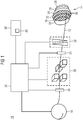
- Fig. 1 shows a highly schematic representation of a structure of a particle therapy system 10.
- the particle therapy system 10 is used for irradiating a arranged on a positioning body with a beam of particles, which is referred to below as the particle beam 12.
- a tumor-damaged tissue of a patient can be irradiated with the particle beam 12 as target volume 14.
- the particle beam system 10 for irradiating a non-living body, in particular a water phantom or another phantom.
- the irradiation of the water phantom can be carried out, for example, for purposes of checking and verifying irradiation parameters before and / or after irradiation of a patient.
- the particle therapy system 10 typically has an accelerator unit 16, for example a synchrotron, a cyclotron or another accelerator, which provides a particle beam 12 with the energy required for the irradiation.
- an accelerator unit 16 for example a synchrotron, a cyclotron or another accelerator, which provides a particle beam 12 with the energy required for the irradiation.
- particles are mainly particles such as protons, pions, helium ions, carbon ions or ions of other elements used.
- a particle beam 12 has a beam diameter of 3-10 mm.
- Layers 18, 20, 22, 24, 26 and 28, which correspond to isoenergy layers, are indicated in the target volume 14 to be irradiated.
- An isoenergy layer 18, 20, 22, 24, 26 or 28 is characterized by the penetration depth of the particle beam 12 at a certain energy of the particle beam 12.
- Each isoenergy layer 18, 20, 22, 24, 26, 28 in the example shown here represents a target area within the target volume 14 which is to be irradiated in the rescanning method.
- a raster scan method is preferably used, in which a particle beam 12 is guided from target point 50 to target point 50 without inevitable shutdown during a transition from one target point 50 to the next. It is also possible to use spot scanning methods with the particle beam being switched off between the individual target points 50 or other scanning methods, such as, for example, continuous scanning methods, in order to irradiate the target area with a rescanning method.
- spot scanning methods with the particle beam being switched off between the individual target points 50 or other scanning methods, such as, for example, continuous scanning methods, in order to irradiate the target area with a rescanning method.
- Fig. 1 some target points 50 of the central isoenergy layer 22 are shown in the target volume 14, which are approached successively with the particle beam 12.
- the particle beam 12 is influenced in its lateral deflection by means of scan magnets 30, ie deflected in its position perpendicular to the beam path direction, also referred to as the x and y direction. Furthermore, an energy modulation device 32 can be provided, with which the energy of the particle beam 12 can be changed quickly, so that the penetration depth of the particle beam 12 can be varied. In this way, a rescanning in the beam direction of the particle beam 12 is possible ("volumetric rescanning", ie the beam path does not have to run within an isoenergy layer).
- the irradiation system 10 also has a sequence controller 36 and detectors 34 for monitoring the beam parameters.
- the arrangement of the components of the particle beam system 10 shown here is merely an example. Also, structures of another arrangement are conceivable.
- the sequence control 36 ie the control system of the system, controls the individual components of the system, such as the accelerator 16, the scan magnets 30 and collects measurement data such as the data of the detectors 34 for monitoring the beam parameters.
- the control is based on an irradiation plan 40, which is determined and provided by means of an irradiation planning device 38.
- the target volume 14 in Fig. 1 has an ellipsoidal shape. If the target volume 14 is to be irradiated overall with a homogeneous nominal dose, this means for the central isoenergy layer 22 that the dose distribution to be applied in the central isoenergy layer 22 is inhomogeneous. This is due to the fact that the central area of the middle isoenergy layer 22 is already loaded by a small dose when the isoenergy layers 24, 26, 28 lying in the beam direction behind the central isoenergy layer 22 are irradiated. For the middle isoenergy layer 22, the dose to be applied is therefore greater at the edge than at the center.
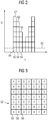
- the dose distribution to be applied to the middle isoenergy layer 22 is for some target points of the middle isoenergy layer in FIG Fig. 2 shown.
- the x-axis indicates the location x of the target points along a line within the middle isoenergy layer, the y-axis the total dose D.
- Dashed lines indicate a threshold value 60, which specifies the minimum fluence-and hereby also specifies the minimum dose to be administered-the application of which can be monitored by the measuring instruments of the particle therapy system 10 with the required accuracy.
- the total inhomogeneous dose 62 to be applied for the middle isoenergy layer 22 is chosen such that the total dose 62 to be applied in the target points 50 is always an integer multiple of a single dose 64. This choice is generally made during the treatment planning and is therefore generally possible without problems, since the single dose 64 is chosen to be so small that it is just above the threshold value 60, that is usually significantly smaller than the total dose 62 to be applied.
- the single dose 64 may be e.g. are below 1.5 times the threshold value 60.
- the choice of the single dose 64 ensures that on the one hand it is ensured that the dose application can be monitored with due accuracy, and that on the other hand as many Rescan passes can be driven to apply the total dose 62 for the middle Isoenergy Mrs 22.
- the isoenergy layer is irradiated by the rescanning method.
- a target point 50 is approached as often as possible during the various rescan passes until the total dose 62 for this target point 50 has been reached.
- the entire single dose 64 can be applied on the basis of the integer ratio.
- Prescribing the single dose causes proximal layers, which are generally irradiated at a lower dose, as these layers are pre-dosed, to be irradiated with fewer rescans.
- proximal layers which are generally irradiated at a lower dose, as these layers are pre-dosed, to be irradiated with fewer rescans.
- this is justifiable since these areas are already covered by the irradiation of distal layers has already been irradiated indirectly in multiple rescan passages.
- settings are generally used in proximal layers, which allow a more accurate dose measurement and therefore smaller threshold values 60. This can be achieved, for example, via a lower intensity of the particle beam and through the choice of a more sensitive measuring range of the measuring devices, such as ionization chambers, with which the dose application of the particle beam is monitored.
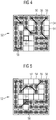
- FIG. 3 to 8 An embodiment of the method according to the invention will be explained with reference to the representation of a fictitious, square isoenergy layer 52.
- the illustrated isoenergy layer 52 is a great simplification of an isoenergy layer which normally occurs in reality. However, the basic principle can be better explained.
- Fig. 3 shows for each target point 50 the total dose to be administered as a multiple of a single dose. It can be seen that the total dose in the peripheral regions of the isoenergy square 52 is greater (ie up to a 4-fold of the single dose) than in the center (only 1-fold of the single dose). This corresponds roughly to the basic principle in Fig. 2 shown inhomogeneous dose distribution.
- Fig. 4 to Fig. 7 shows the approach of the target points for four successive Rescan passes.
- An occupied box 56 means that the target point is approached during the corresponding rescan pass and that the single dose is administered at the target point, whereas an unassigned box 54 means that the target point was not approached during the rescan pass, ie omitted, becomes.
- the target points 50 were distributed to the rescan passages in such a way that a constant number of target points 50 is reached at each rescan pass. Furthermore, in the distribution of the start of the Target points 50 on the Rescan passages ensured that always a continuous scan path 58 can be found so that irradiation in a Rescan passage is possible without interruption.
- the division causes some target points to be approached only in later rescan passes. This makes it possible to find cheap scan paths 58.
- As methods for this known algorithms as they are used in general Traveling-Salesman problems can be used. Especially in the case of complex target areas, as they occur in reality, it may otherwise be the case that non-contiguous islands from target points would have to be approached in a rescan pass. This can be prevented by the described division of the approach of the target points 50 to different Rescan passes.
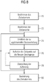
- Fig. 8 shows a schematic representation of the process steps, which are carried out in the planning of irradiation in the rescanning process.
- a target volume is defined in the object to be irradiated (step 70). Subsequently, the target volume is divided into target areas, which are each to be irradiated in several rescan passes (step 72).
- the dose distribution to be applied is determined (step 74).
- This can be a single dose determined, which describes the dose that is delivered in a target point per approach of the target point.
- this single dose can also be determined, for example, from the outset.
- the determination of the dose distribution to be applied can also be carried out under certain boundary conditions, for example it can be stipulated that the total dose to be administered per target point is an integer multiple of a single dose. From the single dose and from the total dose per target point, the number of rescan passes, which must be applied in order to apply the desired dose distribution in the target area.
- the target points or the approach of the target points are distributed to the rescan passes, in such a way that at least one target point, which is not approached with each rescan pass, at least one rescan pass before the last approach of the target point, during which this target point is not approached (step 76).
- step 78 After the approach of the target points has been split up to the rescan passes, it is checked whether the target points can be approached with a scan path that meets predefined criteria at each rescan pass (step 78). For example, it can be checked whether the number of interruptions of the beam, which are necessary in the execution of a scan path, are below a value or are minimized.
- the distribution of the target points or the approach of the target points can be changed in such a way that the resulting scan paths better fulfill the predefined criteria.
- the division of the target points into rescan passes is repeated for each target area in a similar manner. Subsequently, the irradiation of the target volume or the target areas of the target volume according to the irradiation planning (step 80).
- the method can be combined with other methods relating to rescanning.
- the rescan passes may be timed such that desynchronization occurs with the movement of the target volume, it may be performed by a method such as that described in U.S. Pat US 20080078942 A1
- the embodiments which do not fall within the scope of the appended claims are for illustrative purposes only and are not subject of the present invention.
- the invention is defined by the following claims.
Landscapes
- Health & Medical Sciences (AREA)
- Engineering & Computer Science (AREA)
- Biomedical Technology (AREA)
- Pathology (AREA)
- Nuclear Medicine, Radiotherapy & Molecular Imaging (AREA)
- Radiology & Medical Imaging (AREA)
- Life Sciences & Earth Sciences (AREA)
- Animal Behavior & Ethology (AREA)
- General Health & Medical Sciences (AREA)
- Public Health (AREA)
- Veterinary Medicine (AREA)
- Radiation-Therapy Devices (AREA)
Applications Claiming Priority (2)
| Application Number | Priority Date | Filing Date | Title |
|---|---|---|---|
| DE102009033297A DE102009033297A1 (de) | 2009-07-15 | 2009-07-15 | Bestrahlung bzw. Bestrahlungsplanung für ein Rescanning-Verfahren mit einem Partikelstrahl |
| PCT/EP2010/058636 WO2011006733A1 (de) | 2009-07-15 | 2010-06-18 | Bestrahlung bzw. bestrahlungsplanung für ein rescanning-verfahren mit einem partikelstrahl |
Publications (2)
| Publication Number | Publication Date |
|---|---|
| EP2453984A1 EP2453984A1 (de) | 2012-05-23 |
| EP2453984B1 true EP2453984B1 (de) | 2018-01-03 |
Family
ID=42671885
Family Applications (1)
| Application Number | Title | Priority Date | Filing Date |
|---|---|---|---|
| EP10730121.0A Not-in-force EP2453984B1 (de) | 2009-07-15 | 2010-06-18 | Bestrahlung bzw. bestrahlungsplanung für ein rescanning-verfahren mit einem partikelstrahl |
Country Status (6)
| Country | Link |
|---|---|
| US (1) | US8809814B2 (enExample) |
| EP (1) | EP2453984B1 (enExample) |
| JP (1) | JP6105285B2 (enExample) |
| CN (1) | CN102548613B (enExample) |
| DE (1) | DE102009033297A1 (enExample) |
| WO (1) | WO2011006733A1 (enExample) |
Families Citing this family (22)
| Publication number | Priority date | Publication date | Assignee | Title |
|---|---|---|---|---|
| DE102008048916A1 (de) * | 2008-09-26 | 2010-04-29 | Gsi Helmholtzzentrum Für Schwerionenforschung Gmbh | Schnelles Scanning eines Zielgebiets |
| DE102008051476A1 (de) * | 2008-10-13 | 2010-04-29 | Gsi Helmholtzzentrum Für Schwerionenforschung Gmbh | Vorrichtung und Verfahren zur Bestimmung von Steuerparametern für eine Bestrahlungsanlage, Bestrahlungsanlage und Bestrahlungsverfahren |
| DE102011018613B4 (de) * | 2011-04-21 | 2016-05-12 | Gsi Helmholtzzentrum Für Schwerionenforschung Gmbh | Bestrahlungsanlage mit mehreren einstellbaren Messbereichen einer Strahlmonitoreinrichtung und Steuerverfahren für diese Bestrahlungsanlage |
| DE102012004170B4 (de) * | 2012-03-05 | 2013-11-07 | Gsi Helmholtzzentrum Für Schwerionenforschung Gmbh | Verfahren und Bestrahlungsanlage zur Bestrahlung eines Zielvolumens |
| WO2013171820A1 (ja) * | 2012-05-14 | 2013-11-21 | 三菱電機株式会社 | 粒子線スキャニング照射システム |
| DE102012212341B3 (de) * | 2012-07-13 | 2013-11-28 | Siemens Aktiengesellschaft | Bestimmen eines zeitoptimierten Bestrahlungsplans für eine Partikelbestrahlungsanlage unter Vorgabe einer Randbedingung |
| DE102012212340B3 (de) | 2012-07-13 | 2013-11-28 | Siemens Aktiengesellschaft | Bestimmen eines zeitoptimierten Bestrahlungsplans für eine Partikelbestrahlungsanlage |
| DE102012220465A1 (de) * | 2012-11-09 | 2014-05-15 | Carl Zeiss Smt Gmbh | EUV-Kollektor |
| DE102012110864B4 (de) * | 2012-11-12 | 2014-08-21 | Gsi Helmholtzzentrum Für Schwerionenforschung Gmbh | Bewegungsrobuste Bestrahlungsplanung mittels Teilbestrahlungsplänen |
| CN104797294B (zh) | 2012-11-20 | 2017-06-13 | 三菱电机株式会社 | 治疗计划装置、粒子射线治疗装置以及带电粒子射束的扫描路径决定方法 |
| EP3093045A4 (en) * | 2014-01-10 | 2017-11-01 | Mitsubishi Electric Corporation | Particle beam irradiation apparatus |
| CN106163616B (zh) * | 2014-04-10 | 2019-02-26 | 株式会社日立制作所 | 粒子射线照射装置 |
| CN104933131B (zh) * | 2015-06-12 | 2017-09-15 | 北京海泰方圆科技股份有限公司 | 一种动态调整电子文件遍历频率的方法 |
| JP6634299B2 (ja) * | 2016-01-28 | 2020-01-22 | 株式会社日立製作所 | 治療計画装置、治療計画方法、制御装置および粒子線治療システム |
| JP6139717B2 (ja) * | 2016-02-01 | 2017-05-31 | 三菱電機株式会社 | 治療計画装置、粒子線治療装置、および荷電粒子ビームの走査経路の決定方法 |
| CN108697904A (zh) * | 2016-02-15 | 2018-10-23 | 三菱电机株式会社 | 粒子射线治疗装置及粒子射线治疗装置的扫描次数决定方法 |
| CN106730407A (zh) * | 2016-11-18 | 2017-05-31 | 上海艾普强粒子设备有限公司 | 一种用于粒子治疗的扫描照射方法、装置和治疗头 |
| JP6328279B2 (ja) * | 2017-01-18 | 2018-05-23 | 三菱電機株式会社 | 治療計画装置、粒子線治療装置、および荷電粒子ビームの走査経路の決定方法 |
| JP6839987B2 (ja) * | 2017-01-19 | 2021-03-10 | 株式会社日立製作所 | 治療計画装置および粒子線治療システム |
| EP3618924A1 (en) * | 2017-05-03 | 2020-03-11 | RaySearch Laboratories AB | System and method for ion based radiotherapy treatment planning |
| EP3421085A1 (en) * | 2017-06-28 | 2019-01-02 | RaySearch Laboratories AB | Determining a distribution of spots of varying sizes for ion beam therapy using optimization |
| CN115120892B (zh) * | 2022-08-25 | 2022-11-22 | 合肥中科离子医学技术装备有限公司 | 打火保护方法、控制装置、医用回旋加速器和存储介质 |
Family Cites Families (8)
| Publication number | Priority date | Publication date | Assignee | Title |
|---|---|---|---|---|
| JP4282198B2 (ja) * | 2000-02-03 | 2009-06-17 | 株式会社東芝 | 粒子線照射装置 |
| US6757355B1 (en) * | 2000-08-17 | 2004-06-29 | Siemens Medical Solutions Usa, Inc. | High definition radiation treatment with an intensity modulating multi-leaf collimator |
| US7525104B2 (en) * | 2005-02-04 | 2009-04-28 | Mitsubishi Denki Kabushiki Kaisha | Particle beam irradiation method and particle beam irradiation apparatus used for the same |
| DE102005063220A1 (de) | 2005-12-22 | 2007-06-28 | GSI Gesellschaft für Schwerionenforschung mbH | Vorrichtung zum Bestrahlen von Tumorgewebe eines Patienten mit einem Teilchenstrahl |
| DE102006046193B3 (de) | 2006-09-29 | 2008-05-08 | Siemens Ag | Partikeltherapieanlage für die Partikeltherapie eines einer Bewegung ausgesetzten Zielvolumens |
| JP4655062B2 (ja) * | 2007-05-09 | 2011-03-23 | 株式会社日立製作所 | 粒子線治療システムの照射装置 |
| DE102007045879B4 (de) | 2007-09-25 | 2014-07-10 | Gsi Helmholtzzentrum Für Schwerionenforschung Gmbh | Bestrahlung eines bewegten Zielvolumens |
| DE102008027485B4 (de) * | 2008-06-09 | 2010-02-11 | Gsi Helmholtzzentrum Für Schwerionenforschung Gmbh | Deposition einer Solldosisverteilung in einem zyklisch bewegten Zielgebiet |
-
2009
- 2009-07-15 DE DE102009033297A patent/DE102009033297A1/de not_active Ceased
-
2010
- 2010-06-18 CN CN201080036718.6A patent/CN102548613B/zh not_active Expired - Fee Related
- 2010-06-18 WO PCT/EP2010/058636 patent/WO2011006733A1/de not_active Ceased
- 2010-06-18 US US13/384,232 patent/US8809814B2/en active Active
- 2010-06-18 JP JP2012519954A patent/JP6105285B2/ja not_active Expired - Fee Related
- 2010-06-18 EP EP10730121.0A patent/EP2453984B1/de not_active Not-in-force
Also Published As
| Publication number | Publication date |
|---|---|
| DE102009033297A1 (de) | 2011-01-20 |
| EP2453984A1 (de) | 2012-05-23 |
| CN102548613A (zh) | 2012-07-04 |
| WO2011006733A1 (de) | 2011-01-20 |
| JP6105285B2 (ja) | 2017-03-29 |
| JP2012532712A (ja) | 2012-12-20 |
| US20120187314A1 (en) | 2012-07-26 |
| US8809814B2 (en) | 2014-08-19 |
| CN102548613B (zh) | 2014-10-15 |
Similar Documents
| Publication | Publication Date | Title |
|---|---|---|
| EP2453984B1 (de) | Bestrahlung bzw. bestrahlungsplanung für ein rescanning-verfahren mit einem partikelstrahl | |
| EP2352556B1 (de) | Bestrahlung von zumindest zwei zielvolumen | |
| EP2108402B1 (de) | Verfahren und Vorrichtung zum Erstellen eines Bestrahlungsplans | |
| DE102008009765B4 (de) | Bestimmen von Steuerparametern einer Bestrahlungsanlage für eine Bestrahlung eines Zielvolumens | |
| DE102008010958B4 (de) | Konformales Mehrschicht-Strahlentherapiesystem und dieses verwendende Teilchenstrahl-Therapievorrichtung | |
| DE102007014715B4 (de) | Bestimmung von Steuerparametern für eine Bestrahlung eines bewegten Zielvolumens in einem Körper | |
| EP2177244B1 (de) | Anlage zur Bestrahlung von Patienten mit geladenen Teilchen und Verfahren zur Überwachung der Anlage | |
| DE102011088160B3 (de) | Bestrahlungsplanungverfahren und Bestrahlungsplanungsvorrichtung für die Partikeltherapie | |
| DE102005034912B4 (de) | Partikeltherapieanlage, Verfahren zum Bestimmen von Steuerparametern einer derartigen Therapieanlage, Strahlentherapieplanungsvorrichtung und Bestrahlungsverfahren | |
| EP2916912B1 (de) | Verfahren zur bestrahlungsplanung | |
| DE102008051476A1 (de) | Vorrichtung und Verfahren zur Bestimmung von Steuerparametern für eine Bestrahlungsanlage, Bestrahlungsanlage und Bestrahlungsverfahren | |
| DE102007014394A1 (de) | Bestimmung eines Planungsvolumens für eine Bestrahlung eines Körpers | |
| EP2830709B1 (de) | Verfahren und vorrichtung zum bestimmen eines bestrahlungsplans für eine partikelbestrahlungsanlage | |
| EP2292298B1 (de) | Verfahren zur Bestimmung eines Bestrahlungsplans, Bestrahlungsplanungseinrichtung sowie Bestrahlungsanlage | |
| EP2596835A1 (de) | Verfahren und Strahlentherapieanlage zum Berechnen von Strahlendosen | |
| EP2931369B1 (de) | Bestrahlungsplanung einer partikelbestrahlung unter berücksichtigung einer bewegung eines zielvolumens | |
| EP2510978B1 (de) | Verfahren zur Bestrahlungsplanung und Bestrahlungsplanungseinrichtung | |
| EP2814572B1 (de) | Verfahren und vorrichtung zum bestimmen eines bestrahlungsplans für eine partikelbestrahlungsanlage | |
| EP2830710B1 (de) | Verfahren und vorrichtung zum bestimmen eines bestrahlungsplans für eine partikelbestrahlungsanlage | |
| EP2453982B1 (de) | Verfahren zur bestrahlung eines sich bewegenden zielvolumens sowie bestrahlungsanlage | |
| EP2453986B1 (de) | Verfahren zur bestrahlung eines sich bewegenden zielvolumens sowie bestrahlungsanlage |
Legal Events
| Date | Code | Title | Description |
|---|---|---|---|
| PUAI | Public reference made under article 153(3) epc to a published international application that has entered the european phase |
Free format text: ORIGINAL CODE: 0009012 |
|
| 17P | Request for examination filed |
Effective date: 20111024 |
|
| AK | Designated contracting states |
Kind code of ref document: A1 Designated state(s): AL AT BE BG CH CY CZ DE DK EE ES FI FR GB GR HR HU IE IS IT LI LT LU LV MC MK MT NL NO PL PT RO SE SI SK SM TR |
|
| DAX | Request for extension of the european patent (deleted) | ||
| RAP1 | Party data changed (applicant data changed or rights of an application transferred) |
Owner name: SIEMENS AKTIENGESELLSCHAFT Owner name: GSI HELMHOLTZZENTRUM FUER SCHWERIONENFORSCHUNG GMB |
|
| GRAP | Despatch of communication of intention to grant a patent |
Free format text: ORIGINAL CODE: EPIDOSNIGR1 |
|
| STAA | Information on the status of an ep patent application or granted ep patent |
Free format text: STATUS: GRANT OF PATENT IS INTENDED |
|
| INTG | Intention to grant announced |
Effective date: 20170421 |
|
| GRAS | Grant fee paid |
Free format text: ORIGINAL CODE: EPIDOSNIGR3 |
|
| GRAJ | Information related to disapproval of communication of intention to grant by the applicant or resumption of examination proceedings by the epo deleted |
Free format text: ORIGINAL CODE: EPIDOSDIGR1 |
|
| GRAL | Information related to payment of fee for publishing/printing deleted |
Free format text: ORIGINAL CODE: EPIDOSDIGR3 |
|
| STAA | Information on the status of an ep patent application or granted ep patent |
Free format text: STATUS: REQUEST FOR EXAMINATION WAS MADE |
|
| RAP1 | Party data changed (applicant data changed or rights of an application transferred) |
Owner name: GSI HELMHOLTZZENTRUM FUER SCHWERIONENFORSCHUNG GMB Owner name: SIEMENS AKTIENGESELLSCHAFT |
|
| INTC | Intention to grant announced (deleted) | ||
| GRAR | Information related to intention to grant a patent recorded |
Free format text: ORIGINAL CODE: EPIDOSNIGR71 |
|
| STAA | Information on the status of an ep patent application or granted ep patent |
Free format text: STATUS: GRANT OF PATENT IS INTENDED |
|
| GRAA | (expected) grant |
Free format text: ORIGINAL CODE: 0009210 |
|
| STAA | Information on the status of an ep patent application or granted ep patent |
Free format text: STATUS: THE PATENT HAS BEEN GRANTED |
|
| AK | Designated contracting states |
Kind code of ref document: B1 Designated state(s): AL AT BE BG CH CY CZ DE DK EE ES FI FR GB GR HR HU IE IS IT LI LT LU LV MC MK MT NL NO PL PT RO SE SI SK SM TR |
|
| INTG | Intention to grant announced |
Effective date: 20171127 |
|
| RAP1 | Party data changed (applicant data changed or rights of an application transferred) |
Owner name: GSI HELMHOLTZZENTRUM FUER SCHWERIONENFORSCHUNG GMB |
|
| REG | Reference to a national code |
Ref country code: GB Ref legal event code: FG4D Free format text: NOT ENGLISH |
|
| REG | Reference to a national code |
Ref country code: CH Ref legal event code: EP Ref country code: AT Ref legal event code: REF Ref document number: 959685 Country of ref document: AT Kind code of ref document: T Effective date: 20180115 |
|
| REG | Reference to a national code |
Ref country code: IE Ref legal event code: FG4D Free format text: LANGUAGE OF EP DOCUMENT: GERMAN |
|
| REG | Reference to a national code |
Ref country code: DE Ref legal event code: R096 Ref document number: 502010014528 Country of ref document: DE |
|
| REG | Reference to a national code |
Ref country code: NL Ref legal event code: MP Effective date: 20180103 |
|
| REG | Reference to a national code |
Ref country code: LT Ref legal event code: MG4D |
|
| PG25 | Lapsed in a contracting state [announced via postgrant information from national office to epo] |
Ref country code: NL Free format text: LAPSE BECAUSE OF FAILURE TO SUBMIT A TRANSLATION OF THE DESCRIPTION OR TO PAY THE FEE WITHIN THE PRESCRIBED TIME-LIMIT Effective date: 20180103 |
|
| PG25 | Lapsed in a contracting state [announced via postgrant information from national office to epo] |
Ref country code: ES Free format text: LAPSE BECAUSE OF FAILURE TO SUBMIT A TRANSLATION OF THE DESCRIPTION OR TO PAY THE FEE WITHIN THE PRESCRIBED TIME-LIMIT Effective date: 20180103 Ref country code: NO Free format text: LAPSE BECAUSE OF FAILURE TO SUBMIT A TRANSLATION OF THE DESCRIPTION OR TO PAY THE FEE WITHIN THE PRESCRIBED TIME-LIMIT Effective date: 20180403 Ref country code: FI Free format text: LAPSE BECAUSE OF FAILURE TO SUBMIT A TRANSLATION OF THE DESCRIPTION OR TO PAY THE FEE WITHIN THE PRESCRIBED TIME-LIMIT Effective date: 20180103 Ref country code: CY Free format text: LAPSE BECAUSE OF FAILURE TO SUBMIT A TRANSLATION OF THE DESCRIPTION OR TO PAY THE FEE WITHIN THE PRESCRIBED TIME-LIMIT Effective date: 20180103 Ref country code: HR Free format text: LAPSE BECAUSE OF FAILURE TO SUBMIT A TRANSLATION OF THE DESCRIPTION OR TO PAY THE FEE WITHIN THE PRESCRIBED TIME-LIMIT Effective date: 20180103 Ref country code: LT Free format text: LAPSE BECAUSE OF FAILURE TO SUBMIT A TRANSLATION OF THE DESCRIPTION OR TO PAY THE FEE WITHIN THE PRESCRIBED TIME-LIMIT Effective date: 20180103 |
|
| PG25 | Lapsed in a contracting state [announced via postgrant information from national office to epo] |
Ref country code: LV Free format text: LAPSE BECAUSE OF FAILURE TO SUBMIT A TRANSLATION OF THE DESCRIPTION OR TO PAY THE FEE WITHIN THE PRESCRIBED TIME-LIMIT Effective date: 20180103 Ref country code: SE Free format text: LAPSE BECAUSE OF FAILURE TO SUBMIT A TRANSLATION OF THE DESCRIPTION OR TO PAY THE FEE WITHIN THE PRESCRIBED TIME-LIMIT Effective date: 20180103 Ref country code: IS Free format text: LAPSE BECAUSE OF FAILURE TO SUBMIT A TRANSLATION OF THE DESCRIPTION OR TO PAY THE FEE WITHIN THE PRESCRIBED TIME-LIMIT Effective date: 20180503 Ref country code: BG Free format text: LAPSE BECAUSE OF FAILURE TO SUBMIT A TRANSLATION OF THE DESCRIPTION OR TO PAY THE FEE WITHIN THE PRESCRIBED TIME-LIMIT Effective date: 20180403 Ref country code: GR Free format text: LAPSE BECAUSE OF FAILURE TO SUBMIT A TRANSLATION OF THE DESCRIPTION OR TO PAY THE FEE WITHIN THE PRESCRIBED TIME-LIMIT Effective date: 20180404 Ref country code: PL Free format text: LAPSE BECAUSE OF FAILURE TO SUBMIT A TRANSLATION OF THE DESCRIPTION OR TO PAY THE FEE WITHIN THE PRESCRIBED TIME-LIMIT Effective date: 20180103 |
|
| PG25 | Lapsed in a contracting state [announced via postgrant information from national office to epo] |
Ref country code: MT Free format text: LAPSE BECAUSE OF FAILURE TO SUBMIT A TRANSLATION OF THE DESCRIPTION OR TO PAY THE FEE WITHIN THE PRESCRIBED TIME-LIMIT Effective date: 20180103 |
|
| REG | Reference to a national code |
Ref country code: DE Ref legal event code: R097 Ref document number: 502010014528 Country of ref document: DE |
|
| PG25 | Lapsed in a contracting state [announced via postgrant information from national office to epo] |
Ref country code: RO Free format text: LAPSE BECAUSE OF FAILURE TO SUBMIT A TRANSLATION OF THE DESCRIPTION OR TO PAY THE FEE WITHIN THE PRESCRIBED TIME-LIMIT Effective date: 20180103 Ref country code: IT Free format text: LAPSE BECAUSE OF FAILURE TO SUBMIT A TRANSLATION OF THE DESCRIPTION OR TO PAY THE FEE WITHIN THE PRESCRIBED TIME-LIMIT Effective date: 20180103 Ref country code: EE Free format text: LAPSE BECAUSE OF FAILURE TO SUBMIT A TRANSLATION OF THE DESCRIPTION OR TO PAY THE FEE WITHIN THE PRESCRIBED TIME-LIMIT Effective date: 20180103 Ref country code: AL Free format text: LAPSE BECAUSE OF FAILURE TO SUBMIT A TRANSLATION OF THE DESCRIPTION OR TO PAY THE FEE WITHIN THE PRESCRIBED TIME-LIMIT Effective date: 20180103 |
|
| PLBE | No opposition filed within time limit |
Free format text: ORIGINAL CODE: 0009261 |
|
| STAA | Information on the status of an ep patent application or granted ep patent |
Free format text: STATUS: NO OPPOSITION FILED WITHIN TIME LIMIT |
|
| PG25 | Lapsed in a contracting state [announced via postgrant information from national office to epo] |
Ref country code: DK Free format text: LAPSE BECAUSE OF FAILURE TO SUBMIT A TRANSLATION OF THE DESCRIPTION OR TO PAY THE FEE WITHIN THE PRESCRIBED TIME-LIMIT Effective date: 20180103 Ref country code: SK Free format text: LAPSE BECAUSE OF FAILURE TO SUBMIT A TRANSLATION OF THE DESCRIPTION OR TO PAY THE FEE WITHIN THE PRESCRIBED TIME-LIMIT Effective date: 20180103 Ref country code: CZ Free format text: LAPSE BECAUSE OF FAILURE TO SUBMIT A TRANSLATION OF THE DESCRIPTION OR TO PAY THE FEE WITHIN THE PRESCRIBED TIME-LIMIT Effective date: 20180103 Ref country code: SM Free format text: LAPSE BECAUSE OF FAILURE TO SUBMIT A TRANSLATION OF THE DESCRIPTION OR TO PAY THE FEE WITHIN THE PRESCRIBED TIME-LIMIT Effective date: 20180103 |
|
| 26N | No opposition filed |
Effective date: 20181005 |
|
| REG | Reference to a national code |
Ref country code: CH Ref legal event code: PL |
|
| GBPC | Gb: european patent ceased through non-payment of renewal fee |
Effective date: 20180618 |
|
| PG25 | Lapsed in a contracting state [announced via postgrant information from national office to epo] |
Ref country code: SI Free format text: LAPSE BECAUSE OF FAILURE TO SUBMIT A TRANSLATION OF THE DESCRIPTION OR TO PAY THE FEE WITHIN THE PRESCRIBED TIME-LIMIT Effective date: 20180103 |
|
| REG | Reference to a national code |
Ref country code: BE Ref legal event code: MM Effective date: 20180630 |
|
| REG | Reference to a national code |
Ref country code: IE Ref legal event code: MM4A |
|
| PG25 | Lapsed in a contracting state [announced via postgrant information from national office to epo] |
Ref country code: MC Free format text: LAPSE BECAUSE OF FAILURE TO SUBMIT A TRANSLATION OF THE DESCRIPTION OR TO PAY THE FEE WITHIN THE PRESCRIBED TIME-LIMIT Effective date: 20180103 Ref country code: LU Free format text: LAPSE BECAUSE OF NON-PAYMENT OF DUE FEES Effective date: 20180618 |
|
| PG25 | Lapsed in a contracting state [announced via postgrant information from national office to epo] |
Ref country code: GB Free format text: LAPSE BECAUSE OF NON-PAYMENT OF DUE FEES Effective date: 20180618 Ref country code: CH Free format text: LAPSE BECAUSE OF NON-PAYMENT OF DUE FEES Effective date: 20180630 Ref country code: LI Free format text: LAPSE BECAUSE OF NON-PAYMENT OF DUE FEES Effective date: 20180630 Ref country code: FR Free format text: LAPSE BECAUSE OF NON-PAYMENT OF DUE FEES Effective date: 20180630 Ref country code: IE Free format text: LAPSE BECAUSE OF NON-PAYMENT OF DUE FEES Effective date: 20180618 |
|
| PG25 | Lapsed in a contracting state [announced via postgrant information from national office to epo] |
Ref country code: BE Free format text: LAPSE BECAUSE OF NON-PAYMENT OF DUE FEES Effective date: 20180630 |
|
| REG | Reference to a national code |
Ref country code: AT Ref legal event code: MM01 Ref document number: 959685 Country of ref document: AT Kind code of ref document: T Effective date: 20180618 |
|
| PG25 | Lapsed in a contracting state [announced via postgrant information from national office to epo] |
Ref country code: AT Free format text: LAPSE BECAUSE OF NON-PAYMENT OF DUE FEES Effective date: 20180618 |
|
| PG25 | Lapsed in a contracting state [announced via postgrant information from national office to epo] |
Ref country code: TR Free format text: LAPSE BECAUSE OF FAILURE TO SUBMIT A TRANSLATION OF THE DESCRIPTION OR TO PAY THE FEE WITHIN THE PRESCRIBED TIME-LIMIT Effective date: 20180103 |
|
| PG25 | Lapsed in a contracting state [announced via postgrant information from national office to epo] |
Ref country code: PT Free format text: LAPSE BECAUSE OF FAILURE TO SUBMIT A TRANSLATION OF THE DESCRIPTION OR TO PAY THE FEE WITHIN THE PRESCRIBED TIME-LIMIT Effective date: 20180103 Ref country code: HU Free format text: LAPSE BECAUSE OF FAILURE TO SUBMIT A TRANSLATION OF THE DESCRIPTION OR TO PAY THE FEE WITHIN THE PRESCRIBED TIME-LIMIT; INVALID AB INITIO Effective date: 20100618 |
|
| PG25 | Lapsed in a contracting state [announced via postgrant information from national office to epo] |
Ref country code: MK Free format text: LAPSE BECAUSE OF NON-PAYMENT OF DUE FEES Effective date: 20180103 |
|
| PGFP | Annual fee paid to national office [announced via postgrant information from national office to epo] |
Ref country code: DE Payment date: 20220621 Year of fee payment: 13 |
|
| REG | Reference to a national code |
Ref country code: DE Ref legal event code: R119 Ref document number: 502010014528 Country of ref document: DE |
|
| PG25 | Lapsed in a contracting state [announced via postgrant information from national office to epo] |
Ref country code: DE Free format text: LAPSE BECAUSE OF NON-PAYMENT OF DUE FEES Effective date: 20240103 |