EP2453984B1 - Irradiation or irradiation planning system for a rescanning method using a particle beam - Google Patents
Irradiation or irradiation planning system for a rescanning method using a particle beam Download PDFInfo
- Publication number
- EP2453984B1 EP2453984B1 EP10730121.0A EP10730121A EP2453984B1 EP 2453984 B1 EP2453984 B1 EP 2453984B1 EP 10730121 A EP10730121 A EP 10730121A EP 2453984 B1 EP2453984 B1 EP 2453984B1
- Authority
- EP
- European Patent Office
- Prior art keywords
- target
- rescanning
- targeted
- pass
- target point
- Prior art date
- Legal status (The legal status is an assumption and is not a legal conclusion. Google has not performed a legal analysis and makes no representation as to the accuracy of the status listed.)
- Not-in-force
Links
- 238000000034 method Methods 0.000 title claims description 62
- 239000002245 particle Substances 0.000 title claims description 31
- 230000001678 irradiating effect Effects 0.000 claims description 7
- 238000012544 monitoring process Methods 0.000 claims description 4
- 230000008685 targeting Effects 0.000 claims 3
- 238000009826 distribution Methods 0.000 description 20
- 238000013459 approach Methods 0.000 description 13
- 238000002727 particle therapy Methods 0.000 description 9
- 206010028980 Neoplasm Diseases 0.000 description 3
- -1 carbon ions Chemical class 0.000 description 3
- 238000011160 research Methods 0.000 description 3
- 229910052799 carbon Inorganic materials 0.000 description 2
- 238000004590 computer program Methods 0.000 description 2
- 230000001419 dependent effect Effects 0.000 description 2
- 230000000694 effects Effects 0.000 description 2
- 150000002500 ions Chemical class 0.000 description 2
- 238000005259 measurement Methods 0.000 description 2
- 230000035515 penetration Effects 0.000 description 2
- 230000005855 radiation Effects 0.000 description 2
- 238000009827 uniform distribution Methods 0.000 description 2
- XLYOFNOQVPJJNP-UHFFFAOYSA-N water Substances O XLYOFNOQVPJJNP-UHFFFAOYSA-N 0.000 description 2
- 241000920340 Pion Species 0.000 description 1
- 238000012356 Product development Methods 0.000 description 1
- 230000001580 bacterial effect Effects 0.000 description 1
- 238000004113 cell culture Methods 0.000 description 1
- 230000008021 deposition Effects 0.000 description 1
- 238000013461 design Methods 0.000 description 1
- 238000011161 development Methods 0.000 description 1
- 230000018109 developmental process Effects 0.000 description 1
- 238000010586 diagram Methods 0.000 description 1
- 229910052734 helium Inorganic materials 0.000 description 1
- 239000001307 helium Substances 0.000 description 1
- 238000011835 investigation Methods 0.000 description 1
- 239000000463 material Substances 0.000 description 1
- 230000002093 peripheral effect Effects 0.000 description 1
- 230000008092 positive effect Effects 0.000 description 1
- 230000000241 respiratory effect Effects 0.000 description 1
- 230000000284 resting effect Effects 0.000 description 1
- 230000001225 therapeutic effect Effects 0.000 description 1
- 230000007704 transition Effects 0.000 description 1
- 238000009941 weaving Methods 0.000 description 1
Images

Classifications
-
- A—HUMAN NECESSITIES
- A61—MEDICAL OR VETERINARY SCIENCE; HYGIENE
- A61N—ELECTROTHERAPY; MAGNETOTHERAPY; RADIATION THERAPY; ULTRASOUND THERAPY
- A61N5/00—Radiation therapy
- A61N5/10—X-ray therapy; Gamma-ray therapy; Particle-irradiation therapy
- A61N5/103—Treatment planning systems
-
- A—HUMAN NECESSITIES
- A61—MEDICAL OR VETERINARY SCIENCE; HYGIENE
- A61N—ELECTROTHERAPY; MAGNETOTHERAPY; RADIATION THERAPY; ULTRASOUND THERAPY
- A61N5/00—Radiation therapy
- A61N5/10—X-ray therapy; Gamma-ray therapy; Particle-irradiation therapy
- A61N5/103—Treatment planning systems
- A61N5/1031—Treatment planning systems using a specific method of dose optimization
-
- A—HUMAN NECESSITIES
- A61—MEDICAL OR VETERINARY SCIENCE; HYGIENE
- A61N—ELECTROTHERAPY; MAGNETOTHERAPY; RADIATION THERAPY; ULTRASOUND THERAPY
- A61N5/00—Radiation therapy
- A61N5/10—X-ray therapy; Gamma-ray therapy; Particle-irradiation therapy
- A61N5/1042—X-ray therapy; Gamma-ray therapy; Particle-irradiation therapy with spatial modulation of the radiation beam within the treatment head
- A61N5/1043—Scanning the radiation beam, e.g. spot scanning or raster scanning
- A61N5/1044—Scanning the radiation beam, e.g. spot scanning or raster scanning with multiple repetitions of the scanning pattern
-
- A—HUMAN NECESSITIES
- A61—MEDICAL OR VETERINARY SCIENCE; HYGIENE
- A61N—ELECTROTHERAPY; MAGNETOTHERAPY; RADIATION THERAPY; ULTRASOUND THERAPY
- A61N5/00—Radiation therapy
- A61N5/10—X-ray therapy; Gamma-ray therapy; Particle-irradiation therapy
- A61N2005/1085—X-ray therapy; Gamma-ray therapy; Particle-irradiation therapy characterised by the type of particles applied to the patient
- A61N2005/1087—Ions; Protons
Definitions
- the invention relates to a method for irradiation planning of a target volume, a method for irradiating a target area in a target volume, an irradiation planning device, a control device for an irradiation system and an irradiation system with such a control device, which implement or enable a rescanning irradiation method.
- Such an irradiation method is used in particular for the irradiation of moving target volumes for the compensation of the irradiation inaccuracies caused by the movement of the target volume.
- Particle therapy is an established method for the treatment of tissue, in particular tumor diseases. Irradiation methods, such as those used in particle therapy, are also used in non-therapeutic areas.
- irradiation of materials include, for example, research work, for example on product development, in the context of particle therapy, which are performed on non-living phantoms or bodies, irradiation of materials, etc.
- charged particles such as protons or carbon ions or other ions are accelerated to high energies, formed into a particle beam and passed through a high-energy beam transport system to one or more irradiation rooms.
- the target volume to be irradiated is irradiated with the particle beam. It may happen that the target volume to be irradiated moves.
- a movement of the tumor to be irradiated may be caused by a respiratory movement.
- Such a movement can also be modeled on model objects known as phantoms for research purposes.
- the target volume to be irradiated is usually divided into a plurality of target areas.
- the target areas are irradiated in the rescanning process, ie each with multiple Rescan passes.
- the target areas are usually scanned successively, ie, as soon as a target area has been scanned in the rescanning method, the next target area is again scanned in the rescanning method, etc.
- the dose distribution that is set for the target area may be inhomogeneous. Even if the total dose to be applied for the target volume has a homogeneous dose distribution, it may be necessary for the dose distribution to be administered to be inhomogeneous for a target area. This is because parts of the target area have already been pre-dosed during irradiation of other target areas.
- the dose distribution can represent a measure of the number of particles to be applied.
- the dose distribution can be determined in a planning phase taking account of planning specifications with regard to target volume, the dose to be deposited in the target volume and / or the effective effect of the dose deposited in the tissue - for example charac- terizable by the indication of the relative biological efficacy (RBW or RBE).
- the dose distribution for the target area is applied in that the target points of the target area are approached different times during the rescan passages.
- approximately a target point is meant that in the target point a single dose is applied or that this is planned.
- an inhomogeneous dose distribution can be easily applied in this way.
- a target point for which a higher total dose is provided can be approached more often during the rescan passages than a target point for which a lower total dose is provided.
- the target points of the target area are approached differently often, it follows that at least a part the target points are not approached during certain Rescan passes. If, for example, a total of 10 rescan passes are provided, but a target point is to be approached only seven times in total, there are 3 rescan passes in which the target point is not approached, ie is skipped.
- the invention is based on the idea that it is advantageous if the approach of the target points is distributed to the rescan passes in such a way that at least one target point, which is not approached in each rescan pass, before the last rescan pass, in which this target point is approached, at least one further Rescan-passage is in which this target point is not approached.
- This can be achieved, for example, by not approaching this target point on the first rescan pass.
- this can also be achieved by at least one further rescan pass lies at a target point, which is approached in at least two Rescan passes, between these two Rescan passes, in which the target point is not approached.
- This rigid scheme has broken through the present planning process. This makes it possible to reduce the irradiation of a target point to a later time, i. to move to a later rescan run. This makes it possible to reduce or avoid the described negative effects.
- a target point that is approached only on a later rescan pass can be used to connect the remaining islands of the later rescan pass.
- the beam path that is traversed during the later rescan pass can be flexibly optimized. Even if usually several target points are used to connect the remaining islands of a later rescan pass, depending on the constellation of the geometry of the target area and the dose distribution to be applied, a single target point can be approached only during a later rescan pass , lead to improved execution of the rescan passes.
- the target points to be approached during the rescan passes can also be divided in such a way that many target points per rescan pass are approached as uniformly as possible, ie, the number of target points approached on each pass is essentially the same.
- This substantially uniform distribution causes "thinning out” does not occur or only to a very limited extent. This can be achieved, for example, by the fact that with each rescan pass one or more target points exist that are not approached.
- the target points and the number The approaches per destination can be statistically distributed via the rescan passes.
- One way of performing the splitting of the target points on the rescan passes is to perform the splitting with respect to the scan path, such that a scan path is used to approach the target points to be approached in one of the rescan passes , meets a predefined criterion. For example, after splitting the target points, it can be checked whether the resulting scan path fulfills the predefined criteria for each rescan run. If this is not the case, the splitting of the target points can be changed.
- the splitting can also be designed a priori so that certain combinations of target points and rescan passes are not allowed or punished in the algorithm to be performed.
- the predefined criterion may be, for example, that in a scan path a distance between two target points to be approached in succession is below a threshold. For example, it can be determined that the maximum distance between two target points is less than 20 mm, in particular less than 10 mm or 5 mm. In this case, namely, the scanning can be done without a shutdown of the beam between the two target points is mandatory.
- Other possible criteria can be: The number of necessary interruptions of the beam when scanning the scan path, which should be minimized or which should be below a threshold value.
- the planning method is designed such that at a target point the total dose to be administered is an integer multiple of the single dose to be applied at this target point, which is always applied when the target point is approached in a rescan run.
- This restriction has the advantage that the entire single dose can always be administered in each target point. The application of fractions The single dose, which is sometimes problematic because it may not be monitored with the required accuracy, is thereby avoided.
- This embodiment variant can also be implemented independently of the disclosed method. This means that in rescanning or in a radiation planning for a rescanning procedure per target point only ratios between total dose and single dose are allowed, which are integer. In this way it can be ensured that the entire single dose is always administered per target point.
- Such a design can be implemented, for example. by specifying boundary conditions which limit the freedom in the determination of the irradiation parameters. For example, the spatial position of the target points can be chosen so that this requirement can be met.
- the single dose which is based on the integer ratio, can be chosen to be the same for the entire treatment plan, or different for different sections of the treatment plan - as for different target areas.
- the single dose can also be advantageous to select the single dose to be applied in a target point, ie the dose that is applied when the target point approaches, in particular during rescanning, so that the single dose always lies above a predetermined threshold value.
- the single dose may be tailored to the choice of measuring range of the measuring instruments and to the extracted intensity from the accelerator; Overall, the possibilities of the hardware used are explicitly taken into account. If, in the course of irradiation, the hardware is operated in a different operating mode, eg with a changed extracted intensity and / or with a different choice of the measuring range of the detectors, the predetermined threshold value can be adapted.
- the single dose should be chosen as small as possible within this specification, since then the number of rescan passages is increased and thus the positive effects of rescanning become more pronounced.
- the prescription "total dose is an integer multiple of the single dose" can be fulfilled more easily.
- the single dose may always be below ten times or five times the threshold, in particular below twice the threshold. Irradiation planning devices or control devices for irradiation facilities can be designed accordingly.
- an equally large single dose is always applied at the target points of the target area.
- This embodiment variant is particularly suitable for being installed on an irradiation facility because an irradiation facility can be designed and optimized for the same single dose to be administered.
- the measuring ranges of the devices with which the administration of the single dose is monitored can be adapted to the size of the single dose.
- irradiation may occur without switching isoenergy layers and / or without switching over the intensity with which the particle beam is extracted by the accelerator unit and / or without switching over the measuring ranges of the measuring devices such as the ionization chamber system, resulting in an equal single dose.
- the method according to the invention for irradiating a target area in a target volume is designed in such a way that the target area comprises target points to be approached individually and that in particular an inhomogeneous dose distribution is applied in the target area.
- the target area is irradiated with a multitude of rescan passes, ie the target area is thus scanned several times in total.
- the target points of the target area itself are approached a different number of times during the rescan passes, so that at least part of the target points are not approached with each rescan pass.
- the method is designed such that at least one target point that is not approached in each rescan pass before the last rescan pass, in which this target point is approached, at least one further Rescan-passage is performed, in which this target point is not approached.
- the irradiation planning device has a computer unit which is designed to carry out one of the disclosed methods for irradiation planning. This can be done, for example, by using a suitable computer program.
- the irradiation facility control apparatus includes a control computer that controls an irradiation facility during irradiation to perform one of the disclosed methods for irradiating a target area in a target volume. This can also be done with a suitable computer program.
- the irradiation system according to the invention has such a control device.
- Embodiments and advantages that have been listed and explained for the method for irradiation planning also apply to the method for irradiating a target area in a target volume, and in the same way for the irradiation planning device and for the control device for an irradiation facility.
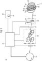
- Fig. 1 shows a highly schematic representation of a structure of a particle therapy system 10.
- the particle therapy system 10 is used for irradiating a arranged on a positioning body with a beam of particles, which is referred to below as the particle beam 12.
- a tumor-damaged tissue of a patient can be irradiated with the particle beam 12 as target volume 14.
- the particle beam system 10 for irradiating a non-living body, in particular a water phantom or another phantom.
- the irradiation of the water phantom can be carried out, for example, for purposes of checking and verifying irradiation parameters before and / or after irradiation of a patient.
- the particle therapy system 10 typically has an accelerator unit 16, for example a synchrotron, a cyclotron or another accelerator, which provides a particle beam 12 with the energy required for the irradiation.
- an accelerator unit 16 for example a synchrotron, a cyclotron or another accelerator, which provides a particle beam 12 with the energy required for the irradiation.
- particles are mainly particles such as protons, pions, helium ions, carbon ions or ions of other elements used.
- a particle beam 12 has a beam diameter of 3-10 mm.
- Layers 18, 20, 22, 24, 26 and 28, which correspond to isoenergy layers, are indicated in the target volume 14 to be irradiated.
- An isoenergy layer 18, 20, 22, 24, 26 or 28 is characterized by the penetration depth of the particle beam 12 at a certain energy of the particle beam 12.
- Each isoenergy layer 18, 20, 22, 24, 26, 28 in the example shown here represents a target area within the target volume 14 which is to be irradiated in the rescanning method.
- a raster scan method is preferably used, in which a particle beam 12 is guided from target point 50 to target point 50 without inevitable shutdown during a transition from one target point 50 to the next. It is also possible to use spot scanning methods with the particle beam being switched off between the individual target points 50 or other scanning methods, such as, for example, continuous scanning methods, in order to irradiate the target area with a rescanning method.
- spot scanning methods with the particle beam being switched off between the individual target points 50 or other scanning methods, such as, for example, continuous scanning methods, in order to irradiate the target area with a rescanning method.
- Fig. 1 some target points 50 of the central isoenergy layer 22 are shown in the target volume 14, which are approached successively with the particle beam 12.
- the particle beam 12 is influenced in its lateral deflection by means of scan magnets 30, ie deflected in its position perpendicular to the beam path direction, also referred to as the x and y direction. Furthermore, an energy modulation device 32 can be provided, with which the energy of the particle beam 12 can be changed quickly, so that the penetration depth of the particle beam 12 can be varied. In this way, a rescanning in the beam direction of the particle beam 12 is possible ("volumetric rescanning", ie the beam path does not have to run within an isoenergy layer).
- the irradiation system 10 also has a sequence controller 36 and detectors 34 for monitoring the beam parameters.
- the arrangement of the components of the particle beam system 10 shown here is merely an example. Also, structures of another arrangement are conceivable.
- the sequence control 36 ie the control system of the system, controls the individual components of the system, such as the accelerator 16, the scan magnets 30 and collects measurement data such as the data of the detectors 34 for monitoring the beam parameters.
- the control is based on an irradiation plan 40, which is determined and provided by means of an irradiation planning device 38.
- the target volume 14 in Fig. 1 has an ellipsoidal shape. If the target volume 14 is to be irradiated overall with a homogeneous nominal dose, this means for the central isoenergy layer 22 that the dose distribution to be applied in the central isoenergy layer 22 is inhomogeneous. This is due to the fact that the central area of the middle isoenergy layer 22 is already loaded by a small dose when the isoenergy layers 24, 26, 28 lying in the beam direction behind the central isoenergy layer 22 are irradiated. For the middle isoenergy layer 22, the dose to be applied is therefore greater at the edge than at the center.
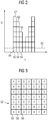
- the dose distribution to be applied to the middle isoenergy layer 22 is for some target points of the middle isoenergy layer in FIG Fig. 2 shown.
- the x-axis indicates the location x of the target points along a line within the middle isoenergy layer, the y-axis the total dose D.
- Dashed lines indicate a threshold value 60, which specifies the minimum fluence-and hereby also specifies the minimum dose to be administered-the application of which can be monitored by the measuring instruments of the particle therapy system 10 with the required accuracy.
- the total inhomogeneous dose 62 to be applied for the middle isoenergy layer 22 is chosen such that the total dose 62 to be applied in the target points 50 is always an integer multiple of a single dose 64. This choice is generally made during the treatment planning and is therefore generally possible without problems, since the single dose 64 is chosen to be so small that it is just above the threshold value 60, that is usually significantly smaller than the total dose 62 to be applied.
- the single dose 64 may be e.g. are below 1.5 times the threshold value 60.
- the choice of the single dose 64 ensures that on the one hand it is ensured that the dose application can be monitored with due accuracy, and that on the other hand as many Rescan passes can be driven to apply the total dose 62 for the middle Isoenergy Mrs 22.
- the isoenergy layer is irradiated by the rescanning method.
- a target point 50 is approached as often as possible during the various rescan passes until the total dose 62 for this target point 50 has been reached.
- the entire single dose 64 can be applied on the basis of the integer ratio.
- Prescribing the single dose causes proximal layers, which are generally irradiated at a lower dose, as these layers are pre-dosed, to be irradiated with fewer rescans.
- proximal layers which are generally irradiated at a lower dose, as these layers are pre-dosed, to be irradiated with fewer rescans.
- this is justifiable since these areas are already covered by the irradiation of distal layers has already been irradiated indirectly in multiple rescan passages.
- settings are generally used in proximal layers, which allow a more accurate dose measurement and therefore smaller threshold values 60. This can be achieved, for example, via a lower intensity of the particle beam and through the choice of a more sensitive measuring range of the measuring devices, such as ionization chambers, with which the dose application of the particle beam is monitored.
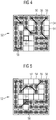
- FIG. 3 to 8 An embodiment of the method according to the invention will be explained with reference to the representation of a fictitious, square isoenergy layer 52.
- the illustrated isoenergy layer 52 is a great simplification of an isoenergy layer which normally occurs in reality. However, the basic principle can be better explained.
- Fig. 3 shows for each target point 50 the total dose to be administered as a multiple of a single dose. It can be seen that the total dose in the peripheral regions of the isoenergy square 52 is greater (ie up to a 4-fold of the single dose) than in the center (only 1-fold of the single dose). This corresponds roughly to the basic principle in Fig. 2 shown inhomogeneous dose distribution.
- Fig. 4 to Fig. 7 shows the approach of the target points for four successive Rescan passes.
- An occupied box 56 means that the target point is approached during the corresponding rescan pass and that the single dose is administered at the target point, whereas an unassigned box 54 means that the target point was not approached during the rescan pass, ie omitted, becomes.
- the target points 50 were distributed to the rescan passages in such a way that a constant number of target points 50 is reached at each rescan pass. Furthermore, in the distribution of the start of the Target points 50 on the Rescan passages ensured that always a continuous scan path 58 can be found so that irradiation in a Rescan passage is possible without interruption.
- the division causes some target points to be approached only in later rescan passes. This makes it possible to find cheap scan paths 58.
- As methods for this known algorithms as they are used in general Traveling-Salesman problems can be used. Especially in the case of complex target areas, as they occur in reality, it may otherwise be the case that non-contiguous islands from target points would have to be approached in a rescan pass. This can be prevented by the described division of the approach of the target points 50 to different Rescan passes.
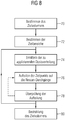
- Fig. 8 shows a schematic representation of the process steps, which are carried out in the planning of irradiation in the rescanning process.
- a target volume is defined in the object to be irradiated (step 70). Subsequently, the target volume is divided into target areas, which are each to be irradiated in several rescan passes (step 72).
- the dose distribution to be applied is determined (step 74).
- This can be a single dose determined, which describes the dose that is delivered in a target point per approach of the target point.
- this single dose can also be determined, for example, from the outset.
- the determination of the dose distribution to be applied can also be carried out under certain boundary conditions, for example it can be stipulated that the total dose to be administered per target point is an integer multiple of a single dose. From the single dose and from the total dose per target point, the number of rescan passes, which must be applied in order to apply the desired dose distribution in the target area.
- the target points or the approach of the target points are distributed to the rescan passes, in such a way that at least one target point, which is not approached with each rescan pass, at least one rescan pass before the last approach of the target point, during which this target point is not approached (step 76).
- step 78 After the approach of the target points has been split up to the rescan passes, it is checked whether the target points can be approached with a scan path that meets predefined criteria at each rescan pass (step 78). For example, it can be checked whether the number of interruptions of the beam, which are necessary in the execution of a scan path, are below a value or are minimized.
- the distribution of the target points or the approach of the target points can be changed in such a way that the resulting scan paths better fulfill the predefined criteria.
- the division of the target points into rescan passes is repeated for each target area in a similar manner. Subsequently, the irradiation of the target volume or the target areas of the target volume according to the irradiation planning (step 80).
- the method can be combined with other methods relating to rescanning.
- the rescan passes may be timed such that desynchronization occurs with the movement of the target volume, it may be performed by a method such as that described in U.S. Pat US 20080078942 A1
- the embodiments which do not fall within the scope of the appended claims are for illustrative purposes only and are not subject of the present invention.
- the invention is defined by the following claims.
Description
Die Erfindung ist in den Ansprüchen definiert. Die Erfindung betrifft ein Verfahren zur Bestrahlungsplanung eines Zielvolumens, ein Verfahren zur Bestrahlung eines Zielbereichs in einem Zielvolumen, eine Bestrahlungsplanungsvorrichtung, eine Steuerungsvorrichtung für eine Bestrahlungsanlage sowie eine Bestrahlungsanlage mit einer derartigen Steuerungsvorrichtung, welche ein Rescanning-Bestrahlungsverfahren implementieren oder ermöglichen. Ein derartiges Bestrahlungsverfahren wird insbesondere zur Bestrahlung von bewegten Zielvolumina eingesetzt zur Kompensation der durch die Bewegung des Zielvolumens hervorgerufenen Bestrahlungsungenauigkeiten.
Die Partikeltherapie ist ein etabliertes Verfahren zur Behandlung von Gewebe, insbesondere von Tumorerkrankungen. Bestrahlungsverfahren, wie sie in der Partikeltherapie eingesetzt werden, finden jedoch auch in nicht-therapeutischen Gebieten Anwendung. Hierzu gehören beispielsweise Forschungsarbeiten, etwa zur Produktentwicklung, im Rahmen der Partikeltherapie, die an nicht-lebenden Phantomen oder Körpern durchgeführt werden, Bestrahlungen von Materialien, etc.
Hierbei werden geladene Partikel wie z.B. Protonen oder Kohlenstoffionen oder andere Ionen auf hohe Energien beschleunigt, zu einem Partikelstrahl geformt und über ein Hochenergiestrahltransportsystem zu einem oder mehreren Bestrahlungsräumen geführt. In dem Bestrahlungsraum wird das zu bestrahlende Zielvolumen mit dem Partikelstrahl bestrahlt.
Es kann dabei vorkommen, dass sich das zu bestrahlende Zielvolumen bewegt. Beispielsweise kann bei der Bestrahlung eines Patienten eine Bewegung des zu bestrahlenden Tumors durch eine Atembewegung verursacht werden. Eine derartige Bewegung kann auch anhand von als Phantomen bezeichneten Modellobjekten für Forschungszwecke nachgebildet werden.The invention is defined in the claims. The invention relates to a method for irradiation planning of a target volume, a method for irradiating a target area in a target volume, an irradiation planning device, a control device for an irradiation system and an irradiation system with such a control device, which implement or enable a rescanning irradiation method. Such an irradiation method is used in particular for the irradiation of moving target volumes for the compensation of the irradiation inaccuracies caused by the movement of the target volume.
Particle therapy is an established method for the treatment of tissue, in particular tumor diseases. Irradiation methods, such as those used in particle therapy, are also used in non-therapeutic areas. These include, for example, research work, for example on product development, in the context of particle therapy, which are performed on non-living phantoms or bodies, irradiation of materials, etc.
In this case, charged particles such as protons or carbon ions or other ions are accelerated to high energies, formed into a particle beam and passed through a high-energy beam transport system to one or more irradiation rooms. In the irradiation room, the target volume to be irradiated is irradiated with the particle beam.
It may happen that the target volume to be irradiated moves. For example, during the irradiation of a patient, a movement of the tumor to be irradiated may be caused by a respiratory movement. Such a movement can also be modeled on model objects known as phantoms for research purposes.
Insbesondere bei Bestrahlungsverfahren, bei denen eine Vielzahl von Bestrahlungsdosen sukzessive an unterschiedlichen Orten im Zielvolumen deponiert werden soll, also bei einem gescannten Partikelstrahl, ist es schwer, eine gewünschte homogene Dosisverteilung im Zielvolumen zu erreichen, wenn sich das Zielvolumen während des Fortgangs der Bestrahlung bewegt.In particular, in irradiation methods in which a plurality of radiation doses is to be deposited successively at different locations in the target volume, ie a scanned particle beam, it is difficult to achieve a desired homogeneous dose distribution in the target volume when the target volume moves during the progress of the irradiation.
Bei einem gescannten Partikelstrahl ist es daher möglich, die zu applizierende Dosis auf mehrere Durchgänge zu verteilen. Dieses Verfahren ist auch unter dem Namen "Rescanning" bekannt. Dies bedeutet, dass ein Zielbereich mehrfach abgefahren wird und dass dort die Gesamtdosis sukzessive durch mehrere, wiederholt applizierte Einzeldosen während der Rescan-Durchgänge aufgebaut wird. Dies hat den Vorteil, dass sich Fehler bei der Dosisdeposition, die bei einem einzigen Durchgang zu einer vollständig fehlerhaft deponierten Dosis führen würde, durch die mehreren Rasterscan-Durchgänge bis zu einem gewissen Grad ausmitteln. Lageunsicherheiten bzgl. des Zielvolumens, Bewegungen des Zielvolumens etc. können so zumindest teilweise kompensiert werden.With a scanned particle beam, it is therefore possible to distribute the dose to be applied over several passes. This method is also known as "rescanning". This means that a target area is traversed multiple times and that there the total dose is built up successively by several, repeatedly applied single doses during the Rescan passes. This has the advantage that errors in the dose deposition that would result in a single pass in a completely erroneously deposited dose through the multiple raster scan passes are averaged out to some degree. Uncertainties regarding the target volume, movements of the target volume, etc. can thus be at least partially compensated.
Der online veröffentliche Vortrag von Silvan Zenklusen et al. "Preliminary investigation for developing repainted beam scanning on the psi gantry 2", erhältlich unter http://ptcog.web.psi.ch/ptcog47_talks.html, schlägt zur Verbesserung vor, bei jedem Zielpunkt eines Bereichs, der mehrfach in mehreren Rescan-Durchgängen gescannt wird, bei jedem Rescan-Durchgang stets eine Dosis zu applizieren, die kleiner ist als eine Obergrenze, ein "Upper-Dose-Limit". Ein Zielpunkt wird in konsekutiven Rescan-Durchgängen so lange bestrahlt, bis seine Soll-Dosis erreicht wurde. In den anschließenden Rescan-Durchgängen wird dieser Zielpunkt von einer weiteren Bestrahlung ausgenommen, d.h. dieser Zielpunkt wird nicht mehr angefahren.The online presentation by Silvan Zenklusen et al. "Preliminary investigation for developing repainted beam scanning on the
Es ist die Aufgabe der Erfindung, ein Verfahren zur Bestrahlungsplanung bzw. ein Verfahren zur Bestrahlung anzugeben, das beim Rescannen eine schnelle und vorteilhafte Ansteuerung der Bestrahlungsanlage erlaubt. Weiterhin ist es die Aufgabe der Erfindung eine entsprechende Bestrahlungsplanungsvorrichtung, Steuerungsvorrichtung für eine Bestrahlungsanlage und Bestrahlungsanlage bereitzustellen.It is the object of the invention to provide a method for irradiation planning or a method for irradiation, which allows a rapid and advantageous control of the irradiation system during rescanning. Furthermore, it is the object of the invention to provide a corresponding irradiation planning device, control device for an irradiation facility and irradiation facility.
Die Erfindung wird gelöst durch die Gegenstände der unabhängigen Ansprüche. Bevorzugte Ausgestaltungen der Erfindung sind in den abhängigen Ansprüchen angegeben und werden im Folgenden näher erläutert. Die vorangehende und die folgende Beschreibung der einzelnen Merkmale bezieht sich sowohl auf die Vorrichtungskategorie als auch auf die Verfahrenskategorie, ohne dass dies im Einzelnen in jedem Fall explizit erwähnt ist; die dabei offenbarten Einzelmerkmale können auch in anderen als den gezeigten Kombinationen erfindungswesentlich sein.The invention is solved by the subject matters of the independent claims. Preferred embodiments of the invention are specified in the dependent claims and are explained in more detail below. The preceding and following description of the individual features relates both to the device category and to the process category, without this being explicitly mentioned in each case explicitly; The individual features disclosed in this case can also be essential to the invention in combinations other than those shown.
Das erfindungsgemäße Verfahren zur Bestrahlungsplanung eines Zielvolumens umfasst folgende Schritte:
- Festlegen eines Zielbereichs mit einzeln anfahrbaren Zielpunkten,
- Festlegen einer Anzahl von Rescan-Durchgängen, in denen der Zielbereich mehrfach abgescannt wird, derart, dass die Zielpunkte des Zielbereichs während der Rescan-Durchgänge unterschiedlich oft angefahren werden, wodurch zumindest ein Teil der Zielpunkte nicht bei jedem Rescan-Durchgang angefahren wird,
- Defining a target area with individually approachable destination points,
- Determining a number of rescan passes in which the target area is scanned multiple times, such that the target areas of the target area are approached a different number of times during the rescan passes, whereby at least a part of the target points is not approached with each rescan pass,
Das zu bestrahlende Zielvolumen ist dabei üblicherweise in eine Mehrzahl von Zielbereichen aufgeteilt. Während einer Bestrahlungssitzung werden die Zielbereiche im Rescanning-Verfahren bestrahlt, d.h. jeweils mit mehreren Rescan-Durchgängen. Die Zielbereiche werden dabei üblicherweise sukzessive abgetastet, d.h., sobald ein Zielbereich im Rescanning-Verfahren abgetastet wurde, wird der nächste Zielbereich wiederum im Rescanning Verfahren abgetastet, usw.The target volume to be irradiated is usually divided into a plurality of target areas. During an irradiation session The target areas are irradiated in the rescanning process, ie each with multiple Rescan passes. The target areas are usually scanned successively, ie, as soon as a target area has been scanned in the rescanning method, the next target area is again scanned in the rescanning method, etc.
Insbesondere kann die Dosisverteilung, die für den Zielbereich festgelegt wird, inhomogen sein. Selbst wenn die Gesamtdosis, die für das Zielvolumen appliziert werden soll, eine homogene Dosisverteilung aufweist, kann es notwendig sein, dass die zu applizierende Dosisverteilung für einen Zielbereich inhomogen ist. Dies rührt daher, dass Teile des Zielbereichs bereits während der Bestrahlung anderer Zielbereiche mit einer Vor-Dosis belegt wurden. Die Dosisverteilung kann dabei ein Maß für die zu applizierende Partikelzahl darstellen. Die Dosisverteilung kann unter Berücksichtigung von Planungsvorgaben hinsichtlich Zielvolumen, der im Zielvolumen zu deponierenden Dosis und/oder der effektiven Wirkung der im Gewebe deponierten Dosis - beispielsweise charakterisierbar durch die Angabe der relativen biologische Wirksamkeit (RBW bzw. RBE) - in einer Planungsphase ermittelt werden.In particular, the dose distribution that is set for the target area may be inhomogeneous. Even if the total dose to be applied for the target volume has a homogeneous dose distribution, it may be necessary for the dose distribution to be administered to be inhomogeneous for a target area. This is because parts of the target area have already been pre-dosed during irradiation of other target areas. The dose distribution can represent a measure of the number of particles to be applied. The dose distribution can be determined in a planning phase taking account of planning specifications with regard to target volume, the dose to be deposited in the target volume and / or the effective effect of the dose deposited in the tissue - for example charac- terizable by the indication of the relative biological efficacy (RBW or RBE).
Bei dem erfindungsgemäßen Verfahren wird die Dosisverteilung für den Zielbereich dadurch appliziert, dass die Zielpunkte des Zielbereichs während der Rescan-Durchgänge unterschiedlich oft angefahren werden. Unter "Anfahren eines Zielpunktes" wird dabei verstanden, dass in dem Zielpunkt eine Einzeldosis appliziert wird bzw. dass dies geplant ist. Insbesondere eine inhomogene Dosisverteilung kann auf diese Weise einfach appliziert werden. So kann beispielsweise ein Zielpunkt, für den eine höhere Gesamtdosis vorgesehen ist, während der Rescan-Durchgänge insgesamt öfter angefahren werden als ein Zielpunkt, für den eine geringere Gesamtdosis vorgesehen ist.In the method according to the invention, the dose distribution for the target area is applied in that the target points of the target area are approached different times during the rescan passages. By "approaching a target point" is meant that in the target point a single dose is applied or that this is planned. In particular, an inhomogeneous dose distribution can be easily applied in this way. Thus, for example, a target point for which a higher total dose is provided can be approached more often during the rescan passages than a target point for which a lower total dose is provided.
Dadurch, dass die Zielpunkte des Zielbereichs unterschiedlich oft angefahren werden, ergibt sich, dass zumindest ein Teil der Zielpunkte bei bestimmten Rescan-Durchgängen nicht angefahren wird. Wenn beispielsweise insgesamt 10 Rescan-Durchgänge vorgesehen sind, ein Zielpunkt jedoch nur siebenmal insgesamt angefahren werden soll, existieren 3 Rescan-Durchgänge, bei denen der Zielpunkt nicht angefahren wird, d.h. übersprungen wird.The fact that the target points of the target area are approached differently often, it follows that at least a part the target points are not approached during certain Rescan passes. If, for example, a total of 10 rescan passes are provided, but a target point is to be approached only seven times in total, there are 3 rescan passes in which the target point is not approached, ie is skipped.
Der Erfindung liegt die Idee zu Grunde, dass es vorteilhaft ist, wenn das Anfahren der Zielpunkte derart auf die Rescan-Durchgänge aufgeteilt wird, dass bei zumindest einem Zielpunkt, der nicht in jedem Rescan-Durchgang angefahren wird, vor dem letzten Rescan-Durchgang, bei dem dieser Zielpunkt angefahren wird, zumindest ein weiterer Rescan-Durchgang liegt, bei dem dieser Zielpunkt nicht angefahren wird. Dies kann beispielsweise erreicht werden, indem dieser Zielpunkt nicht bei dem ersten Rescan-Durchgang angefahren wird. Dies kann aber auch erreicht werden, indem bei einem Zielpunkt, der bei zumindest zwei Rescan-Durchgängen angefahren wird, zwischen diesen zwei Rescan-Durchgängen zumindest ein weiterer Rescan-Durchgang liegt, bei dem der Zielpunkt nicht angefahren wird.The invention is based on the idea that it is advantageous if the approach of the target points is distributed to the rescan passes in such a way that at least one target point, which is not approached in each rescan pass, before the last rescan pass, in which this target point is approached, at least one further Rescan-passage is in which this target point is not approached. This can be achieved, for example, by not approaching this target point on the first rescan pass. However, this can also be achieved by at least one further rescan pass lies at a target point, which is approached in at least two Rescan passes, between these two Rescan passes, in which the target point is not approached.
Es ist zwar vorteilhaft, wenn beim Rescannen die Zielpunkte unterschiedlich oft angefahren werden. Dadurch ist es nämlich möglich, eine inhomogene Dosisapplikation zu gewährleisten und gleichzeitig darauf zu achten, dass keine Einzeldosis, die an einem Zielpunkt appliziert wird, derart klein wird, dass mit den Messinstrumenten eine sichere Überwachung der Applikation der Einzeldosis nicht mehr gewährleistet werden kann.Although it is advantageous if the target points are approached different times during rescanning. This makes it possible to ensure an inhomogeneous dose application and at the same time to make sure that no single dose that is applied to a target point becomes so small that reliable monitoring of the application of the single dose can no longer be guaranteed with the measuring instruments.
Es wurde aber auch erkannt, dass es problematisch ist, wenn bei wiederholten Rescan-Durchgängen die Zielpunkte solange angefahren werden, bis die Gesamtdosis pro Zielpunkt appliziert worden ist und diese Zielpunkte in folgenden Rescan-Durchgängen nicht mehr angefahren werden. Durch dieses "starre" Schema dünnt sich die Menge der Zielpunkte aus, die in einem Rescan-Durchgang angefahren werden. Dies ist aber unvorteilhaft für eine Bestrahlungsanlage. Wenn in einem späteren Rescan-Durchgang, bei dem die Zielpunkte ausgedünnt sind, der Strahl deshalb zu oft unterbrochen werden muss, beispielsweise um von einer verbleibenden Insel von Zielpunkten zur nächsten verbleibenden Insel zu gelangen, erhöht dies die Bestrahlungszeit.However, it has also been recognized that it is problematic if, during repeated rescan passes, the target points are approached until the total dose per target point has been applied and these target points are no longer approached in the following rescan passes. This "rigid" scheme thins out the amount of target points approached in a rescan run. This is unfavorable for an irradiation facility. Therefore, if, in a later rescan run, where the target points are thinned out, the beam must be interrupted too often, for example to get from one remaining island from target points to the next remaining island, this will increase the exposure time.
Dieses starre Schema ist durch das vorliegende Planungsverfahren aufgebrochen. Hierdurch ist es möglich, die Bestrahlung eines Zielpunktes auf einen späteren Zeitpunkt, d.h. auf einen späteren Rescan-Durchgang zu verschieben. Dies ermöglicht es, die beschriebenen negativen Effekte zu verringern oder zu vermeiden.This rigid scheme has broken through the present planning process. This makes it possible to reduce the irradiation of a target point to a later time, i. to move to a later rescan run. This makes it possible to reduce or avoid the described negative effects.
Beispielsweise kann ein Zielpunkt, der erst bei einem späteren Rescan-Durchgang angefahren wird, dazu verwendet werden, die verbleibenden Inseln des späteren Rescan-Durchgangs zu verbinden. Hierdurch kann der Strahlpfad, der während des späteren Rescan-Durchgangs abgefahren wird, flexibel optimiert werden. Auch wenn üblicherweise mehrere Zielpunkte verwendet werden, um die verbleibenden Inseln eines späteren Rescan-Durchgang zu verbinden, kann - je nach Konstellation der Geometrie des Zielbereichs und der zu applizierenden Dosisverteilung - bereits ein einzelner Zielpunkt, der erst während eines späteren Rescan-Durchgangs angefahren wird, zu einer verbesserten Ausführung der Rescan-Durchgänge führen.For example, a target point that is approached only on a later rescan pass can be used to connect the remaining islands of the later rescan pass. As a result, the beam path that is traversed during the later rescan pass can be flexibly optimized. Even if usually several target points are used to connect the remaining islands of a later rescan pass, depending on the constellation of the geometry of the target area and the dose distribution to be applied, a single target point can be approached only during a later rescan pass , lead to improved execution of the rescan passes.
Die während der Rescan-Durchgänge anzufahrenden Zielpunkte können aber auch derart aufgeteilt werden, dass nun möglichst gleichmäßig viele Zielpunkte pro Rescan-Durchgang angefahren werden, d.h. dass die Zahl der Zielpunkte, die bei jedem Durchgang angefahren werden, im Wesentlichen gleich ist. Diese im Wesentlichen gleichmäßige Verteilung bewirkt, dass ein "Ausdünnen" nicht oder in nur sehr geringem Maße auftritt. Dies kann beispielsweise dadurch erreicht werden, dass bei jedem Rescan-Durchgang ein oder mehrere Zielpunkte existieren, die nicht angefahren werden. Die Zielpunkte und die Anzahl der Anfahrten pro Zielpunkt können statistisch über die Rescan-Durchgänge verteilt werden.However, the target points to be approached during the rescan passes can also be divided in such a way that many target points per rescan pass are approached as uniformly as possible, ie, the number of target points approached on each pass is essentially the same. This substantially uniform distribution causes "thinning out" does not occur or only to a very limited extent. This can be achieved, for example, by the fact that with each rescan pass one or more target points exist that are not approached. The target points and the number The approaches per destination can be statistically distributed via the rescan passes.
Eine Möglichkeit, das Aufteilen der Zielpunkte auf die Rescan-Durchgänge vorzunehmen, ist es das Aufteilen im Hinblick auf den Scan-Pfad vorzunehmen, und zwar derart, dass ein Scan-Pfad, mit dem in einem der Rescan-Durchgänge die anzufahrenden Zielpunkte angefahren werden, ein vordefiniertes Kriterium erfüllt. Beispielsweise kann nach einem Aufteilen der Zielpunkte geprüft werden, ob bei jedem Rescan-Durchgang der daraus resultierende Scan-Pfad die vordefinierten Kriterien erfüllt. Falls dies nicht der Fall ist, kann das Aufteilen der Zielpunkte verändert werden. Das Aufteilen kann auch von vornherein so gestaltet werden, dass bei dem durchzuführenden Algorithmus bestimmte Kombinationen von Zielpunkten und Rescan-Durchgängen nicht erlaubt oder bestraft werden.One way of performing the splitting of the target points on the rescan passes is to perform the splitting with respect to the scan path, such that a scan path is used to approach the target points to be approached in one of the rescan passes , meets a predefined criterion. For example, after splitting the target points, it can be checked whether the resulting scan path fulfills the predefined criteria for each rescan run. If this is not the case, the splitting of the target points can be changed. The splitting can also be designed a priori so that certain combinations of target points and rescan passes are not allowed or punished in the algorithm to be performed.
Das vordefinierte Kriterium kann beispielsweise sein, dass in einem Scan-Pfad ein Abstand zwischen zwei nacheinander anzufahrenden Zielpunkten unterhalb einer Schwelle liegt. Beispielsweise kann festgelegt werden, dass der maximale Abstand zwischen zwei Zielpunkten geringer als 20 mm, insbesondere geringer als 10 mm oder 5 mm ist. In diesem Fall kann nämlich das Scannen erfolgen, ohne dass eine Abschaltung des Strahls zwischen den zwei Zielpunkten zwingend notwendig ist. Andere mögliche Kriterien können sein: Die Anzahl der notwendigen Unterbrechungen des Strahls beim Abfahren des Scan-Pfads, welche es zu minimieren gilt oder welche unterhalb eines Schwellwertes liegen sollen.The predefined criterion may be, for example, that in a scan path a distance between two target points to be approached in succession is below a threshold. For example, it can be determined that the maximum distance between two target points is less than 20 mm, in particular less than 10 mm or 5 mm. In this case, namely, the scanning can be done without a shutdown of the beam between the two target points is mandatory. Other possible criteria can be: The number of necessary interruptions of the beam when scanning the scan path, which should be minimized or which should be below a threshold value.
In einer vorteilhaften Ausführungsvariante wird das Planungsverfahren dahin gehend ausgestaltet, dass bei einem Zielpunkt die zu applizierende Gesamtdosis ein ganzzahliges Vielfaches der bei diesem Zielpunkt zu applizierenden Einzeldosis ist, die immer dann appliziert wird, wenn der Zielpunkt in einem Rescan-Durchgang angefahren wird. Diese Einschränkung hat den Vorteil, dass in jedem Zielpunkt stets die gesamte Einzeldosis appliziert werden kann. Die Applikation von Bruchteilen der Einzeldosis, die mitunter problematisch ist, da sie eventuell nicht mit der gebotenen Genauigkeit überwacht werden kann, wird dadurch vermieden.In an advantageous embodiment variant, the planning method is designed such that at a target point the total dose to be administered is an integer multiple of the single dose to be applied at this target point, which is always applied when the target point is approached in a rescan run. This restriction has the advantage that the entire single dose can always be administered in each target point. The application of fractions The single dose, which is sometimes problematic because it may not be monitored with the required accuracy, is thereby avoided.
Auch diese Ausführungsvariante kann unabhängig von dem offenbarten Verfahren implementiert werden. Dies bedeutet, dass beim Rescanning bzw. bei einer Bestrahlungsplanung für ein Rescanning-Verfahren pro Zielpunkt lediglich Verhältnisse zwischen Gesamtdosis und Einzeldosis zugelassen werden, die ganzzahlig sind. Auf diese Weise kann sichergestellt werden, dass pro Zielpunkt stets die gesamte Einzeldosis appliziert wird. Implementieren lässt sich eine derartige Ausgestaltung z.B. durch Vorgabe von Randbedingungen, welche die Freiheiten bei der Bestimmung der Bestrahlungsparameter einschränken. Beispielsweise kann auch die räumliche Lage der Zielpunkte so gewählt werden, dass sich diese Vorgabe erfüllen lässt. Die Einzeldosis, die dem ganzzahligen Verhältnis zu Grunde liegt, kann für den gesamten Bestrahlungsplan gleich gewählt werden, oder auch für unterschiedliche Abschnitte des Bestrahlungsplans - wie für unterschiedliche Zielbereiche - unterschiedlich.This embodiment variant can also be implemented independently of the disclosed method. This means that in rescanning or in a radiation planning for a rescanning procedure per target point only ratios between total dose and single dose are allowed, which are integer. In this way it can be ensured that the entire single dose is always administered per target point. Such a design can be implemented, for example. by specifying boundary conditions which limit the freedom in the determination of the irradiation parameters. For example, the spatial position of the target points can be chosen so that this requirement can be met. The single dose, which is based on the integer ratio, can be chosen to be the same for the entire treatment plan, or different for different sections of the treatment plan - as for different target areas.
Es ist vorteilhaft, die Einzeldosis derart klein zu wählen, dass sie gerade noch oberhalb eines Schwellwertes liegt. Hierdurch lässt sich nämlich sicherstellen, dass die Dosisapplikation genau überwacht werden kann. Wenn eine Einzeldosis nämlich zu klein würde, gelingt es mitunter nicht mehr, die Einzeldosis mit hinreichender Genauigkeit durch die Messinstrumente zu überwachen, was letztlich den Behandlungserfolg gefährden kann.It is advantageous to select the single dose so small that it is just above a threshold. This ensures that the dose application can be accurately monitored. If a single dose would be too small, it may no longer be possible to monitor the single dose with sufficient accuracy by the measuring instruments, which can endanger the success of the treatment.
Auch unabhängig von den offenbarten Verfahren kann es vorteilhaft sein, die in einem Zielpunkt zu applizierende Einzeldosis, also die Dosis, die bei einem Anfahren des Zielpunktes appliziert wird, insbesondere beim Rescanning so zu wählen, dass die Einzeldosis stets oberhalb eines vorgegebenen Schwellwertes liegt. Auf diese Weise kann sichergestellt werden, dass die Einzeldosis noch von Messinstrumenten, mit denen die Dosisapplikation überwacht wird, mit der gebotenen Genauigkeit überwacht werden kann. Die Einzeldosis kann auf die Wahl des Messbereichs der Messinstrumente und auf die extrahierte Intensität aus dem Beschleuniger abgestimmt sein; insgesamt werden die Möglichkeiten der verwendeten Hardware explizit berücksichtigt. Falls im Laufe der Bestrahlung die Hardware in einem anderen Betriebsmodus betrieben wird, z.B. mit geänderter extrahierter Intensität und/oder mit einer anderen Wahl des Messbereichs der Detektoren, kann der vorgegebene Schwellwert angepasst werden.Independently of the disclosed methods, it can also be advantageous to select the single dose to be applied in a target point, ie the dose that is applied when the target point approaches, in particular during rescanning, so that the single dose always lies above a predetermined threshold value. In this way, it can be ensured that the single dose is still covered by measuring instruments, with which the dose application is monitored can be monitored with the required accuracy. The single dose may be tailored to the choice of measuring range of the measuring instruments and to the extracted intensity from the accelerator; Overall, the possibilities of the hardware used are explicitly taken into account. If, in the course of irradiation, the hardware is operated in a different operating mode, eg with a changed extracted intensity and / or with a different choice of the measuring range of the detectors, the predetermined threshold value can be adapted.
Dennoch soll die Einzeldosis innerhalb dieser Vorgabe möglichst klein gewählt werden, da dann nämlich die Anzahl der Rescan-Durchgänge erhöht wird und somit die positiven Effekte des Rescanning deutlicher hervortreten. Zudem kann die Vorgabe "Gesamtdosis ist ein ganzzahliges Vielfaches der Einzeldosis" einfacher erfüllt werden. Beispielsweise kann die Einzeldosis stets unterhalb des Zehnfachen bzw. des Fünffachen des Schwellwertes liegen, insbesondere unterhalb des Zweifachen des Schwellwertes. Bestrahlungsplanungsvorrichtungen bzw. Steuerungsvorrichtungen für Bestrahlungsanlagen können entsprechend ausgebildet werden.Nevertheless, the single dose should be chosen as small as possible within this specification, since then the number of rescan passages is increased and thus the positive effects of rescanning become more pronounced. In addition, the prescription "total dose is an integer multiple of the single dose" can be fulfilled more easily. For example, the single dose may always be below ten times or five times the threshold, in particular below twice the threshold. Irradiation planning devices or control devices for irradiation facilities can be designed accordingly.
In einer vorteilhaften Ausführung wird bei den Zielpunkten des Zielbereichs stets jeweils eine gleich große Einzeldosis appliziert. Diese Ausführungsvariante ist besonders geeignet, auf einer Bestrahlungsanlage installiert zu werden, weil eine Bestrahlungsanlage auf die zu applizierende gleichgroße Einzeldosis hin ausgelegt und optimiert werden kann. Beispielsweise können die Messbereiche der Vorrichtungen, mit denen die Applikation der Einzeldosis überwacht wird, auf die Größe der Einzeldosis abgestimmt werden. Des Weiteren kann es beim Rescanning und insbesondere beim volumetrischen Rescanning auftreten, dass die Bestrahlung ohne Umschalten von Isoenergieschichten und/oder ohne Umschalten der Intensität, mit der der Partikelstrahl von der Beschleunigereinheit extrahiert wird, und/oder ohne Umschalten der Messbereiche der Messvorrichtungen wie z.B. des Ionisationskammersystems erfolgt, was in einer gleich großen Einzeldosis resultiert.In an advantageous embodiment, an equally large single dose is always applied at the target points of the target area. This embodiment variant is particularly suitable for being installed on an irradiation facility because an irradiation facility can be designed and optimized for the same single dose to be administered. For example, the measuring ranges of the devices with which the administration of the single dose is monitored can be adapted to the size of the single dose. Furthermore, during rescanning, and in particular volumetric rescanning, irradiation may occur without switching isoenergy layers and / or without switching over the intensity with which the particle beam is extracted by the accelerator unit and / or without switching over the measuring ranges of the measuring devices such as the ionization chamber system, resulting in an equal single dose.
Es ist dabei nicht notwendig, den Zielbereich komplett mit allen Rescan-Durchgängen abzuscannen, bevor zu einem weiteren Zielbereich des Zielvolumens übergegangen wird, der dann seinerseits mit verschiedenen Rescan-Durchgängen bestrahlt wird. Bereits während einiger Rescan-Durchgänge, mit denen der eine Zielbereich bestrahlt wird, können Zielpunkte eines anderen Zielbereichs angefahren werden. Auch durch dieses "Verweben" der Rescan-Durchgänge für den einen Zielbereich mit den Rescan-Durchgängen des anderen Zielbereichs kann ein vorteilhaftes Anfahren der Zielpunkte erreicht werden. Wenn bei einem Rescan-Durchgang beispielsweise nur mehr wenige Zielpunkte eines Zielbereichs angefahren werden müssten, ist es denkbar, diese Zielpunkte auch in einem anderen Rescan-Durchgang des anderen Zielbereichs unterzubringen. D.h. mitunter ist es vorteilhaft, noch einen Teil der Zielpunkte eines Zielbereichs erst dann zu abzufahren, wenn bereits die Bestrahlung eines anderer Zielbereichs begonnen wurde. Auch dieses Verfahren kann unabhängig von den offenbarten Verfahren implementiert werden. Bestrahlungsplanungsvorrichtungen bzw. Steuerungsvorrichtungen für Bestrahlungsanlagen können entsprechend ausgebildet werden.It is not necessary to scan the target area completely with all rescan passes before proceeding to another target area of the target volume, which in turn is then irradiated with different rescan passes. Already during some Rescan passes, with which one target area is irradiated, target points of another target area can be approached. Also by this "weaving" of the Rescan passages for the one target area with the Rescan passes of the other target area, an advantageous approach of the target points can be achieved. If, for example, only a few target points of a target area need to be approached during a rescan pass, it is conceivable to accommodate these target points in another rescan pass of the other target area. That Sometimes it is advantageous to leave only a part of the target points of a target area only when the irradiation of another target area has already been started. Also, this method can be implemented independently of the disclosed methods. Irradiation planning devices or control devices for irradiation facilities can be designed accordingly.
Das erfindungsgemäße Verfahren zur Bestrahlung eines Zielbereichs in einem Zielvolumen ist dahingehend ausgestaltet, dass der Zielbereich einzeln anzufahrende Zielpunkte umfasst und dass im Zielbereich insbesondere eine inhomogene Dosisverteilung appliziert wird. Der Zielbereich wird mit einer Vielzahl von Rescan-Durchgängen bestrahlt, d.h. der Zielbereich wird insgesamt also mehrfach abgescannt. Die Zielpunkte des Zielbereichs selbst werden während der Rescan-Durchgänge unterschiedlich oft angefahren, so dass zumindest ein Teil der Zielpunkte nicht bei jedem Rescan-Durchgang angefahren wird. Das Verfahren ist dahingehend ausgestaltet, dass bei zumindest einem Zielpunkt, der nicht in jedem Rescan-Durchgang angefahren wird, vor dem letzten Rescan-Durchgang, bei dem dieser Zielpunkt angefahren wird, zumindest ein weiterer Rescan-Durchgang ausgeführt wird, bei dem dieser Zielpunkt nicht angefahren wird.The method according to the invention for irradiating a target area in a target volume is designed in such a way that the target area comprises target points to be approached individually and that in particular an inhomogeneous dose distribution is applied in the target area. The target area is irradiated with a multitude of rescan passes, ie the target area is thus scanned several times in total. The target points of the target area itself are approached a different number of times during the rescan passes, so that at least part of the target points are not approached with each rescan pass. The method is designed such that at least one target point that is not approached in each rescan pass before the last rescan pass, in which this target point is approached, at least one further Rescan-passage is performed, in which this target point is not approached.
Die erfindungsgemäße Bestrahlungsplanungsvorrichtung weist eine Rechnereinheit auf, welche zur Durchführung eines der offenbarten Verfahren zur Bestrahlungsplanung ausgebildet ist. Dies kann beispielsweise mithilfe eines geeigneten Computerprogramms geschehen.The irradiation planning device according to the invention has a computer unit which is designed to carry out one of the disclosed methods for irradiation planning. This can be done, for example, by using a suitable computer program.
Die erfindungsgemäße Steuerungsvorrichtung für eine Bestrahlungsanlage weist einen Steuerungsrechner auf, der eine Bestrahlungsanlage während eine Bestrahlung derart steuert, dass eines der offenbarten Verfahren zur Bestrahlung eines Zielbereichs in einem Zielvolumen ausgeführt wird. Auch dies kann mit einem geeigneten Computerprogramm geschehen. Die erfindungsgemäße Bestrahlungsanlage weist eine derartige Steuerungsvorrichtung auf.The irradiation facility control apparatus according to the present invention includes a control computer that controls an irradiation facility during irradiation to perform one of the disclosed methods for irradiating a target area in a target volume. This can also be done with a suitable computer program. The irradiation system according to the invention has such a control device.
Ausgestaltungen und Vorteile, wie sie für das Verfahren zur Bestrahlungsplanung aufgeführt und erläutert worden sind, gelten ebenso für das Verfahren zur Bestrahlung eines Zielbereichs in einem Zielvolumen, und in entsprechender Weise für die Bestrahlungsplanungsvorrichtung und für die Steuerungsvorrichtung für eine Bestrahlungsanlage.Embodiments and advantages that have been listed and explained for the method for irradiation planning also apply to the method for irradiating a target area in a target volume, and in the same way for the irradiation planning device and for the control device for an irradiation facility.
Ausführungsformen der Erfindung mit Weiterbildungen gemäß den Merkmalen der abhängigen Ansprüche werden anhand der folgenden Zeichnung näher erläutert ohne jedoch darauf beschränkt zu sein. Es zeigen:
-
Fig. 1 eine schematische Übersicht über eine Bestrahlungsanlage, mit der ein Rescanning-Verfahren durchgeführt werden kann, -
Fig. 2 ein Diagramm zur Darstellung einer inhomogene Dosisverteilung, die in einer der Isoenergieschichten zu applizieren ist, -
Fig. 3 eine schematische Darstellung einer zu applizierenden Dosisverteilung in einem Zielbereich, -
Fig. 4 bis Fig. 7 die Darstellung vier nacheinander auszuführender Rescan-Durchgänge mit einer Darstellung der Zielpunkte, die im jeweiligen Rescan-Durchgang angefahren werden, -
Fig. 8 eine schematische Darstellung der Verfahrensschritte, die bei einer Ausführungsform der Erfindung durchgeführt werden.
-
Fig. 1 a schematic overview of an irradiation facility with which a rescanning process can be performed, -
Fig. 2 a diagram for illustrating an inhomogeneous dose distribution to be applied in one of the isoenergy layers, -
Fig. 3 a schematic representation of a dose distribution to be applied in a target area, -
Fig. 4 to Fig. 7 the representation of four consecutively executed rescan passages with a representation of the target points which are approached in the respective rescan pass, -
Fig. 8 a schematic representation of the method steps that are performed in an embodiment of the invention.
Die Partikeltherapieanlage 10 weist typischerweise eine Beschleunigereinheit 16 auf, z.B. ein Synchrotron, ein Zyklotron oder einen sonstigen Beschleuniger, der einen Partikelstrahl 12 mit der zur Bestrahlung notwendigen Energie bereitstellt. Als Partikel werden vornehmlich Teilchen wie beispielsweise Protonen, Pionen, Heliumionen, Kohlenstoffionen oder Ionen anderer Elemente eingesetzt. Typischerweise hat ein Partikelstrahl 12 einen Strahldurchmesser von 3-10 mm.The
In dem zu bestrahlenden Zielvolumen 14 sind Schichten 18, 20, 22, 24, 26 und 28 angedeutet, welche Isoenergieschichten entsprechen. Eine Isoenergieschicht 18, 20, 22, 24, 26 oder 28 ist durch die Eindringtiefe des Partikelstrahls 12 bei einer bestimmten Energie des Partikelstrahls 12 gekennzeichnet. Jede Isoenergieschicht 18, 20, 22, 24, 26, 28 stellt bei dem hier gezeigten Beispiel einen Zielbereich innerhalb des Zielvolumens 14 dar, der im Rescanning-Verfahren bestrahlt werden soll.
Als Scanverfahren wird bevorzugt ein Rasterscan-Verfahren verwendet, bei dem ein Partikelstrahl 12 von Zielpunkt 50 zu Zielpunkt 50 geführt wird ohne zwangsläufige Abschaltung bei einem Übergang von einem Zielpunkt 50 zum nächsten. Es können auch Spotscan-Verfahren mit Abschaltung des Partikelstrahls zwischen den einzelnen Zielpunkten 50 oder andere ScanVerfahren wie beispielsweise kontinuierliche Scanverfahren eingesetzt werden, um den Zielbereich mit einem Rescanning-Verfahren zu bestrahlen. In
Der Partikelstrahl 12 wird in seiner lateralen Auslenkung mithilfe von Scan-Magneten 30 beeinflusst, d.h. in seiner Position senkrecht zu Strahlverlaufsrichtung, auch als x- und y-Richtung bezeichnet, abgelenkt. Weiterhin kann eine Energiemodulationsvorrichtung 32 vorgesehen sein, mit der die Energie des Partikelstrahls 12 schnell geändert werden kann, so dass die Eindringtiefe des Partikelstrahls 12 variiert werden kann. Auf diese Weise ist auch ein Rescanning in Strahlrichtung des Partikelstrahls 12 möglich ("volumetrisches Rescanning", d.h. der Strahlpfad muss nicht innerhalb einer Isoenergieschicht verlaufen).The
Die Bestrahlungsanlage 10 weist ferner eine Ablaufsteuerung 36 und Detektoren 34 zur Überwachung der Strahlparameter auf. Die Anordnung der hier gezeigten Komponenten der Partikelstrahlanlage 10 ist lediglich beispielhaft. Auch Aufbauten einer anderen Anordnung sind denkbar.The
Die Ablaufsteuerung 36, also das Kontrollsystem der Anlage, steuert die einzelnen Komponenten der Anlage, wie beispielsweise den Beschleuniger 16, die Scan-Magnete 30 und sammelt Messdaten wie beispielsweise die Daten der Detektoren 34 zur Überwachung der Strahlparameter. Üblicherweise erfolgt die Steuerung basierend auf einem Bestrahlungsplan 40, der mithilfe einer Bestrahlungsplanungseinrichtung 38 ermittelt und bereitgestellt wird.The
In einer hier gezeigten Partikeltherapieanlage 10 können Ausführungsformen der Erfindung implementiert werden. Mögliche Ausführungsformen werden anhand der nachfolgenden Zeichnung näher erläutert.In a
Das Zielvolumen 14 in
Die Dosisverteilung, die bei der mittleren Isoenergieschicht 22 zu applizieren ist, ist für einige Zielpunkte der mittleren Isoenergieschicht in
Gestrichelt eingezeichnet ist ein Schwellwert 60, der die minimale Fluenz angibt - und hierüber auch die minimale zu applizierende Dosis festlegt -, deren Applikation durch die Messinstrumente der Partikeltherapieanlage 10 mit der gebotenen Genauigkeit überwacht werden kann.Dashed lines indicate a
Die zu applizierende, inhomogene Gesamtdosis 62 für die mittlere Isoenergieschicht 22 ist dabei derart gewählt, dass die in den Zielpunkten 50 jeweils zu applizierende Gesamtdosis 62 stets ein ganzzahliges Vielfaches einer Einzeldosis 64 ist. Diese Wahl wird im Allgemeinen während der Bestrahlungsplanung getroffen und ist deshalb im Allgemeinen problemlos möglich, da die Einzeldosis 64 so klein gewählt ist, dass sie knapp oberhalb des Schwellwertes 60 liegt, also üblicherweise deutlich kleiner als die zu applizierende Gesamtdosis 62 ist. Die Einzeldosis 64 kann z.B. unterhalb des 1,5 fachen des Schwellwertes 60 liegen. Die Wahl der Einzeldosis 64 bewirkt, dass einerseits sichergestellt ist, dass die Dosisapplikation mit gebotener Genauigkeit überwacht werden kann, und dass andererseits möglichst viele Rescan-Durchgänge gefahren werden können, um die Gesamtdosis 62 für die mittlere Isoenergieschicht 22 zu applizieren.The total
Die Isoenergieschicht wird im Rescanning-Verfahren bestrahlt. Ein Zielpunkt 50 wird dabei während der verschiedenen Rescan-Durchgänge insgesamt sooft angefahren, bis die Gesamtdosis 62 für diesen Zielpunkt 50 erreicht worden ist. Bei jedem Anfahren eines Zielpunktes 50 kann die gesamte Einzeldosis 64 aufgrund des ganzzahligen Verhältnisses appliziert werden.The isoenergy layer is irradiated by the rescanning method. In the process, a
Die Vorgabe der Einzeldosis bewirkt, dass proximale Schichten, welche im allgemeinen mit einer geringeren Dosis bestrahlt werden, da diese Schichten mit einer Vor-Dosis belegt sind, mit weniger Rescan-Durchgängen bestrahlt werden. Dies ist allerdings vertretbar, da diese Bereiche bereits durch die Bestrahlung distaler Schichten bereits indirekt in vielfachen Rescan-Durchgängen bestrahlt worden sind. Des Weiteren werden in proximalen Schichten in der Regel Einstellungen verwendet, die eine genauere Dosismessung und demnach kleinere Schwellwerte 60 erlauben. Dies kann z.B. über eine geringere Intensität des Partikelstrahls und durch die Wahl eines sensitiveren Messbereichs der Messvorrichtungen wie Ionisationskammern erreicht werden, mit welchen die Dosisapplikation des Partikelstrahls überwacht wird.Prescribing the single dose causes proximal layers, which are generally irradiated at a lower dose, as these layers are pre-dosed, to be irradiated with fewer rescans. However, this is justifiable since these areas are already covered by the irradiation of distal layers has already been irradiated indirectly in multiple rescan passages. Furthermore, settings are generally used in proximal layers, which allow a more accurate dose measurement and therefore smaller threshold values 60. This can be achieved, for example, via a lower intensity of the particle beam and through the choice of a more sensitive measuring range of the measuring devices, such as ionization chambers, with which the dose application of the particle beam is monitored.
Mithilfe von
Die Zielpunkte 50 wurden dabei derart auf die Rescan-Durchgänge verteilt, dass bei jedem Rescan-Durchgang eine möglichst gleichbleibende Anzahl an Zielpunkten 50 angefahren wird. Weiterhin wurde bei der Verteilung des Anfahrens der Zielpunkte 50 auf die Rescan-Durchgänge darauf geachtet, dass sich immer ein durchgehender Scan-Pfad 58 finden lässt, sodass eine Bestrahlung in einem Rescan-Durchgang ohne Unterbrechung möglich ist.The target points 50 were distributed to the rescan passages in such a way that a constant number of target points 50 is reached at each rescan pass. Furthermore, in the distribution of the start of the Target points 50 on the Rescan passages ensured that always a
Durch die gleichmäßige Verteilung ergibt sich insbesondere bei bestimmten Zielpunkten, dass es Rescan-Durchgänge gibt, in denen dieser Zielpunkt nicht angefahren wird und welche vor einem Rescan-Durchgang liegen, bei welchem dieser Zielpunkt angefahren wird. Dies ist beispielsweise bei einem der zentralen Zielpunkte 59 der Fall. Dieser Zielpunkt 59 wird nur beim zweiten und beim vierten Rescan-Durchgang angefahren, nicht aber beim ersten und beim dritten Rescan-Durchgang.Due to the uniform distribution, especially for certain target points, there are rescan passes in which this target point is not approached and which lie before a rescan pass at which this target point is approached. This is the case, for example, at one of the central destination points 59. This
Insbesondere bewirkt die Aufteilung, dass einige Zielpunkte erst in späteren Rescan-Durchgängen angefahren werden. Dies ermöglicht es, günstige Scan-Pfade 58 zu finden. Als Methoden hierfür können bekannte Algorithmen, wie sie auch bei allgemeinen Traveling-Salesman Problemen eingesetzt werden, verwendet werden. Vor allem bei komplexen Zielbereichen, wie sie in Realität auftreten, kann sonst der Fall eintreten, dass in einem Rescan-Durchgang nicht-zusammenhängende Inseln aus Zielpunkten angefahren werden müssten. Dies kann durch die beschriebene Aufteilung des Anfahrens der Zielpunkte 50 auf verschiedene Rescan-Durchgänge verhindert werden.In particular, the division causes some target points to be approached only in later rescan passes. This makes it possible to find
Zuerst wird ein Zielvolumen in dem zu bestrahlenden Objekt definiert (Schritt 70). Anschließend wird das Zielvolumen in Zielbereiche unterteilt, welche jeweils in mehreren Rescan-Durchgängen bestrahlt werden sollen (Schritt 72).First, a target volume is defined in the object to be irradiated (step 70). Subsequently, the target volume is divided into target areas, which are each to be irradiated in several rescan passes (step 72).
Für jeden dieser Zielbereiche wird die zu applizierende Dosisverteilung ermittelt (Schritt 74). Dabei kann eine Einzeldosis bestimmt werden, welche die Dosis beschreibt, die in einem Zielpunkt pro Anfahren des Zielpunktes abgegeben wird. Diese Einzeldosis kann aber auch beispielsweise von vornherein festgelegt sein. Die Ermittlung der zu applizierenden Dosisverteilung kann auch unter bestimmten Randbedingungen erfolgen, beispielsweise kann festgelegt werden, dass pro Zielpunkt die zu applizierende Gesamtdosis ein ganzzahliges Vielfaches einer Einzeldosis ist. Aus der Einzeldosis und aus der Gesamtdosis pro Zielpunkt ergibt sich die Anzahl der Rescan-Durchgänge, die appliziert werden müssen, um im Zielbereich die gewünschte Dosisverteilung zu applizieren.For each of these target areas, the dose distribution to be applied is determined (step 74). This can be a single dose determined, which describes the dose that is delivered in a target point per approach of the target point. However, this single dose can also be determined, for example, from the outset. The determination of the dose distribution to be applied can also be carried out under certain boundary conditions, for example it can be stipulated that the total dose to be administered per target point is an integer multiple of a single dose. From the single dose and from the total dose per target point, the number of rescan passes, which must be applied in order to apply the desired dose distribution in the target area.
Anschließend werden die Zielpunkte bzw. das Anfahren der Zielpunkte auf die Rescan-Durchgänge aufgeteilt, und zwar derart, dass bei zumindest einem Zielpunkt, der nicht bei jedem Rescan-Durchgang angefahren wird, vor dem letzten Anfahren des Zielpunktes zumindest ein Rescan-Durchgang liegt, während dem dieser Zielpunkt nicht angefahren wird (Schritt 76).Subsequently, the target points or the approach of the target points are distributed to the rescan passes, in such a way that at least one target point, which is not approached with each rescan pass, at least one rescan pass before the last approach of the target point, during which this target point is not approached (step 76).
Nachdem das Anfahren der Zielpunkte auf die Rescan-Durchgänge aufgeteilt wurde, wird geprüft, ob bei jedem Rescan-Durchgang die Zielpunkte mit einem Scan-Pfad angefahren werden können, welcher vordefinierte Kriterien erfüllt (Schritt 78). Beispielsweise kann geprüft werden, ob die Anzahl der Unterbrechungen des Strahls, die bei der Ausführung eines Scan-Pfades notwendig sind, unterhalb eines Wertes liegen oder minimiert sind.After the approach of the target points has been split up to the rescan passes, it is checked whether the target points can be approached with a scan path that meets predefined criteria at each rescan pass (step 78). For example, it can be checked whether the number of interruptions of the beam, which are necessary in the execution of a scan path, are below a value or are minimized.
Falls die vordefinierten Kriterien nicht erfüllt sind, kann die Aufteilung der Zielpunkte bzw. das Anfahren der Zielpunkte geändert werden, und zwar derart, dass die sich ergebenden Scan-Pfade die vordefinierten Kriterien besser erfüllen.If the predefined criteria are not fulfilled, the distribution of the target points or the approach of the target points can be changed in such a way that the resulting scan paths better fulfill the predefined criteria.
Die Aufteilung der Zielpunkte auf Rescan-Durchgänge wird für jeden Zielbereich in ähnlicher Weise wiederholt. Anschließend kann die Bestrahlung des Zielvolumens bzw. der Zielbereiche des Zielvolumens gemäß der Bestrahlungsplanung erfolgen (Schritt 80).The division of the target points into rescan passes is repeated for each target area in a similar manner. Subsequently, the irradiation of the target volume or the target areas of the target volume according to the irradiation planning (step 80).
Das Verfahren lässt sich mit anderen Verfahren, die das Rescanning betreffen, kombinieren. Beispielsweise können die Rescan-Durchgänge zeitlich so gelegt werden, dass eine Desynchronisation mit der Bewegung des Zielvolumens auftritt, es kann mit einem Verfahren wie in der
- 10 Partikeltherapieanlage10 particle therapy system
- 11 Partikelstrahl11 particle beam
- 14 Zielvolumen14 target volume
- 16 Beschleunigereinheit16 accelerator unit
- 18, 20, 22, 24, 26, 28 Isoenergieschicht18, 20, 22, 24, 26, 28 Isoenergieschicht
- 30 Scan-Magnete30 scan magnets
- 32 Energiemodulationsvorrichtung32 energy modulation device
- 34 Detektor34 detector
- 36 Ablaufsteuerung36 sequence control
- 38 Bestrahlungsplanungsvorrichtung38 irradiation planning device
- 40 Bestrahlungsplan40 treatment plan
- 50 Zielpunkte50 target points
- 52 quadratische Isoenergieschicht52 square isoenergy layer
- 54 leeres Kästchen54 empty box
- 56 belegtes Kästchen56 occupied box
- 58 Scanpfad58 Scan path
- 59 zentraler Zielpunkt59 central destination
- 60 Schwellwert60 threshold
- 62 Gesamtdosis62 total dose
- 64 Einzeldosis64 single dose
-
70 Schritt 7070
step 70 -
72 Schritt 7272
step 72 -
74 Schritt 7474
step 74 -
76 Schritt 7676
step 76 -
78 Schritt 7878
step 78 -
80 Schritt 8080
step 80
Claims (15)
- A method for irradiation planning for a target volume (14) using a computer unit, comprising the steps of:- defining a target region (18, 20, 22, 24, 26, 28) with target points (50) that can be targeted individually;- defining a number of rescanning passes in which the target region (18, 20, 22, 24, 26, 28) is scanned multiple times, so that the target points (50) of the target region (18, 20, 22, 24, 26, 28) are targeted a different number of times during the rescanning passes, whereby at least part of the target points (54) is not targeted in each rescanning pass; wherein the targeting of the target points (50) is distributed among the rescanning passes such that for at least one target point (59) that is not targeted in each rescanning pass, there is, prior to the final rescanning pass in which this target point (59) is targeted, at least one further rescanning pass in which this target point (59) is not targeted.
- The method according to claim 1, wherein one target point (59) is not targeted in the first rescanning pass.
- The method according to claim 1 or 2, wherein for one target point (59) that is targeted in at least two rescanning passes, there is, between these two rescanning passes, at least one further rescanning pass in which the target point (59) is not targeted.
- The method according to any one of claims 1 to 3, wherein in each rescanning pass some target points are not targeted.
- The method according to any one of claims 1 to 4, wherein the targeting of the target points (50) is distributed among the rescanning passes such that a scanning path (58) along which the target points (56) to be targeted in one of the rescanning passes are targeted, meets a predetermined criterion.
- The method according to claim 5, wherein the predetermined criterion is that along a scanning path (58) a spacing between two target points that are to be targeted successively is below a threshold value.
- The method according to any one of claims 1 to 6, wherein a total dose to be applied (62) at a target point (50) is an integral multiple of the single dose (64) to be applied at this target point (50).
- The method according to any one of claims 1 to 7, wherein upon each targeting the same respective single dose is applied at the target points (50) of the target region.
- The method according to claim 7 or 8, wherein the single dose is selected as a multiple of a threshold value that is predefined by a measuring device for monitoring a particle beam property.
- A method for irradiating a target region (18, 20, 22, 24, 26, 28) using a control device including a control computer, in a non-living target volume (14),
wherein the target region (18, 20, 22, 24, 26, 28) comprises target points (50) to be targeted individually;
wherein the target region (18,20,22,24,26,28)
is irradiated by a plurality of rescan passes whereby the target region (18, 20, 22, 24, 26, 28) is scanned multiple times;
wherein the target points (50) of the target region (18, 20, 22, 24, 26, 28) are targeted a different number of times during the rescanning passes, whereby at least part of the target points (54) is not targeted in each rescanning pass; and
wherein for at least one target point (59) that is not targeted in each rescanning pass, there is, prior to the final rescanning pass in which this target point (59) is targeted, at least one further rescanning pass in which this target point (59) is not targeted. - The method according to claim 10, wherein said at least one target point (59) is not targeted in the first rescanning pass, or wherein the at least one target point (59) is targeted in at least two rescanning passes in a manner so that between these two rescanning passes there is at least one further rescanning pass in which the target point (59) is not targeted.
- The method according to claim 10 or 11,
wherein the total dose to be applied (62) at a target point (50) is a multiple of the single dose (64) to be applied at this target point (50). - An irradiation planning device (38), comprising a computer unit which is configured for performing a method according to any one of claims 1 to 9.
- A control device (36) for an irradiation system (10), comprising a control computer which controls the irradiation system (10) during an irradiation so as to perform a method according to anyone of claims 10 to 12.
- An irradiation system (10), comprising a control device (36) according to claim 14.
Applications Claiming Priority (2)
| Application Number | Priority Date | Filing Date | Title |
|---|---|---|---|
| DE102009033297A DE102009033297A1 (en) | 2009-07-15 | 2009-07-15 | Irradiation or irradiation planning for a rescanning method with a particle beam |
| PCT/EP2010/058636 WO2011006733A1 (en) | 2009-07-15 | 2010-06-18 | Irradiation or irradiation planning system for a rescanning method using a particle beam |
Publications (2)
| Publication Number | Publication Date |
|---|---|
| EP2453984A1 EP2453984A1 (en) | 2012-05-23 |
| EP2453984B1 true EP2453984B1 (en) | 2018-01-03 |
Family
ID=42671885
Family Applications (1)
| Application Number | Title | Priority Date | Filing Date |
|---|---|---|---|
| EP10730121.0A Not-in-force EP2453984B1 (en) | 2009-07-15 | 2010-06-18 | Irradiation or irradiation planning system for a rescanning method using a particle beam |
Country Status (6)
| Country | Link |
|---|---|
| US (1) | US8809814B2 (en) |
| EP (1) | EP2453984B1 (en) |
| JP (1) | JP6105285B2 (en) |
| CN (1) | CN102548613B (en) |
| DE (1) | DE102009033297A1 (en) |
| WO (1) | WO2011006733A1 (en) |
Families Citing this family (21)
| Publication number | Priority date | Publication date | Assignee | Title |
|---|---|---|---|---|
| DE102008048916A1 (en) * | 2008-09-26 | 2010-04-29 | Gsi Helmholtzzentrum Für Schwerionenforschung Gmbh | Fast scanning of a target area |
| DE102008051476A1 (en) * | 2008-10-13 | 2010-04-29 | Gsi Helmholtzzentrum Für Schwerionenforschung Gmbh | Device and method for the determination of control parameters for an irradiation facility, irradiation facility and irradiation method |
| DE102011018613B4 (en) * | 2011-04-21 | 2016-05-12 | Gsi Helmholtzzentrum Für Schwerionenforschung Gmbh | Irradiation system with several adjustable measuring ranges of a beam monitor device and control method for this irradiation system |
| DE102012004170B4 (en) * | 2012-03-05 | 2013-11-07 | Gsi Helmholtzzentrum Für Schwerionenforschung Gmbh | Method and irradiation system for irradiating a target volume |
| WO2013171820A1 (en) * | 2012-05-14 | 2013-11-21 | 三菱電機株式会社 | Particle beam scanning irradiation system |
| DE102012212341B3 (en) | 2012-07-13 | 2013-11-28 | Siemens Aktiengesellschaft | Determining a time-optimized irradiation plan for a particle irradiation system under specification of a boundary condition |
| DE102012212340B3 (en) * | 2012-07-13 | 2013-11-28 | Siemens Aktiengesellschaft | Determining a time-optimized treatment plan for a particle irradiation facility |
| DE102012220465A1 (en) * | 2012-11-09 | 2014-05-15 | Carl Zeiss Smt Gmbh | EUV collector |
| DE102012110864B4 (en) | 2012-11-12 | 2014-08-21 | Gsi Helmholtzzentrum Für Schwerionenforschung Gmbh | Motor Robust Irradiation Planning Using Partial Irradiation Plans |
| JP5879446B2 (en) | 2012-11-20 | 2016-03-08 | 三菱電機株式会社 | Treatment planning apparatus, particle beam treatment apparatus, and charged particle beam scanning path determination method |
| EP3093045A4 (en) * | 2014-01-10 | 2017-11-01 | Mitsubishi Electric Corporation | Particle beam irradiation apparatus |
| US9889319B2 (en) | 2014-04-10 | 2018-02-13 | Mitsubishi Electric Corporation | Particle beam irradiation apparatus |
| CN104933131B (en) * | 2015-06-12 | 2017-09-15 | 北京海泰方圆科技股份有限公司 | A kind of method that dynamic adjustment e-file travels through frequency |
| JP6139717B2 (en) * | 2016-02-01 | 2017-05-31 | 三菱電機株式会社 | Treatment planning device, particle beam treatment device, and method for determining scanning path of charged particle beam |
| JP6494808B2 (en) * | 2016-02-15 | 2019-04-03 | 株式会社日立製作所 | Particle beam therapy system |
| CN106730407A (en) * | 2016-11-18 | 2017-05-31 | 上海艾普强粒子设备有限公司 | A kind of scanning illuminating method for particle therapy, device and treatment head |
| JP6328279B2 (en) * | 2017-01-18 | 2018-05-23 | 三菱電機株式会社 | Treatment planning device, particle beam treatment device, and method for determining scanning path of charged particle beam |
| JP6839987B2 (en) * | 2017-01-19 | 2021-03-10 | 株式会社日立製作所 | Treatment planning device and particle beam therapy system |
| WO2018202285A1 (en) * | 2017-05-03 | 2018-11-08 | Raysearch Laboratories Ab | System and method for ion based radiotherapy treatment planning |
| EP3421085A1 (en) * | 2017-06-28 | 2019-01-02 | RaySearch Laboratories AB | Determining a distribution of spots of varying sizes for ion beam therapy using optimization |
| CN115120892B (en) * | 2022-08-25 | 2022-11-22 | 合肥中科离子医学技术装备有限公司 | Ignition protection method, control device, medical cyclotron and storage medium |
Family Cites Families (8)
| Publication number | Priority date | Publication date | Assignee | Title |
|---|---|---|---|---|
| JP4282198B2 (en) * | 2000-02-03 | 2009-06-17 | 株式会社東芝 | Particle beam irradiation equipment |
| US6757355B1 (en) * | 2000-08-17 | 2004-06-29 | Siemens Medical Solutions Usa, Inc. | High definition radiation treatment with an intensity modulating multi-leaf collimator |
| JP4435829B2 (en) * | 2005-02-04 | 2010-03-24 | 三菱電機株式会社 | Particle beam irradiation equipment |
| DE102005063220A1 (en) | 2005-12-22 | 2007-06-28 | GSI Gesellschaft für Schwerionenforschung mbH | Patient`s tumor tissue radiating device, has module detecting data of radiation characteristics and detection device, and correlation unit setting data of radiation characteristics and detection device in time relation to each other |
| DE102006046193B3 (en) | 2006-09-29 | 2008-05-08 | Siemens Ag | Particle therapy facility for the particle therapy of a target volume exposed to a movement |
| JP4655062B2 (en) * | 2007-05-09 | 2011-03-23 | 株式会社日立製作所 | Irradiation device for particle beam therapy system |
| DE102007045879B4 (en) | 2007-09-25 | 2014-07-10 | Gsi Helmholtzzentrum Für Schwerionenforschung Gmbh | Irradiation of a moving target volume |
| DE102008027485B4 (en) | 2008-06-09 | 2010-02-11 | Gsi Helmholtzzentrum Für Schwerionenforschung Gmbh | Deposition of a target dose distribution in a cyclically moving target area |
-
2009
- 2009-07-15 DE DE102009033297A patent/DE102009033297A1/en not_active Ceased
-
2010
- 2010-06-18 EP EP10730121.0A patent/EP2453984B1/en not_active Not-in-force
- 2010-06-18 WO PCT/EP2010/058636 patent/WO2011006733A1/en active Application Filing
- 2010-06-18 CN CN201080036718.6A patent/CN102548613B/en active Active
- 2010-06-18 JP JP2012519954A patent/JP6105285B2/en not_active Expired - Fee Related
- 2010-06-18 US US13/384,232 patent/US8809814B2/en active Active
Also Published As
| Publication number | Publication date |
|---|---|
| JP6105285B2 (en) | 2017-03-29 |
| US8809814B2 (en) | 2014-08-19 |
| CN102548613A (en) | 2012-07-04 |
| DE102009033297A1 (en) | 2011-01-20 |
| US20120187314A1 (en) | 2012-07-26 |
| EP2453984A1 (en) | 2012-05-23 |
| JP2012532712A (en) | 2012-12-20 |
| WO2011006733A1 (en) | 2011-01-20 |
| CN102548613B (en) | 2014-10-15 |
Similar Documents
| Publication | Publication Date | Title |
|---|---|---|
| EP2453984B1 (en) | Irradiation or irradiation planning system for a rescanning method using a particle beam | |
| DE102005034912B4 (en) | Particle therapy system, method for determining control parameters of such a therapy system, radiotherapy planning device and irradiation method | |
| EP2108402B1 (en) | Method and device producing a radiation plan | |
| EP2352556B1 (en) | Irradiation of at least two target volumes | |
| DE102008009765B4 (en) | Determining control parameters of an irradiation system for irradiation of a target volume | |
| DE102008010958B4 (en) | Conformal multi-slice radiotherapy system and this using particle beam therapy device | |
| DE102007014715B4 (en) | Determination of control parameters for irradiation of a moving target volume in a body | |
| EP2177244B1 (en) | Assembly for irradiating patients with loaded particles and method for monitoring the assembly | |
| DE102008051476A1 (en) | Device and method for the determination of control parameters for an irradiation facility, irradiation facility and irradiation method | |
| DE102007014394A1 (en) | Determination of a planning volume for irradiation of a body | |
| EP2602004A2 (en) | Irradiation planning method and irradiation planning device for particle therapy | |
| EP2830709B1 (en) | Method and device for determining an irradiation plan for a particle irradiation unit | |
| EP2292298B1 (en) | Method for determining an irradiation plan, irradiation planning device and irradiation assembly | |
| EP2596835A1 (en) | Method and radiation therapy device for calculating beam doses | |
| EP2916912B1 (en) | Method for irradiation planning | |
| EP2931369B1 (en) | Planning the irradiation of a particle beam while taking into consideration a movement of a target volume | |
| EP2510978B1 (en) | Method for irradiation planning and irradiation planning device | |
| EP2830710B1 (en) | Method and device for determining an irradiation plan for a particle irradiation unit | |
| EP2453982B1 (en) | Method for irradiating a moving target volume, and irradiation system | |
| EP2453986B1 (en) | Method for irradiation a moving target volume, and irradiation system | |
| EP2814572B1 (en) | Method and device for determining an irradiation plan for a particle irradiation unit |
Legal Events
| Date | Code | Title | Description |
|---|---|---|---|
| PUAI | Public reference made under article 153(3) epc to a published international application that has entered the european phase |
Free format text: ORIGINAL CODE: 0009012 |
|
| 17P | Request for examination filed |
Effective date: 20111024 |
|
| AK | Designated contracting states |
Kind code of ref document: A1 Designated state(s): AL AT BE BG CH CY CZ DE DK EE ES FI FR GB GR HR HU IE IS IT LI LT LU LV MC MK MT NL NO PL PT RO SE SI SK SM TR |
|
| DAX | Request for extension of the european patent (deleted) | ||
| RAP1 | Party data changed (applicant data changed or rights of an application transferred) |
Owner name: SIEMENS AKTIENGESELLSCHAFT Owner name: GSI HELMHOLTZZENTRUM FUER SCHWERIONENFORSCHUNG GMB |
|
| GRAP | Despatch of communication of intention to grant a patent |
Free format text: ORIGINAL CODE: EPIDOSNIGR1 |
|
| STAA | Information on the status of an ep patent application or granted ep patent |
Free format text: STATUS: GRANT OF PATENT IS INTENDED |
|
| INTG | Intention to grant announced |
Effective date: 20170421 |
|
| GRAS | Grant fee paid |
Free format text: ORIGINAL CODE: EPIDOSNIGR3 |
|
| GRAJ | Information related to disapproval of communication of intention to grant by the applicant or resumption of examination proceedings by the epo deleted |
Free format text: ORIGINAL CODE: EPIDOSDIGR1 |
|
| GRAL | Information related to payment of fee for publishing/printing deleted |
Free format text: ORIGINAL CODE: EPIDOSDIGR3 |
|
| STAA | Information on the status of an ep patent application or granted ep patent |
Free format text: STATUS: REQUEST FOR EXAMINATION WAS MADE |
|
| RAP1 | Party data changed (applicant data changed or rights of an application transferred) |
Owner name: GSI HELMHOLTZZENTRUM FUER SCHWERIONENFORSCHUNG GMB Owner name: SIEMENS AKTIENGESELLSCHAFT |
|
| INTC | Intention to grant announced (deleted) | ||
| GRAR | Information related to intention to grant a patent recorded |
Free format text: ORIGINAL CODE: EPIDOSNIGR71 |
|
| STAA | Information on the status of an ep patent application or granted ep patent |
Free format text: STATUS: GRANT OF PATENT IS INTENDED |
|
| GRAA | (expected) grant |
Free format text: ORIGINAL CODE: 0009210 |
|
| STAA | Information on the status of an ep patent application or granted ep patent |
Free format text: STATUS: THE PATENT HAS BEEN GRANTED |
|
| AK | Designated contracting states |
Kind code of ref document: B1 Designated state(s): AL AT BE BG CH CY CZ DE DK EE ES FI FR GB GR HR HU IE IS IT LI LT LU LV MC MK MT NL NO PL PT RO SE SI SK SM TR |
|
| INTG | Intention to grant announced |
Effective date: 20171127 |
|
| RAP1 | Party data changed (applicant data changed or rights of an application transferred) |
Owner name: GSI HELMHOLTZZENTRUM FUER SCHWERIONENFORSCHUNG GMB |
|
| REG | Reference to a national code |
Ref country code: GB Ref legal event code: FG4D Free format text: NOT ENGLISH |
|
| REG | Reference to a national code |
Ref country code: CH Ref legal event code: EP Ref country code: AT Ref legal event code: REF Ref document number: 959685 Country of ref document: AT Kind code of ref document: T Effective date: 20180115 |
|
| REG | Reference to a national code |
Ref country code: IE Ref legal event code: FG4D Free format text: LANGUAGE OF EP DOCUMENT: GERMAN |
|
| REG | Reference to a national code |
Ref country code: DE Ref legal event code: R096 Ref document number: 502010014528 Country of ref document: DE |
|
| REG | Reference to a national code |
Ref country code: NL Ref legal event code: MP Effective date: 20180103 |
|
| REG | Reference to a national code |
Ref country code: LT Ref legal event code: MG4D |
|
| PG25 | Lapsed in a contracting state [announced via postgrant information from national office to epo] |
Ref country code: NL Free format text: LAPSE BECAUSE OF FAILURE TO SUBMIT A TRANSLATION OF THE DESCRIPTION OR TO PAY THE FEE WITHIN THE PRESCRIBED TIME-LIMIT Effective date: 20180103 |
|
| PG25 | Lapsed in a contracting state [announced via postgrant information from national office to epo] |
Ref country code: ES Free format text: LAPSE BECAUSE OF FAILURE TO SUBMIT A TRANSLATION OF THE DESCRIPTION OR TO PAY THE FEE WITHIN THE PRESCRIBED TIME-LIMIT Effective date: 20180103 Ref country code: NO Free format text: LAPSE BECAUSE OF FAILURE TO SUBMIT A TRANSLATION OF THE DESCRIPTION OR TO PAY THE FEE WITHIN THE PRESCRIBED TIME-LIMIT Effective date: 20180403 Ref country code: FI Free format text: LAPSE BECAUSE OF FAILURE TO SUBMIT A TRANSLATION OF THE DESCRIPTION OR TO PAY THE FEE WITHIN THE PRESCRIBED TIME-LIMIT Effective date: 20180103 Ref country code: CY Free format text: LAPSE BECAUSE OF FAILURE TO SUBMIT A TRANSLATION OF THE DESCRIPTION OR TO PAY THE FEE WITHIN THE PRESCRIBED TIME-LIMIT Effective date: 20180103 Ref country code: HR Free format text: LAPSE BECAUSE OF FAILURE TO SUBMIT A TRANSLATION OF THE DESCRIPTION OR TO PAY THE FEE WITHIN THE PRESCRIBED TIME-LIMIT Effective date: 20180103 Ref country code: LT Free format text: LAPSE BECAUSE OF FAILURE TO SUBMIT A TRANSLATION OF THE DESCRIPTION OR TO PAY THE FEE WITHIN THE PRESCRIBED TIME-LIMIT Effective date: 20180103 |
|
| PG25 | Lapsed in a contracting state [announced via postgrant information from national office to epo] |
Ref country code: LV Free format text: LAPSE BECAUSE OF FAILURE TO SUBMIT A TRANSLATION OF THE DESCRIPTION OR TO PAY THE FEE WITHIN THE PRESCRIBED TIME-LIMIT Effective date: 20180103 Ref country code: SE Free format text: LAPSE BECAUSE OF FAILURE TO SUBMIT A TRANSLATION OF THE DESCRIPTION OR TO PAY THE FEE WITHIN THE PRESCRIBED TIME-LIMIT Effective date: 20180103 Ref country code: IS Free format text: LAPSE BECAUSE OF FAILURE TO SUBMIT A TRANSLATION OF THE DESCRIPTION OR TO PAY THE FEE WITHIN THE PRESCRIBED TIME-LIMIT Effective date: 20180503 Ref country code: BG Free format text: LAPSE BECAUSE OF FAILURE TO SUBMIT A TRANSLATION OF THE DESCRIPTION OR TO PAY THE FEE WITHIN THE PRESCRIBED TIME-LIMIT Effective date: 20180403 Ref country code: GR Free format text: LAPSE BECAUSE OF FAILURE TO SUBMIT A TRANSLATION OF THE DESCRIPTION OR TO PAY THE FEE WITHIN THE PRESCRIBED TIME-LIMIT Effective date: 20180404 Ref country code: PL Free format text: LAPSE BECAUSE OF FAILURE TO SUBMIT A TRANSLATION OF THE DESCRIPTION OR TO PAY THE FEE WITHIN THE PRESCRIBED TIME-LIMIT Effective date: 20180103 |
|
| PG25 | Lapsed in a contracting state [announced via postgrant information from national office to epo] |
Ref country code: MT Free format text: LAPSE BECAUSE OF FAILURE TO SUBMIT A TRANSLATION OF THE DESCRIPTION OR TO PAY THE FEE WITHIN THE PRESCRIBED TIME-LIMIT Effective date: 20180103 |
|
| REG | Reference to a national code |
Ref country code: DE Ref legal event code: R097 Ref document number: 502010014528 Country of ref document: DE |
|
| PG25 | Lapsed in a contracting state [announced via postgrant information from national office to epo] |
Ref country code: RO Free format text: LAPSE BECAUSE OF FAILURE TO SUBMIT A TRANSLATION OF THE DESCRIPTION OR TO PAY THE FEE WITHIN THE PRESCRIBED TIME-LIMIT Effective date: 20180103 Ref country code: IT Free format text: LAPSE BECAUSE OF FAILURE TO SUBMIT A TRANSLATION OF THE DESCRIPTION OR TO PAY THE FEE WITHIN THE PRESCRIBED TIME-LIMIT Effective date: 20180103 Ref country code: EE Free format text: LAPSE BECAUSE OF FAILURE TO SUBMIT A TRANSLATION OF THE DESCRIPTION OR TO PAY THE FEE WITHIN THE PRESCRIBED TIME-LIMIT Effective date: 20180103 Ref country code: AL Free format text: LAPSE BECAUSE OF FAILURE TO SUBMIT A TRANSLATION OF THE DESCRIPTION OR TO PAY THE FEE WITHIN THE PRESCRIBED TIME-LIMIT Effective date: 20180103 |
|
| PLBE | No opposition filed within time limit |
Free format text: ORIGINAL CODE: 0009261 |
|
| STAA | Information on the status of an ep patent application or granted ep patent |
Free format text: STATUS: NO OPPOSITION FILED WITHIN TIME LIMIT |
|
| PG25 | Lapsed in a contracting state [announced via postgrant information from national office to epo] |
Ref country code: DK Free format text: LAPSE BECAUSE OF FAILURE TO SUBMIT A TRANSLATION OF THE DESCRIPTION OR TO PAY THE FEE WITHIN THE PRESCRIBED TIME-LIMIT Effective date: 20180103 Ref country code: SK Free format text: LAPSE BECAUSE OF FAILURE TO SUBMIT A TRANSLATION OF THE DESCRIPTION OR TO PAY THE FEE WITHIN THE PRESCRIBED TIME-LIMIT Effective date: 20180103 Ref country code: CZ Free format text: LAPSE BECAUSE OF FAILURE TO SUBMIT A TRANSLATION OF THE DESCRIPTION OR TO PAY THE FEE WITHIN THE PRESCRIBED TIME-LIMIT Effective date: 20180103 Ref country code: SM Free format text: LAPSE BECAUSE OF FAILURE TO SUBMIT A TRANSLATION OF THE DESCRIPTION OR TO PAY THE FEE WITHIN THE PRESCRIBED TIME-LIMIT Effective date: 20180103 |
|
| 26N | No opposition filed |
Effective date: 20181005 |
|
| REG | Reference to a national code |
Ref country code: CH Ref legal event code: PL |
|
| GBPC | Gb: european patent ceased through non-payment of renewal fee |
Effective date: 20180618 |
|
| PG25 | Lapsed in a contracting state [announced via postgrant information from national office to epo] |
Ref country code: SI Free format text: LAPSE BECAUSE OF FAILURE TO SUBMIT A TRANSLATION OF THE DESCRIPTION OR TO PAY THE FEE WITHIN THE PRESCRIBED TIME-LIMIT Effective date: 20180103 |
|
| REG | Reference to a national code |
Ref country code: BE Ref legal event code: MM Effective date: 20180630 |
|
| REG | Reference to a national code |
Ref country code: IE Ref legal event code: MM4A |
|
| PG25 | Lapsed in a contracting state [announced via postgrant information from national office to epo] |
Ref country code: MC Free format text: LAPSE BECAUSE OF FAILURE TO SUBMIT A TRANSLATION OF THE DESCRIPTION OR TO PAY THE FEE WITHIN THE PRESCRIBED TIME-LIMIT Effective date: 20180103 Ref country code: LU Free format text: LAPSE BECAUSE OF NON-PAYMENT OF DUE FEES Effective date: 20180618 |
|
| PG25 | Lapsed in a contracting state [announced via postgrant information from national office to epo] |
Ref country code: GB Free format text: LAPSE BECAUSE OF NON-PAYMENT OF DUE FEES Effective date: 20180618 Ref country code: CH Free format text: LAPSE BECAUSE OF NON-PAYMENT OF DUE FEES Effective date: 20180630 Ref country code: LI Free format text: LAPSE BECAUSE OF NON-PAYMENT OF DUE FEES Effective date: 20180630 Ref country code: FR Free format text: LAPSE BECAUSE OF NON-PAYMENT OF DUE FEES Effective date: 20180630 Ref country code: IE Free format text: LAPSE BECAUSE OF NON-PAYMENT OF DUE FEES Effective date: 20180618 |
|
| PG25 | Lapsed in a contracting state [announced via postgrant information from national office to epo] |
Ref country code: BE Free format text: LAPSE BECAUSE OF NON-PAYMENT OF DUE FEES Effective date: 20180630 |
|
| REG | Reference to a national code |
Ref country code: AT Ref legal event code: MM01 Ref document number: 959685 Country of ref document: AT Kind code of ref document: T Effective date: 20180618 |
|
| PG25 | Lapsed in a contracting state [announced via postgrant information from national office to epo] |
Ref country code: AT Free format text: LAPSE BECAUSE OF NON-PAYMENT OF DUE FEES Effective date: 20180618 |
|
| PG25 | Lapsed in a contracting state [announced via postgrant information from national office to epo] |
Ref country code: TR Free format text: LAPSE BECAUSE OF FAILURE TO SUBMIT A TRANSLATION OF THE DESCRIPTION OR TO PAY THE FEE WITHIN THE PRESCRIBED TIME-LIMIT Effective date: 20180103 |
|
| PG25 | Lapsed in a contracting state [announced via postgrant information from national office to epo] |
Ref country code: PT Free format text: LAPSE BECAUSE OF FAILURE TO SUBMIT A TRANSLATION OF THE DESCRIPTION OR TO PAY THE FEE WITHIN THE PRESCRIBED TIME-LIMIT Effective date: 20180103 Ref country code: HU Free format text: LAPSE BECAUSE OF FAILURE TO SUBMIT A TRANSLATION OF THE DESCRIPTION OR TO PAY THE FEE WITHIN THE PRESCRIBED TIME-LIMIT; INVALID AB INITIO Effective date: 20100618 |
|
| PG25 | Lapsed in a contracting state [announced via postgrant information from national office to epo] |
Ref country code: MK Free format text: LAPSE BECAUSE OF NON-PAYMENT OF DUE FEES Effective date: 20180103 |
|
| PGFP | Annual fee paid to national office [announced via postgrant information from national office to epo] |
Ref country code: DE Payment date: 20220621 Year of fee payment: 13 |
|
| REG | Reference to a national code |
Ref country code: DE Ref legal event code: R119 Ref document number: 502010014528 Country of ref document: DE |