EP2453546A1 - Automotive electrical system previded with an alternator electronic control system - Google Patents
Automotive electrical system previded with an alternator electronic control system Download PDFInfo
- Publication number
- EP2453546A1 EP2453546A1 EP10425352A EP10425352A EP2453546A1 EP 2453546 A1 EP2453546 A1 EP 2453546A1 EP 10425352 A EP10425352 A EP 10425352A EP 10425352 A EP10425352 A EP 10425352A EP 2453546 A1 EP2453546 A1 EP 2453546A1
- Authority
- EP
- European Patent Office
- Prior art keywords
- voltage
- battery
- electric
- obj
- alternator
- Prior art date
- Legal status (The legal status is an assumption and is not a legal conclusion. Google has not performed a legal analysis and makes no representation as to the accuracy of the status listed.)
- Withdrawn
Links
Images


Classifications
-
- B—PERFORMING OPERATIONS; TRANSPORTING
- B60—VEHICLES IN GENERAL
- B60L—PROPULSION OF ELECTRICALLY-PROPELLED VEHICLES; SUPPLYING ELECTRIC POWER FOR AUXILIARY EQUIPMENT OF ELECTRICALLY-PROPELLED VEHICLES; ELECTRODYNAMIC BRAKE SYSTEMS FOR VEHICLES IN GENERAL; MAGNETIC SUSPENSION OR LEVITATION FOR VEHICLES; MONITORING OPERATING VARIABLES OF ELECTRICALLY-PROPELLED VEHICLES; ELECTRIC SAFETY DEVICES FOR ELECTRICALLY-PROPELLED VEHICLES
- B60L58/00—Methods or circuit arrangements for monitoring or controlling batteries or fuel cells, specially adapted for electric vehicles
- B60L58/10—Methods or circuit arrangements for monitoring or controlling batteries or fuel cells, specially adapted for electric vehicles for monitoring or controlling batteries
- B60L58/12—Methods or circuit arrangements for monitoring or controlling batteries or fuel cells, specially adapted for electric vehicles for monitoring or controlling batteries responding to state of charge [SoC]
-
- B—PERFORMING OPERATIONS; TRANSPORTING
- B60—VEHICLES IN GENERAL
- B60L—PROPULSION OF ELECTRICALLY-PROPELLED VEHICLES; SUPPLYING ELECTRIC POWER FOR AUXILIARY EQUIPMENT OF ELECTRICALLY-PROPELLED VEHICLES; ELECTRODYNAMIC BRAKE SYSTEMS FOR VEHICLES IN GENERAL; MAGNETIC SUSPENSION OR LEVITATION FOR VEHICLES; MONITORING OPERATING VARIABLES OF ELECTRICALLY-PROPELLED VEHICLES; ELECTRIC SAFETY DEVICES FOR ELECTRICALLY-PROPELLED VEHICLES
- B60L1/00—Supplying electric power to auxiliary equipment of vehicles
- B60L1/02—Supplying electric power to auxiliary equipment of vehicles to electric heating circuits
-
- B—PERFORMING OPERATIONS; TRANSPORTING
- B60—VEHICLES IN GENERAL
- B60L—PROPULSION OF ELECTRICALLY-PROPELLED VEHICLES; SUPPLYING ELECTRIC POWER FOR AUXILIARY EQUIPMENT OF ELECTRICALLY-PROPELLED VEHICLES; ELECTRODYNAMIC BRAKE SYSTEMS FOR VEHICLES IN GENERAL; MAGNETIC SUSPENSION OR LEVITATION FOR VEHICLES; MONITORING OPERATING VARIABLES OF ELECTRICALLY-PROPELLED VEHICLES; ELECTRIC SAFETY DEVICES FOR ELECTRICALLY-PROPELLED VEHICLES
- B60L50/00—Electric propulsion with power supplied within the vehicle
- B60L50/10—Electric propulsion with power supplied within the vehicle using propulsion power supplied by engine-driven generators, e.g. generators driven by combustion engines
- B60L50/16—Electric propulsion with power supplied within the vehicle using propulsion power supplied by engine-driven generators, e.g. generators driven by combustion engines with provision for separate direct mechanical propulsion
-
- B—PERFORMING OPERATIONS; TRANSPORTING
- B60—VEHICLES IN GENERAL
- B60R—VEHICLES, VEHICLE FITTINGS, OR VEHICLE PARTS, NOT OTHERWISE PROVIDED FOR
- B60R16/00—Electric or fluid circuits specially adapted for vehicles and not otherwise provided for; Arrangement of elements of electric or fluid circuits specially adapted for vehicles and not otherwise provided for
- B60R16/02—Electric or fluid circuits specially adapted for vehicles and not otherwise provided for; Arrangement of elements of electric or fluid circuits specially adapted for vehicles and not otherwise provided for electric constitutive elements
- B60R16/03—Electric or fluid circuits specially adapted for vehicles and not otherwise provided for; Arrangement of elements of electric or fluid circuits specially adapted for vehicles and not otherwise provided for electric constitutive elements for supply of electrical power to vehicle subsystems or for
- B60R16/033—Electric or fluid circuits specially adapted for vehicles and not otherwise provided for; Arrangement of elements of electric or fluid circuits specially adapted for vehicles and not otherwise provided for electric constitutive elements for supply of electrical power to vehicle subsystems or for characterised by the use of electrical cells or batteries
-
- H—ELECTRICITY
- H02—GENERATION; CONVERSION OR DISTRIBUTION OF ELECTRIC POWER
- H02J—CIRCUIT ARRANGEMENTS OR SYSTEMS FOR SUPPLYING OR DISTRIBUTING ELECTRIC POWER; SYSTEMS FOR STORING ELECTRIC ENERGY
- H02J7/00—Circuit arrangements for charging or depolarising batteries or for supplying loads from batteries
- H02J7/14—Circuit arrangements for charging or depolarising batteries or for supplying loads from batteries for charging batteries from dynamo-electric generators driven at varying speed, e.g. on vehicle
- H02J7/1438—Circuit arrangements for charging or depolarising batteries or for supplying loads from batteries for charging batteries from dynamo-electric generators driven at varying speed, e.g. on vehicle in combination with power supplies for loads other than batteries
-
- B—PERFORMING OPERATIONS; TRANSPORTING
- B60—VEHICLES IN GENERAL
- B60L—PROPULSION OF ELECTRICALLY-PROPELLED VEHICLES; SUPPLYING ELECTRIC POWER FOR AUXILIARY EQUIPMENT OF ELECTRICALLY-PROPELLED VEHICLES; ELECTRODYNAMIC BRAKE SYSTEMS FOR VEHICLES IN GENERAL; MAGNETIC SUSPENSION OR LEVITATION FOR VEHICLES; MONITORING OPERATING VARIABLES OF ELECTRICALLY-PROPELLED VEHICLES; ELECTRIC SAFETY DEVICES FOR ELECTRICALLY-PROPELLED VEHICLES
- B60L2240/00—Control parameters of input or output; Target parameters
- B60L2240/40—Drive Train control parameters
- B60L2240/54—Drive Train control parameters related to batteries
- B60L2240/545—Temperature
-
- B—PERFORMING OPERATIONS; TRANSPORTING
- B60—VEHICLES IN GENERAL
- B60L—PROPULSION OF ELECTRICALLY-PROPELLED VEHICLES; SUPPLYING ELECTRIC POWER FOR AUXILIARY EQUIPMENT OF ELECTRICALLY-PROPELLED VEHICLES; ELECTRODYNAMIC BRAKE SYSTEMS FOR VEHICLES IN GENERAL; MAGNETIC SUSPENSION OR LEVITATION FOR VEHICLES; MONITORING OPERATING VARIABLES OF ELECTRICALLY-PROPELLED VEHICLES; ELECTRIC SAFETY DEVICES FOR ELECTRICALLY-PROPELLED VEHICLES
- B60L2240/00—Control parameters of input or output; Target parameters
- B60L2240/40—Drive Train control parameters
- B60L2240/54—Drive Train control parameters related to batteries
- B60L2240/547—Voltage
-
- B—PERFORMING OPERATIONS; TRANSPORTING
- B60—VEHICLES IN GENERAL
- B60L—PROPULSION OF ELECTRICALLY-PROPELLED VEHICLES; SUPPLYING ELECTRIC POWER FOR AUXILIARY EQUIPMENT OF ELECTRICALLY-PROPELLED VEHICLES; ELECTRODYNAMIC BRAKE SYSTEMS FOR VEHICLES IN GENERAL; MAGNETIC SUSPENSION OR LEVITATION FOR VEHICLES; MONITORING OPERATING VARIABLES OF ELECTRICALLY-PROPELLED VEHICLES; ELECTRIC SAFETY DEVICES FOR ELECTRICALLY-PROPELLED VEHICLES
- B60L2240/00—Control parameters of input or output; Target parameters
- B60L2240/40—Drive Train control parameters
- B60L2240/54—Drive Train control parameters related to batteries
- B60L2240/549—Current
-
- B—PERFORMING OPERATIONS; TRANSPORTING
- B60—VEHICLES IN GENERAL
- B60L—PROPULSION OF ELECTRICALLY-PROPELLED VEHICLES; SUPPLYING ELECTRIC POWER FOR AUXILIARY EQUIPMENT OF ELECTRICALLY-PROPELLED VEHICLES; ELECTRODYNAMIC BRAKE SYSTEMS FOR VEHICLES IN GENERAL; MAGNETIC SUSPENSION OR LEVITATION FOR VEHICLES; MONITORING OPERATING VARIABLES OF ELECTRICALLY-PROPELLED VEHICLES; ELECTRIC SAFETY DEVICES FOR ELECTRICALLY-PROPELLED VEHICLES
- B60L2250/00—Driver interactions
- B60L2250/10—Driver interactions by alarm
-
- Y—GENERAL TAGGING OF NEW TECHNOLOGICAL DEVELOPMENTS; GENERAL TAGGING OF CROSS-SECTIONAL TECHNOLOGIES SPANNING OVER SEVERAL SECTIONS OF THE IPC; TECHNICAL SUBJECTS COVERED BY FORMER USPC CROSS-REFERENCE ART COLLECTIONS [XRACs] AND DIGESTS
- Y02—TECHNOLOGIES OR APPLICATIONS FOR MITIGATION OR ADAPTATION AGAINST CLIMATE CHANGE
- Y02T—CLIMATE CHANGE MITIGATION TECHNOLOGIES RELATED TO TRANSPORTATION
- Y02T10/00—Road transport of goods or passengers
- Y02T10/60—Other road transportation technologies with climate change mitigation effect
- Y02T10/70—Energy storage systems for electromobility, e.g. batteries
-
- Y—GENERAL TAGGING OF NEW TECHNOLOGICAL DEVELOPMENTS; GENERAL TAGGING OF CROSS-SECTIONAL TECHNOLOGIES SPANNING OVER SEVERAL SECTIONS OF THE IPC; TECHNICAL SUBJECTS COVERED BY FORMER USPC CROSS-REFERENCE ART COLLECTIONS [XRACs] AND DIGESTS
- Y02—TECHNOLOGIES OR APPLICATIONS FOR MITIGATION OR ADAPTATION AGAINST CLIMATE CHANGE
- Y02T—CLIMATE CHANGE MITIGATION TECHNOLOGIES RELATED TO TRANSPORTATION
- Y02T10/00—Road transport of goods or passengers
- Y02T10/60—Other road transportation technologies with climate change mitigation effect
- Y02T10/7072—Electromobility specific charging systems or methods for batteries, ultracapacitors, supercapacitors or double-layer capacitors
Definitions
- the present invention relates to an automotive electrical system provided with an alternator electronic control system coupled to an internal combustion engine of a motor vehicle.
- the alternator is a vehicle electrical device which is rotated by the internal combustion engine, and therefore affects the overall consumptions and emissions of the engine itself in a non-negligible manner.
- the currently known alternator electronic control systems essentially calculate an efficiency index according to the working point of the internal combustion engine, and are configured so as to control the revolution speed of the alternator rotor and/or to vary the energizing/field current thereof according to the calculated efficiency index.
- the alternator control by the known electronic control systems described above is limited to the torque pattern of the internal combustion engine, but does not consider the state of charge of the battery, which is thus subject to progressively discharging over time.
- figure 1 shows a block diagram of an automotive electrical system 1 comprising an internal combustion engine 2 of a motor vehicle 3 (diagrammatically shown).
- the automotive electrical system 1 comprises an alternator 4, which is coupled to an internal combustion engine 2 by means of a motion transmission member 5 adapted to rotate the rotor of alternator 4 so as to output an electric supply voltage/current V supply /I supply .
- Alternator 4 is of known type and will not be further described, except for specifying that it comprises an inductive electric circuit (not shown), which is adapted to be crossed by an electric control current I reg adapted to regulate the supply voltage V sup generated by the alternator 4 itself.
- Motor vehicle 3 further comprises an electric battery 6 electrically connected to alternator 4 through an vehicle electrical system 7, and a series of vehicle electrical loads 8, which are electrically connected to alternator 4 and to electric battery 6 by means of the electric vehicle system 7.
- the vehicle electrical loads 8 may comprise, for example, the electric system of the headlight system and/or the electric system of the wiper system and/or the electric system of the heated rear window system or any other type of similar electric/electronic device/apparatus which may be supplied by the alternator 4 present in motor vehicle 3.
- the automotive electrical system 1 further comprises an alternator electronic control system 9 configured to vary said control current so as to regulate said supply voltage V sup .
- the alternator electronic control system 9 essentially comprises an Intelligent State Battery sensor 15 (IBS), a body computer 16, an electronic control unit 18, and an Intelligent Alternator Module 19 (IAM).
- IBS Intelligent State Battery sensor
- body computer body computer
- IAM Intelligent Alternator Module 19
- the Intelligent State Battery sensor 15 is electrically coupled to the electric battery 6 to monitor, instant by instant, the operating state, and is configured so as to measure and output a series of battery state parameters pam_bat.
- the measured battery state parameters pam_bat comprise: the internal battery temperature t bat_meas , the battery state of charge SOC _meas , the battery voltage V bat_meas , and the battery current I bat_meas .
- the alternator electronic control system 9 further comprises a data communication line 20 connecting the Intelligent Battery State sensor 15 to the body computer 16.
- the Intelligent State Battery sensor 15 may be configured to communicate the battery state parameters pam-bat (t bat_meas , SOC _meas , V bat_meas , I bat_meas ) to the body computer 16 over the data communication line 20.
- the data communication line 20 may be preferably, but not necessarily, made by means of a data/control bus implementing a LIN (Local Interconnect Network) protocol.
- Body computer 16 determines the ON/OFF state of each of the vehicle electrical loads 8 connected to alternator 4, and is configured to determine, for each of the vehicle electrical loads 8 in the ON state, a supply constraint defined by an electric supply range, which is associated with an electric supply magnitude preferably corresponding to a voltage or electric current.
- the electric supply range is delimited above and below by maximum and minimum values of the electric magnitude, respectively, i.e. of the voltage or current.
- Body computer 16 may be configured to determine the electric supply range of each vehicle electrical loads 8 according to the battery state parameters pam_bat.
- body computer 16 may be provided with an internal memory (not shown) containing one or more predetermined operating maps of the vehicle electrical loads 8 associated with the supply constraints of the latter.
- Each operating map is capable of providing the electric supply range, i.e. the maximum and minimum voltage/current values to be supplied to the corresponding vehicle electrical load 8 as the battery state parameters pam_bat vary.
- Each operating map comprises, for each state/battery parameter or for each group of state/battery parameters, a corresponding electric supply range delimited above by a maximum acceptable value and below by a minimum acceptable voltage/current value which may be supplied to the vehicle electrical load 8.
- Body computer 16 is further configured to determine a main constraint, i.e. a main electric supply range ⁇ Vlimit(VMIN P ,VMAX P ) according to the maximum/minimum voltages Vmax i ,Vmin i which delimit the electric supply ranges ⁇ V(Vmin i ,Vmax i ) of the single vehicle electrical loads 8 on the ON states.
- body computer 16 may determine the main maximum voltage VMAX P and the main minimum voltage VMIN P assigning the maximum and minimum voltage values, respectively, present in the electric supply ranges ⁇ V(Vmin i ,Vmax i ) of the vehicle electrical loads 8.
- Body computer 16 is further able to receive diagnostic input data of alternator 4 and to communicate them to a vehicle dashboard 21 over a data communication line 22, so as to signal a malfunctioning condition of alternator 4, e.g. by means of an alternator warning light (not shown) present on the vehicle dashboard 21 itself.
- Body computer 16 is further configured to communicate with the electronic control unit 18 over a communication line 23 so as to provide the electronic control unit 18 with the main power supply range ⁇ Vlimit VMIN P , VMAX P ) and the battery state parameters pam_bat, and to receive the diagnostic data of alternator 4 therefrom.
- the communication line 23 preferably, but not necessarily, comprises one or more CAN buses.
- the intelligent alternator control module 19 is configured to receive a regulation voltage V reg over a data communication line 24 from the electronic control unit 18.
- the data communication line 24 preferably, but not necessarily, comprises a LIN bus.
- the intelligent alternator control module 19 is electrically connected to alternator 4, is configured so as to diagnose the operating state of alternator 4, and communicates the alternator diagnostic data to the electronic control unit 18 over the data communication line 24.
- the intelligent alternator control module 19 is further configured so as to regulate the energizing/control current I reg circulating through the inductive/field circuit of alternator 4 according to the regulation voltage V reg so as to generate the supply voltage V supply .
- the intelligent alternator control module 19 may preferably, but not necessarily, comprise a PWM type current regulator able of varying the duty cycle of the energizing/control current I reg supplied to the inductive/field circuit of alternator 4 according to the regulation voltage V reg .
- the intelligent alternator control module 19 may be configured to communicate the duty cycle indicating data of the energizing/control current I reg of alternator 4 to the electronic control unit 18.
- This value may be used by the electronic control unit 18 to determine the structural effectiveness limits of the different control configurations of the regulation voltage V reg , for example, according to the working load of alternator 4, as well as to determine the calculation of the friction contribution caused by alternator 4.
- the electronic control unit 18 is configured to determine the regulation voltage V reg to be supplied to the intelligent alternator control module 19 according to: a series of operative vehicle states (described in detail below), the main supply range ⁇ Vlimit(VMIN P ,VMAX P ) determined by body computer 16, the battery state parameters par_bat, and a series of vehicle data.
- the electronic control unit 18 is configured to determine a series of engine operating parameters, indicated hereinafter as engine parameters, such as, for example, the engine rpm en_sp, the external temperature t es of the motor vehicle, the torque load_v and the motor vehicle speed vh_sp.
- engine parameters such as, for example, the engine rpm en_sp, the external temperature t es of the motor vehicle, the torque load_v and the motor vehicle speed vh_sp.
- the alternator electronic control system 9 may be provided with specific sensors adapted to measure/determine the engine rpm en_sp, the external temperature t es of the motor vehicle, the torque generated by the internal combustion engine load_v, and the speed of the motor vehicle vh_sp.
- the electronic control unit 18 is further configured to implement a series of alternator control procedures/algorithms of alternator 4 (described in detail below) according to a series of operative conditions/states of the internal combustion engine 2 of motor vehicle 3.
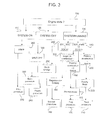
- figure 2 diagrammatically shows a diagram containing some operative functioning states of motor vehicle 3, indicated below as “engine operative states”, and the corresponding transition modes from one operative state to the other.
- the engine operative states which are relevant for understanding the present invention essentially comprise a SYSTEM RUNNING state (Cold Engine Management, Passive Boost, Regenerative Braking, Steady State, Quick Charge blocks), during which the internal combustion engine 2 is running; a SYSTEM-ON state (ENGINE OFF, AUTO SHUT OFF, CRANKING MANAGEMENT blocks), associated with a cranking condition, during which the internal combustion engine is transiting from an off condition to the SYSTEM RUNNING state; and a SYSTEM-OFF state (NP, OFF, SHUTOFF blocks), associated with a condition in which the internal combustion engine 2 is transiting from the SYSTEM RUNNING state to an off state.
- SYSTEM RUNNING state Cold Engine Management, Passive Boost, Regenerative Braking, Steady State, Quick Charge blocks
- the electronic control unit 18 is configured to determine the operative engine state (block 100) which, as mentioned above, may be a SYSTEM-ON state (block 110), a SYSTEM-OFF state (block 120) or a SYSTEM RUNNING state (block 130).
- the electronic control unit 18 is configured so as to implement a first regulation/control procedure/algorithm of alternator 4 (block 170) (described in detail below) when, during the SYSTEM RUNNING state, it determines a first operative state, indicated hereinafter as a PASSIVE BOOST state.
- the electronic control unit 18 is configured to determine the PASSIVE BOOST state (block 160) when, during the SYSTEM RUNNING state, the following conditions occur: the measured battery state of charge SOC_meas is either higher than or equal to a predetermined charge threshold SOClim (block 140); a first magnitude, indicating the acceleration Acc of the motor vehicle is positive and is either higher than or equal to a first acceleration threshold Acclim (block 150).
- the first magnitude may correspond to the acceleration Acc of the vehicle and/or to the mechanical torque generated by the internal combustion engine 2, and/or to the derivative of the mechanical torque generated by the engine 4 itself over time.
- the electronic control unit 18 is further configured to implement a second control algorithm/procedure of alternator 4 (block 180) (described in detail below) when, during the SYSTEM RUNNING state, it determines a second operative state, indicated below as a REGENERATIVE BRAKING state (block 190).
- the electronic control unit 18 determines the REGENERATIVE BRAKING state (block 190) when, during the SYSTEM RUNNING state, the following conditions occur: the measured battery charge state SOC_meas is either higher than or equal to a predetermined charge threshold SOClim (block 140); the first magnitude, indicating the acceleration of motor vehicle 3, is negative (block 200) and thus indicates that motor vehicle 3 is subjected to a deceleration caused, for example, by braking and/or by means of a cut-off of the motor vehicle 3 itself.
- the electronic control unit 18 is configured so as to implement a third control algorithm/procedure of alternator 4 (block 210) (described in detail below) when, during the SYSTEM RUNNING state, it determines a third operative state, indicated below as a STEADY STATE (block 220).
- the electronic control unit 18 determines the STEADY STATE when, during the SYSTEM RUNNING state, the measured battery state of charge SOC_meas 12 is higher than the predetermined charge threshold SOClim (block 140) and the first magnitude, indicating the acceleration of motor vehicle 3, is positive and lower than the first predetermined threshold (block 230).
- the electronic control unit 18 is configured so as to implement a fourth control algorithm/procedure of alternator 4 (block 240) (described in detail below) when it determines a fourth operative state, indicated hereinafter as a QUICK CHARGE state (block 250).
- a fourth control algorithm/procedure of alternator 4 block 240
- QUICK CHARGE state block 250
- the electronic control unit 18 determines the QUICK CHARGE state when, during the SYSTEM RUNNING state, the state of measured charge SOC_meas of the electric battery 6 is lower than the predetermined charge threshold SOClim (block 260).
- the electronic control unit 18 is configured so as to implement a fifth control algorithm/procedure of alternator 4 (block 270) (described in detail below) when, during the SYSTEM-ON state, it determines a fifth operative state, indicated hereinafter as a CRANK state (block 280).
- the electronic control unit 18 determines the CRANK state when the internal combustion engine 2 is in the cranking state.
- the electronic control unit 18 is configured so as to implement a sixth control algorithm/procedure of alternator 4 (block 290) (described in detail below) when, during the SYSTEM-OFF state, it determines a sixth operative state, indicated hereinafter as a SHUTOFF/AUTOSHUTOFF state (block 300).
- the electronic control unit 18 determines the SHUTOFF/AUTOSHUTOFF state when the internal combustion engine 2 is shut off by a manual control or by an automatic control, respectively.
- the first control procedure/algorithm of alternator 4 implemented by the electronic control unit 18 essentially comprises the steps of: determining an objective voltage V obj calculating an error signal V err indicating the difference between objective voltage V obj and measured battery voltage V bat_meas , determining the regulation voltage V reg by means of an open-loop regulation system/circuit 26 according to the error signal V err and to the objective voltage V obj .
- the objective voltage V obj is calculated according to the main electric supply range ⁇ Vlimit(VMIN P , VMAX P ), to the battery current I bat_meas , and to an on/off state of electric vehicle appliances 25 rotationally fed by the internal combustion engine 2.
- the first control procedure/algorithm of alternator 4 determines the objective voltage V obj by means of the following steps: calculating a voltage VECM lim related to the electronic vehicle appliances 25 rotationally fed by the internal combustion engine 2 itself which, for example, the engine cooling fan unit rotating at a predetermined speed, and/or the DPF (Diesel Particulate Filter) regeneration unit; and calculating a voltage V1(I bat ) related to the generation of a battery current I batt by the electric battery 6.
- a voltage VECM lim related to the electronic vehicle appliances 25 rotationally fed by the internal combustion engine 2 itself which, for example, the engine cooling fan unit rotating at a predetermined speed, and/or the DPF (Diesel Particulate Filter) regeneration unit
- V1(I bat ) related to the generation of a battery current I batt by the electric battery 6.
- Voltage VECM lim corresponds to a predetermined minimum value of the regulation voltage of alternator 4 so that the voltage generated by alternator 4 is sufficient to supply said active electronic vehicle appliances 25, while voltage V1(I bat ) substantially corresponds to a minimum, predetermined voltage value needed to prevent the electric battery 6 from discharging during the delivery of current I bat by the latter.
- the first control procedure/algorithm of alternator 4 calculates the objective voltage V obj thus determining the upper extreme, i.e. the maximum value between: the lower voltage VMIN P of the main electric supply range ⁇ Vlimit(VMIN P , VMAX P ), the voltage VECM lim and the voltage V1 (I bat_meas ).
- V obj MAX(VMIN P , VECM lim , V1 (I bat_meas ).
- the first control procedure/algorithm of alternator 4 determines the regulation voltage V reg by means of the open-loop regulation system/circuit 26 of the proportional-integral PI type described in detail below.
- the second control procedure/algorithm of alternator 4 essentially comprises the steps of: determining an objective voltage V obj , calculating an error signal V err indicating the difference between objective voltage V obj and measured battery voltage V bat_meas , determining the regulation voltage V reg by means of an open-loop regulation system/circuit 26 according to the error signal V err and to the objective voltage V obj .
- the objective voltage V obj is calculated according to the following parameters: the voltage VECM lim related to the actuation of the electronic vehicle appliances 25; the voltage V1(I bat_meas ) related to the battery current I batt_meas : the voltage V2(en_sp) related to the engine rpm en_sp.
- Voltage V2(en_sp) corresponds to a predetermined minimum value determined so as to limit the braking torque variation caused on the internal combustion engine by the electric frictions produced by the alternator, so as to advantageously ensure a gradual, i.e. not pulsing, transition of the engine itself from a normal operating condition to an idling operative condition, in which the rotation speed of the internal combustion engine 2 has a predetermined minimum value.
- the second control procedure/algorithm of alternator 4 calculates the objective voltage V obj determining the lower extreme, i.e. the minimum value between: the upper voltage VMIN P of the main electric supply range ⁇ Vlimit(VMIN P , VMAX P ), the voltage VECM lim , the voltage V1(I bat_meas ) and the voltage V2 (en_sp).
- V obj min (VMAX P , VECM lim , V1(I bat ), V2(I bat )).
- the second control procedure/algorithm of alternator 4 when motor vehicle 3 is in a deceleration state, thus controls the regulation voltage V reg of alternator 4 assigning the highest possible value thereto, compatibly with the limits/constrains determined by the main electric supply range, by the actuation of the vehicle appliances 25 and by the electric battery 6.
- the second control procedure/algorithm of alternator 4 determines the regulation voltage V reg by means of the regulation system/circuit 26 (either open-loop or closed-loop).
- the open-loop regulation system/circuit 26 used by the first and second control procedures/algorithms described above comprises a filtering block 27, an adder block 28, a proportional-integral block 29, an adder block 30, and a gradient limiting block 31.
- Filtering block 27 may preferably, but not necessarily, be a mobile average low-pass filter configured so as to: receive the input battery voltage V bat_meas , filter the battery voltage V bat_meas from the high frequencies so as to advantageously eliminate reading noises introduced by the intelligent battery state sensor 15, and to output the filtered battery voltage U bat_filt ⁇
- the adder block 28 is configured so as to: receive the input objective voltage V obj and the filtered battery voltage V bat_filt , output an error signal V err indicating the difference between the measured battery voltage V bat_meas and the objective voltage (V obj ).
- the proportional-integral block 29 is configured so as to multiply the error signal V err by a predetermined constant K1 and integrates the error signal multiplied by a second constant V err *K2 (not necessarily equal to K1) over time.
- the adder block 30 is configured to receive an input error signal V err output by the proportional-integral block 29 and the objective voltage V obj , and output a compensated target value V obj ' corresponding to the sum V err and objective voltage V obj .
- the gradient limiting block 31 is configured so as to: receive the compensated input objective voltage V obj ', limit the derivative of the compensated objective voltage V obj ' over time (preferably a discrete derivative) so as to keep it within a predetermined maximum-minimum range, and output the regulation voltage V reg of alternator 4.
- the open-loop contribution further ensures a more gradual control of the regulation voltage V reg , which will approach the objective V obj without producing under/over-shunting, nor non-zero errors when running, while the closed-loop contribution ensures a recovery of possible charge dispersions in the electric system consisting of alternator 4 and electric battery 6.
- the third control procedure/algorithm of alternator 4 provides for the electronic control unit 18 to regulate the voltage V reg so as to keep an optimal SOC, in addition to the above-described conditions.
- the third control procedure/algorithm of alternator 4 comprises the step of determining the regulation voltage V reg according to a difference ⁇ SOC between the objective stage of charge SOC_ obj of the electric battery 6 and the measured state of charge SOC _meas thereof and by means of a closed-loop control system/circuit 32.
- the electronic control unit 18 is configured to determine the objective state of charge SOC obj according to a series of data indicating the following parameters: the engine speed en_sp, the motor vehicle speed vn_sp, the torque load_v of the internal combustion engine 2 and the ambient temperature tes external to the electric battery.
- the closed-loop control system/circuit 32 used by the electronic control unit 18 during the implementation of the third control procedure/algorithm of alternator 4 comprises: an adder block 35, a regulation block 37, a compensator block 36, an adder block 38 and a calculation block 39.
- the adder block 35 is configured so as to receive the input objective state of charge SOC obj and the measured state of charge SOC meas and output a signal indicating the difference of charge ⁇ SOC between the two states.
- the regulator block 37 is configured so as to calculate an objective current I obj according to the difference of charge ⁇ SOC, by means of a function I obj ( ⁇ SOC) displaying a substantially discontinuous linear pattern provided with segments having mutually different angular coefficients.
- the function I obj comprises a first linear segment I obj1 ( ⁇ SOC) comprised between - ⁇ SOC 1 and ⁇ SOC 1 and displaying a minimum angular coefficient m1, approximately equal to zero, a second segment I obj2 ( ⁇ SOC) comprised between - ⁇ SOC 1 and - ⁇ SOC 2 and between ⁇ SOC 1 and ⁇ SOC 2 , having an angular coefficient m2 higher than the coefficient m1, and a third segment I obj3 ( ⁇ SOC) associated with the charge values ⁇ SOC lower than - ⁇ SOC 2 and higher than ⁇ SOC 2 , having an angular coefficient m3 substantially equal to zero.
- the difference of charge ⁇ SOC 1 may be preferably equal to approximately 2% of the nominal SOC of the electric battery 6, while the third segment I obj3 ( ⁇ SOC) may correspond to a current objective equal for example to approximately 75% of the maximum currently which may be delivered by alternator 4.
- the compensator block 36 is configured so as to receive the input difference of charge ⁇ SOC and the objective current I obj and outputs a compensation factor ICS of the objective current I obj itself.
- the compensator block 36 is activated when the following condition occurs: the absolute value of the objective current
- the compensator block 36 is configured so as to determine the compensation factor ICS dimensioned to compensate for the dissipations of current along the measuring chain which may induce a running error of the difference of charge ⁇ SOC.
- is equal to approximately 0.1V
- is equal to approximately 0.2V
- 2 A
- the fourth control procedure/algorithm of alternator 4 provides for the electronic control unit 18 to regulate the regulation voltage V reg of alternator 4 to the highest voltage level possible when SOC is too low.
- the fourth control procedure/algorithm of alternator 4 comprises the step of generating a predetermined regulation voltage V reg_QUICK having value equal, for example, to 95% of a nominal battery voltage U bat_nom .
- the fifth control procedure/algorithm of alternator 4 instead, provides for the electronic control unit 18 when cranking and according to the engine rpm en_sp to define two sub-steps of cranking in which the regulation voltage V reg is kept low at first, to facilitate the increase of rpm, and is then kept high to reduce the rpm overshoot after cranking.
- the fifth control procedure/algorithm of alternator 4 comprises the step of generating a first minimum predetermined regulation voltage V1 reg_crank , when during cranking, the rpm en_sp is lower than a predetermined threshold EN1, and a second predetermined maximum regulation voltage V2 reg_crank , when during cranking, the engine rpm en_sp is either higher or lower than the threshold EN1.
- the sixth control procedure/algorithm of alternator 4 instead comprises the step of generating a predetermined regulation voltage V reg_CAL having a calibratable value comprised between 13.5 V and 14.5 V.
- the electronic control unit 18 may further be configured to implement the third control procedure/algorithm of alternator 4 at predetermined intervals of time following a SOC obj equal, for example, to 95%, so as to run a "Battery Regeneration" cycle, thus advantageously reducing the so-called “memory effect” and ensuring a longer life to the electric battery.
- the "Battery Regeneration" cycle is configured to fully recharge the battery at predetermined intervals of time, such as for example one or two months.
- the present invention reduces electric friction and therefore the resistive torque caused by the alternator on the internal combustion engine of the motor vehicle determining, on one hand, a decrease of wastes of energy and, on the other hand, improves performance of the engine itself.
- the present invention further allows to dynamically estimate the contribution of electric loads of the alternator on the internal combustion engine so as to control the mechanical torque generated by the motor vehicle engine. Indeed, both the friction contribution caused by the alternator (in the duty cycle function of IAM) and the idling objective (according to battery SOC) may be dynamically estimated to improve handling in all engine conditions.
- the present invention further allows to advantageously increase the average battery life and to reduce internal combustion engine consumption and emissions.
- the studies carried out by the Applicant demonstrated that the reduction of consumption deriving from the above-described control system is of the order of 2-3% on the NEDC cycle.
- the present invention further allows to advantageously obtain an optimal adaptation to the various engine configurations.
- the same algorithm structure may be applied to any type of internal combustion engine provided with IAM+LIN+IBS architecture, regardless of the engine/transmission coupling, on both aspirated and turbocharged engines, for all types of fuel.
Abstract
Description
- The present invention relates to an automotive electrical system provided with an alternator electronic control system coupled to an internal combustion engine of a motor vehicle.
- As is known the alternator is a vehicle electrical device which is rotated by the internal combustion engine, and therefore affects the overall consumptions and emissions of the engine itself in a non-negligible manner.
- Automakers are gradually introducing alternator electronic control systems on motor vehicles in order to reduce fuel consumption and polluting emissions of the motor vehicles in urban traffic.
- The currently known alternator electronic control systems essentially calculate an efficiency index according to the working point of the internal combustion engine, and are configured so as to control the revolution speed of the alternator rotor and/or to vary the energizing/field current thereof according to the calculated efficiency index.
- However, the calculation of the efficiency index in the above-described electronic control systems is always rather complex and approximate, as the working point of the internal combustion engine is indirectly related to the current required from the alternator, which - as known - varies both according to the electric vehicle loads to be supplied, which are difficult to be predicted in advance, and to the voltage present at the ends of the terminals of the vehicle battery.
- In addition to the above description, the alternator control by the known electronic control systems described above is limited to the torque pattern of the internal combustion engine, but does not consider the state of charge of the battery, which is thus subject to progressively discharging over time.
- The Applicant has conducted an in-depth study aiming at founding a solution which specifically allows to achieve the following objectives:
- reducing the electric friction, and therefore the resistive torque caused by the alternator on the internal combustion engine of the motor vehicle, so as to reduce the energy wastes and improve the performance of the engine itself;
- dynamically estimating the contribution of the electric loads of the alternator on the internal combustion engine so as to control the mechanical torque generated by the motor vehicle engine with greater accuracy;
- increasing the average battery life;
- reducing internal combustion engine consumptions and emissions.
- It is thus the object of the present invention to provide a solution which allows to achieve the above-mentioned objectives.
- This object is achieved by the present invention as it relates to an alternator electronic control system, as defined in the appended claims.
-
-
Figure 1 is a block diagram of an vehicle electrical system for a motor vehicle made according to the dictates of the present invention; -
figure 2 is a state machine indicating the states of the motor vehicle engine shown infigure 1 ; -
figure 3 is a flow chart containing the operations implemented by the alternator electronic control system according to the dictates of the present invention; -
figure 4 is a block diagram of a first regulation procedure implemented by the alternator electronic control system shown infigure 1 ; -
figure 5 is a block diagram of a second regulation procedure implemented by the alternator electronic control system shown infigure 1 ; -
figure 6 is a block diagram of a third regulation procedure implemented by the alternator electronic control system shown infigure 1 ; while -
figure 7 is a block diagram of fourth, fifth and sixth regulation procedures implemented by the alternator electronic control system shown infigure 1 . - The present invention will now be described in detail with reference to the accompanying figures to allow a person skilled in the art to implement it and use it. Various changes to the described embodiments will be immediately apparent to people skilled in the art, and the described general principles may be applied to other embodiments and applications without therefore departing from the scope of protection of the present invention, as defined in the appended claims. Therefore, the present invention should not be considered as limited to the described and illustrated embodiments but instead the broadest scope of protection, in accordance with the principles and features described and claimed herein, is to be granted thereto.
- By way of non-limitative example,
figure 1 shows a block diagram of an automotiveelectrical system 1 comprising aninternal combustion engine 2 of a motor vehicle 3 (diagrammatically shown). - The automotive
electrical system 1 comprises an alternator 4, which is coupled to aninternal combustion engine 2 by means of amotion transmission member 5 adapted to rotate the rotor of alternator 4 so as to output an electric supply voltage/current Vsupply/Isupply. - Alternator 4 is of known type and will not be further described, except for specifying that it comprises an inductive electric circuit (not shown), which is adapted to be crossed by an electric control current Ireg adapted to regulate the supply voltage Vsup generated by the alternator 4 itself.
-
Motor vehicle 3 further comprises an electric battery 6 electrically connected to alternator 4 through an vehicleelectrical system 7, and a series of vehicleelectrical loads 8, which are electrically connected to alternator 4 and to electric battery 6 by means of theelectric vehicle system 7. - The vehicle
electrical loads 8 may comprise, for example, the electric system of the headlight system and/or the electric system of the wiper system and/or the electric system of the heated rear window system or any other type of similar electric/electronic device/apparatus which may be supplied by the alternator 4 present inmotor vehicle 3. - The automotive
electrical system 1 further comprises an alternator electronic control system 9 configured to vary said control current so as to regulate said supply voltage Vsup. - The alternator electronic control system 9 essentially comprises an Intelligent State Battery sensor 15 (IBS), a
body computer 16, anelectronic control unit 18, and an Intelligent Alternator Module 19 (IAM). - The Intelligent State
Battery sensor 15 is electrically coupled to the electric battery 6 to monitor, instant by instant, the operating state, and is configured so as to measure and output a series of battery state parameters pam_bat. - In the example shown in
Figure 1 , the measured battery state parameters pam_bat comprise: the internal battery temperature tbat_meas, the battery state of charge SOC_meas, the battery voltage Vbat_meas, and the battery current Ibat_meas. - The alternator electronic control system 9 further comprises a
data communication line 20 connecting the Intelligent Battery Statesensor 15 to thebody computer 16. The IntelligentState Battery sensor 15 may be configured to communicate the battery state parameters pam-bat (tbat_meas, SOC_meas, Vbat_meas, Ibat_meas) to thebody computer 16 over thedata communication line 20. Thedata communication line 20 may be preferably, but not necessarily, made by means of a data/control bus implementing a LIN (Local Interconnect Network) protocol. -
Body computer 16 determines the ON/OFF state of each of the vehicleelectrical loads 8 connected to alternator 4, and is configured to determine, for each of the vehicleelectrical loads 8 in the ON state, a supply constraint defined by an electric supply range, which is associated with an electric supply magnitude preferably corresponding to a voltage or electric current. The electric supply range is delimited above and below by maximum and minimum values of the electric magnitude, respectively, i.e. of the voltage or current. -
Body computer 16 may be configured to determine the electric supply range of each vehicleelectrical loads 8 according to the battery state parameters pam_bat. - For this purpose,
body computer 16 may be provided with an internal memory (not shown) containing one or more predetermined operating maps of the vehicleelectrical loads 8 associated with the supply constraints of the latter. Each operating map is capable of providing the electric supply range, i.e. the maximum and minimum voltage/current values to be supplied to the corresponding vehicleelectrical load 8 as the battery state parameters pam_bat vary. - Each operating map comprises, for each state/battery parameter or for each group of state/battery parameters, a corresponding electric supply range delimited above by a maximum acceptable value and below by a minimum acceptable voltage/current value which may be supplied to the vehicle
electrical load 8. - In the following example, for description simplicity but without loosing in generality, an electric supply range delimited by maximum and minimum supply voltage values, indicated with ΔV (Vmini, Vmaxi) will be considered, where Vmini is the minimum supply voltage, while Vmaxi is the maximum supply voltage of the i-th vehicle
electrical load 8. -
Body computer 16 is further configured to determine a main constraint, i.e. a main electric supply range ΔVlimit(VMINP,VMAXP) according to the maximum/minimum voltages Vmaxi,Vmini which delimit the electric supply ranges ΔV(Vmini,Vmaxi) of the single vehicleelectrical loads 8 on the ON states. For this purpose,body computer 16 may determine the main maximum voltage VMAXP and the main minimum voltage VMINP assigning the maximum and minimum voltage values, respectively, present in the electric supply ranges ΔV(Vmini,Vmaxi) of the vehicleelectrical loads 8. -
Body computer 16 is further able to receive diagnostic input data of alternator 4 and to communicate them to avehicle dashboard 21 over adata communication line 22, so as to signal a malfunctioning condition of alternator 4, e.g. by means of an alternator warning light (not shown) present on thevehicle dashboard 21 itself. -
Body computer 16 is further configured to communicate with theelectronic control unit 18 over acommunication line 23 so as to provide theelectronic control unit 18 with the main power supply range ΔVlimit VMINP, VMAXP) and the battery state parameters pam_bat, and to receive the diagnostic data of alternator 4 therefrom. In the example shown, thecommunication line 23 preferably, but not necessarily, comprises one or more CAN buses. - The intelligent
alternator control module 19 is configured to receive a regulation voltage Vreg over adata communication line 24 from theelectronic control unit 18. In the example shown infigure 1 , thedata communication line 24 preferably, but not necessarily, comprises a LIN bus. - The intelligent
alternator control module 19 is electrically connected to alternator 4, is configured so as to diagnose the operating state of alternator 4, and communicates the alternator diagnostic data to theelectronic control unit 18 over thedata communication line 24. - The intelligent
alternator control module 19 is further configured so as to regulate the energizing/control current Ireg circulating through the inductive/field circuit of alternator 4 according to the regulation voltage Vreg so as to generate the supply voltage Vsupply. For example, the intelligentalternator control module 19 may preferably, but not necessarily, comprise a PWM type current regulator able of varying the duty cycle of the energizing/control current Ireg supplied to the inductive/field circuit of alternator 4 according to the regulation voltage Vreg. The intelligentalternator control module 19 may be configured to communicate the duty cycle indicating data of the energizing/control current Ireg of alternator 4 to theelectronic control unit 18. - This value may be used by the
electronic control unit 18 to determine the structural effectiveness limits of the different control configurations of the regulation voltage Vreg, for example, according to the working load of alternator 4, as well as to determine the calculation of the friction contribution caused by alternator 4. - The
electronic control unit 18 is configured to determine the regulation voltage Vreg to be supplied to the intelligentalternator control module 19 according to: a series of operative vehicle states (described in detail below), the main supply range ΔVlimit(VMINP,VMAXP) determined bybody computer 16, the battery state parameters par_bat, and a series of vehicle data. - The
electronic control unit 18 is configured to determine a series of engine operating parameters, indicated hereinafter as engine parameters, such as, for example, the engine rpm en_sp, the external temperature tes of the motor vehicle, the torque load_v and the motor vehicle speed vh_sp. For this purpose, the alternator electronic control system 9 may be provided with specific sensors adapted to measure/determine the engine rpm en_sp, the external temperature tes of the motor vehicle, the torque generated by the internal combustion engine load_v, and the speed of the motor vehicle vh_sp. - The
electronic control unit 18 is further configured to implement a series of alternator control procedures/algorithms of alternator 4 (described in detail below) according to a series of operative conditions/states of theinternal combustion engine 2 ofmotor vehicle 3. - By way of example,
figure 2 diagrammatically shows a diagram containing some operative functioning states ofmotor vehicle 3, indicated below as "engine operative states", and the corresponding transition modes from one operative state to the other. The engine operative states which are relevant for understanding the present invention essentially comprise a SYSTEM RUNNING state (Cold Engine Management, Passive Boost, Regenerative Braking, Steady State, Quick Charge blocks), during which theinternal combustion engine 2 is running; a SYSTEM-ON state (ENGINE OFF, AUTO SHUT OFF, CRANKING MANAGEMENT blocks), associated with a cranking condition, during which the internal combustion engine is transiting from an off condition to the SYSTEM RUNNING state; and a SYSTEM-OFF state (NP, OFF, SHUTOFF blocks), associated with a condition in which theinternal combustion engine 2 is transiting from the SYSTEM RUNNING state to an off state. - With reference to
figures 2 and3 , theelectronic control unit 18 is configured to determine the operative engine state (block 100) which, as mentioned above, may be a SYSTEM-ON state (block 110), a SYSTEM-OFF state (block 120) or a SYSTEM RUNNING state (block 130). - In particular, the
electronic control unit 18 is configured so as to implement a first regulation/control procedure/algorithm of alternator 4 (block 170) (described in detail below) when, during the SYSTEM RUNNING state, it determines a first operative state, indicated hereinafter as a PASSIVE BOOST state. - In particular, the
electronic control unit 18 is configured to determine the PASSIVE BOOST state (block 160) when, during the SYSTEM RUNNING state, the following conditions occur: the measured battery state of charge SOC_meas is either higher than or equal to a predetermined charge threshold SOClim (block 140); a first magnitude, indicating the acceleration Acc of the motor vehicle is positive and is either higher than or equal to a first acceleration threshold Acclim (block 150). For this purpose, the first magnitude may correspond to the acceleration Acc of the vehicle and/or to the mechanical torque generated by theinternal combustion engine 2, and/or to the derivative of the mechanical torque generated by the engine 4 itself over time. - In particular, the
electronic control unit 18 is further configured to implement a second control algorithm/procedure of alternator 4 (block 180) (described in detail below) when, during the SYSTEM RUNNING state, it determines a second operative state, indicated below as a REGENERATIVE BRAKING state (block 190). - With reference to
figure 3 , theelectronic control unit 18 determines the REGENERATIVE BRAKING state (block 190) when, during the SYSTEM RUNNING state, the following conditions occur: the measured battery charge state SOC_meas is either higher than or equal to a predetermined charge threshold SOClim (block 140); the first magnitude, indicating the acceleration ofmotor vehicle 3, is negative (block 200) and thus indicates thatmotor vehicle 3 is subjected to a deceleration caused, for example, by braking and/or by means of a cut-off of themotor vehicle 3 itself. - Furthermore, the
electronic control unit 18 is configured so as to implement a third control algorithm/procedure of alternator 4 (block 210) (described in detail below) when, during the SYSTEM RUNNING state, it determines a third operative state, indicated below as a STEADY STATE (block 220). - With reference to
figure 3 , theelectronic control unit 18 determines the STEADY STATE when, during the SYSTEM RUNNING state, the measured battery state of charge SOC_meas 12 is higher than the predetermined charge threshold SOClim (block 140) and the first magnitude, indicating the acceleration ofmotor vehicle 3, is positive and lower than the first predetermined threshold (block 230). - Furthermore, the
electronic control unit 18 is configured so as to implement a fourth control algorithm/procedure of alternator 4 (block 240) (described in detail below) when it determines a fourth operative state, indicated hereinafter as a QUICK CHARGE state (block 250). - In particular, the
electronic control unit 18 determines the QUICK CHARGE state when, during the SYSTEM RUNNING state, the state of measured charge SOC_meas of the electric battery 6 is lower than the predetermined charge threshold SOClim (block 260). - Furthermore, the
electronic control unit 18 is configured so as to implement a fifth control algorithm/procedure of alternator 4 (block 270) (described in detail below) when, during the SYSTEM-ON state, it determines a fifth operative state, indicated hereinafter as a CRANK state (block 280). Theelectronic control unit 18 determines the CRANK state when theinternal combustion engine 2 is in the cranking state. - Furthermore, the
electronic control unit 18 is configured so as to implement a sixth control algorithm/procedure of alternator 4 (block 290) (described in detail below) when, during the SYSTEM-OFF state, it determines a sixth operative state, indicated hereinafter as a SHUTOFF/AUTOSHUTOFF state (block 300). Theelectronic control unit 18 determines the SHUTOFF/AUTOSHUTOFF state when theinternal combustion engine 2 is shut off by a manual control or by an automatic control, respectively. - With reference to
figure 4 , the first control procedure/algorithm of alternator 4 implemented by theelectronic control unit 18 essentially comprises the steps of: determining an objective voltage Vobj calculating an error signal Verr indicating the difference between objective voltage Vobj and measured battery voltage Vbat_meas, determining the regulation voltage Vreg by means of an open-loop regulation system/circuit 26 according to the error signal Verr and to the objective voltage Vobj. - In particular, the objective voltage Vobj is calculated according to the main electric supply range ΔVlimit(VMINP, VMAXP), to the battery current Ibat_meas, and to an on/off state of
electric vehicle appliances 25 rotationally fed by theinternal combustion engine 2. - The first control procedure/algorithm of alternator 4 determines the objective voltage Vobj by means of the following steps: calculating a voltage VECMlim related to the
electronic vehicle appliances 25 rotationally fed by theinternal combustion engine 2 itself which, for example, the engine cooling fan unit rotating at a predetermined speed, and/or the DPF (Diesel Particulate Filter) regeneration unit; and calculating a voltage V1(Ibat) related to the generation of a battery current Ibatt by the electric battery 6. - Voltage VECMlim corresponds to a predetermined minimum value of the regulation voltage of alternator 4 so that the voltage generated by alternator 4 is sufficient to supply said active
electronic vehicle appliances 25, while voltage V1(Ibat) substantially corresponds to a minimum, predetermined voltage value needed to prevent the electric battery 6 from discharging during the delivery of current Ibat by the latter. - The first control procedure/algorithm of alternator 4 calculates the objective voltage Vobj thus determining the upper extreme, i.e. the maximum value between: the lower voltage VMINP of the main electric supply range ΔVlimit(VMINP, VMAXP), the voltage VECMlim and the voltage V1 (Ibat_meas). In detail, Vobj=MAX(VMINP, VECMlim, V1 (Ibat_meas).
- Upon the calculation of the objective voltage Vobj, the first control procedure/algorithm of alternator 4 determines the regulation voltage Vreg by means of the open-loop regulation system/
circuit 26 of the proportional-integral PI type described in detail below. - With reference to
figure 5 , the second control procedure/algorithm of alternator 4 essentially comprises the steps of: determining an objective voltage Vobj, calculating an error signal Verr indicating the difference between objective voltage Vobj and measured battery voltage Vbat_meas, determining the regulation voltage Vreg by means of an open-loop regulation system/circuit 26 according to the error signal Verr and to the objective voltage Vobj. - In particular, the objective voltage Vobj is calculated according to the following parameters: the voltage VECMlim related to the actuation of the
electronic vehicle appliances 25; the voltage V1(Ibat_meas) related to the battery current Ibatt_meas: the voltage V2(en_sp) related to the engine rpm en_sp. - Voltage V2(en_sp) corresponds to a predetermined minimum value determined so as to limit the braking torque variation caused on the internal combustion engine by the electric frictions produced by the alternator, so as to advantageously ensure a gradual, i.e. not pulsing, transition of the engine itself from a normal operating condition to an idling operative condition, in which the rotation speed of the
internal combustion engine 2 has a predetermined minimum value. - The second control procedure/algorithm of alternator 4 calculates the objective voltage Vobj determining the lower extreme, i.e. the minimum value between: the upper voltage VMINP of the main electric supply range ΔVlimit(VMINP, VMAXP), the voltage VECMlim, the voltage V1(Ibat_meas) and the voltage V2 (en_sp). In detail, Vobj=min (VMAXP, VECMlim, V1(Ibat), V2(Ibat)).
- The second control procedure/algorithm of alternator 4, when
motor vehicle 3 is in a deceleration state, thus controls the regulation voltage Vreg of alternator 4 assigning the highest possible value thereto, compatibly with the limits/constrains determined by the main electric supply range, by the actuation of thevehicle appliances 25 and by the electric battery 6. - Upon the calculation of the objective voltage Vobj, the second control procedure/algorithm of alternator 4 determines the regulation voltage Vreg by means of the regulation system/circuit 26 (either open-loop or closed-loop).
- From the above description, it is further worth noting that by assigning the "highest" possible value to the objective voltage Vobj related to the regulation voltage Vreg of alternator 4 by means of the second procedure/algorithm, a controlled increase of the electric friction exerted by alternator 4 on the
internal combustion engine 2 is thus determined, which allows to obtain, on one hand, a reduction of the torque delivered by theinternal combustion engine 2 during the step of decelerating and, on the other hand, ensures a delivery of voltage by alternator 4 which is sufficient to supply both thevehicle appliances 25 and the electric battery 6. - It is further worth noting that by assigning the "lowest" possible value to the objective voltage Vobj related to the regulation voltage Vreg of alternator 4 by means of the first procedure/algorithm, a controlled decrease of the electric friction exerted by alternator 4 on the
internal combustion engine 2 is thus advantageously determined, which allows to obtain, on one hand, an increase of the torque delivered by theinternal combustion engine 2 with a reduction of consumptions/emissions of the engine itself and, on the other hand, ensures a delivery of voltage by alternator 4 which is sufficient to supply both thevehicle appliances 25 and the electric battery 6. - With reference to the example shown in
figures 4 and5 , the open-loop regulation system/circuit 26 used by the first and second control procedures/algorithms described above comprises afiltering block 27, anadder block 28, a proportional-integral block 29, anadder block 30, and agradient limiting block 31. -
Filtering block 27 may preferably, but not necessarily, be a mobile average low-pass filter configured so as to: receive the input battery voltage Vbat_meas, filter the battery voltage Vbat_meas from the high frequencies so as to advantageously eliminate reading noises introduced by the intelligentbattery state sensor 15, and to output the filtered battery voltage Ubat_filt· - The
adder block 28 is configured so as to: receive the input objective voltage Vobj and the filtered battery voltage Vbat_filt, output an error signal Verr indicating the difference between the measured battery voltage Vbat_meas and the objective voltage (Vobj). - The proportional-
integral block 29 is configured so as to multiply the error signal Verr by a predetermined constant K1 and integrates the error signal multiplied by a second constant Verr *K2 (not necessarily equal to K1) over time. - The
adder block 30 is configured to receive an input error signal Verr output by the proportional-integral block 29 and the objective voltage Vobj, and output a compensated target value Vobj' corresponding to the sum Verr and objective voltage Vobj. - The
gradient limiting block 31 is configured so as to: receive the compensated input objective voltage Vobj', limit the derivative of the compensated objective voltage Vobj' over time (preferably a discrete derivative) so as to keep it within a predetermined maximum-minimum range, and output the regulation voltage Vreg of alternator 4. - The open-loop contribution further ensures a more gradual control of the regulation voltage Vreg, which will approach the objective Vobj without producing under/over-shunting, nor non-zero errors when running, while the closed-loop contribution ensures a recovery of possible charge dispersions in the electric system consisting of alternator 4 and electric battery 6.
- The third control procedure/algorithm of alternator 4 provides for the
electronic control unit 18 to regulate the voltage Vreg so as to keep an optimal SOC, in addition to the above-described conditions. The third control procedure/algorithm of alternator 4 comprises the step of determining the regulation voltage Vreg according to a difference ΔSOC between the objective stage of charge SOC_obj of the electric battery 6 and the measured state of charge SOC_meas thereof and by means of a closed-loop control system/circuit 32. - With reference to
figure 6 , theelectronic control unit 18 is configured to determine the objective state of charge SOCobj according to a series of data indicating the following parameters: the engine speed en_sp, the motor vehicle speed vn_sp, the torque load_v of theinternal combustion engine 2 and the ambient temperature tes external to the electric battery. - For this purpose, the
electronic control unit 18 may determine the objective state of charge SOCobj by means of the following function:
wherein K is a predetermined constant, f1(vn_sp) is a function which allows to determine a value indicating a state of charge as the vehicle speed varies; f2(en_sp) is a function which allows to determine a value indicating the state of charge of the battery as the engine speed varies; f3(load_v) is a function which allows to determine a value indicating the state of charge of the battery as the torque varies; f4(tes) is a function which allows to determine a value indicating a state of charge of the battery as the external temperature of the electric battery 6 varies. - The closed-loop control system/
circuit 32, shown infigure 6 , used by theelectronic control unit 18 during the implementation of the third control procedure/algorithm of alternator 4 comprises: anadder block 35, aregulation block 37, acompensator block 36, anadder block 38 and acalculation block 39. - The
adder block 35 is configured so as to receive the input objective state of charge SOCobj and the measured state of charge SOCmeas and output a signal indicating the difference of charge ΔSOC between the two states. - The
regulator block 37 is configured so as to calculate an objective current Iobj according to the difference of charge ΔSOC, by means of a function Iobj(ΔSOC) displaying a substantially discontinuous linear pattern provided with segments having mutually different angular coefficients. - With reference to the example shown in
figure 6 , the function Iobj comprises a first linear segment Iobj1(ΔSOC) comprised between -ΔSOC1 and ΔSOC1 and displaying a minimum angular coefficient m1, approximately equal to zero, a second segment Iobj2(ΔSOC) comprised between - ΔSOC1 and - ΔSOC2 and between ΔSOC1 and ΔSOC2, having an angular coefficient m2 higher than the coefficient m1, and a third segment Iobj3(ΔSOC) associated with the charge values ΔSOC lower than - ΔSOC2 and higher than ΔSOC2, having an angular coefficient m3 substantially equal to zero. The difference of charge ΔSOC1 may be preferably equal to approximately 2% of the nominal SOC of the electric battery 6, while the third segment Iobj3(ΔSOC) may correspond to a current objective equal for example to approximately 75% of the maximum currently which may be delivered by alternator 4. - The
compensator block 36 is configured so as to receive the input difference of charge ΔSOC and the objective current Iobj and outputs a compensation factor ICS of the objective current Iobj itself. Thecompensator block 36 is activated when the following condition occurs: the absolute value of the objective current |Iobj| is lower than a predetermined threshold max_drift related to possibly dissipations of current Iobj along the measuring chain, and the absolute value of the difference of charge |ΔSOC| is higher than a predetermined minimum error. - The
compensator block 36 is configured so as to determine the compensation factor ICS dimensioned to compensate for the dissipations of current along the measuring chain which may induce a running error of the difference of charge ΔSOC. - The
adder block 38 is configured so as to receive the measured input battery current Ibat_meas, the objective current Iobj, and the compensation factor ICS and determine the objective current difference ΔIobj in the following manner:
- The
calculation block 39 is configured so as to receive the objective current difference ΔIobj and output a variation of the voltage ΔVreg by means of a function ΔVreg=fg (ΔIobj). - In the example shown in
figure 6 , the function ΔVreg=fg(ΔIobj) is in a stepped function and includes a zero step ΔVreg=0 in the objective current variation range (-ΔIobj1,ΔIobj1), a first step ΔVreg=-VR1,VR1 in the objective current variation ranges (ΔIobj1,ΔIobj2) and (ΔIobj1, -ΔIobj2), respectively, and a second step ΔVreg=-VR2,VR2 wherein |VR2| > |VR1| in the objective current variation ranges (-ΔIobj1, -ΔIobj2) and (ΔIobj1, ΔIobj2), respectively. In the example shown, |VR1| is equal to approximately 0.1V, |VR2| is equal to approximately 0.2V, |ΔIobj1|=2 A, |ΔIobj2|=4 A. - With reference to
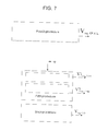
figure 7 , the fourth control procedure/algorithm of alternator 4 provides for theelectronic control unit 18 to regulate the regulation voltage Vreg of alternator 4 to the highest voltage level possible when SOC is too low. - The fourth control procedure/algorithm of alternator 4 comprises the step of generating a predetermined regulation voltage Vreg_QUICK having value equal, for example, to 95% of a nominal battery voltage Ubat_nom.
- The fifth control procedure/algorithm of alternator 4, instead, provides for the
electronic control unit 18 when cranking and according to the engine rpm en_sp to define two sub-steps of cranking in which the regulation voltage Vreg is kept low at first, to facilitate the increase of rpm, and is then kept high to reduce the rpm overshoot after cranking. - The fifth control procedure/algorithm of alternator 4 comprises the step of generating a first minimum predetermined regulation voltage V1reg_crank, when during cranking, the rpm en_sp is lower than a predetermined threshold EN1, and a second predetermined maximum regulation voltage V2reg_crank, when during cranking, the engine rpm en_sp is either higher or lower than the threshold EN1.
- The sixth control procedure/algorithm of alternator 4 instead comprises the step of generating a predetermined regulation voltage Vreg_CAL having a calibratable value comprised between 13.5 V and 14.5 V.
- The
electronic control unit 18 may further be configured to implement the third control procedure/algorithm of alternator 4 at predetermined intervals of time following a SOCobj equal, for example, to 95%, so as to run a "Battery Regeneration" cycle, thus advantageously reducing the so-called "memory effect" and ensuring a longer life to the electric battery. In particular, the "Battery Regeneration" cycle is configured to fully recharge the battery at predetermined intervals of time, such as for example one or two months. - The advantages that the present invention allows to obtain are apparent from the above description.
- The present invention reduces electric friction and therefore the resistive torque caused by the alternator on the internal combustion engine of the motor vehicle determining, on one hand, a decrease of wastes of energy and, on the other hand, improves performance of the engine itself.
- The present invention further allows to dynamically estimate the contribution of electric loads of the alternator on the internal combustion engine so as to control the mechanical torque generated by the motor vehicle engine. Indeed, both the friction contribution caused by the alternator (in the duty cycle function of IAM) and the idling objective (according to battery SOC) may be dynamically estimated to improve handling in all engine conditions.
- The present invention further allows to advantageously increase the average battery life and to reduce internal combustion engine consumption and emissions. In particular, the studies carried out by the Applicant demonstrated that the reduction of consumption deriving from the above-described control system is of the order of 2-3% on the NEDC cycle.
- The present invention further allows to advantageously obtain an optimal adaptation to the various engine configurations. Indeed, the same algorithm structure may be applied to any type of internal combustion engine provided with IAM+LIN+IBS architecture, regardless of the engine/transmission coupling, on both aspirated and turbocharged engines, for all types of fuel.
- It is finally apparent that changes and variations may be made to the above-disclosed description without departing from the scope of protection of the present invention, as defined in the appended claims.
Claims (22)
- Automotive electrical system (1) for a motor vehicle (3) comprising an internal combustion engine (2) of a motor vehicle (3); the automotive electrical system (1) comprising a number of electric vehicle loads (8), an electric battery (6), and an alternator (4) operable by the internal combustion engine (2) for generating a supply voltage (Vsup) adapted to be supplied to the electric vehicle loads (8) and to the electric battery (6); the alternator (4) comprising an inductive electric circuit adapted to be crossed, in use, by an electric control current (Ireg) adapted to regulate the supply voltage (Vsup); said automotive electrical system (1) comprising an alternator electronic control system (9) configured to vary said control current (Ireg) so as to regulate said supply voltage (Vsup); said automotive electrical system (1) being characterized in that said alternator electronic control system (9) is further configured to:- determine a series of battery parameters (pam_bat) indicating the operating state of the electric battery (6);- determine at least one first vehicle parameter (Acc) indicating the acceleration of the motor vehicle (3);- determine the operative state of the internal combustion engine (2);- determine an electric regulation voltage (Vreg) according to said operative state of the engine, to the vehicle parameter (Acc) and to said battery parameters (pam_bat);- vary the electric control current (Ireg) circulating, in use, in the inductive electric circuit of the alternator (4) according to said electric regulation voltage (Vreg).
- Automotive electrical system according to claim 1, wherein said alternator electronic control system (9) is configured so as to implement a first regulation procedure to reduce said electric regulation voltage (Vreg) when a first condition is determined, wherein:- the operative state of the internal combustion engine corresponds to an engine running state (SYSTEM RUNNING);- a battery parameter (pam_bat) indicating the battery state of charge (SOCmeas) is either higher than or equal to a predetermined charge threshold (SOClim); and- said first vehicle parameter (Acc) indicating the acceleration of the motor vehicle (3) is either higher than or equal to a first predetermined acceleration threshold (ACClim).
- Automotive electrical system according to claim 2, wherein the system is configured to implement a second regulation procedure adapted to increase said electric regulation voltage (Vreg) when a second condition is determined, wherein:- the operative state of the engine corresponds to an engine running state (SYSTEM RUNNING);- said battery parameter (pam_bat) indicating the battery state of charge (SOCmeas) is either higher than or equal to a predetermined charge threshold (SOClim); and- said first vehicle parameter (Acc) indicates a deceleration of the motor vehicle (3).
- Automotive electrical system according to claim 3, wherein said alternator electronic control system (9) is configured to implement a third procedure of regulating said electric regulation voltage (Vreg) when a third condition is determined, wherein:- the operative state of the internal combustion engine (2) corresponds to an engine running state (SYSTEM RUNNING);- a battery parameter (pam_bat) indicating the battery state of charge (SOCmeas) is either higher than or equal to a predetermined charge threshold (SOClim); and- said first vehicle parameter (Acc) indicating the acceleration of the motor vehicle (3) is positive and lower than said first predetermined threshold (ACClim).
- Automotive electrical system according to claim 4, wherein said system (9) is configured to implement a fourth regulation procedure adapted to assign a predetermined value to said electric regulation voltage (Vreg) when a fourth condition is determined, wherein:- the operative vehicle/engine state corresponds to an engine running state (SYSTEM RUNNING);- said battery parameter (pa_bat) indicating the battery state of charge (SOCmeas) is lower than a predetermined charge threshold (SOClim); and- said first vehicle parameter (Acc) indicating the acceleration of the motor vehicle (3) is positive and lower than said first predetermined threshold (ACClim).
- Automotive electrical system according to any one of the claims from 2 and 5, wherein said first control procedure is designed so that, when run, the electronic control system (9) is configured to:- determine on objective voltage (Vobj);- calculate an error signal (Verr) indicating the difference between the objective voltage (Vobj) and the measured battery voltage (Vbat_meas);- determine said regulation voltage (Vreg) by means of an open-loop regulation system/circuit (26) of proportional-integral type according to the error signal (Verr) and to the objective voltage (Vobj).
- Automotive electrical system according to claim 6, wherein said first control procedure is designed so that, when run, the electronic control system (9) is configured to:- calculate a main electric supply range (ΔVlimit(VMINP,VMAXP)) according to the maximum/minimum voltages (Vmaxi,Vmini) which delimit the electric power supply ranges (ΔV(Vmini,Vmaxi)) of the running vehicle electrical loads (8);- calculate a first voltage (VECMlim) related to the actuation of electronic vehicle appliances (25) rotated by said internal combustion engine (2);- calculate a second voltage (V1(Ibat)) related to a battery parameter (pam_bat) indicating the battery current (Ibat_meas);- calculate said objective voltage (Vobj) by determining the upper extreme between the lower voltage (VMINP) of said main electric supply range (OVlimit (VMINP, VMAXP)), said voltage (VECMlim) and said voltage (V1(Ibat_meas))·
- Automotive electrical system according to any one of the claims 6 or 7, wherein said second control procedure is designed so that, when run, the alternator electronic control system (9) is configured to:- calculate a main electric supply range (ΔVlimit(VMINP,VMAXP)) according to the maximum/minimum voltages (Vmaxi,Vmini) which delimit the electric power supply ranges (ΔV(Vmini,Vmaxi)) of the single running electric vehicle loads (8);- calculate a first voltage (VECMlim) related to the actuation of the electronic vehicle appliances (25);- calculate a second voltage (V1(Ibat_meas)) related to a battery parameter indicating the battery current (Ibat_meas);- calculate a third voltage (V2(en_sp)) related to a vehicle parameter indicating the revolution speed of the engine (en_sp);- calculate the objective voltage (Vobj) by determining the lower extreme between: the upper voltage (VMAXP) of the main electric supply range (ΔVlimit(VMINP, VMAXP)), the first voltage (VECMlim) , the sceond voltage (V1(Ibat_meas)) and the third voltage (V2(en_sp)).
- Automotive electrical system according to any one of the claims from 6 to 8, wherein said open-loop regulation system/circuit (26) of proportional-integral type is configured to:- receive the input objective voltage (Vobj) and a battery voltage (Vbat_meas) so as to output an error signal (Verr) indicating the difference between the measured battery voltage (Vbat_meas) and the objective voltage (Vobj);- integrate the error signal (Verr) multiplied by a constant (K1) so as to determine an integrated error signal (Verr) over time;- determine a compensated objective voltage (Vobj') by adding the integrated error signal (Verr) to the objective voltage (Vobj);- determine the regulation voltage (Vreg), by limiting the derivative of the compensated objective voltage (Vobj') within a predetermined maximum-minimum derivation range over time.
- Automotive electrical system according to any one of the claims from 4 and 9, wherein the third procedure is designed so that, when run, the alternator electronic control system (9) is configured to:- determine, by means of a closed-loop control system/circuit (32), the regulation voltage (Vreg) according to a difference (ΔSOC) between the objective charge state (SOC_obj) of the electric battery (6) and the measured state of charge (SOC_meas) thereof.
- Automotive electrical system according to claim 10, wherein the third procedure is designed so that, when run, the alternator electronic control system (9) is configured to determine the objective charge state (SOCobj) by means of the following function:

wherein: K is a predetermined constant,
f1(vn_sp) is a function which allows to determine a value indicating a state of charge of the electric battery (6) as the speed (vn_sp) of the motor vehicle (2) varies;
f2(en_sp) is a function which allows to determine a value indicating a state of charge of the battery as the engine speed (en_sp) varies;
f3(load_v) is a function which allows to determine a value indicating a state of charge of the battery as the torque (load_v) varies;
f4(tes) is a function which allows to determine a value indicating a state of charge of the battery (6) as the external temperature (tes) of the battery (6) varies. - Automotive electrical system according to claim 11, wherein said closed-loop control system/circuit (32) is configured so to:- receive the input objective state of charge (SOCobj) and the measured state of charge (SOCmeas) so as to output a signal indicating the charge difference (ΔSOC) between the two states;- calculate an objective current (Iobj) according to the charge difference (ΔSOC), by means of a function (Iobj(ΔSOC)) having a substantially linear, discontinuous pattern;- determine a compensation factor (ICS) of the objective current (Iobj) according to the charge difference (ΔSOC) and to the objective current (Iobj);- determine an objective current difference (ΔIobj) as follows:
 - determine a voltage variation (ΔVreg) by means of a predetermined stepped function (ΔVreg=fg (ΔIobj)) according to the objective current difference (ΔIobj);- determine the regulation voltage (Vreg) according to the calculated voltage variation (ΔVreg) and to the regulation voltage (Vreg_old) determined in a preceding calculation instant.
 - Automotive electrical system according to any one of the claims from 5 to 12, wherein said fourth regulation procedure is designed so that, when run, the alternator electronic control system (9) is configured to generate a predetermined regulation voltage (Vreg_QUICK) having a value from 90 to 100% of a nominal battery voltage (Vbat_nom)·
- Automotive electrical system according to any one of the preceding claims, wherein said alternator electronic control system (9) is configured to implement a fifth regulation procedure of the alternator 4 (block 270) when the internal combustion engine 2 is in the cranking step.
- Automotive electrical system according to any one of the preceding claims, wherein said fifth regulation procedure is designed so that, when run, the alternator electronic control system (9) is configured to:- determine a first predetermined minimum regulation voltage (V1reg_Crank) when, during cranking, the engine rpm (en_sp) is lower than a predetermined threshold (EN1);- determine a second predetermined maximum regulation voltage (V2reg_Crank), higher than the first predetermined minimum regulation voltage (V1reg_Crank) when, during cranking, the engine rpm (en_sp) is higher than the threshold (EN1).
- Automotive electrical system according to any one of the preceding claims, wherein said alternator electronic control system (9) is configured to implement a sixth regulation procedure of the regulation voltage (Vreg) when the internal combustion engine 2 is off.
- Automotive electrical system according to claim 16, wherein said sixth regulation procedure is designed so that, when run, the alternator electronic control system (9) is configured to generate a predetermined regulation voltage (Vreg_CAL) having a value which may be calibrated from 13.5 V to 14.5 V.
- Automotive electrical system according to claim 17, wherein said alternator electronic control system (9) is configured to implement said third regulation procedure at predetermined time intervals so as to obtain a high objective charge (SOCobj).
- A motor vehicle (2) comprising an automotive electrical system (1) according to any one of the preceding claims.
- An alternator electronic control system (9) for an automotive electrical system (1), as claimed in any one of the claims from 1 to 18.
- A vehicle electronic control unit (18) for an automotive electrical system (1), as claimed in any one of the claims from 1 to 18.
- A software loadable in a vehicle electronic control unit (18) and designed so that, when run, the vehicle electronic control unit (18) is configured as claimed in any one of the claims from 1 to 18.
Priority Applications (6)
| Application Number | Priority Date | Filing Date | Title |
|---|---|---|---|
| EP10425352A EP2453546A1 (en) | 2010-11-12 | 2010-11-12 | Automotive electrical system previded with an alternator electronic control system |
| CN201180054587.9A CN103299507B (en) | 2010-11-12 | 2011-11-12 | Automotive electrical system provided with an alternator electronic control system |
| JP2013538218A JP6053689B2 (en) | 2010-11-12 | 2011-11-12 | Automotive electrical system with alternator electronic control system |
| PCT/EP2011/069989 WO2012062926A2 (en) | 2010-11-12 | 2011-11-12 | Automotive electrical system provided with an alternator electronic control system |
| US13/884,245 US9168881B2 (en) | 2010-11-12 | 2011-11-12 | Automotive electrical system provided with an alternator electronic control system |
| EP11782420.1A EP2638614B1 (en) | 2010-11-12 | 2011-11-12 | Automotive electrical system provided with an alternator electronic control system |
Applications Claiming Priority (1)
| Application Number | Priority Date | Filing Date | Title |
|---|---|---|---|
| EP10425352A EP2453546A1 (en) | 2010-11-12 | 2010-11-12 | Automotive electrical system previded with an alternator electronic control system |
Publications (1)
| Publication Number | Publication Date |
|---|---|
| EP2453546A1 true EP2453546A1 (en) | 2012-05-16 |
Family
ID=44971015
Family Applications (2)
| Application Number | Title | Priority Date | Filing Date |
|---|---|---|---|
| EP10425352A Withdrawn EP2453546A1 (en) | 2010-11-12 | 2010-11-12 | Automotive electrical system previded with an alternator electronic control system |
| EP11782420.1A Active EP2638614B1 (en) | 2010-11-12 | 2011-11-12 | Automotive electrical system provided with an alternator electronic control system |
Family Applications After (1)
| Application Number | Title | Priority Date | Filing Date |
|---|---|---|---|
| EP11782420.1A Active EP2638614B1 (en) | 2010-11-12 | 2011-11-12 | Automotive electrical system provided with an alternator electronic control system |
Country Status (5)
| Country | Link |
|---|---|
| US (1) | US9168881B2 (en) |
| EP (2) | EP2453546A1 (en) |
| JP (1) | JP6053689B2 (en) |
| CN (1) | CN103299507B (en) |
| WO (1) | WO2012062926A2 (en) |
Cited By (4)
| Publication number | Priority date | Publication date | Assignee | Title |
|---|---|---|---|---|
| FR2992788A1 (en) * | 2012-06-28 | 2014-01-03 | Peugeot Citroen Automobiles Sa | Method for checking alternator-starter and e.g. stable battery, in car, involves determining setpoint representative of current that is to be circulated in electric power storage unit according to requested lifetime of vehicle |
| WO2014099526A3 (en) * | 2012-12-18 | 2014-08-14 | Chrysler Group Llc | Alternator control for battery charging |
| EP3549809A1 (en) * | 2018-04-03 | 2019-10-09 | Toyota Jidosha Kabushiki Kaisha | Charge-discharge control system for vehicle |
| US20220009612A1 (en) * | 2017-01-11 | 2022-01-13 | Brunswick Corporation | Pcm controlled charging system |
Families Citing this family (12)
| Publication number | Priority date | Publication date | Assignee | Title |
|---|---|---|---|---|
| EP2894485B1 (en) * | 2014-01-10 | 2019-10-16 | Volvo Car Corporation | Method for performing a diagnostic test of an alternator in a vehicle, test arrangement and vehicle |
| DE202014007059U1 (en) * | 2014-08-29 | 2015-12-04 | GM Global Technology Operations LLC (n. d. Ges. d. Staates Delaware) | internal combustion engine |
| FR3036865B1 (en) * | 2015-06-01 | 2017-07-07 | Peugeot Motocycles Sa | METHOD FOR CONTROLLING A BATTERY AND ALTERNATOR ASSEMBLY FOR A MOTOR VEHICLE ENGINE |
| CN107231013B (en) * | 2016-05-24 | 2019-01-15 | 华为技术有限公司 | A kind of method of charging, terminal, charger and system |
| KR101806179B1 (en) * | 2016-06-02 | 2017-12-07 | 현대자동차 주식회사 | Method for controlling torque reduction of hybrid vehicle |
| IT201600112523A1 (en) * | 2016-11-08 | 2018-05-08 | Magneti Marelli Spa | "Energy management apparatus supplied to a low voltage system of a motor vehicle comprising an energy recovery stage and relative process" |
| KR102419042B1 (en) | 2017-05-12 | 2022-07-11 | 현대자동차주식회사 | Learning algorithm for controlling the voltage of battery |
| CN107612110A (en) * | 2017-08-15 | 2018-01-19 | 北京奥博汽车电子电器有限公司 | A kind of generator storage battery administration system of intelligent automobile storage battery administration |
| DE102017222843A1 (en) * | 2017-12-15 | 2019-06-19 | Robert Bosch Gmbh | Method for operating a charge controller for an electrical store in a motor vehicle |
| IT201800002823A1 (en) | 2018-02-19 | 2019-08-19 | Fiat Ricerche | OPERATION MANAGEMENT OF A DOUBLE BATTERY AUTOMOTIVE ELECTRIC SYSTEM WITH KINETIC ENERGY RECOVERY DURING BRAKING |
| US11670952B2 (en) * | 2019-10-18 | 2023-06-06 | Fca Us Llc | Voltage estimation for automotive battery charging system control |
| CN111817419A (en) * | 2020-08-11 | 2020-10-23 | 浙江三一装备有限公司 | Intelligent power management system and power management method of crawler crane |
Citations (4)
| Publication number | Priority date | Publication date | Assignee | Title |
|---|---|---|---|---|
| US4651081A (en) * | 1985-02-25 | 1987-03-17 | Mitsubishi Denki Kabushiki Kaisha | Control apparatus for vehicular charging generator |
| EP0735641A1 (en) * | 1995-03-31 | 1996-10-02 | Mitsubishi Denki Kabushiki Kaisha | Charge control system for use in internal combustion engine |
| US5608309A (en) * | 1993-02-24 | 1997-03-04 | Hitachi, Ltd. | Vehicle-use alternating current generator control system |
| US20040174018A1 (en) * | 2003-03-06 | 2004-09-09 | Yasumitsu Itoh | Power generation controller for AC generator |
Family Cites Families (10)
| Publication number | Priority date | Publication date | Assignee | Title |
|---|---|---|---|---|
| JP3286492B2 (en) * | 1995-04-28 | 2002-05-27 | 本田技研工業株式会社 | Control device for on-board power generator |
| JP2006304574A (en) * | 2005-04-25 | 2006-11-02 | Toyota Motor Corp | Power supply and its control method |
| JP4622838B2 (en) * | 2005-12-09 | 2011-02-02 | マツダ株式会社 | Automotive engine control system |
| JP2008279980A (en) * | 2007-05-14 | 2008-11-20 | Toyota Motor Corp | Power supply control device for vehicle |
| JP4973639B2 (en) * | 2007-12-11 | 2012-07-11 | 株式会社デンソー | Charge control device and charge control system |
| JP5217430B2 (en) * | 2007-12-28 | 2013-06-19 | トヨタ自動車株式会社 | Alternator control device and alternator control method |
| JP5351904B2 (en) * | 2008-01-22 | 2013-11-27 | 本田技研工業株式会社 | System and method for controlling an electrical system of a vehicle |
| JP5391598B2 (en) * | 2008-07-10 | 2014-01-15 | 株式会社明電舎 | Stabilized control system for distributed power supply |
| JP2010025055A (en) * | 2008-07-23 | 2010-02-04 | Mitsubishi Motors Corp | Alternator control device |
| JP2010259152A (en) * | 2009-04-21 | 2010-11-11 | Toyota Motor Corp | Device for control of power generation |
-
2010
- 2010-11-12 EP EP10425352A patent/EP2453546A1/en not_active Withdrawn
-
2011
- 2011-11-12 WO PCT/EP2011/069989 patent/WO2012062926A2/en active Application Filing
- 2011-11-12 JP JP2013538218A patent/JP6053689B2/en active Active
- 2011-11-12 US US13/884,245 patent/US9168881B2/en active Active
- 2011-11-12 CN CN201180054587.9A patent/CN103299507B/en active Active
- 2011-11-12 EP EP11782420.1A patent/EP2638614B1/en active Active
Patent Citations (4)
| Publication number | Priority date | Publication date | Assignee | Title |
|---|---|---|---|---|
| US4651081A (en) * | 1985-02-25 | 1987-03-17 | Mitsubishi Denki Kabushiki Kaisha | Control apparatus for vehicular charging generator |
| US5608309A (en) * | 1993-02-24 | 1997-03-04 | Hitachi, Ltd. | Vehicle-use alternating current generator control system |
| EP0735641A1 (en) * | 1995-03-31 | 1996-10-02 | Mitsubishi Denki Kabushiki Kaisha | Charge control system for use in internal combustion engine |
| US20040174018A1 (en) * | 2003-03-06 | 2004-09-09 | Yasumitsu Itoh | Power generation controller for AC generator |
Cited By (9)
| Publication number | Priority date | Publication date | Assignee | Title |
|---|---|---|---|---|
| FR2992788A1 (en) * | 2012-06-28 | 2014-01-03 | Peugeot Citroen Automobiles Sa | Method for checking alternator-starter and e.g. stable battery, in car, involves determining setpoint representative of current that is to be circulated in electric power storage unit according to requested lifetime of vehicle |
| WO2014099526A3 (en) * | 2012-12-18 | 2014-08-14 | Chrysler Group Llc | Alternator control for battery charging |
| US9083202B2 (en) | 2012-12-18 | 2015-07-14 | Fca Us Llc | Alternator control for battery charging |
| US20220009612A1 (en) * | 2017-01-11 | 2022-01-13 | Brunswick Corporation | Pcm controlled charging system |
| US11897591B2 (en) * | 2017-01-11 | 2024-02-13 | Brunswick Corporation | PCM controlled charging system |
| EP3549809A1 (en) * | 2018-04-03 | 2019-10-09 | Toyota Jidosha Kabushiki Kaisha | Charge-discharge control system for vehicle |
| CN110350612A (en) * | 2018-04-03 | 2019-10-18 | 丰田自动车株式会社 | The charge-discharge controller of vehicle |
| EP3549809B1 (en) * | 2018-04-03 | 2021-07-28 | Toyota Jidosha Kabushiki Kaisha | Charge-discharge control system for vehicle |
| US11221369B2 (en) | 2018-04-03 | 2022-01-11 | Toyota Jidosha Kabushiki Kaisha | Charge-discharge control system for vehicle |
Also Published As
| Publication number | Publication date |
|---|---|
| WO2012062926A3 (en) | 2013-01-10 |
| CN103299507A (en) | 2013-09-11 |
| WO2012062926A2 (en) | 2012-05-18 |
| US9168881B2 (en) | 2015-10-27 |
| CN103299507B (en) | 2015-07-15 |
| EP2638614B1 (en) | 2014-07-02 |
| JP2013542132A (en) | 2013-11-21 |
| US20130313897A1 (en) | 2013-11-28 |
| EP2638614A2 (en) | 2013-09-18 |
| JP6053689B2 (en) | 2016-12-27 |
Similar Documents
| Publication | Publication Date | Title |
|---|---|---|
| EP2638614B1 (en) | Automotive electrical system provided with an alternator electronic control system | |
| US7917276B2 (en) | Vehicle-use power supply apparatus | |
| US7107956B2 (en) | Vehicle and method for controlling engine start in a vehicle | |
| US7797089B2 (en) | System and method for managing a power source in a vehicle | |
| CN102398589B (en) | Output torque management in a vehicle having an electric powertrain | |
| US20120181854A1 (en) | Method and apparatus for electric power management in a vehicle | |
| US20060113799A1 (en) | Exhaust gas-driven generator system and method of controlling electrical system | |
| US20140214268A1 (en) | Temperature compensated battery parameter estimation | |
| CN104044478A (en) | Selective Updating Of Battery Parameter Estimations | |
| US20150251543A1 (en) | Vehicle controlling system | |
| US10836276B2 (en) | Display device | |
| US7335131B2 (en) | Vehicle and method for controlling an engine in a vehicle | |
| KR101558359B1 (en) | Method for monitoring torque in hybrid elecric vehicle | |
| US11827209B2 (en) | Motor control device | |
| RU2557686C1 (en) | Coordinated control over hybrid vehicle electromechanical transmission | |
| US8847558B2 (en) | Method and device for operating a generator in a recuperation system of a motor vehicle | |
| KR102221400B1 (en) | Mild hybrid vehicle and MHSG Torque limiting method of Mild hybrid vehicle | |
| CN106541939B (en) | Oil retention strategy for electric vehicles | |
| CN111479735B (en) | Vehicle control method and vehicle control device | |
| US20140379186A1 (en) | Electronic control device | |
| KR100901565B1 (en) | Apparatus for controling alternater of automobile | |
| CN115891968B (en) | Direct-drive power-supplementing control method, device and equipment for hybrid electric vehicle and medium | |
| US20220314960A1 (en) | Method for managing a torque to be supplied by an electric motor | |
| CN109291868B (en) | Hybrid vehicle type power generation control method and system | |
| KR20030089895A (en) | Interface apparatus of on hybrid electric vehicle |
Legal Events
| Date | Code | Title | Description |
|---|---|---|---|
| PUAI | Public reference made under article 153(3) epc to a published international application that has entered the european phase |
Free format text: ORIGINAL CODE: 0009012 |
|
| AK | Designated contracting states |
Kind code of ref document: A1 Designated state(s): AL AT BE BG CH CY CZ DE DK EE ES FI FR GB GR HR HU IE IS IT LI LT LU LV MC MK MT NL NO PL PT RO RS SE SI SK SM TR |
|
| AX | Request for extension of the european patent |
Extension state: BA ME |
|
| RIN1 | Information on inventor provided before grant (corrected) |
Inventor name: VENNETTILLI, NANDO Inventor name: GAROFALO, FABIO Inventor name: TAVELLA, DOMENICO Inventor name: RIEGEL, ALESSANDRO Inventor name: SANAPO, ANGELO |
|
| STAA | Information on the status of an ep patent application or granted ep patent |
Free format text: STATUS: THE APPLICATION IS DEEMED TO BE WITHDRAWN |
|
| 18D | Application deemed to be withdrawn |
Effective date: 20121117 |