EP2452901A1 - Heat-resistant laminated conveyor belt - Google Patents
Heat-resistant laminated conveyor belt Download PDFInfo
- Publication number
- EP2452901A1 EP2452901A1 EP10797159A EP10797159A EP2452901A1 EP 2452901 A1 EP2452901 A1 EP 2452901A1 EP 10797159 A EP10797159 A EP 10797159A EP 10797159 A EP10797159 A EP 10797159A EP 2452901 A1 EP2452901 A1 EP 2452901A1
- Authority
- EP
- European Patent Office
- Prior art keywords
- heat
- core
- conveyer belt
- resistant laminated
- woven fabric
- Prior art date
- Legal status (The legal status is an assumption and is not a legal conclusion. Google has not performed a legal analysis and makes no representation as to the accuracy of the status listed.)
- Granted
Links
Images


Classifications
-
- B—PERFORMING OPERATIONS; TRANSPORTING
- B65—CONVEYING; PACKING; STORING; HANDLING THIN OR FILAMENTARY MATERIAL
- B65G—TRANSPORT OR STORAGE DEVICES, e.g. CONVEYORS FOR LOADING OR TIPPING, SHOP CONVEYOR SYSTEMS OR PNEUMATIC TUBE CONVEYORS
- B65G15/00—Conveyors having endless load-conveying surfaces, i.e. belts and like continuous members, to which tractive effort is transmitted by means other than endless driving elements of similar configuration
- B65G15/30—Belts or like endless load-carriers
-
- B—PERFORMING OPERATIONS; TRANSPORTING
- B65—CONVEYING; PACKING; STORING; HANDLING THIN OR FILAMENTARY MATERIAL
- B65G—TRANSPORT OR STORAGE DEVICES, e.g. CONVEYORS FOR LOADING OR TIPPING, SHOP CONVEYOR SYSTEMS OR PNEUMATIC TUBE CONVEYORS
- B65G15/00—Conveyors having endless load-conveying surfaces, i.e. belts and like continuous members, to which tractive effort is transmitted by means other than endless driving elements of similar configuration
- B65G15/30—Belts or like endless load-carriers
- B65G15/32—Belts or like endless load-carriers made of rubber or plastics
-
- B—PERFORMING OPERATIONS; TRANSPORTING
- B29—WORKING OF PLASTICS; WORKING OF SUBSTANCES IN A PLASTIC STATE IN GENERAL
- B29C—SHAPING OR JOINING OF PLASTICS; SHAPING OF MATERIAL IN A PLASTIC STATE, NOT OTHERWISE PROVIDED FOR; AFTER-TREATMENT OF THE SHAPED PRODUCTS, e.g. REPAIRING
- B29C43/00—Compression moulding, i.e. applying external pressure to flow the moulding material; Apparatus therefor
- B29C43/02—Compression moulding, i.e. applying external pressure to flow the moulding material; Apparatus therefor of articles of definite length, i.e. discrete articles
- B29C43/20—Making multilayered or multicoloured articles
- B29C43/203—Making multilayered articles
-
- B—PERFORMING OPERATIONS; TRANSPORTING
- B65—CONVEYING; PACKING; STORING; HANDLING THIN OR FILAMENTARY MATERIAL
- B65G—TRANSPORT OR STORAGE DEVICES, e.g. CONVEYORS FOR LOADING OR TIPPING, SHOP CONVEYOR SYSTEMS OR PNEUMATIC TUBE CONVEYORS
- B65G15/00—Conveyors having endless load-conveying surfaces, i.e. belts and like continuous members, to which tractive effort is transmitted by means other than endless driving elements of similar configuration
- B65G15/30—Belts or like endless load-carriers
- B65G15/32—Belts or like endless load-carriers made of rubber or plastics
- B65G15/34—Belts or like endless load-carriers made of rubber or plastics with reinforcing layers, e.g. of fabric
-
- B—PERFORMING OPERATIONS; TRANSPORTING
- B65—CONVEYING; PACKING; STORING; HANDLING THIN OR FILAMENTARY MATERIAL
- B65G—TRANSPORT OR STORAGE DEVICES, e.g. CONVEYORS FOR LOADING OR TIPPING, SHOP CONVEYOR SYSTEMS OR PNEUMATIC TUBE CONVEYORS
- B65G15/00—Conveyors having endless load-conveying surfaces, i.e. belts and like continuous members, to which tractive effort is transmitted by means other than endless driving elements of similar configuration
- B65G15/30—Belts or like endless load-carriers
- B65G15/32—Belts or like endless load-carriers made of rubber or plastics
- B65G15/38—Belts or like endless load-carriers made of rubber or plastics with flame-resistant layers, e.g. of asbestos, glass
-
- C—CHEMISTRY; METALLURGY
- C08—ORGANIC MACROMOLECULAR COMPOUNDS; THEIR PREPARATION OR CHEMICAL WORKING-UP; COMPOSITIONS BASED THEREON
- C08L—COMPOSITIONS OF MACROMOLECULAR COMPOUNDS
- C08L27/00—Compositions of homopolymers or copolymers of compounds having one or more unsaturated aliphatic radicals, each having only one carbon-to-carbon double bond, and at least one being terminated by a halogen; Compositions of derivatives of such polymers
- C08L27/02—Compositions of homopolymers or copolymers of compounds having one or more unsaturated aliphatic radicals, each having only one carbon-to-carbon double bond, and at least one being terminated by a halogen; Compositions of derivatives of such polymers not modified by chemical after-treatment
- C08L27/12—Compositions of homopolymers or copolymers of compounds having one or more unsaturated aliphatic radicals, each having only one carbon-to-carbon double bond, and at least one being terminated by a halogen; Compositions of derivatives of such polymers not modified by chemical after-treatment containing fluorine atoms
-
- C—CHEMISTRY; METALLURGY
- C08—ORGANIC MACROMOLECULAR COMPOUNDS; THEIR PREPARATION OR CHEMICAL WORKING-UP; COMPOSITIONS BASED THEREON
- C08L—COMPOSITIONS OF MACROMOLECULAR COMPOUNDS
- C08L77/00—Compositions of polyamides obtained by reactions forming a carboxylic amide link in the main chain; Compositions of derivatives of such polymers
- C08L77/10—Polyamides derived from aromatically bound amino and carboxyl groups of amino-carboxylic acids or of polyamines and polycarboxylic acids
-
- B—PERFORMING OPERATIONS; TRANSPORTING
- B29—WORKING OF PLASTICS; WORKING OF SUBSTANCES IN A PLASTIC STATE IN GENERAL
- B29K—INDEXING SCHEME ASSOCIATED WITH SUBCLASSES B29B, B29C OR B29D, RELATING TO MOULDING MATERIALS OR TO MATERIALS FOR MOULDS, REINFORCEMENTS, FILLERS OR PREFORMED PARTS, e.g. INSERTS
- B29K2027/00—Use of polyvinylhalogenides or derivatives thereof as moulding material
- B29K2027/12—Use of polyvinylhalogenides or derivatives thereof as moulding material containing fluorine
-
- B—PERFORMING OPERATIONS; TRANSPORTING
- B29—WORKING OF PLASTICS; WORKING OF SUBSTANCES IN A PLASTIC STATE IN GENERAL
- B29K—INDEXING SCHEME ASSOCIATED WITH SUBCLASSES B29B, B29C OR B29D, RELATING TO MOULDING MATERIALS OR TO MATERIALS FOR MOULDS, REINFORCEMENTS, FILLERS OR PREFORMED PARTS, e.g. INSERTS
- B29K2071/00—Use of polyethers, e.g. PEEK, i.e. polyether-etherketone or PEK, i.e. polyetherketone or derivatives thereof, as moulding material
-
- B—PERFORMING OPERATIONS; TRANSPORTING
- B29—WORKING OF PLASTICS; WORKING OF SUBSTANCES IN A PLASTIC STATE IN GENERAL
- B29K—INDEXING SCHEME ASSOCIATED WITH SUBCLASSES B29B, B29C OR B29D, RELATING TO MOULDING MATERIALS OR TO MATERIALS FOR MOULDS, REINFORCEMENTS, FILLERS OR PREFORMED PARTS, e.g. INSERTS
- B29K2105/00—Condition, form or state of moulded material or of the material to be shaped
- B29K2105/0085—Copolymers
-
- B—PERFORMING OPERATIONS; TRANSPORTING
- B29—WORKING OF PLASTICS; WORKING OF SUBSTANCES IN A PLASTIC STATE IN GENERAL
- B29K—INDEXING SCHEME ASSOCIATED WITH SUBCLASSES B29B, B29C OR B29D, RELATING TO MOULDING MATERIALS OR TO MATERIALS FOR MOULDS, REINFORCEMENTS, FILLERS OR PREFORMED PARTS, e.g. INSERTS
- B29K2105/00—Condition, form or state of moulded material or of the material to be shaped
- B29K2105/06—Condition, form or state of moulded material or of the material to be shaped containing reinforcements, fillers or inserts
- B29K2105/08—Condition, form or state of moulded material or of the material to be shaped containing reinforcements, fillers or inserts of continuous length, e.g. cords, rovings, mats, fabrics, strands or yarns
- B29K2105/0809—Fabrics
- B29K2105/0845—Woven fabrics
-
- B—PERFORMING OPERATIONS; TRANSPORTING
- B29—WORKING OF PLASTICS; WORKING OF SUBSTANCES IN A PLASTIC STATE IN GENERAL
- B29K—INDEXING SCHEME ASSOCIATED WITH SUBCLASSES B29B, B29C OR B29D, RELATING TO MOULDING MATERIALS OR TO MATERIALS FOR MOULDS, REINFORCEMENTS, FILLERS OR PREFORMED PARTS, e.g. INSERTS
- B29K2277/00—Use of PA, i.e. polyamides, e.g. polyesteramides or derivatives thereof, as reinforcement
- B29K2277/10—Aromatic polyamides [Polyaramides] or derivatives thereof
-
- B—PERFORMING OPERATIONS; TRANSPORTING
- B29—WORKING OF PLASTICS; WORKING OF SUBSTANCES IN A PLASTIC STATE IN GENERAL
- B29L—INDEXING SCHEME ASSOCIATED WITH SUBCLASS B29C, RELATING TO PARTICULAR ARTICLES
- B29L2029/00—Belts or bands
-
- B—PERFORMING OPERATIONS; TRANSPORTING
- B65—CONVEYING; PACKING; STORING; HANDLING THIN OR FILAMENTARY MATERIAL
- B65G—TRANSPORT OR STORAGE DEVICES, e.g. CONVEYORS FOR LOADING OR TIPPING, SHOP CONVEYOR SYSTEMS OR PNEUMATIC TUBE CONVEYORS
- B65G2207/00—Indexing codes relating to constructional details, configuration and additional features of a handling device, e.g. Conveyors
- B65G2207/22—Heat or fire protection
-
- B—PERFORMING OPERATIONS; TRANSPORTING
- B65—CONVEYING; PACKING; STORING; HANDLING THIN OR FILAMENTARY MATERIAL
- B65G—TRANSPORT OR STORAGE DEVICES, e.g. CONVEYORS FOR LOADING OR TIPPING, SHOP CONVEYOR SYSTEMS OR PNEUMATIC TUBE CONVEYORS
- B65G2812/00—Indexing codes relating to the kind or type of conveyors
- B65G2812/02—Belt or chain conveyors
- B65G2812/02128—Belt conveyors
- B65G2812/02138—Common features for belt conveyors
-
- C—CHEMISTRY; METALLURGY
- C08—ORGANIC MACROMOLECULAR COMPOUNDS; THEIR PREPARATION OR CHEMICAL WORKING-UP; COMPOSITIONS BASED THEREON
- C08L—COMPOSITIONS OF MACROMOLECULAR COMPOUNDS
- C08L2201/00—Properties
- C08L2201/08—Stabilised against heat, light or radiation or oxydation
-
- C—CHEMISTRY; METALLURGY
- C08—ORGANIC MACROMOLECULAR COMPOUNDS; THEIR PREPARATION OR CHEMICAL WORKING-UP; COMPOSITIONS BASED THEREON
- C08L—COMPOSITIONS OF MACROMOLECULAR COMPOUNDS
- C08L2205/00—Polymer mixtures characterised by other features
- C08L2205/14—Polymer mixtures characterised by other features containing polymeric additives characterised by shape
- C08L2205/16—Fibres; Fibrils
-
- Y—GENERAL TAGGING OF NEW TECHNOLOGICAL DEVELOPMENTS; GENERAL TAGGING OF CROSS-SECTIONAL TECHNOLOGIES SPANNING OVER SEVERAL SECTIONS OF THE IPC; TECHNICAL SUBJECTS COVERED BY FORMER USPC CROSS-REFERENCE ART COLLECTIONS [XRACs] AND DIGESTS
- Y10—TECHNICAL SUBJECTS COVERED BY FORMER USPC
- Y10T—TECHNICAL SUBJECTS COVERED BY FORMER US CLASSIFICATION
- Y10T442/00—Fabric [woven, knitted, or nonwoven textile or cloth, etc.]
- Y10T442/30—Woven fabric [i.e., woven strand or strip material]
- Y10T442/3179—Woven fabric is characterized by a particular or differential weave other than fabric in which the strand denier or warp/weft pick count is specified
- Y10T442/322—Warp differs from weft
Definitions
- the present invention an improvement in the hardness, abrasion resistance, low abrasion properties of the reinforcement layer which have an effect on the working life of the conveyer belt has been examined in addition to the strength and it has been achieved. That is, the surface hardness of the reinforcement layer influences bonding properties of the liner and the core paper during corrugated board production.
- the surface hardness is low, the belt contact pressure when pressurizing and adhering the liner and the core paper reduced and a failure of adhesion between the liner and the core paper may be caused.
- the hardness can be improved by thermal compression of a reinforcement layer material obtained by impregnating an aramid fiber woven fabric to which stretch properties are applied in a fluororesin dispersion and drying and sintering the fabric, followed by stacking the core and the reinforcement layer material as the laminated belt.
- the hardness of the belt can be improved by using the material obtained by thermal compression molding the reinforcement layer in the thickness direction before the reinforcement layer is incorporated into the heat-resistant laminated conveyer belt.
- the heat-resistant laminated conveyer belt according to Example 4 has a configuration in which the adhesive layer, I the reinforcement layer, and the PFA film are sequentially stacked on the core.
- the aramid fiber woven fabric of the core is a woven fabric woven by the plain-weave seamless loom described in Table 1 above and includes the S- and Z-weft yarns (yarns in the peripheral length direction of the belt) alternately arranged.
- the core is configured to be a woven fabric having a thickness of 1.0 mm and a mass of 1500 g/m 2 .
- a PFA resin film is stacked on a reinforcement layer material which is heat-compressed and has a high hardness before the reinforcement layer material is incorporated into a belt. Accordingly, abrasion resistance and a low-friction surface are provided, and thus the lifetime of the belt can be significantly improved.
- the heat-resistant laminated conveyer belts of Examples 1 to 5 were run in a temperature atmosphere of 180°C at a load 1.5 kN/cm width and a speed of 800 m/min with a testing device shown in FIG. 6 , and then the fractural travel distance was examined.
- a driving roll 31 drives a driven roll 32 as well as a conveyer belt 33.
- a load in a direction of an arrow W is applied on a load roll 34.
- Table 4 The results are shown in Table 4 below.
Landscapes
- Engineering & Computer Science (AREA)
- Mechanical Engineering (AREA)
- Chemical & Material Sciences (AREA)
- Health & Medical Sciences (AREA)
- Chemical Kinetics & Catalysis (AREA)
- Medicinal Chemistry (AREA)
- Polymers & Plastics (AREA)
- Organic Chemistry (AREA)
- Belt Conveyors (AREA)
- Woven Fabrics (AREA)
- Delivering By Means Of Belts And Rollers (AREA)
- Compositions Of Macromolecular Compounds (AREA)
Abstract
Description
- The present invention relates to a heat-resistant laminated conveyer belt, particularly a heat-resistant laminated conveyer belt to be used for a corrugated board production machine.
- For example, a heat-resistant laminated conveyer belt having a configuration shown in
FIGS. 1A and 1B is used for the corrugated board production machine (for example, Patent Literature 1). In this regard,FIG. 1A is a front view of the conveyer belt andFIG. 1B is a cross-sectional view along with line IB-IB ofFIG. 1A . - A
reinforcement layer 1 in the drawings is mainly responsible for mechanical strength of the belt. An abrasion-resistant layer 3 is formed on thereinforcement layer 1 through anadhesive layer 2 composed of a tetrafluoroethylene-perfluoroalkyl vinyl ether copolymer resin (PFA resin) film. Here, the abrasion-resistant layer 3 has a function for providing good bonding characteristics by applying abrasion resistance, mold-release characteristics, and hardness to the belt. - The
reinforcement layer 1 is obtained by, for example, repeating several times a process of impregnating a woven fabric obtained by plain weaving an aramid fiber in a tetrafluoroethylene resin (PTFE resin) dispersion and drying and sintering the fabric. Alternatively, the reinforcement layer is obtained by repeating several times a process of impregnating a woven fabric obtained by circular knitting an aramid fiber in a PTFE resin dispersion and drying and sintering the fabric. - A four-layered conveyer belt in which an adhesive layer, an abrasion-resistant layer, and a sheet layer of a mixture obtained by mixing an aramid fiber and a PTFE resin are formed on the periphery side of the reinforcement layer and a three-layered conveyer belt in which a material obtained by coating an aramid fiber with polyimide and PFA resin is used as a wear-proof layer are suggested (for example, Patent Literature 2).
- Further, a three-layered conveyer belt composed of a core, an adhesive layer, and a woven fabric as a surface layer is also suggested (for example, Patent Literature 3).
- The heat-resistant laminated conveyer belt is used, for example, as a pressurizing belt in a process of producing a corrugated board as shown in
FIG. 2 . InFIG. 2 , a corrugated board is produced by using a bonding method based on a pressurizing belt. - An
upper roll 11 is engaged with alower roll 12. Twopressure rolls upper roll 11 adjacent to theupper roll 12. Apressurizing belt 14 in an endless form is mounted on thepressure rolls - In the method of
FIG. 2 , a single-facedcorrugated board sheet 17 is produced by passing acore paper 15 between theupper roll 11 and thelower roll 12 and between theupper roll 11 and thepressurizing belt 14 in a direction of an arrow X, passing acorrugated board liner 16 between theupper roll 11 and thepressurizing belt 14 in a direction of an arrow Y, and integrating thecore paper 15 with thecorrugated board liner 16 by an adhesive paste (not shown) to be applied onto the convex portion of thecore paper 15 with a concavo-convex shape. When a laminate of thecore paper 15 and thecorrugated board liner 16 is passed between theupper roll 11 and thepressurizing belt 14, a pressure indicated by an arrow Z from thepressure rolls pressurizing belt 14 is configured to be applied on the laminate. - Recently, the process of producing a corrugated board based on the pressurizing belt becomes a global mainstream in the industry. In such a circumstance, the pressurizing belt is used under severe conditions of hot environment, high-speed running, high tensile strength, high vibration, and adhesion of the adhesive paste. There is a demand for the pressurizing belt to correspond to the quality of paper for corrugated boards in each country. However, due to poor overall strength of the belt itself and poor surface hardness including abrasion resistance, a belt having the quality of material and the configuration does not sufficiently correspond to it at present.
-
- Patent Literature 1: Jpn. UM Registration No.
2584218 - Patent Literature 2: Jpn. Pat. Appln. KOKAI Publication No.
2005-104689 - Patent Literature 3: Jpn. Pat. Appln. KOKAI Publication No.
11-105171 - The present invention has been made taking into consideration the above circumstances. An object of the present invention is to provide a heat-resistant laminated conveyer belt having an improved strength and usable as a pressurizing belt of the corrugated board manufacturing process of various types of quality of paper.
- Another object of the present invention is to provide a heat-resistant laminated conveyer belt having an improved strength and an improved surface hardness, and being usable as a pressurizing belt of the corrugated board manufacturing process of various types of quality of paper.
- Another object of the present invention is to provide a heat-resistant laminated conveyer belt having an improved strength, an improved surface hardness, an improved abrasion resistance of the surface and a low-friction surface, and being usable as a pressurizing belt of the corrugated board manufacturing process of various types of quality of paper.
- According to a first embodiment of the present invention, there is provided a heat-resistant laminated conveyer belt comprising:
- a fluororesin-coated core obtained by impregnating an aramid fiber woven fabric in a fluororesin dispersion and drying and sintering the fabric; and a reinforcement layer which is formed on the core through an adhesive layer and obtained by impregnating an aramid fiber woven fabric to which stretch properties are applied in a fluororesin dispersion and drying and sintering the fabric;
- wherein the aramid fiber woven fabric of the core is a woven fabric by a plain-weave seamless loom and the woven fabric includes an S-twist weft yarn and a Z-twist weft yarn which are alternatively arranged.
- According to a second embodiment of the present invention, there is provided a heat-resistant laminated conveyer belt comprising:
- a fluororesin-coated core obtained by impregnating an aramid fiber woven fabric in a fluororesin dispersion and drying and sintering the fabric; and
- a reinforcement layer which is formed on the core through an adhesive layer and obtained by impregnating an aramid fiber woven fabric to which stretch properties are applied in a fluororesin dispersion and drying and sintering the fabric;
- wherein the aramid fiber woven fabric of the core is a woven fabric by a circular loom and the woven fabric includes an S-twist weft yarn and a Z-twist weft yarn which are alternatively arranged.
- According to the present invention, the heat-resistant laminated conveyer belt having an improved overall strength and usable as a pressurizing belt in a process of producing corrugated boards composed of various types of quality of paper.
- According to the present invention, the heat-resistant laminated conveyer belt having an improved overall strength and an improved surface hardness, and being usable as a pressurizing belt of the corrugated board manufacturing process of various types of quality of paper.
- According to the present invention, the heat-resistant laminated conveyer belt having an improved overall strength, an improved surface hardness, an improved abrasion resistance of the surface and a low-friction surface, and being usable as a pressurizing belt of the corrugated board manufacturing process of various types of quality of paper.
-
-
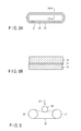
FIG. 1A is a front view of a conventional heat-resistant laminated conveyer belt; -
FIG. 1B is a cross-sectional view along with line IB-IB ofFIG. 1A ; -
FIG. 2 is an explanatory view of a corrugated paper production machine using a bonding method based on a pressurizing belt; -
FIG. 3A is an explanatory view showing a weave texture of a folded back portion of a seamless cloth; -
FIG. 3B is a pattern diagram showing one process of a weaving method using a plain-weave seamless loom; -
FIG. 3C is a pattern diagram showing one process of a weaving method using a plain-weave seamless loom; -
FIG. 3D is a pattern diagram showing one process of a weaving method using a plain-weave seamless loom; -
FIG. 3E is a perspective view showing a cylindrical woven fabric woven with the plain-weave seamless loom; -
FIG. 3F is an enlarged pattern diagram showing a part of the weave texture of the woven fabric shown inFIG. 3E ; -
FIG. 4A is an explanatory view showing a weave texture by a circular loom; -
FIG. 4B is a pattern diagram showing one process of a weaving method using the circular loom; -
FIG. 4C is an enlarged pattern diagram showing a part of the weave texture of the woven fabric woven with the circular loom; -
FIG. 5A is a plan view of the heat-resistant laminated conveyer belt according to Example 1; -
FIG. 5B is a cross-sectional view along with line VB-VB ofFIG. 5A ; and -
FIG. 6 is a pattern diagram showing a machine for testing the number of times of fracture bending fatigue. - Description of Embodiments Hereinafter, the heat-resistant laminated conveyer belt according to embodiments of the present invention will be described in more detail.
- As for the heat-resistant laminated conveyer belt according to the embodiments for example, the core and a material for a reinforcement layer are separately produced and they are laminated through a fluororesin film to be used as an adhesive layer.
- In this case, the fluororesin film to be used as an adhesive layer is not limited. Preferably usable examples thereof include a tetrafluoroethylene-perfluoroalkyl vinyl ether copolymer resin (PFA resin) film having the highest heat resistance in meltable fluororesin films, tetrafluoroethylene-hexafluoropropylene copolymer resin (FEP resin) film, and a modified polytetrafluoroethylene resin (modified PTFE resin) film.
- In order to avoid an uneven surface such as an overlap bonded area, a plain-weave seamless woven fabric is used for a core obtained by impregnating an aramid fiber woven fabric in a fluororesin dispersion and drying and sintering the fabric. In order to obtain high strength, the aramid fiber woven fabric is woven at the thread count near the limit. According to a first embodiment, dedicated research has been performed in order to achieve the thread count (amount of yarn per unit area) higher than that of a conventional product. As a result, the thread count as a whole has been increased by 1.1-fold by a method for increasing the diameter of yarn and reducing the yarn density (the number of yarn per constant interval). A 10% increase in hardness as the belt strength has been achieved by setting the thickness of the core to 1.0 mm or more and setting the mass to 1500 g/m2 or more. Further, in order to improve the traveling performance of the belt, S- and Z-twist weft yarns (yarns in the peripheral length direction of the belt) are alternatively arranged.
- The plain-weave seamless woven fabric has an advantage of having no uneven surface. However, a folded back portion is present as a defect of the weaving method. Thus, the strength of the folded back portion is lower than that of other portions and the working life of the belt may be determined by the strength of the folded back portion, which is a problem. That is, a so-called hollow-weaving method to obtain the plain-weave seamless woven fabric comprises arranging a warp (yarn in the width direction of the belt) with a
face warp yarn 41 and an under-warp yarn 42 as shown inFIG. 3A , allowing a weft yarn (yarn in the peripheral length direction of the belt) 43 to go back and forth twice to form a circular shape, and sequentially forming a tubular shape. In the hollow-weaving method, two folded back portions are formed between theface warp yarn 41 and the under-warp yarn 42. The arrangement of the weft yarn is shifted at one of the folded back portions during weaving because of the structure of the weave texture and the strength of the one folded back portion is lower than that of other portions. InFIG. 3A , a shaded area indicates theweft yarn 43 at the time of weaving (yarn in the peripheral length direction of the belt) and white areas indicatewarp yarns - An example of the hollow-weaving method will be described in detail with reference to
FIGS. 3B to 3F . As shown inFIG. 3B , theface warp yarn 41 and the under-warp yarn 42 are arranged one above the other. Then, aweft yarn 43 is woven into theface warp yarn 41, and theweft yarn 43 is folded back and woven into the under-warp yarn 42. The state so far is shown inFIG. 3C . As shown inFIG. 3D , theweft yarn 43 is folded back and woven into theface warp yarn 41. Thereafter, theweft yarn 43 is folded back and woven into the under-warp yarn 42. A cylindrical woven fabric shown inFIG. 3E is obtained by repeating a process of weaving theweft yarn 43 into theface warp yarn 41, folding back theweft yarn 43, weaving theweft yarn 43 into the under-warp yarn 42, and folding back theweft yarn 43. The peripheral length direction of the belt is indicated by L1 and the width direction of the belt is indicated by L2. Since the folding back of theweft yarn 43 is performed in two positions, two folded back portions X are present on the woven fabric. - An enlarged pattern diagram of the weave texture when a part of the obtained woven fabric is observed from the side of the
face warp yarn 41 is shown inFIG. 3F . Theweft yarn 43 and theface warp yarn 41 are arranged one above the other and then theface warp yarn 41 and theweft yarn 43 are arranged one above the other, resulting in formation of a plain-weave texture. Since a basket weaving method is employed, two of each of theface warp yarn 41, the under-warp yarn 42, and theweft yarn 43 are used.FIG. 3F shows a state that the number of each yarn is one and each yarn is woven back and forth once to describe the plain-weave texture as a matter of convenience. Actually, as exemplified inFIG. 3A , a process of weaving one weave pattern back and forth is repeated twice. - When the woven fabric woven by the method is used as a seamless material, the weft yarn during weaving becomes a yarn in the running direction when used as the belt. Thus, the strength of the folded back portion causes a problem. In a second embodiment, a seamless woven fabric obtained by using the circular loom which does not produce a folded back portion is employed as the core in place of the plain-weave seamless woven fabric. The method of weaving a fabric by the circular loom comprises arranging a warp (yarn in the width direction of the belt) 44 in a cylindrical shape as shown in
FIG. 4A , revolving a weft yarn (yarn in the peripheral length direction of the belt) 45 along thewarps 44 arranged in the cylindrical shape to form a circular shape, and sequentially forming a tubular shape. In the case of the hollow-weaving method, a folded portion is actually not present and no partial change in the weave texture is caused, resulting in achievement of 25% of increase in the belt strength. One process of a weaving method using the circular loom is shown inFIG. 4B . - A pattern diagram of a part of the weave texture of the obtained woven fabric is shown in
FIG. 4C . Thewarp yarn 44 and theweft yarn 45 are arranged one above the other and then theweft yarn 45 and thewarp yarn 44 are arranged one above the other, resulting in formation of a plain-weave texture. Since a basket weaving method is employed, two of each of thewarp yarn 44 and theweft yarn 45 are used.FIG. 4C shows a state that the number of each yarn is one and each yarn is woven back and forth once to describe the plain-weave texture as a matter of convenience. Actually, as exemplified inFIG. 4A , a process of weaving one weave pattern back and forth is repeated twice. - Subsequently, in the present invention, an improvement in the hardness, abrasion resistance, low abrasion properties of the reinforcement layer which have an effect on the working life of the conveyer belt has been examined in addition to the strength and it has been achieved. That is, the surface hardness of the reinforcement layer influences bonding properties of the liner and the core paper during corrugated board production. When the surface hardness is low, the belt contact pressure when pressurizing and adhering the liner and the core paper reduced and a failure of adhesion between the liner and the core paper may be caused. Then, as for the reinforcement layer obtained by impregnating an aramid fiber woven fabric to which stretch properties are applied in a fluororesin dispersion and drying and sintering the fabric, it is contemplated to increase the hardness by a method of increasing the mass per unit area of a knitted fabric which is employed to give stretch properties.
- However, there is a limit in the method. In the present invention, it is found that the hardness can be improved by thermal compression of a reinforcement layer material obtained by impregnating an aramid fiber woven fabric to which stretch properties are applied in a fluororesin dispersion and drying and sintering the fabric, followed by stacking the core and the reinforcement layer material as the laminated belt.
- Further, the abrasion resistance and friction characteristics of the reinforcement layer have a large effect on the working life of the laminated belt. That is, the working life of the laminated conveyer belt depends on a difference in coefficient of friction between an area with high depth of wear and an area with low depth of wear on the surface of the reinforcement layer (belt surface). A defect such that the liner peels off the core paper of the corrugated board occurs. The defect is judged as the lifetime of the belt and the belt is detached and exchanged.
- In the present invention, the abrasion resistance and the low-friction surface can be provided by stacking a PFA resin film on a reinforcement layer material which is thermally compressed and has a high hardness before the reinforcement layer material is incorporated into a belt. As a result, the lifetime of the belt can be significantly improved. Here, the thickness of the PFA resin film which can be suitably used is from about 50 to 1000 µm.
- Subsequently, specific examples of the present invention will be described with reference to the drawings. The embodiment is not limited to the description below.
-
FIGS. 5A and 5B should be referred to. Here,FIG. 5A is a plan view of the heat-resistant laminated conveyer belt andFIG. 5B shows a cross-sectional view along with line VB-VB ofFIG. 5A . Acore 21 has a thickness of 1.0 mm and a mass of 1500 g/m2 which is formed by impregnating an aramid fiber yarn hollow-woven (seamless) fabric described in Table 1 below in a PFA dispersion and drying and sintering the fabric. As for the weft yarn (yarn in the peripheral length direction of the belt) in Table 1, an S-twist weft yarn and a Z-twist weft yarn were alternately woven for each wood pipe. Areinforcement layer 23 having a thickness of 1.3 mm is formed on the core 21 (a so-called peripheral side) through a PFA film (adhesive layer) 22 having a thickness of 200 to 250 µm. Thereinforcement layer 23 was obtained by repeating several times a process of impregnating a knitted aramid fiber fabric in a PTFE dispersion, drying the resultant fabric, and sintering it by burning.
[Table 1]Table 1 Used yarn Density (yarn/25 mm) Weft yarn Trade name: Technora, manufactured by Teijin Limited 13 Warp yarn Trade name: Technora, manufactured by Teijin Limited 16 - The heat-resistant laminated conveyer belts of
FIGS. 5A and 5B are produced in the following manner. That is, thecore 21, theadhesive layer 22, and thereinforcement layer 23 are superimposed in this order. The resultant product is arranged between both sides of a heat press board and heat-sealed under conditions (press pressure: about 0.5 MPa, temperature: 350°C, retention time: 85 seconds). Subsequently, the operation was repeated while transferring the belt onto the heat press at a pitch of board side length until theadhesive layer 22 and thereinforcement layer 23 were heat-sealed on the whole of the seamless core. The heat-resistant laminated conveyer belt in an endless form was obtained by integrating theadhesive layer 22 and thereinforcement layer 23 by the process. - The heat-resistant laminated conveyer belt according to Example 1 has a configuration in which the
adhesive layer 22 and thereinforcement layer 23 are sequentially stacked on thecore 21. The aramid fiber woven fabric of thecore 21 is a woven fabric woven by the plain-weave seamless loom described in Table above and includes the S- and Z-weft yarns (yarns in the peripheral length direction of the belt) alternately arranged. The core is configured to have a thickness of 1.0 mm and a mass of 1500 g/m2. Therefore, according to Example 1, a heat-resistant laminated conveyer belt which is used as a pressurizing belt in a process of producing corrugated boards composed of various types of quality of paper can be obtained by increasing the overall hardness of a laminated conveyer belt, improving the surface hardness and abrasion resistance of the surface, and applying a low-friction surface. - Although it is not illustrated, a basic configuration of the heat-resistant laminated conveyer belt is similar to those of
FIGS. 5A and 5B . - The core is formed by impregnating a woven fabric woven by the circular loom for aramid fiber yarn described in Table 2 below in a PFA dispersion and drying and sintering the fabric and has a thickness of 1.3 mm and a mass of 1500 g/m2 or more. As for the weft yarn (yarn in the peripheral length direction of the belt) in Table 2, an S-twist weft yarn and a Z-twist weft yarn are alternately woven for each wood pipe. A reinforcement layer having a thickness of 1.3 mm is formed on the core through a PFA film (adhesive layer) having a thickness of 200 to 250 µm. The reinforcement layer was obtained by repeating several times a process of impregnating a knitted aramid fiber fabric in a PTFE dispersion, drying the resultant fabric, and sintering it by burning.
[Table 2]Table 2 Used yarn Density (yarn/25 mm) Weft yarn Trade name: Technora, Manufactured by Teijin Limited 12 Warp yarn Trade name: Technora, Manufactured by Teijin Limited 18 - The heat-resistant laminated conveyer belt of Example 2 is produced in the following manner. That is, the core, the adhesive layer, and the reinforcement layer are superimposed in this order. The resultant product is arranged between both sides of a heat press board and heat-sealed under conditions (press pressure: about 0.5 MPa, temperature: 350°C, retention time: 85 seconds). Subsequently, the operation was repeated while transferring the belt onto the heat press at a pitch of board side length until the adhesive layer and the reinforcement layer were heat-sealed on the whole of the seamless core. The heat-resistant laminated conveyer belt in an endless form was obtained by integrating the adhesive layer and the reinforcement layer by the process.
- The heat-resistant laminated conveyer belt according to Example 2 has a configuration in which the adhesive layer and the reinforcement layer are sequentially stacked on the core. The aramid fiber woven fabric of the core is a woven fabric woven by the circular loom for aramid fiber yarn described in Table 2 above and includes the S- and Z-weft yarns (yarns in the peripheral length direction of the belt) alternately arranged. The core is configured to have a thickness of 1.3 mm and a mass of 1500 g/m2. According to Example 2, when a seamless woven fabric obtained by using the circular loom which does not produce a folded back portion is employed as the core, the belt strength can be increased to about 25%.
- Although it is not illustrated, a basic configuration of the heat-resistant laminated conveyer belt is similar to those of
FIGS. 5A and 5B . - In Example 3, a reinforcement layer material having a thickness of 1.3 mm was obtained by repeating several times a process of impregnating a knitted aramid fiber fabric in a PTFE dispersion, drying the resultant fabric, and sintering it by burning. Then, the reinforcement layer material was arranged between both sides of a heat press board. The material was compression-molded under conditions (press pressure: about 0.7 MPa, temperature: 350°C, retention time: 85 seconds) to form a reinforcement layer having a thickness of 0.7 mm. Successively, the reinforcement layer was heat-sealed on the same core as Example 1 through a PFA film having a thickness of 250 µm as an adhesive layer. Heat-sealing conditions are similar to those of Example 1.
- According to Example 3, the hardness of the belt can be improved by using the material obtained by thermal compression molding the reinforcement layer in the thickness direction before the reinforcement layer is incorporated into the heat-resistant laminated conveyer belt.
- In Example 4 a PFA film having a thickness of 250 µm was superimposed on the heat-resistant laminated conveyer belt in an endless form obtained in Example 3. The resultant product was arranged between both sides of a heat press board and heat-sealed under conditions (press pressure: about 0.6 MPa, temperature: 340°C, retention time: 85 seconds). Subsequently, the operation was repeated while transferring the belt onto the heat press at a pitch of board side length until the PFA film was heat-sealed on the whole of the heat-resistant laminated conveyer belt. As a result, the heat-resistant laminated conveyer belt in an endless form was obtained by integrating the PFA film.
- The heat-resistant laminated conveyer belt according to Example 4 has a configuration in which the adhesive layer, I the reinforcement layer, and the PFA film are sequentially stacked on the core. The aramid fiber woven fabric of the core is a woven fabric woven by the plain-weave seamless loom described in Table 1 above and includes the S- and Z-weft yarns (yarns in the peripheral length direction of the belt) alternately arranged. The core is configured to be a woven fabric having a thickness of 1.0 mm and a mass of 1500 g/m2. In Example 4, a PFA resin film is stacked on a reinforcement layer material which is heat-compressed and has a high hardness before the reinforcement layer material is incorporated into a belt. Accordingly, abrasion resistance and a low-friction surface are provided, and thus the lifetime of the belt can be significantly improved.
- A core having a thickness of 0.8 mm which is formed by impregnating an aramid fiber yarn hollow-woven (seamless) fabric described in Table 3 below in a PFA dispersion and drying and sintering the fabric is formed. The mass of the core was 1420 g/m2. As for the weft yarn (yarn in the peripheral length direction of the belt) in Table 3, an S-twist weft yarn and a Z-twist weft yarn were alternately woven for each wood pipe. A
reinforcement layer 23 having a thickness of 1.3 mm is formed on the core through the PFA film (adhesive layer) 22 having a thickness of 200 to 250 µm. Thereinforcement layer 23 was obtained by repeating several times a process of impregnating a knitted aramid fiber fabric in a PTFE dispersion, drying the resultant fabric, and sintering it by burning. - Then, the core, the adhesive layer, and the reinforcement layer were superimposed in this order. The resultant product was arranged between both sides of a heat press board and heat-sealed under conditions (press pressure: about 0.5 MPa, temperature: 350°C, retention time: 85 seconds). Subsequently, the operation was repeated while transferring the belt onto the heat press at a pitch of board side length until the adhesive layer and the reinforcement layer were heat-sealed on the whole of the seamless core. The core, the adhesive layer and the reinforcement layer were integrated by the process and the heat-resistant laminated conveyer belt in an endless form was obtained.
- The heat-resistant laminated conveyer belts of Examples 1 to 5 were run in a temperature atmosphere of 180°C at a load 1.5 kN/cm width and a speed of 800 m/min with a testing device shown in
FIG. 6 , and then the fractural travel distance was examined. In this regard, inFIG. 6 , a drivingroll 31 drives a drivenroll 32 as well as aconveyer belt 33. A load in a direction of an arrow W is applied on aload roll 34. The results are shown in Table 4 below.
[Table 3]Table 3 Used yarn Density (yarn/25 mm) Weft yarn Trade name: Technora, manufactured by Teijin Limited 13 Warp yarn Trade name: Technora, manufactured by Teijin Limited 18 Table 4 Belt test sample Fractural travel distance (ten thousand/m) Example 1 2500 Example 2 3100 Example 3 2480 Example 4 2565 Example 5 1850 - When a Shore D hardness test of the belt surface was performed using the heat-resistant laminated conveyer belts of Example 3 and Example 5, the results shown in Table 5 below were obtained.
[Table 5]Table 5 Belt test sample Sore D hardness Example 3 65.5 Example 5 60.5
[Table 6]Table 6 Belt test sample Dynamic coefficient of friction of surface Initial state After polishing belt 50 timesExample 4 0.13 0.20 Example 5 0.12 0.29 - As is clear from Table 6, the dynamic coefficient of friction of the surface of the belt of Example 4 after polishing the
belt 50 times is lower than that of Example 5. Thus, when a core paper with rough texture is used, the core paper can be smoothly moved on the belt. The peripheral speeds of the belt at the center and the end in a belt width direction are different. According to Example 4, the core paper is smoothly moved on the belt, and thus peeling of the liner paper from the core paper due to a variation in the peripheral speed can be suppressed. - From the above results, it was demonstrated that the working life of the belts of Examples 1, 2, 3, and 4 as the heat-resistant laminated conveyer belt to be used for the corrugated board production machine could be significantly prolonged as compared with the belt shown in Example 5.
- The cores used in Examples had a thickness of 1.0 to 1.3 mm and a mass of 1500 g/m2, however they are not limited to these values if sufficient core strength is obtained. For example, even if the mass of the core to be used in Example 2 is changed to 1650 g/m2, the same effect can be obtained. The thickness of the core is preferably 1 mm or more and 3 mm or less. The mass of the core is preferably 1500 g/m2 or more and 3000 g/m2 or less.
- In Examples, as the aramid fiber woven fabric to which stretch properties were applied, the knitted aramid fiber fabric was used, however, it is not particularly limited thereto as long as it is an aramid fiber woven fabric with stretch properties. For example, an aramid fiber woven fabric produced by moss knitting, warp knitting (for example, Denbigh knitting, code knitting, and atlas knitting), weft knitting (for example, flat knitting, rib knitting, and pearl knitting) or the like has stretch properties, and thus they can be used.
- In Example 1, an S-twist weft yarn and a Z-twist weft yarn were alternatively arranged, and the interval of the S-twist weft yarn and the interval of the Z-twist weft yarn were respectively set to about 25 mm. However, the present invention is not limited to the arrangement. The S-twist weft yarn and the Z-twist weft yarn may be arranged across the warp in the width direction of the belt. For example, two of the S-twist weft yarns and two of the Z-twist weft yarns can be alternatively arranged (S, S, Z, Z). In this case, the changing of the S-twist weft yarn to the Z-twist weft yarn is performed at intervals of about 50 mm.
- In Example 2, an S-twist weft yarn and an Z-twist weft yarn were alternatively arranged, however the present invention is not limited to the arrangement. In the case of the circular loom used in Example 2, a yarn can be woven in a spiral form, for example, by a simultaneous rotation of three to four shuttles. Thus, a certain number of the weft yarns can be alternatively woven by changing a direction of twisting yarns which are set to the shuttles to the S-twist or the Z-twist. Accordingly, the yarn arrangement is easily changed as compared with the case of the shuttle loom used in Example 1. Thus, for example, in addition to the alternative arrangement of two of the S-twist weft yarns and two of the Z-twist weft yarns (S, S, Z, Z), three of the S-twist weft yarns and three of the Z-twist weft yarns can be alternatively arranged (S, S, S, Z, Z, Z).
- When one or more of the S-twist weft yarns and one or more of the Z-twist weft yarns are alternatively arranged, the stress to be applied to the belt can be relaxed. This enables the traveling performance of the belt to be improved. In order to arrange the S-twist weft yarn and the Z-twist weft yarn with respect to the warp, the number of the S-twist weft yarn and the number of the Z-twist weft yarn are desirably equal so as to perform the changing of the S-twist weft yarn to the Z-twist weft yarn at equal intervals.
- It is to be noted that the present invention is not limited to the above embodiments as they are, and in an implementing stage, constituent elements can be modified and embodied without departing from the scope of the present invention. Moreover, an appropriate combination of a plurality of constituent elements disclosed in the above embodiments can form various inventions. For example, several constituent elements may be deleted from all the constituent elements described in the embodiments. Furthermore, the constituent elements of the different embodiments may appropriately be combined.
- 11...Upper roll; 12...Lower roll; 13a, 13b...Pressure roll; 14...Pressurizing roll; 15...Core paper; 16...Corrugated board liner; 17...Single-faced corrugated board sheet; 21...Core; 22...Adhesive layer; 23...Reinforcement layer; 41...face warp yarn; 42...Under-warp yarn; 43, 44...Weft yarn; 45 ... Warp yarn
Claims (10)
- A heat-resistant laminated conveyer belt comprising:a fluororesin-coated core obtained by impregnating an aramid fiber woven fabric in a fluororesin dispersion and drying and sintering the fabric; and a reinforcement layer which is formed on the core through an adhesive layer and obtained by impregnating an aramid fiber woven fabric to which stretch properties are applied in a fluororesin dispersion and drying and sintering the fabric;wherein the aramid fiber woven fabric of the core is a woven fabric by a plain-weave seamless loom and the woven fabric includes an S-twist weft yarn and a Z-twist weft yarn which are alternatively arranged.
- The heat-resistant laminated conveyer belt according to claim 1,
wherein the core has a thickness of 1.0 mm or more and a mass of 1500 g/m2 or more. - The heat-resistant laminated conveyer belt according to claim 1,
wherein the reinforcement layer is thermal compression-molded in the thickness direction before the reinforcement layer is incorporated into the heat-resistant laminated conveyer belt. - The heat-resistant laminated conveyer belt according to claim 1, further comprising:a tetrafluoroethylene-perfluoroalkyl vinyl ether copolymer resin layer formed on the reinforcement layer.
- The heat-resistant laminated conveyer belt according to claim 1,
wherein the number of the S-twist weft yarn and the number of the Z-twist weft yarn are plural. - A heat-resistant laminated conveyer belt comprising:a fluororesin-coated core obtained by impregnating an aramid fiber woven fabric in a fluororesin dispersion and drying and sintering the fabric; anda reinforcement layer which is formed on the core through an adhesive layer and obtained by impregnating an aramid fiber woven fabric to which stretch properties are applied in a fluororesin dispersion and drying and sintering the fabric;wherein the aramid fiber woven fabric of the core is a woven fabric by a circular loom and the woven fabric includes an S-twist weft yarn and a Z-twist weft yarn which are alternatively arranged.
- The heat-resistant laminated conveyer belt according to claim 6,
wherein the core has a thickness of 1.0 mm or more and a mass of 1500 g/m2 or more. - The heat-resistant laminated conveyer belt according to claim 6,
wherein the reinforcement layer which is thermal compression-molded in the thickness direction before the reinforcement layer is incorporated into the heat-resistant laminated conveyer belt. - The heat-resistant laminated conveyer belt according to claim 6, further comprising:a tetrafluoroethylene-perfluoroalkyl vinyl ether copolymer resin layer formed on the reinforcement layer.
- The heat-resistant laminated conveyer belt according to claim 6,
wherein the number of the S-twist weft yarn and the number of the Z-twist weft yarn are plural.
Applications Claiming Priority (2)
| Application Number | Priority Date | Filing Date | Title |
|---|---|---|---|
| JP2009160995 | 2009-07-07 | ||
| PCT/JP2010/061554 WO2011004848A1 (en) | 2009-07-07 | 2010-07-07 | Heat-resistant laminated conveyor belt |
Publications (3)
| Publication Number | Publication Date |
|---|---|
| EP2452901A1 true EP2452901A1 (en) | 2012-05-16 |
| EP2452901A4 EP2452901A4 (en) | 2016-12-21 |
| EP2452901B1 EP2452901B1 (en) | 2019-03-27 |
Family
ID=43429272
Family Applications (1)
| Application Number | Title | Priority Date | Filing Date |
|---|---|---|---|
| EP10797159.0A Active EP2452901B1 (en) | 2009-07-07 | 2010-07-07 | Heat-resistant laminated conveyor belt |
Country Status (6)
| Country | Link |
|---|---|
| US (2) | US20120108133A1 (en) |
| EP (1) | EP2452901B1 (en) |
| JP (2) | JP5420664B2 (en) |
| KR (3) | KR101621357B1 (en) |
| CN (3) | CN106429185B (en) |
| WO (1) | WO2011004848A1 (en) |
Cited By (1)
| Publication number | Priority date | Publication date | Assignee | Title |
|---|---|---|---|---|
| EP3666691A4 (en) * | 2017-08-10 | 2021-04-28 | Honda Sangyo Co., Ltd. | Multilayered seamless belt and production method therefor |
Families Citing this family (10)
| Publication number | Priority date | Publication date | Assignee | Title |
|---|---|---|---|---|
| CN102275378A (en) * | 2011-04-02 | 2011-12-14 | 上海永利带业股份有限公司 | TPU (thermoplastic polyurethane) light conveyer belt in printing and dyeing industry and manufacturing method thereof |
| ITVE20130038A1 (en) * | 2013-07-22 | 2015-01-23 | Giorgio Trani | MACHINE AND METHOD TO REALIZE A FIBER MATERIAL TAPE WITH HIGH LONGITUDINAL AND TRANSVERSAL EXTENSIBILITY. |
| CN103770392B (en) * | 2014-01-02 | 2015-12-30 | 芜湖华烨工业用布有限公司 | A kind of composite industrial cloth for industrial transport tape |
| FR3019609B1 (en) * | 2014-04-03 | 2016-05-13 | Hutchinson | POWER TRANSMISSION BELT. |
| CN108602623B (en) * | 2015-12-10 | 2020-06-26 | 康蒂泰克传送带系统有限公司 | Heat-resistant conveyor belt |
| TWI611069B (en) * | 2016-02-16 | 2018-01-11 | 聖高拜塑膠製品公司 | Composite and method for making |
| JP7059523B2 (en) * | 2017-06-12 | 2022-04-26 | 横浜ゴム株式会社 | Conveyor belt joining method |
| CN110963237A (en) * | 2019-12-20 | 2020-04-07 | 上海永利带业股份有限公司 | A small size flame retardant conveyor belt |
| CN115091822B (en) * | 2022-07-20 | 2024-01-23 | 浙江凯耀新材料科技有限公司 | Belt with flat joint for producing same-penetration plastic floor and production method thereof |
| CN115107333B (en) * | 2022-07-20 | 2024-01-23 | 浙江凯耀新材料科技有限公司 | Belt for producing same-penetration plastic floor, production method and application thereof |
Family Cites Families (28)
| Publication number | Priority date | Publication date | Assignee | Title |
|---|---|---|---|---|
| US3924482A (en) | 1974-01-10 | 1975-12-09 | Dayco Corp | Endless power transmission belt and method of making same |
| US4052243A (en) | 1975-01-28 | 1977-10-04 | Polymer Processing Research Institute Ltd. | Method for producing a cross-laminated cloth-like product from wide warp and weft webs |
| JP2584218B2 (en) | 1986-11-25 | 1997-02-26 | 株式会社 ヌ−ベル絵具研究所 | How to make cracks on the surface of paper, pottery, etc. |
| JPS63246532A (en) | 1987-03-31 | 1988-10-13 | Bando Chem Ind Ltd | power transmission belt |
| JP2840143B2 (en) * | 1991-09-04 | 1998-12-24 | 篤識 北村 | Manufacturing method for seamless tube products |
| JP3173884B2 (en) * | 1992-09-24 | 2001-06-04 | バンドー化学株式会社 | belt |
| JP2510458B2 (en) * | 1992-09-28 | 1996-06-26 | 三ツ星ベルト株式会社 | Wide belt canvas core |
| JP2584218Y2 (en) * | 1993-02-12 | 1998-10-30 | 中興化成工業株式会社 | Heat resistant laminated conveyor belt |
| DE69404571T2 (en) * | 1993-02-23 | 1998-02-26 | Ashimori Ind Co Ltd | TIMING BELT |
| US5421450A (en) * | 1994-05-31 | 1995-06-06 | Chukoh Chemical Industries, Ltd. | Heat-resistant, laminated conveyer belt |
| JP2972978B2 (en) * | 1994-08-29 | 1999-11-08 | 三ツ星ベルト株式会社 | Canvas core for wide belt and method of manufacturing same |
| CN1139901A (en) * | 1994-10-28 | 1997-01-08 | 陶氏化学公司 | Improved process for resin transfer molding |
| JPH10119152A (en) | 1996-10-16 | 1998-05-12 | Atsusato Kitamura | Pressure contact belt for corrugation processing and production of corrugated article |
| JPH11105171A (en) * | 1997-10-01 | 1999-04-20 | Atsusato Kitamura | Pressure contact belt for corrugation processing and production of corrugated processed article |
| DE19751162A1 (en) | 1997-11-19 | 1999-05-20 | Bhs Corr Masch & Anlagenbau | Machine for producing a web of corrugated cardboard laminated at least on one side |
| JPH11301825A (en) * | 1998-04-20 | 1999-11-02 | Ichikawa Woolen Textile Co Ltd | Pressurized belt for bonding paper |
| JPH11322036A (en) * | 1998-05-15 | 1999-11-24 | Yoshiharu Murayama | Conveyor belt |
| JP2000103511A (en) * | 1998-09-29 | 2000-04-11 | Atsusato Kitamura | Looplike belt |
| JP2000168930A (en) | 1998-12-04 | 2000-06-20 | Gunze Ltd | Bending resistant carrying belt |
| IT1312002B1 (en) * | 1999-03-31 | 2002-03-22 | Gividi Italia Spa | REINFORCEMENT FABRIC TO OPTIMIZE DIMENSIONAL STABILITY LAMINATED COMPOSITE STRUCTURES, INCLUDING PRODUCTS FOR APPLICATIONS |
| JP2001134107A (en) * | 1999-11-01 | 2001-05-18 | Bando Chem Ind Ltd | Belt for electrophotographic equipment |
| CN2542618Y (en) * | 2002-05-14 | 2003-04-02 | 沈阳兴中制带有限公司 | Strong heat-resisting conveyer belt |
| US7049365B2 (en) * | 2003-01-06 | 2006-05-23 | E. I. Du Pont De Nemours And Company | Fluoropolymer sealant |
| JP4459586B2 (en) | 2003-10-01 | 2010-04-28 | 中興化成工業株式会社 | Heat-resistant laminated conveyor belt for corrugated paper manufacture |
| US8056707B2 (en) | 2004-05-19 | 2011-11-15 | Mitsubishi Heavy Industries Printing & Packaging Machinery, Ltd. | Heat resistant laminated conveyor belt and manufacturing method thereof |
| KR101348269B1 (en) * | 2005-04-05 | 2014-01-08 | 쿼드란트 플라스틱 컴포지츠 아게 | Method for producing a thermoplastically deformable fiber-reinforced semifinished product |
| US8192317B2 (en) * | 2006-11-22 | 2012-06-05 | Veyance Technologies, Inc. | Reinforced belt for powerturn applications |
| CN101428705B (en) * | 2008-12-15 | 2011-09-28 | 浙江东南橡胶机带有限公司 | Phase-change fire resistant conveyer belt |
-
2010
- 2010-07-07 CN CN201610819799.6A patent/CN106429185B/en active Active
- 2010-07-07 WO PCT/JP2010/061554 patent/WO2011004848A1/en not_active Ceased
- 2010-07-07 KR KR1020147021363A patent/KR101621357B1/en active Active
- 2010-07-07 CN CN201610820884.4A patent/CN106395242B/en active Active
- 2010-07-07 EP EP10797159.0A patent/EP2452901B1/en active Active
- 2010-07-07 CN CN201080030205.4A patent/CN102470987B/en active Active
- 2010-07-07 KR KR1020127000135A patent/KR101666560B1/en active Active
- 2010-07-07 JP JP2011521947A patent/JP5420664B2/en active Active
- 2010-07-07 KR KR1020167028004A patent/KR101791068B1/en active Active
-
2012
- 2012-01-05 US US13/344,467 patent/US20120108133A1/en not_active Abandoned
-
2013
- 2013-11-18 JP JP2013238239A patent/JP5887325B2/en active Active
-
2015
- 2015-04-03 US US14/678,721 patent/US9643347B2/en active Active
Non-Patent Citations (1)
| Title |
|---|
| See references of WO2011004848A1 * |
Cited By (1)
| Publication number | Priority date | Publication date | Assignee | Title |
|---|---|---|---|---|
| EP3666691A4 (en) * | 2017-08-10 | 2021-04-28 | Honda Sangyo Co., Ltd. | Multilayered seamless belt and production method therefor |
Also Published As
| Publication number | Publication date |
|---|---|
| CN106395242B (en) | 2019-01-22 |
| CN102470987B (en) | 2016-10-19 |
| CN102470987A (en) | 2012-05-23 |
| JP5420664B2 (en) | 2014-02-19 |
| US20150217490A1 (en) | 2015-08-06 |
| CN106429185B (en) | 2019-05-14 |
| JPWO2011004848A1 (en) | 2012-12-20 |
| US20120108133A1 (en) | 2012-05-03 |
| EP2452901B1 (en) | 2019-03-27 |
| CN106429185A (en) | 2017-02-22 |
| KR20140104050A (en) | 2014-08-27 |
| CN106395242A (en) | 2017-02-15 |
| KR20120024933A (en) | 2012-03-14 |
| KR20160120808A (en) | 2016-10-18 |
| KR101791068B1 (en) | 2017-10-27 |
| KR101621357B1 (en) | 2016-05-16 |
| JP2014094836A (en) | 2014-05-22 |
| JP5887325B2 (en) | 2016-03-16 |
| WO2011004848A1 (en) | 2011-01-13 |
| KR101666560B1 (en) | 2016-10-14 |
| US9643347B2 (en) | 2017-05-09 |
| EP2452901A4 (en) | 2016-12-21 |
Similar Documents
| Publication | Publication Date | Title |
|---|---|---|
| US9643347B2 (en) | Heat-resistant laminated conveyer belt | |
| EP3342906B1 (en) | Textile machine belt | |
| CA2557618C (en) | Heat resistant laminated conveyor belt and manufacturing method thereof | |
| FI85889B (en) | AENDLOEST BAELTE FOER ANVAENDNING I PAPPERSTILLVERKNINGSPROCESSENS PRESSDEL FOER AVLAEGSNANDE AV VATTEN. | |
| EP2028317B1 (en) | Belt for shoe press | |
| CA2349553C (en) | Interwoven belt fabric | |
| JP4593326B2 (en) | Shoe press belt | |
| JP6770901B2 (en) | Conveying belt and manufacturing method of conveying belt | |
| KR20120006442A (en) | Chip split stepless belt | |
| JPH11322036A (en) | Conveyor belt | |
| JPH11105171A (en) | Pressure contact belt for corrugation processing and production of corrugated processed article | |
| JP5559923B1 (en) | Split belt and split device | |
| JP2004182407A (en) | Corrugator belt | |
| JP2002211727A (en) | Conveyor belt | |
| JP2015227522A (en) | Felt for papermaking | |
| JP2000249194A (en) | Tape cylindrical structure |
Legal Events
| Date | Code | Title | Description |
|---|---|---|---|
| PUAI | Public reference made under article 153(3) epc to a published international application that has entered the european phase |
Free format text: ORIGINAL CODE: 0009012 |
|
| 17P | Request for examination filed |
Effective date: 20120106 |
|
| AK | Designated contracting states |
Kind code of ref document: A1 Designated state(s): AL AT BE BG CH CY CZ DE DK EE ES FI FR GB GR HR HU IE IS IT LI LT LU LV MC MK MT NL NO PL PT RO SE SI SK SM TR |
|
| RIN1 | Information on inventor provided before grant (corrected) |
Inventor name: NITTA, TAKASHI Inventor name: YAMAKAWA, KIMIHIRO Inventor name: FUTATSUKI, KEIGO Inventor name: HARAGUCHI, TOMOMI Inventor name: MIZUSHIMA, KAZUKI Inventor name: IMAZATO, HIDEO |
|
| DAX | Request for extension of the european patent (deleted) | ||
| RA4 | Supplementary search report drawn up and despatched (corrected) |
Effective date: 20161118 |
|
| RIC1 | Information provided on ipc code assigned before grant |
Ipc: B65G 15/38 20060101ALI20161114BHEP Ipc: B65G 15/34 20060101ALI20161114BHEP Ipc: B65G 15/30 20060101AFI20161114BHEP |
|
| STAA | Information on the status of an ep patent application or granted ep patent |
Free format text: STATUS: EXAMINATION IS IN PROGRESS |
|
| 17Q | First examination report despatched |
Effective date: 20180328 |
|
| RAP1 | Party data changed (applicant data changed or rights of an application transferred) |
Owner name: MITSUBISHI HEAVY INDUSTRIES MACHINERY SYSTEMS, LTD Owner name: CHUKOH CHEMICAL INDUSTRIES, LTD. |
|
| GRAP | Despatch of communication of intention to grant a patent |
Free format text: ORIGINAL CODE: EPIDOSNIGR1 |
|
| STAA | Information on the status of an ep patent application or granted ep patent |
Free format text: STATUS: GRANT OF PATENT IS INTENDED |
|
| INTG | Intention to grant announced |
Effective date: 20181019 |
|
| GRAS | Grant fee paid |
Free format text: ORIGINAL CODE: EPIDOSNIGR3 |
|
| GRAA | (expected) grant |
Free format text: ORIGINAL CODE: 0009210 |
|
| STAA | Information on the status of an ep patent application or granted ep patent |
Free format text: STATUS: THE PATENT HAS BEEN GRANTED |
|
| AK | Designated contracting states |
Kind code of ref document: B1 Designated state(s): AL AT BE BG CH CY CZ DE DK EE ES FI FR GB GR HR HU IE IS IT LI LT LU LV MC MK MT NL NO PL PT RO SE SI SK SM TR |
|
| REG | Reference to a national code |
Ref country code: GB Ref legal event code: FG4D |
|
| REG | Reference to a national code |
Ref country code: CH Ref legal event code: EP |
|
| REG | Reference to a national code |
Ref country code: AT Ref legal event code: REF Ref document number: 1112782 Country of ref document: AT Kind code of ref document: T Effective date: 20190415 |
|
| REG | Reference to a national code |
Ref country code: IE Ref legal event code: FG4D |
|
| REG | Reference to a national code |
Ref country code: DE Ref legal event code: R096 Ref document number: 602010057870 Country of ref document: DE |
|
| PG25 | Lapsed in a contracting state [announced via postgrant information from national office to epo] |
Ref country code: FI Free format text: LAPSE BECAUSE OF FAILURE TO SUBMIT A TRANSLATION OF THE DESCRIPTION OR TO PAY THE FEE WITHIN THE PRESCRIBED TIME-LIMIT Effective date: 20190327 Ref country code: NO Free format text: LAPSE BECAUSE OF FAILURE TO SUBMIT A TRANSLATION OF THE DESCRIPTION OR TO PAY THE FEE WITHIN THE PRESCRIBED TIME-LIMIT Effective date: 20190627 Ref country code: SE Free format text: LAPSE BECAUSE OF FAILURE TO SUBMIT A TRANSLATION OF THE DESCRIPTION OR TO PAY THE FEE WITHIN THE PRESCRIBED TIME-LIMIT Effective date: 20190327 Ref country code: LT Free format text: LAPSE BECAUSE OF FAILURE TO SUBMIT A TRANSLATION OF THE DESCRIPTION OR TO PAY THE FEE WITHIN THE PRESCRIBED TIME-LIMIT Effective date: 20190327 |
|
| REG | Reference to a national code |
Ref country code: NL Ref legal event code: MP Effective date: 20190327 |
|
| PG25 | Lapsed in a contracting state [announced via postgrant information from national office to epo] |
Ref country code: HR Free format text: LAPSE BECAUSE OF FAILURE TO SUBMIT A TRANSLATION OF THE DESCRIPTION OR TO PAY THE FEE WITHIN THE PRESCRIBED TIME-LIMIT Effective date: 20190327 Ref country code: BG Free format text: LAPSE BECAUSE OF FAILURE TO SUBMIT A TRANSLATION OF THE DESCRIPTION OR TO PAY THE FEE WITHIN THE PRESCRIBED TIME-LIMIT Effective date: 20190627 Ref country code: NL Free format text: LAPSE BECAUSE OF FAILURE TO SUBMIT A TRANSLATION OF THE DESCRIPTION OR TO PAY THE FEE WITHIN THE PRESCRIBED TIME-LIMIT Effective date: 20190327 Ref country code: LV Free format text: LAPSE BECAUSE OF FAILURE TO SUBMIT A TRANSLATION OF THE DESCRIPTION OR TO PAY THE FEE WITHIN THE PRESCRIBED TIME-LIMIT Effective date: 20190327 Ref country code: GR Free format text: LAPSE BECAUSE OF FAILURE TO SUBMIT A TRANSLATION OF THE DESCRIPTION OR TO PAY THE FEE WITHIN THE PRESCRIBED TIME-LIMIT Effective date: 20190628 |
|
| REG | Reference to a national code |
Ref country code: AT Ref legal event code: MK05 Ref document number: 1112782 Country of ref document: AT Kind code of ref document: T Effective date: 20190327 |
|
| PG25 | Lapsed in a contracting state [announced via postgrant information from national office to epo] |
Ref country code: SK Free format text: LAPSE BECAUSE OF FAILURE TO SUBMIT A TRANSLATION OF THE DESCRIPTION OR TO PAY THE FEE WITHIN THE PRESCRIBED TIME-LIMIT Effective date: 20190327 Ref country code: EE Free format text: LAPSE BECAUSE OF FAILURE TO SUBMIT A TRANSLATION OF THE DESCRIPTION OR TO PAY THE FEE WITHIN THE PRESCRIBED TIME-LIMIT Effective date: 20190327 Ref country code: PT Free format text: LAPSE BECAUSE OF FAILURE TO SUBMIT A TRANSLATION OF THE DESCRIPTION OR TO PAY THE FEE WITHIN THE PRESCRIBED TIME-LIMIT Effective date: 20190727 Ref country code: AL Free format text: LAPSE BECAUSE OF FAILURE TO SUBMIT A TRANSLATION OF THE DESCRIPTION OR TO PAY THE FEE WITHIN THE PRESCRIBED TIME-LIMIT Effective date: 20190327 Ref country code: CZ Free format text: LAPSE BECAUSE OF FAILURE TO SUBMIT A TRANSLATION OF THE DESCRIPTION OR TO PAY THE FEE WITHIN THE PRESCRIBED TIME-LIMIT Effective date: 20190327 Ref country code: RO Free format text: LAPSE BECAUSE OF FAILURE TO SUBMIT A TRANSLATION OF THE DESCRIPTION OR TO PAY THE FEE WITHIN THE PRESCRIBED TIME-LIMIT Effective date: 20190327 Ref country code: ES Free format text: LAPSE BECAUSE OF FAILURE TO SUBMIT A TRANSLATION OF THE DESCRIPTION OR TO PAY THE FEE WITHIN THE PRESCRIBED TIME-LIMIT Effective date: 20190327 |
|
| PG25 | Lapsed in a contracting state [announced via postgrant information from national office to epo] |
Ref country code: SM Free format text: LAPSE BECAUSE OF FAILURE TO SUBMIT A TRANSLATION OF THE DESCRIPTION OR TO PAY THE FEE WITHIN THE PRESCRIBED TIME-LIMIT Effective date: 20190327 Ref country code: PL Free format text: LAPSE BECAUSE OF FAILURE TO SUBMIT A TRANSLATION OF THE DESCRIPTION OR TO PAY THE FEE WITHIN THE PRESCRIBED TIME-LIMIT Effective date: 20190327 |
|
| PG25 | Lapsed in a contracting state [announced via postgrant information from national office to epo] |
Ref country code: AT Free format text: LAPSE BECAUSE OF FAILURE TO SUBMIT A TRANSLATION OF THE DESCRIPTION OR TO PAY THE FEE WITHIN THE PRESCRIBED TIME-LIMIT Effective date: 20190327 Ref country code: IS Free format text: LAPSE BECAUSE OF FAILURE TO SUBMIT A TRANSLATION OF THE DESCRIPTION OR TO PAY THE FEE WITHIN THE PRESCRIBED TIME-LIMIT Effective date: 20190727 |
|
| REG | Reference to a national code |
Ref country code: DE Ref legal event code: R097 Ref document number: 602010057870 Country of ref document: DE |
|
| PG25 | Lapsed in a contracting state [announced via postgrant information from national office to epo] |
Ref country code: DK Free format text: LAPSE BECAUSE OF FAILURE TO SUBMIT A TRANSLATION OF THE DESCRIPTION OR TO PAY THE FEE WITHIN THE PRESCRIBED TIME-LIMIT Effective date: 20190327 |
|
| PLBE | No opposition filed within time limit |
Free format text: ORIGINAL CODE: 0009261 |
|
| STAA | Information on the status of an ep patent application or granted ep patent |
Free format text: STATUS: NO OPPOSITION FILED WITHIN TIME LIMIT |
|
| PG25 | Lapsed in a contracting state [announced via postgrant information from national office to epo] |
Ref country code: MC Free format text: LAPSE BECAUSE OF FAILURE TO SUBMIT A TRANSLATION OF THE DESCRIPTION OR TO PAY THE FEE WITHIN THE PRESCRIBED TIME-LIMIT Effective date: 20190327 Ref country code: SI Free format text: LAPSE BECAUSE OF FAILURE TO SUBMIT A TRANSLATION OF THE DESCRIPTION OR TO PAY THE FEE WITHIN THE PRESCRIBED TIME-LIMIT Effective date: 20190327 |
|
| REG | Reference to a national code |
Ref country code: CH Ref legal event code: PL |
|
| 26N | No opposition filed |
Effective date: 20200103 |
|
| GBPC | Gb: european patent ceased through non-payment of renewal fee |
Effective date: 20190707 |
|
| PG25 | Lapsed in a contracting state [announced via postgrant information from national office to epo] |
Ref country code: TR Free format text: LAPSE BECAUSE OF FAILURE TO SUBMIT A TRANSLATION OF THE DESCRIPTION OR TO PAY THE FEE WITHIN THE PRESCRIBED TIME-LIMIT Effective date: 20190327 |
|
| REG | Reference to a national code |
Ref country code: BE Ref legal event code: MM Effective date: 20190731 |
|
| PG25 | Lapsed in a contracting state [announced via postgrant information from national office to epo] |
Ref country code: GB Free format text: LAPSE BECAUSE OF NON-PAYMENT OF DUE FEES Effective date: 20190707 |
|
| PG25 | Lapsed in a contracting state [announced via postgrant information from national office to epo] |
Ref country code: LU Free format text: LAPSE BECAUSE OF NON-PAYMENT OF DUE FEES Effective date: 20190707 Ref country code: CH Free format text: LAPSE BECAUSE OF NON-PAYMENT OF DUE FEES Effective date: 20190731 Ref country code: BE Free format text: LAPSE BECAUSE OF NON-PAYMENT OF DUE FEES Effective date: 20190731 Ref country code: LI Free format text: LAPSE BECAUSE OF NON-PAYMENT OF DUE FEES Effective date: 20190731 |
|
| PG25 | Lapsed in a contracting state [announced via postgrant information from national office to epo] |
Ref country code: FR Free format text: LAPSE BECAUSE OF NON-PAYMENT OF DUE FEES Effective date: 20190731 |
|
| PG25 | Lapsed in a contracting state [announced via postgrant information from national office to epo] |
Ref country code: IE Free format text: LAPSE BECAUSE OF NON-PAYMENT OF DUE FEES Effective date: 20190707 |
|
| PG25 | Lapsed in a contracting state [announced via postgrant information from national office to epo] |
Ref country code: CY Free format text: LAPSE BECAUSE OF FAILURE TO SUBMIT A TRANSLATION OF THE DESCRIPTION OR TO PAY THE FEE WITHIN THE PRESCRIBED TIME-LIMIT Effective date: 20190327 |
|
| PG25 | Lapsed in a contracting state [announced via postgrant information from national office to epo] |
Ref country code: MT Free format text: LAPSE BECAUSE OF FAILURE TO SUBMIT A TRANSLATION OF THE DESCRIPTION OR TO PAY THE FEE WITHIN THE PRESCRIBED TIME-LIMIT Effective date: 20190327 Ref country code: HU Free format text: LAPSE BECAUSE OF FAILURE TO SUBMIT A TRANSLATION OF THE DESCRIPTION OR TO PAY THE FEE WITHIN THE PRESCRIBED TIME-LIMIT; INVALID AB INITIO Effective date: 20100707 |
|
| PG25 | Lapsed in a contracting state [announced via postgrant information from national office to epo] |
Ref country code: MK Free format text: LAPSE BECAUSE OF FAILURE TO SUBMIT A TRANSLATION OF THE DESCRIPTION OR TO PAY THE FEE WITHIN THE PRESCRIBED TIME-LIMIT Effective date: 20190327 |
|
| PGFP | Annual fee paid to national office [announced via postgrant information from national office to epo] |
Ref country code: DE Payment date: 20250722 Year of fee payment: 16 |
|
| PGFP | Annual fee paid to national office [announced via postgrant information from national office to epo] |
Ref country code: IT Payment date: 20250617 Year of fee payment: 16 |