JP4593326B2 - Shoe press belt - Google Patents
Shoe press belt Download PDFInfo
- Publication number
- JP4593326B2 JP4593326B2 JP2005076216A JP2005076216A JP4593326B2 JP 4593326 B2 JP4593326 B2 JP 4593326B2 JP 2005076216 A JP2005076216 A JP 2005076216A JP 2005076216 A JP2005076216 A JP 2005076216A JP 4593326 B2 JP4593326 B2 JP 4593326B2
- Authority
- JP
- Japan
- Prior art keywords
- layer
- shoe
- lattice
- mandrel
- shoe press
- Prior art date
- Legal status (The legal status is an assumption and is not a legal conclusion. Google has not performed a legal analysis and makes no representation as to the accuracy of the status listed.)
- Active
Links
- 239000000463 material Substances 0.000 claims description 74
- 229920005989 resin Polymers 0.000 claims description 26
- 239000011347 resin Substances 0.000 claims description 26
- 238000002844 melting Methods 0.000 claims description 2
- 230000008018 melting Effects 0.000 claims description 2
- 239000010410 layer Substances 0.000 description 126
- 241000226585 Antennaria plantaginifolia Species 0.000 description 18
- 238000004519 manufacturing process Methods 0.000 description 17
- 239000000758 substrate Substances 0.000 description 16
- 238000000034 method Methods 0.000 description 12
- 239000002759 woven fabric Substances 0.000 description 10
- 239000004744 fabric Substances 0.000 description 7
- 230000000052 comparative effect Effects 0.000 description 6
- 238000004804 winding Methods 0.000 description 6
- 229920002803 thermoplastic polyurethane Polymers 0.000 description 5
- 229920001187 thermosetting polymer Polymers 0.000 description 5
- 230000015572 biosynthetic process Effects 0.000 description 4
- 238000012360 testing method Methods 0.000 description 4
- 239000004677 Nylon Substances 0.000 description 3
- 239000004760 aramid Substances 0.000 description 3
- 229920003235 aromatic polyamide Polymers 0.000 description 3
- 239000000835 fiber Substances 0.000 description 3
- 238000010438 heat treatment Methods 0.000 description 3
- 229920001778 nylon Polymers 0.000 description 3
- 230000000704 physical effect Effects 0.000 description 3
- 238000000926 separation method Methods 0.000 description 3
- 239000004698 Polyethylene Substances 0.000 description 2
- 239000004642 Polyimide Substances 0.000 description 2
- 125000003118 aryl group Chemical group 0.000 description 2
- 239000003795 chemical substances by application Substances 0.000 description 2
- 238000007796 conventional method Methods 0.000 description 2
- 239000011162 core material Substances 0.000 description 2
- 238000005520 cutting process Methods 0.000 description 2
- 229920001971 elastomer Polymers 0.000 description 2
- -1 polyethylene Polymers 0.000 description 2
- 229920000573 polyethylene Polymers 0.000 description 2
- 229920000139 polyethylene terephthalate Polymers 0.000 description 2
- 239000005020 polyethylene terephthalate Substances 0.000 description 2
- 229920001721 polyimide Polymers 0.000 description 2
- 229920005749 polyurethane resin Polymers 0.000 description 2
- 239000002994 raw material Substances 0.000 description 2
- 229920002994 synthetic fiber Polymers 0.000 description 2
- 239000012209 synthetic fiber Substances 0.000 description 2
- RTTZISZSHSCFRH-UHFFFAOYSA-N 1,3-bis(isocyanatomethyl)benzene Chemical compound O=C=NCC1=CC=CC(CN=C=O)=C1 RTTZISZSHSCFRH-UHFFFAOYSA-N 0.000 description 1
- 229920000049 Carbon (fiber) Polymers 0.000 description 1
- JOYRKODLDBILNP-UHFFFAOYSA-N Ethyl urethane Chemical compound CCOC(N)=O JOYRKODLDBILNP-UHFFFAOYSA-N 0.000 description 1
- 239000000853 adhesive Substances 0.000 description 1
- 230000001070 adhesive effect Effects 0.000 description 1
- 239000004917 carbon fiber Substances 0.000 description 1
- 239000011248 coating agent Substances 0.000 description 1
- 238000000576 coating method Methods 0.000 description 1
- 239000000470 constituent Substances 0.000 description 1
- 230000008602 contraction Effects 0.000 description 1
- 238000005336 cracking Methods 0.000 description 1
- 238000010586 diagram Methods 0.000 description 1
- 230000000694 effects Effects 0.000 description 1
- 239000000806 elastomer Substances 0.000 description 1
- 238000005516 engineering process Methods 0.000 description 1
- 238000011156 evaluation Methods 0.000 description 1
- 239000003365 glass fiber Substances 0.000 description 1
- 239000003292 glue Substances 0.000 description 1
- 239000012784 inorganic fiber Substances 0.000 description 1
- 238000009434 installation Methods 0.000 description 1
- 230000010354 integration Effects 0.000 description 1
- 238000005304 joining Methods 0.000 description 1
- 239000000203 mixture Substances 0.000 description 1
- 238000000465 moulding Methods 0.000 description 1
- 230000002093 peripheral effect Effects 0.000 description 1
- 238000005498 polishing Methods 0.000 description 1
- 239000004848 polyfunctional curative Substances 0.000 description 1
- 238000012805 post-processing Methods 0.000 description 1
- 238000007493 shaping process Methods 0.000 description 1
- 239000002356 single layer Substances 0.000 description 1
- 239000004753 textile Substances 0.000 description 1
- XLYOFNOQVPJJNP-UHFFFAOYSA-N water Substances O XLYOFNOQVPJJNP-UHFFFAOYSA-N 0.000 description 1
- 238000009941 weaving Methods 0.000 description 1
Images


Landscapes
- Paper (AREA)
Description
本発明は、シュープレス機構、例えば、抄紙用シュープレスに利用されるベルト、特に、クローズドタイプのシュープレスに利用されるベルトに関する。 The present invention relates to a belt used in a shoe press mechanism, for example, a shoe press for papermaking, and more particularly to a belt used in a closed type shoe press.
製紙のプレス領域において原単位低下のためにシュープレスの使用が増加しており、その中でもクローズドタイプが設置スペースが小さくて済むこと、又、オイル飛散の弊害が少ないことから主流になりつつある。 The use of shoe presses is increasing due to a decrease in the basic unit in the papermaking press area. Among them, the closed type is becoming mainstream because it requires less installation space and less harmful oil scattering.
前記クローズドタイプのシュープレスに使用されるベルトは、オープンタイプのシュープレスに使用されるベルトに比して抄紙工程中の抄速やニップ圧等の使用条件が過酷になるため、ユーザーからベルトの耐久性向上が強く求められている。 The belts used in the closed type shoe press are used more severely than the belts used in the open type shoe press. There is a strong demand for improved durability.
前記クローズドタイプのベルトを製造する技術の中で代表的な方法としてマンドレルを使用した製造技術がいくつか知られている。例えば、芯材に無端状の織物を使用した製造方法が、特許文献1,2に開示されている。また、芯材に無端状のメッシュを使用した製造方法が、特許文献3に開示されている。しかし、これらの製造方法は、ベルトのMD方向の寸法合わせが困難である欠点を有している。 As a typical method of manufacturing the closed type belt, several manufacturing technologies using a mandrel are known. For example, Patent Documents 1 and 2 disclose a manufacturing method using an endless fabric as a core material. Further, Patent Document 3 discloses a manufacturing method using an endless mesh as a core material. However, these manufacturing methods have a drawback that it is difficult to align the dimensions of the belt in the MD direction.
また、織物を使用しない製造方法が、特許文献4、5に開示されている。これらの製造方法はマンドレルの軸方向に糸を一定間隔でしかも全周にわたって張るものであるが、マンドレルの軸方向とほぼ平行に、然も均一な張力の下に糸を弛み無く配置することは難しく、この糸の張り合わせに非常に時間を要するという欠点が内在していた。 Moreover, the manufacturing method which does not use a textile fabric is disclosed by patent documents 4, 5. These manufacturing methods stretch the yarn in the axial direction of the mandrel at regular intervals and over the entire circumference, but it is almost parallel to the axial direction of the mandrel, but it is not necessary to place the yarn without slack under uniform tension. It is difficult and inherently has the disadvantage that it takes a very long time to bond the yarns.
また、未硬化樹脂を含浸させたマット状の繊維帯や織物をマンドレルにスパイラル状に巻き付け硬化させる製造方法が、特許文献6,7に開示されている。しかし、これらの製造方法はスパイラルの継ぎ目で剥離が発生し易いという欠点があった。 Patent Documents 6 and 7 disclose a manufacturing method in which a mat-like fiber band or fabric impregnated with an uncured resin is wound around a mandrel in a spiral shape and cured. However, these manufacturing methods have a drawback that peeling is likely to occur at the spiral seam.
次に、従来のシュープレス用ベルトの一製造方法を図10に示す。2本のロールA、B間に無端織物(無端状に製織した織物)Cを張設し、織物Cの外面に塗布機Dによりシュー側層Eを含浸塗布して硬化させた後、無端織物CをロールA、B間より外して表裏を反転させ、当初内側だった面を外側にしてロールA、B間に掛け直し、織物の外面に湿紙側層Fを含浸塗布し、硬化させ全厚を調整後、凹溝Gを形成してベルト1を得ていた。 Next, FIG. 10 shows a method for manufacturing a conventional shoe press belt. An endless woven fabric (woven fabric endlessly woven) C is stretched between the two rolls A and B, and a shoe side layer E is impregnated on the outer surface of the woven fabric C by an applicator D and cured. Remove C between rolls A and B, invert the front and back, re-apply between rolls A and B with the original inner side facing out, impregnate and apply wet paper web side layer F to the outer surface of the fabric, and cure to complete After adjusting the thickness, the groove 1 was formed to obtain the belt 1.
従って、上記従来法では、1)無端織物の一方の面にシュー側層Eを、他方の面に湿紙側層Fに含浸塗布するために反転させる必要があり、このときベルト内部に歪みが発生する。2)樹脂硬化時に無端織物の製織中に内在した歪みが解放されるため、ベルトの波打ちによる形態の不安定さが起こり得るといった欠点があった。 Therefore, in the above conventional method, it is necessary to reverse 1) the shoe side layer E on one side of the endless woven fabric and the wet side paper layer F on the other side so as to be impregnated. appear. 2) Since the inherent strain during weaving of the endless woven fabric is released when the resin is cured, there is a drawback that the form may be unstable due to the waving of the belt.
これに対し、最初に、マンドレルに樹脂層を形成し、その樹脂層の外周に基体を形成し、しかる後、基体を通して最初の樹脂層に接合させるようにさらに樹脂層を形成する製造方法が、特許文献8,9に開示されている。
この製造方法によれば、最初の樹脂層を形成した後、その樹脂層を研磨したり反転させたりする必要がなく、作業効率が飛躍的に改善でき、生産性が向上するという効果を奏するとされている。
According to this manufacturing method, after forming the first resin layer, there is no need to polish or invert the resin layer, work efficiency can be dramatically improved, and productivity is improved. Has been.
しかし、特許文献8の製造方法で製造されたシュープレス用ベルトは、基体に織物片を用いることから、織布の経糸と緯糸とで形成される交差部において屈曲(以下、「経糸と緯糸による屈曲」という。)があるため、ベルト使用時に交差部への応力集中が大きく、樹脂層にクラックが生じることがあり、耐久性に問題があった。 However, since the shoe press belt manufactured by the manufacturing method of Patent Document 8 uses a piece of fabric for the base, it is bent at the intersection formed by the warp and the weft of the woven fabric (hereinafter referred to as “the warp and the weft”). ”), The stress concentration at the intersections is large when the belt is used, and cracks may occur in the resin layer, resulting in a problem in durability.
また、特許文献9の製造方法の場合、特許文献4,5と同様、マンドレルの軸方向に糸を一定間隔でしかも全周にわたって張らなければならず、製造に非常に時間と手間を要するという問題があった。 In addition, in the case of the manufacturing method of Patent Document 9, as in Patent Documents 4 and 5, the yarn must be stretched at regular intervals and all around the mandrel in the axial direction, which requires a lot of time and labor for manufacturing. was there.
本発明は、上記問題に鑑み、耐クラック性及び生産性に優れたシュープレス用ベルトを提供することを目的としている。 In view of the above problems, an object of the present invention is to provide a shoe press belt excellent in crack resistance and productivity.
本発明は、シュープレス装置のプレスロールとシューの間に配置され、基体、湿紙側層、及びシュー側層からなるシュープレスベルトにおいて、
前記シュー側層が表面が磨かれたマンドレル上で形成されたものであり、前記基体が、経糸が緯糸で挟まれ、経糸と緯糸の交差部が接合されてなる格子状素材と、螺旋状に巻き込まれた糸巻層とからなることを特徴とするシュープレス用ベルトによって、前記の課題を解決した。
The present invention is a shoe press belt that is disposed between a press roll and a shoe of a shoe press device, and includes a base, a wet paper web side layer, and a shoe side layer.
The shoe side layer is formed on a mandrel whose surface is polished, and the base is spirally formed with a lattice-like material in which a warp is sandwiched between wefts and an intersection of warp and weft is joined. The above problem has been solved by a shoe press belt comprising a wound spool layer.
本発明によれば、経糸と緯糸の交差部が接合されてなり、経糸と緯糸による屈曲がない格子状素材を基体の構成要素として用いることで、ベルト使用時の樹脂層でのクラックの発生を防ぎ、耐久性を向上させることができる。
また、基体形成のために、糸をベルトのマンドレルの軸方向に張る必要がないだけでなく、経糸と緯糸の交差部が接合されているため、マンドレルに巻きつける際に織目のずれを修正する必要がないので、生産性が格段に向上する。
According to the present invention, the occurrence of cracks in the resin layer when the belt is used can be achieved by using a lattice-like material in which the intersecting portion of the warp and the weft is joined and is not bent by the warp and the weft as a component of the base. It can prevent and improve durability.
In addition, it is not necessary to stretch the yarn in the axial direction of the mandrel of the belt to form the base, but because the intersection of the warp and the weft is joined, the misalignment of the texture is corrected when it is wound around the mandrel Productivity is significantly improved because there is no need to do so.
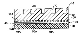
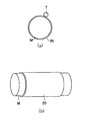
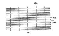
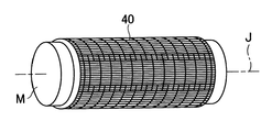
次に、本発明のシュープレスベルトの実施形態を図面に基づいて説明する。図1は本発明のシュープレスベルトの一部拡大断面図、図2(a)はシュー側層の形成過程を示すマンドレルの側面図、(b)は同斜視図、図3は本発明のシュープレスベルトを用いたシュープレス機構の斜視図、図4は基体に用いる格子状素材を説明するための一部平面図、図5はマンドレル表面に形成したシュー側層の外面に基体となる格子状素材を配置する過程を示す斜視図、図6は糸巻層を形成する過程を示す斜視図、図7は糸巻層形成後に接合する過程を示す斜視図である。 Next, an embodiment of the shoe press belt of the present invention will be described with reference to the drawings. 1 is a partially enlarged cross-sectional view of a shoe press belt of the present invention, FIG. 2 (a) is a side view of a mandrel showing a process of forming a shoe side layer, (b) is a perspective view thereof, and FIG. 3 is a shoe of the present invention. FIG. 4 is a partial plan view for explaining a grid-like material used for the base, and FIG. 5 is a grid-like form that becomes the base on the outer surface of the shoe side layer formed on the mandrel surface. FIG. 6 is a perspective view showing a process of arranging a material, FIG. 6 is a perspective view showing a process of forming a pincushion layer, and FIG. 7 is a perspective view showing a process of joining after forming the pincushion layer.
図1に示すように、本発明のシュープレス用ベルト10は、シュー側層20と、シュー側層20の外周に形成された基体30と、基体30の外周に形成された湿紙側層60とからなり、シュー側層20が表面が磨かれたマンドレル上で形成され、基体30が経糸40Aと緯糸40Bの交差部が接合されてなる格子状素材40と、糸50Aを螺旋状に巻き込んでなる糸巻層50とからなることを特徴とする。
As shown in FIG. 1, the
シュー側層20は、図2(b)に示すように、マンドレルMの磨かれた表面で形成される。この場合、マンドレルMの表面には予め剥離剤(図示せず。)を塗布するか、剥離シート(図示せず。)を貼着し、図2(a)に示すように、塗布機(ドクターバー又はコーターバー等)Tを用いて厚さ=0.5mm〜2.0mm程度に形成される。
The
本発明のシュープレスベルト10は、図3に示すように、シュープレス機構100のプレスロール102とシュー104との間に通されるため、本発明のシュープレスベルト10の最内層を構成するシュー側層20は、シュー104に強く接触した状態で常時滑走するので高い平滑性が要求される。この平滑性は前述のようにマンドレルMの磨かれた表面で確保されるから、平滑性を得るための後加工が不要となる。
As shown in FIG. 3, the
なお、マンドレルMの表面を磨いているのは、本発明のシュープレスベルト10の最内層の平滑性の確保のみならず、出来上がった本発明のシュープレスベルトの離脱性を良好にする意図もあることは勿論である。また、マンドレルMには加熱装置(図示せず。)が付属し、シュー側層20を含む樹脂の硬化を促進できるようになっている。
The surface of the mandrel M is polished not only to ensure the smoothness of the innermost layer of the
次に、シュー側層20の外周に、経糸40Aと緯糸40Bの交差部が接合されてなる格子状素材40と、糸50AをマンドレルMに対して螺旋状に巻き込んでなる糸巻層50とにより、基体30を形成する。
格子状素材40は、特開2002−194855号公報に開示されているもの等が使用できる。特に、本発明においては、例えば、図4に示すような、経糸40Aよりも強度が高い緯糸40Bにより糸40Aが挟まれ、経糸40Aと緯糸40Bの交差部の接合が樹脂接着や熱溶融処理等により行われてなる格子状素材40を用いることができる。
Next, on the outer periphery of the
As the lattice-
基体30の形成方法の一例を、図1及び図5乃至図7に基づいて説明する。
シュー側層20形成後、最初に、複数枚物の格子状素材40を、経糸40Aよりも強度が高い緯糸40BがマンドレルMの軸方向Jに沿うようにシュー側層20の外周に1層配置する。この際、マンドレルMの両端に設置されている格子状素材40を牽引及び固定するための装置(図示せず。)を使用して、複数枚物の格子状素材40を其々均一な張力の下に牽引し固定することができる。
ここで、経糸40Aより強度の高い緯糸40BをマンドレルMの軸方向に沿わせたのは、本発明のシュープレスベルト10に幅方向(CMD方向)の強度と寸法安定性を付与するためである。
なお、ここでは格子状素材40が、経糸40Aとそれよりも強度が高い緯糸40Bとからなる格子状素材を説明してきたが、経糸40Aと緯糸40Bとが同等の強度からなる糸であって、然も格子状素材を構成する糸本数(メッシュ;本数/cm)において前記緯糸本数が前記経糸本数より2倍以上多い格子状素材を使用することができる。
An example of a method for forming the
After the shoe-
Here, the reason why the
Here, the lattice-
また、ベルトの強度向上のために、複数枚物の格子状素材40をマンドレルMの軸方向に沿わせて、その幅方向の端部が重なり合うように配置することが好ましい。なお、このように幅方向の端部を重ね合わせても、格子状素材40は、織布と違って経糸と緯糸による屈曲がないので、ベルト使用時、樹脂層にクラックが生じることはない。
Further, in order to improve the strength of the belt, it is preferable that the plurality of lattice-
格子状素材40は、図4に示すような複数枚物でなく、1枚物で構成することも可能であるが、マンドレルMの両端に設置されている格子状素材40の牽引及び固定するための装置(図示せず。)を効果的に使用して、格子状素材40を均一な張力の下に牽引し固定するためには、複数枚物を使う方が好ましく然も格子状素材40を簡便に配置できる。
また、格子状素材40は、マンドレルMの軸方向に沿って配置するものに限るものではなく、例えば、シュー側層20に対して螺旋状に巻き込むように配置することもできる。この場合も、ベルトの強度向上のために、格子状素材40の幅方向の端部同士が重なり合うように配置することが好ましい。
The lattice-
Further, the lattice-shaped
次に、格子状素材40の外周に、糸50Aを螺旋状に巻き込んでなる糸巻層50を形成する。この糸巻層50は、図6に示すように、糸50Aを保有する糸供給装置(図示せず。)に組込まれたボビンBoから引き出された糸を、マンドレルMを回転させながら基体30の周囲に全域にわたって螺旋状に糸50Aを巻き込んで行く。このとき、ボビンBoを複数用いて複数条に巻いて行く場合もある。
糸供給装置は、糸50Aを螺旋状に巻込んでなる糸巻層50を形成しながら、それに連動してマンドレルMの軸方向に沿って移動するための移動装置をも具備している。
この糸巻層50は、本発明のシュープレスベルト10にMD方向の強度を付与するのに効果がある。
Next, the
The yarn supply device also includes a moving device for moving along the axial direction of the mandrel M in conjunction with the formation of the
This
糸巻層50形成後、図7に示すように、マンドレルMを回転させながら、格子状素材40と糸巻層50の隙間を塞ぐ程度に上から樹脂を塗布し、基体30を一体化する。これにより、基体30が完成する。
このときの樹脂は、格子状素材40と糸巻層50の隙間に浸透しやすい粘度となる温度に加熱されていることが好ましい。
After forming the
The resin at this time is preferably heated to a temperature at which the viscosity easily penetrates into the gap between the
これまで、シュープレスベルトの基体30の成形は、シュー側層20の外周に格子状素材40を1層配置し、その外周に糸巻層50を形成するものとして説明してきたが、格子状素材40と糸巻層50の配置形態はこれに限るものではない。
例えば、(1)先に糸巻層50を形成し、次に格子状素材40を配置したり、(2)格子状素材40を複数層配置したり、(3)先に糸巻層50を形成し、次に格子状素材40を配置した後、さらに、糸巻層50を形成したり、(4)先に格子状素材40を配置し、次に糸巻層50を形成した後、さらに、格子状素材40を配置して糸巻層50を形成すること等、様々な形態が可能である。
なお、格子状素材40を複数層配置する場合、或る層の幅方向の端部の重なり部分が、他の層の幅方向の端部の重なり部分と重ならないように配置することが好ましい。
Up to now, the formation of the
For example, (1) the
In the case where a plurality of layers of the lattice-
さらにその後、前記糸巻層50の外周に無端状の湿紙側層60を形成する。湿紙側層60を形成する樹脂は、格子状素材40と糸巻層50とからなる基体30を通過して含浸し、シュー側層20の外面と接合して一体化する。シュー側層20と湿紙側層60との接合面は、通常、自然に、互いに接合一体化するが、必要に応じて、プライマや接着剤を用いて一体化の程度を向上させてもよい。
Thereafter, an endless wet
前記シュー側層20及び湿紙側層60に使用される樹脂は、ゴム、エラストマーの中から選択できるが、好ましくはポリウレタン樹脂が使用される。ポリウレタン樹脂としては、その物性面からすると熱硬化性ウレタン樹脂が好ましく、硬度80〜98°(JIS−A)の範囲で選択するとよい。勿論、シュー側層20と湿紙側層60との硬度は同じでも異なっていてもよい。
The resin used for the
前記基体30として使用する格子状素材40に用いた緯糸40Bは、前述のように、本発明のシュープレスベルト10に幅方向(CMD方向)の強度を付与するために、図4に示すような、比較的太く剛直な糸、例えば、500〜10000デシテックス相当のモノフィラメント糸やマルチフィラメント糸又はこれらの撚糸を用い、これに交差する糸は緯糸40Bの間隔がずれないように支持できれば足りる。
As described above, the
前記格子状素材40に用いる緯糸40Bの素材は、ベルト使用時の耐久性や寸法安定性のみならず、マンドレルから本発明のシュープレスベルト10を離脱させる際の牽引力に対する耐久性や離脱を容易にするために、ナイロン、PET、芳香族ポリアミド、芳香族ポリイミド、高強度ポリエチレン等の高いモジュラス、高弾性率の合成繊維がよい。そして、前記格子状素材40の緯糸40Bが形成する格子の強度が50〜250kg/cm、1%モジュラスが5〜40kg/cmの範囲にあることが好ましい。また、炭素繊維やガラス繊維等の無機繊維を使用することも可能である。
The material of the
前記格子状素材40を、前記シュー側層20の外周に配置するに際し、シュー側層20の硬化前(未だ可膠性を保持する間)に、前記マンドレルMを少しずつ回転させ、緯糸40BがマンドレルMの軸方向に沿うようにして配置する。このとき、マンドレルMの両端に設置されている格子状素材40を牽引及び固定するための装置(図示せず。)を使用する。それにより複数枚物の格子状素材40は、個々に掴み部材にて掴まれ、均一な張力の下に牽引されつつ固定される。
When the lattice-
上記場合、格子状素材40が1枚物のときは、その寸法をシュー側層20の円周寸法に対して100%以上に調整して1周り廻して幅方向端部が重なり合うように被せる。また、格子状素材40が複数枚物のときは、互いの幅方向の端部が重なり合うように注意することが肝要である。
なお、「端部が重なり合う」というのは、文字通り、上下に重なり合う場合だけでなく、隣合う格子状素材から対向して突出している糸同士が、当該糸を、格子状素材がなす面に沿って直角方向に見たとき重なり合っている場合も含むものとする。
In the above case, when the lattice-
Note that “ends overlap” literally means not only the case where they overlap vertically, but also the yarns that project opposite to each other from the adjacent lattice-like material, along the surface formed by the lattice-like material. This also includes the case where they overlap when viewed in a right angle direction.
前記糸巻層50に用いる糸50Aの素材は、前記格子状素材40の緯糸40Bと同様にナイロン、PET、芳香族ポリアミド、芳香族ポリイミド、高強度ポリエチレン等の高強力、高モジュラス、高弾性率の合成繊維からなるモノフィラメント糸やマルチフィラメント糸又はこれらの撚糸が用いられる。
The material of the
前記糸50AはナイロンやPETのマルチフィラメント(7000dtex)では10本〜50本/5cmで巻き込み、また、芳香族ポリアミドからなるマルチフィラメント(3000dtex)では10本〜30本/5cmで巻き込んで、最終製品の強度が100〜300kg/cmになるように製造することが望ましい。
The
前記湿紙側層60の形成は、糸50Aを巻き込んで糸巻層50を形成させた後でもよいが、糸50Aの巻き込みと並行して進めることもできる。この湿紙側層60を形成後、マンドレルMに付属している加熱装置によって樹脂を加熱硬化させ、さらに本発明のシュープレスベルト10の目標の厚みに表面を研磨し、必要に応じて表面に凹溝(盲孔でもよい。)70の仕上げ加工を行い、本発明のシュープレスベルト10を得る。
The wet paper
しかる後、前記マンドレルMから本発明のシュープレスベルト10を離脱させる。この離脱は、前述のように、マンドレルM表面に予め剥離材や剥離シートを使用しておき、図8に示すように、ベルト10の一方の端部をマンドレルMより径の大きなリングRに連結し、エア圧、水圧、油圧、又は樹脂の膨張収縮を利用して、リングRをマンドレルMから離すことで、簡易に行われる。
従来、このシュープレスベルト成形後の離脱はマンドレルMとほぼ同一径のリングを使用していたがスムーズに離脱できなかった。それはマンドレルMの周端部でのシュープレスベルトとの摩擦が非常に強いことが考慮されていなかったためで、本発明においては、ベルト10の一方の端部をマンドレルMより径の大きなリングRに固定し、リングRをマンドレルMから離すことで、離脱を簡易に行うことが可能になった。
Thereafter, the
Conventionally, the ring after forming the shoe press belt has used a ring having almost the same diameter as the mandrel M, but could not be removed smoothly. This is because it was not considered that the friction with the shoe press belt at the peripheral end of the mandrel M was very strong. In the present invention, one end of the
上記構成による本発明のシュープレスベルトについて、具体的に以下に示す工程により実施例1乃至10及び比較例1を作製した。
(実施例1)
工程1:適宜駆動手段により回転可能な直径1500mmのマンドレルの磨かれた表面に剥離剤(KS−61:信越化学工業製)を塗布した。次に、マンドレルを回転させながら、マンドレル表面に熱硬化性ウレタン樹脂(TDI系プレポリマー(タケネートL2395[武田製薬製])とDMTDAを含有する硬化剤(ETHACURE300[アルベマール社製])とを、H/NCO当量比が0.97となるように混合したもの)をドクターバーを用いて1mm厚みに塗布し、マンドレルを回転させたまま室温で10分間放置し、さらに、マンドレルに付属している加熱装置によって樹脂を70℃で30分間加熱し硬化させた。なお、ETHACURE300は、3,5−ジメチルチオ2,4−トルンジアミンと、3,5−ジメチルチオ2,6−トルンジアミンとの混合物である。
With respect to the shoe press belt of the present invention having the above-described configuration, Examples 1 to 10 and Comparative Example 1 were produced by the following specific steps.
Example 1
Step 1: A release agent (KS-61: manufactured by Shin-Etsu Chemical Co., Ltd.) was applied to a polished surface of a mandrel having a diameter of 1500 mm that can be appropriately rotated by a driving means. Next, while rotating the mandrel, a thermosetting urethane resin (TDI-based prepolymer (Takenate L2395 [manufactured by Takeda Pharmaceutical]) and a hardener (ETHACURE300 [manufactured by Albemarle]) containing DMTDA on the mandrel surface, / NCO equivalence ratio is 0.97) using a doctor bar, apply to a thickness of 1 mm, leave the mandrel rotating for 10 minutes at room temperature, and then heat the mandrel. The resin was cured by heating at 70 ° C. for 30 minutes using an apparatus. ETHACURE 300 is a mixture of 3,5-dimethylthio-2,4-torundiamine and 3,5-dimethylthio-2,6-torundiamine.
工程2:PET繊維の5000dtexのマルチフィラメント糸の撚糸を経糸及び緯糸として、経糸が緯糸で挟まれ、緯糸と経糸の交差部がウレタン系樹脂接着により接合されてなる格子状素材(緯糸密度は表1に記載。経糸密度は全実施例共通で1本/cmとした。)を用意した。複数枚物の格子状素材を、緯糸がマンドレルの軸方向に沿い、幅方向の端部が重なり合うように、シュー側層の外周に1層配置した。そして、この格子状素材の外周に、PET繊維の7000dtexのマルチフィラメント糸を螺旋状に表1に記載したピッチで巻き付けて、糸巻層を形成した。その後、格子状素材と糸巻層の隙間を塞ぐ程度に樹脂を塗り一体化して、基体を形成した。 Process 2: A lattice-like material in which a 5000 dtex multifilament yarn of PET fiber is used as a warp and a weft, the warp is sandwiched between the wefts, and the intersection of the weft and the warp is joined by urethane-based resin adhesion (the weft density is represented by The warp density was 1 / cm common to all examples. A plurality of lattice-like materials were arranged on the outer periphery of the shoe side layer so that the wefts were along the axial direction of the mandrel and the end portions in the width direction were overlapped. Then, a 7000 dtex multifilament yarn of PET fiber was spirally wound around the outer periphery of the lattice material at a pitch described in Table 1 to form a bobbin layer. Thereafter, resin was applied and integrated so as to block the gap between the lattice material and the pincushion layer to form a substrate.
工程3:糸巻層の上から、前記シュー側層に用いた樹脂と同じ熱硬化性ウレタン樹脂を、5.5mm厚に含浸コートし、100℃で5時間加熱硬化させた後、湿紙側層の表面を研磨して全厚が5.0mm厚になるようにしてから、回転刃でベルトのMD方向に凹溝を形成して本発明のシュープレスベルトを得た。 Step 3: From the top of the pincushion layer, the same thermosetting urethane resin as the resin used for the shoe side layer is impregnated to a thickness of 5.5 mm, heated and cured at 100 ° C. for 5 hours, and then the wet paper web side layer. After the surface was polished to a total thickness of 5.0 mm, a groove was formed in the MD direction of the belt with a rotary blade to obtain a shoe press belt of the present invention.
(実施例2)
工程2において、シュー側層の外周に、糸巻層を形成した後、その外周に、緯糸がマンドレルの軸方向に沿い、幅方向の端部が重なり合うように複数枚物の格子状素材を1層配置し、基体を形成した。
(実施例3)
工程2において、シュー側層の外周に、緯糸がマンドレルの軸方向に沿い、一方の層の幅方向の端部の重なり部分が、他の層の幅方向の端部の重なり部分と重ならないように幅方向の端部を重ね合わせ、複数枚物の格子状素材を2層配置した後、その外周に、糸巻層を形成し、基体を形成した。
(実施例4)
工程2において、シュー側層の外周に、糸巻層を形成した後、その外周に、緯糸がマンドレルの軸方向に沿い、一方の層の幅方向の端部の重なり部分が、他の層の幅方向の端部の重なり部分と重ならないように幅方向の端部を重ね合わせ、複数枚物の格子状素材を2層配置し、基体を形成した。
(Example 2)
In step 2, after forming a wound layer on the outer periphery of the shoe side layer, one layer of a plurality of lattice-like materials is formed on the outer periphery so that the wefts are along the mandrel axial direction and the end portions in the width direction overlap. Arranged and formed a substrate.
(Example 3)
In step 2, the wefts run along the axial direction of the mandrel on the outer periphery of the shoe side layer so that the overlapping portion of the end portion in the width direction of one layer does not overlap the overlapping portion of the end portion in the width direction of the other layer. The end portions in the width direction were superposed on each other, and two layers of a plurality of lattice-like materials were arranged, and then a bobbin layer was formed on the outer periphery to form a substrate.
Example 4
In step 2, after forming the wound layer on the outer periphery of the shoe side layer, the overlap of the end portion in the width direction of one layer is the width of the other layer on the outer periphery along the axial direction of the mandrel. The end portions in the width direction were overlapped so as not to overlap with the overlapping portions of the end portions in the direction, and two layers of lattice-like materials were arranged to form a substrate.
(実施例5)
工程2において、シュー側層の外周に、螺旋状に巻き込み、幅方向の端部が重なり合うように1枚物の格子状素材1層配置した後、その外周に、糸巻層を形成し、基体を形成した。
(実施例6)
工程2において、シュー側層の外周に、糸巻層を形成した後、その外周に、螺旋状に巻き込み、幅方向の端部が重なり合うように1枚物の格子状素材を1層配置し、基体を形成した。
(実施例7)
工程2において、シュー側層の外周に、螺旋状に巻き込み、幅方向の端部が重なり合うように1枚物の格子状素材を1層配置し、さらに逆向きに、螺旋状に巻き込み、幅方向の端部が重なり合うように格子状素材をもう1層配置し、その外周に、糸巻層を形成し、基体を形成した。
(Example 5)
In step 2, after winding around the outer periphery of the shoe-side layer in a spiral manner and arranging one layer of lattice-like material so that the ends in the width direction overlap, a pincushion layer is formed on the outer periphery, Formed.
(Example 6)
In step 2, after forming a pincushion layer on the outer periphery of the shoe side layer, it is spirally wound around the outer periphery, and a single layer of a grid-like material is disposed so that the ends in the width direction overlap each other, Formed.
(Example 7)
In step 2, the shoe-side layer is spirally wound on the outer periphery, one layer of the lattice material is disposed so that the end portions in the width direction are overlapped, and further spirally wound in the opposite direction. Another layer of the lattice-like material was disposed so that the ends of the two layers overlapped, and a bobbin layer was formed on the outer periphery to form a substrate.
(実施例8)
工程2において、シュー側層の外周に、糸巻層を形成した後、その外周に、螺旋状に巻き込み、幅方向の端部が重なり合うように1枚物の格子状素材を1層配置し、さらに逆向きに、螺旋状に巻き込み、幅方向の端部が重なり合うように格子状素材をもう1層配置し、基体を形成した。
(実施例9)
工程2において、シュー側層の外周に、糸巻層を形成した後、その外周に、緯糸がマンドレルの軸方向に沿い、幅方向の端部が重なり合うように複数枚物の格子状素材を1層配置し、さらにその外周に糸巻層を形成し、基体を形成した。
(実施例10)
工程2において、シュー側層の外周に、緯糸がマンドレルの軸方向に沿い、幅方向の端部が重なり合うように格子状素材を1周配置した後、その外周に、糸巻層を形成し、さらにその外周に、緯糸がマンドレルの軸方向に沿い、下の格子状素材の幅方向の端部の重なり部分と重ならないように幅方向の端部を重ね合わせ、格子状素材を1周配置し、さらにその外周に糸巻層を形成し、基体を形成した。
(Example 8)
In step 2, after forming the pincushion layer on the outer periphery of the shoe side layer, it is spirally wound around the outer periphery, and one layer of the lattice-like material is arranged so that the end portions in the width direction overlap each other. In reverse, the substrate was wound in a spiral shape and another layer of the lattice-like material was disposed so that the end portions in the width direction overlapped to form a substrate.
Example 9
In step 2, after forming a wound layer on the outer periphery of the shoe side layer, one layer of a plurality of lattice-like materials is formed on the outer periphery so that the wefts are along the mandrel axial direction and the end portions in the width direction overlap. Then, a bobbin layer was formed on the outer periphery to form a substrate.
(Example 10)
In step 2, after arranging the lattice-shaped material once around the outer periphery of the shoe side layer so that the wefts are along the axial direction of the mandrel and the ends in the width direction overlap, a wound layer is formed on the outer periphery; Over the outer periphery, the wefts are along the mandrel axial direction, and the widthwise ends are overlapped so that they do not overlap the widthwise ends of the underlying grid-like material, and the grid-like material is placed once, Further, a bobbin layer was formed on the outer periphery to form a substrate.
(比較例1)
図10に示すように、二本のロールA、B間に無端織物Cを掛けわたし、織物Cの表面に、塗布機Dにより実施例1と同じ熱硬化性ウレタン樹脂を含浸塗布して加熱硬化させた。その樹脂の外周を研磨してシュー側層Eを形成した。
次いで、シュー側層Eが内側、無端織物が外側となるように反転させ、その織物の外周にシュー側層に用いた樹脂と同じ熱硬化性ウレタン樹脂を含浸塗布して100℃で5時間加熱硬化させて湿紙側層Fを形成し、湿紙側層Fを研磨して全厚を5.0mm厚にしてから、回転刃でベルトのMD方向に凹溝Gを形成して比較例1を得た。
(Comparative Example 1)
As shown in FIG. 10, an endless woven fabric C is hung between two rolls A and B, and the surface of the woven fabric C is impregnated with the same thermosetting urethane resin as in Example 1 by a coating machine D and heat-cured. I let you. The shoe outer layer E was formed by polishing the outer periphery of the resin.
Next, the shoe side layer E is turned inside so that the endless fabric is turned outside, and the outer periphery of the fabric is impregnated with the same thermosetting urethane resin used for the shoe side layer and heated at 100 ° C. for 5 hours. The wet paper web side layer F is cured to be cured, the wet paper web side layer F is polished to a total thickness of 5.0 mm, and then a concave groove G is formed in the MD direction of the belt with a rotary blade. Got.
上記実施例1乃至10と比較例1について、切断強度、耐クラック性等の物性を調べた。
耐クラック性を調べるために使用した装置を、図9に示す。この装置は、実験片13の両端が、クランプハンドCH、CHにより挟持され、クランプハンドCH、CHが、連動して左右方向に往復移動可能に構成されている。実験片13における評価面は、回転ロールRR1側に向けられており、プレスシューPSが回転ロールRR1方向に移動することにより、実験片13は加圧される。この装置により、クラックが生じるまでの往復回数を測定し、シュープレスベルトの耐クラック性を調べた。
なお、この際、実験片13に掛けられる張力は3kg/cm、圧力は36kg/cm2、往復速度は40cm/秒である。
Regarding Examples 1 to 10 and Comparative Example 1, physical properties such as cutting strength and crack resistance were examined.
The apparatus used for examining the crack resistance is shown in FIG. In this apparatus, both ends of the
At this time, the tension applied to the
実施例1乃至10と比較例1の切断強度、耐クラック性等の物性を表1に示す。

表1より本発明の実施例は、特に、耐クラック性が比較例に比して優れていることが分かる。
このように、実施例が耐クラック性に優れているのは、比較例の基体は経糸と緯糸による屈曲がある織布からなるため、ベルト使用時における交差部への応力集中によりクラックが発生しやすいのに対し、実施例は、経糸と緯糸の交差部が接合されてなり、経糸と緯糸による屈曲がない格子状素材を基体の構成要素に用いているので、ベルト使用時の樹脂層でのクラックが発生しにくいためと理解される。
From Table 1, it can be seen that the examples of the present invention are particularly excellent in crack resistance as compared with the comparative examples.
In this way, the example is excellent in crack resistance because the substrate of the comparative example is made of a woven fabric that is bent by warps and wefts, so that cracks occur due to stress concentration at the intersection when using the belt. On the other hand, in the example, the intersection of the warp and the weft is joined, and a lattice-like material that is not bent by the warp and the weft is used as a component of the base. It is understood that cracks are unlikely to occur.
以上説明したように、本発明によれば、経糸と緯糸の交差部が接合されてなり、経糸と緯糸による屈曲がない格子状素材を基体の構成要素に用いることにより、ベルト使用時の樹脂層でのクラックの発生を防ぎ、耐久性を向上させることができる。
また、基体形成のために、糸をマンドレルの軸方向に張る必要がないだけでなく、経糸と緯糸の交差部が接合されているため、マンドレルに巻きつける際に織目のずれを修正する必要がないので、生産性が格段に向上するという効果を奏する。
As described above, according to the present invention, a resin layer at the time of use of the belt can be obtained by using, as a constituent element of the base, a lattice-like material in which the intersecting portion of the warp and the weft is joined and is not bent by the warp and the weft. It is possible to prevent the occurrence of cracks and improve the durability.
In addition, it is not necessary to stretch the yarn in the axial direction of the mandrel for forming the base body, and since the intersecting portion of the warp and weft is joined, it is necessary to correct the deviation of the texture when winding on the mandrel As a result, there is an effect that productivity is remarkably improved.
10:シュープレスベルト
20:シュー側層
30:基体
40:格子状素材
40A:経糸
40B:緯糸
50:糸巻層
50A:糸
60:湿紙側層
M:マンドレル
10: Shoe press belt 20: Shoe side layer 30: Substrate 40:
Claims (5)
前記シュー側層が表面が磨かれたマンドレル上で形成されたものであり、前記基体が、経糸が緯糸で挟まれ、経糸と緯糸の交差部が接合されてなる格子状素材と、螺旋状に巻き込まれた糸巻層とからなることを特徴とする、
シュープレス用ベルト。 In the shoe press belt, which is disposed between the press roll and the shoe of the shoe press device, and includes a base, a wet paper web side layer, and a shoe side layer,
The shoe side layer is formed on a mandrel whose surface is polished, and the base is spirally formed with a lattice-like material in which a warp is sandwiched between wefts and an intersection of warp and weft is joined. It is composed of a wound spool layer,
Shoe press belt.
The shoe press belt according to any one of claims 1 to 4, wherein the lattice-shaped materials are arranged so that end portions in the width direction overlap each other.
Priority Applications (1)
| Application Number | Priority Date | Filing Date | Title |
|---|---|---|---|
| JP2005076216A JP4593326B2 (en) | 2004-03-26 | 2005-03-17 | Shoe press belt |
Applications Claiming Priority (2)
| Application Number | Priority Date | Filing Date | Title |
|---|---|---|---|
| JP2004091505 | 2004-03-26 | ||
| JP2005076216A JP4593326B2 (en) | 2004-03-26 | 2005-03-17 | Shoe press belt |
Publications (3)
| Publication Number | Publication Date |
|---|---|
| JP2005307421A JP2005307421A (en) | 2005-11-04 |
| JP2005307421A5 JP2005307421A5 (en) | 2007-12-06 |
| JP4593326B2 true JP4593326B2 (en) | 2010-12-08 |
Family
ID=35436507
Family Applications (1)
| Application Number | Title | Priority Date | Filing Date |
|---|---|---|---|
| JP2005076216A Active JP4593326B2 (en) | 2004-03-26 | 2005-03-17 | Shoe press belt |
Country Status (1)
| Country | Link |
|---|---|
| JP (1) | JP4593326B2 (en) |
Families Citing this family (7)
| Publication number | Priority date | Publication date | Assignee | Title |
|---|---|---|---|---|
| JP4524233B2 (en) * | 2005-09-22 | 2010-08-11 | イチカワ株式会社 | Shoe press belt |
| AU2006319944A1 (en) * | 2005-11-30 | 2007-06-07 | Yamauchi Corporation | Press belt |
| JP4856475B2 (en) | 2006-06-05 | 2012-01-18 | イチカワ株式会社 | Shoe press belt |
| JP4516583B2 (en) | 2007-05-18 | 2010-08-04 | イチカワ株式会社 | Shoe press belt |
| KR101075479B1 (en) | 2007-06-25 | 2011-10-21 | 이치가와 가부시키가이샤 | Shoe press belt for paper making |
| JP4516610B2 (en) | 2008-02-08 | 2010-08-04 | イチカワ株式会社 | Shoe press belt |
| JP4444367B1 (en) | 2009-07-21 | 2010-03-31 | イチカワ株式会社 | Shoe press belt for papermaking |
Citations (6)
| Publication number | Priority date | Publication date | Assignee | Title |
|---|---|---|---|---|
| JPH05505428A (en) * | 1990-07-31 | 1993-08-12 | ベロイト・テクノロジーズ・インコーポレイテッド | Wide nip press blanket with anisotropic woven base |
| JPH1121781A (en) * | 1997-07-03 | 1999-01-26 | Ichikawa Woolen Textile Co Ltd | Shoe press belt and its production |
| JPH11247086A (en) * | 1998-02-26 | 1999-09-14 | Ichikawa Woolen Textile Co Ltd | Shoe press belt and its production |
| JP2000027089A (en) * | 1998-04-02 | 2000-01-25 | Thomas Josef Heimbach Gmbh & Co | Belt body, its production, and device for producing the same |
| JP2004513253A (en) * | 2000-11-03 | 2004-04-30 | アルバニー インターナショナル コーポレイション | Long nip shoe press belt with groove |
| JP2004521195A (en) * | 2001-01-26 | 2004-07-15 | アルバニー インターナショナル コーポレイション | Spiral wound forming yarn and industrial belt for paper machine cover |
-
2005
- 2005-03-17 JP JP2005076216A patent/JP4593326B2/en active Active
Patent Citations (7)
| Publication number | Priority date | Publication date | Assignee | Title |
|---|---|---|---|---|
| JPH05505428A (en) * | 1990-07-31 | 1993-08-12 | ベロイト・テクノロジーズ・インコーポレイテッド | Wide nip press blanket with anisotropic woven base |
| JPH1121781A (en) * | 1997-07-03 | 1999-01-26 | Ichikawa Woolen Textile Co Ltd | Shoe press belt and its production |
| JPH11247086A (en) * | 1998-02-26 | 1999-09-14 | Ichikawa Woolen Textile Co Ltd | Shoe press belt and its production |
| JP3408416B2 (en) * | 1998-02-26 | 2003-05-19 | 市川毛織株式会社 | Shoe press belt and method of manufacturing the same |
| JP2000027089A (en) * | 1998-04-02 | 2000-01-25 | Thomas Josef Heimbach Gmbh & Co | Belt body, its production, and device for producing the same |
| JP2004513253A (en) * | 2000-11-03 | 2004-04-30 | アルバニー インターナショナル コーポレイション | Long nip shoe press belt with groove |
| JP2004521195A (en) * | 2001-01-26 | 2004-07-15 | アルバニー インターナショナル コーポレイション | Spiral wound forming yarn and industrial belt for paper machine cover |
Also Published As
| Publication number | Publication date |
|---|---|
| JP2005307421A (en) | 2005-11-04 |
Similar Documents
| Publication | Publication Date | Title |
|---|---|---|
| KR101106847B1 (en) | Shoe press belt | |
| JP4593326B2 (en) | Shoe press belt | |
| JP3408416B2 (en) | Shoe press belt and method of manufacturing the same | |
| KR0167087B1 (en) | A blanket for an extended nip press with anisotropic woven base layers | |
| JP3096127B2 (en) | Long nip press belt | |
| US5968318A (en) | Shoe press belt and manufacturing method therefor | |
| JP3917358B2 (en) | Endless woven and needle-perforated cardboard belt | |
| NO304277B1 (en) | Final belt for dewatering press and method of manufacture thereof | |
| TW201723248A (en) | Textile machine belt | |
| JP3488397B2 (en) | Shoe press belt and method of manufacturing the same | |
| EP2028317B1 (en) | Belt for shoe press | |
| JP2007524768A (en) | Base material for endless belts used in paper machines | |
| JP4524233B2 (en) | Shoe press belt | |
| JP3415793B2 (en) | Shoe press belt and method of manufacturing the same | |
| TW201805150A (en) | Self-tensioning drum covering for a drive drum in a corrugating machine | |
| JP2008150739A (en) | Shoe press belt | |
| JP3415767B2 (en) | Shoe press belt and method of manufacturing the same | |
| EP1504156A1 (en) | Belt for a shoe press and method for forming same |
Legal Events
| Date | Code | Title | Description |
|---|---|---|---|
| A521 | Request for written amendment filed |
Free format text: JAPANESE INTERMEDIATE CODE: A523 Effective date: 20071019 |
|
| A621 | Written request for application examination |
Free format text: JAPANESE INTERMEDIATE CODE: A621 Effective date: 20071019 |
|
| A977 | Report on retrieval |
Free format text: JAPANESE INTERMEDIATE CODE: A971007 Effective date: 20100202 |
|
| A131 | Notification of reasons for refusal |
Free format text: JAPANESE INTERMEDIATE CODE: A131 Effective date: 20100420 |
|
| A521 | Request for written amendment filed |
Free format text: JAPANESE INTERMEDIATE CODE: A523 Effective date: 20100611 |
|
| TRDD | Decision of grant or rejection written | ||
| A01 | Written decision to grant a patent or to grant a registration (utility model) |
Free format text: JAPANESE INTERMEDIATE CODE: A01 Effective date: 20100817 |
|
| A01 | Written decision to grant a patent or to grant a registration (utility model) |
Free format text: JAPANESE INTERMEDIATE CODE: A01 |
|
| A61 | First payment of annual fees (during grant procedure) |
Free format text: JAPANESE INTERMEDIATE CODE: A61 Effective date: 20100915 |
|
| FPAY | Renewal fee payment (event date is renewal date of database) |
Free format text: PAYMENT UNTIL: 20130924 Year of fee payment: 3 |
|
| R150 | Certificate of patent or registration of utility model |
Ref document number: 4593326 Country of ref document: JP Free format text: JAPANESE INTERMEDIATE CODE: R150 Free format text: JAPANESE INTERMEDIATE CODE: R150 |
|
| R250 | Receipt of annual fees |
Free format text: JAPANESE INTERMEDIATE CODE: R250 |
|
| R250 | Receipt of annual fees |
Free format text: JAPANESE INTERMEDIATE CODE: R250 |
|
| R250 | Receipt of annual fees |
Free format text: JAPANESE INTERMEDIATE CODE: R250 |
|
| R250 | Receipt of annual fees |
Free format text: JAPANESE INTERMEDIATE CODE: R250 |
|
| R250 | Receipt of annual fees |
Free format text: JAPANESE INTERMEDIATE CODE: R250 |
|
| R250 | Receipt of annual fees |
Free format text: JAPANESE INTERMEDIATE CODE: R250 |
|
| R250 | Receipt of annual fees |
Free format text: JAPANESE INTERMEDIATE CODE: R250 |
|
| R250 | Receipt of annual fees |
Free format text: JAPANESE INTERMEDIATE CODE: R250 |
|
| R250 | Receipt of annual fees |
Free format text: JAPANESE INTERMEDIATE CODE: R250 |
|
| R250 | Receipt of annual fees |
Free format text: JAPANESE INTERMEDIATE CODE: R250 |
|
| R250 | Receipt of annual fees |
Free format text: JAPANESE INTERMEDIATE CODE: R250 |
|
| R250 | Receipt of annual fees |
Free format text: JAPANESE INTERMEDIATE CODE: R250 |