EP2452847A1 - Driving device utilizing inertia - Google Patents
Driving device utilizing inertia Download PDFInfo
- Publication number
- EP2452847A1 EP2452847A1 EP10191135A EP10191135A EP2452847A1 EP 2452847 A1 EP2452847 A1 EP 2452847A1 EP 10191135 A EP10191135 A EP 10191135A EP 10191135 A EP10191135 A EP 10191135A EP 2452847 A1 EP2452847 A1 EP 2452847A1
- Authority
- EP
- European Patent Office
- Prior art keywords
- flywheel
- motor
- generator
- battery
- driving device
- Prior art date
- Legal status (The legal status is an assumption and is not a legal conclusion. Google has not performed a legal analysis and makes no representation as to the accuracy of the status listed.)
- Withdrawn
Links
Images
Classifications
-
- H—ELECTRICITY
- H02—GENERATION; CONVERSION OR DISTRIBUTION OF ELECTRIC POWER
- H02K—DYNAMO-ELECTRIC MACHINES
- H02K53/00—Alleged dynamo-electric perpetua mobilia
-
- B—PERFORMING OPERATIONS; TRANSPORTING
- B60—VEHICLES IN GENERAL
- B60L—PROPULSION OF ELECTRICALLY-PROPELLED VEHICLES; SUPPLYING ELECTRIC POWER FOR AUXILIARY EQUIPMENT OF ELECTRICALLY-PROPELLED VEHICLES; ELECTRODYNAMIC BRAKE SYSTEMS FOR VEHICLES IN GENERAL; MAGNETIC SUSPENSION OR LEVITATION FOR VEHICLES; MONITORING OPERATING VARIABLES OF ELECTRICALLY-PROPELLED VEHICLES; ELECTRIC SAFETY DEVICES FOR ELECTRICALLY-PROPELLED VEHICLES
- B60L50/00—Electric propulsion with power supplied within the vehicle
- B60L50/30—Electric propulsion with power supplied within the vehicle using propulsion power stored mechanically, e.g. in fly-wheels
-
- Y—GENERAL TAGGING OF NEW TECHNOLOGICAL DEVELOPMENTS; GENERAL TAGGING OF CROSS-SECTIONAL TECHNOLOGIES SPANNING OVER SEVERAL SECTIONS OF THE IPC; TECHNICAL SUBJECTS COVERED BY FORMER USPC CROSS-REFERENCE ART COLLECTIONS [XRACs] AND DIGESTS
- Y02—TECHNOLOGIES OR APPLICATIONS FOR MITIGATION OR ADAPTATION AGAINST CLIMATE CHANGE
- Y02T—CLIMATE CHANGE MITIGATION TECHNOLOGIES RELATED TO TRANSPORTATION
- Y02T10/00—Road transport of goods or passengers
- Y02T10/60—Other road transportation technologies with climate change mitigation effect
- Y02T10/64—Electric machine technologies in electromobility
-
- Y—GENERAL TAGGING OF NEW TECHNOLOGICAL DEVELOPMENTS; GENERAL TAGGING OF CROSS-SECTIONAL TECHNOLOGIES SPANNING OVER SEVERAL SECTIONS OF THE IPC; TECHNICAL SUBJECTS COVERED BY FORMER USPC CROSS-REFERENCE ART COLLECTIONS [XRACs] AND DIGESTS
- Y02—TECHNOLOGIES OR APPLICATIONS FOR MITIGATION OR ADAPTATION AGAINST CLIMATE CHANGE
- Y02T—CLIMATE CHANGE MITIGATION TECHNOLOGIES RELATED TO TRANSPORTATION
- Y02T10/00—Road transport of goods or passengers
- Y02T10/60—Other road transportation technologies with climate change mitigation effect
- Y02T10/70—Energy storage systems for electromobility, e.g. batteries
Landscapes
- Engineering & Computer Science (AREA)
- Power Engineering (AREA)
- Transportation (AREA)
- Mechanical Engineering (AREA)
- Electric Propulsion And Braking For Vehicles (AREA)
- Connection Of Motors, Electrical Generators, Mechanical Devices, And The Like (AREA)
Abstract
The driving device utilizing inertia mainly contains a battery (10), a motor (20), a flywheel (30), a casing (40), a transmission box (50), a generator (60), a rectifier (70), and a charger (80). The flywheel (30) is mounted on a shaft and is housed in a vacuum chamber. The flywheel (30) freely spins by itself after being actuated by the motor (20). The flywheel (30)'s torque is then delivered to the transmission box (50) which in turn delivers the torque to drive a vehicle. On the other hand, the spinning flywheel (30) drives the generator (60) to produce electricity which is stored in the battery (10) series-connected to the generator (60) via the rectifier (70) and the charger (80). As such, the driving device is able to power the vehicle while the surplus energy is stored in the battery (10) for activating the motor (20) and turning the flywheel (30).
Description
- The present invention generally relates to a driving device to power vehicles such as automobiles, vessels, planes, submarines, etc., and more particular to a driving device utilizing a flywheel to drive a vehicle while surplus energy is stored in a battery for later starting a motor to spin the flywheel.
- Vehicles such as automobiles, vessels, planes, using internal combustion engines and burning fossil fuel inevitably would produce a large amount of CO2. The concern over environment protection, together with the soaring oil pricing, pushes people to seek alternative energy sources. Even though there are some exciting developments in "green" vehicles, they are mostly still in a preliminary stage and are costly to produce and to own. Hybrid automobiles integrating both internal combustion engine and electrical motor are a more practical approach to avoid the incomplete burning problem of engines running at a low speed by substitution with a motor driving. When the hybrid automobile has reached a specific speed or temperature, the hybrid automobile is switched to utilize the internal combustion engine, and the battery for starting the motor is charged. However, the hybrid automobiles are complex and costly to build, and are still dependent on the use of fossil fuel to a great extent.
- Therefore, a novel driving device is provided herein. The gist of the present invention is to utilize inertia as a source of power and, by installing the present invention on vehicles such as automobiles, vessels, planes, submarines, etc., these vehicles are powered without burning fossil fuel and using internal combustion engines.
- The driving device utilizing inertia mainly contains a battery, a motor, a flywheel, a casing, a transmission box, a casing, a generator, a rectifier, and a charger. The flywheel is housed in a vacuum chamber and freely spins by itself after actuated by the motor. The flywheel's torque is then delivered to the transmission box which in turn delivers the torque to drive the vehicle. As such, the driving device achieves significant energy saving and is entirely environmentally friendly.
- On the other hand, the spinning flywheel drives the generator to produce electricity which is stored in the battery series-connected to the generator via the rectifier and the charger. As such, the driving device is able to power the vehicle while the surplus energy is stored in the battery for activating the motor and turning the flywheel to spin. Again, great energy saving is as such achieved.
- The foregoing objectives and summary provide only a brief introduction to the present invention. To fully appreciate these and other objects of the present invention as well as the invention itself, all of which will become apparent to those skilled in the art, the following detailed description of the invention and the claims should be read in conjunction with the accompanying drawings. Throughout the specification and drawings identical reference numerals refer to identical or similar parts.
- Many other advantages and features of the present invention will become manifest to those versed in the art upon making reference to the detailed description and the accompanying sheets of drawings in which a preferred structural embodiment incorporating the principles of the present invention is shown by way of illustrative example.
-
-
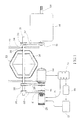
FIG 1 is a schematic diagram showing the various components of a driving device utilizing inertia according to an embodiment of the present invention. -
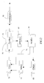
FIG 2 is a block diagram showing the interaction of the major functional components of the driving device utilizing inertia ofFIG 1 . - The following descriptions are exemplary embodiments only, and are not intended to limit the scope, applicability or configuration of the invention in any way. Rather, the following description provides a convenient illustration for implementing exemplary embodiments of the invention. Various changes to the described embodiments may be made in the function and arrangement of the elements described without departing from the scope of the invention as set forth in the appended claims.
- As shown in
FIGS. 1 and2 , a driving device utilizing inertia according to an embodiment of the present invention mainly contains abattery 10, amotor 20, aflywheel 30, acasing 40, atransmission box 50, agenerator 60, arectifier 70, and acharger 80. The driving device could be applied on various motor vehicles such as automobiles, vessels, planes, submarines, etc. where they are self-powered by the driving device. - The
battery 10 provides the required electricity to start themotor 20. Thebattery 10 is connected to and charged by thecharger 80 which draws its electricity from thegenerator 60 through therectifier 70. - The
motor 20 engages afirst shaft 31 of theflywheel 30 through afirst wheel 21 and abelt 22 so as to continuously spin theflywheel 30. - The
flywheel 30 is configured to have two conic shapes at two opposite ends, and is housed in avacuum chamber 33. Thefirst shaft 31 runs through theflywheel 30 and thevacuum chamber 33, andshaft seals 32 are used to secure the air-tightness of thevacuum chamber 33. Theflywheel 30 therefore could freely spin inside thevacuum chamber 33. Thefirst shaft 31 then runs across thecasing 40 throughbearings 34. Theshaft 31 is engaged to spin by themotor 20 through afourth wheel 35, and the torque produced is delivered to thetransmission box 50 through abelt 37 and asixth wheel 36, and to thegenerator 60 through anotherbelt 39 and afifth wheel 38. Thebearings 34 could be hydrostatic bearings, hydrodynamic bearings, magnetic levitation bearings, or non-contact bearings. - The
transmission box 50 receives torque from theflywheel 30 through athird wheel 51. Then, thetransmission box 50 delivers the torque after speed change to drive a vehicle such as automobile, vessel, plane, submarine, etc. through asecond shaft 52. - The
generator 60 receives torque from theflywheel 30 through asecond wheel 61 so as to continuously produce electricity Thegenerator 60, therectifier 70, thecharger 80, and thebattery 10 are series-connected in this order so that thebattery 10 is charged by thegenerator 60. - The
rectifier 70, as described, is series-connected between thegenerator 60 and thecharger 80 so as to store the electrical power from thegenerator 60 into thebattery 10. On the other hand, therectifier 70 is also connected to themotor 20 by apower cable 71 so as to provide electricity to themotor 20. - As described, the driving device could be installed on a vehicle so that the vehicle is self-powered without burning fossil fuel and without producing any CO2. The driving device therefore is extremely helpful for environmental protection.
- While certain novel features of this invention have been shown and described and are pointed out in the annexed claim, it is not intended to be limited to the details above, since it will be understood that various omissions, modifications, substitutions and changes in the forms and details of the device illustrated and in its operation can be made by those skilled in the art without departing in any way from the spirit of the present invention.
Claims (2)
- A driving device utilizing inertia for a vehicle, comprising a battery (10), a motor (20), a flywheel (30), a transmission box (50), a casing (40), a generator (60), and a rectifier (70), and a charger (80) wherein said battery (10) stores electricity required by starting said motor (20), said battery (10) is electrically connected to and charged by said charger (80);
said charger (80) is electrically connected to said rectifier (70); said rectifier (70) is electrically connected to said generator (60), said
motor (20), and said charger (80) so that electricity from said generator (60) is rectified and delivered to said motor (20) and is stored in said battery (10) via said charger (80);
said motor (20) spins a first shaft of said flywheel (30) via a first belt
connection;
said flywheel (30) is housed and freely spins in a vacuum chamber
by said first shaft while said first shaft engages and delivers torque to said generator (60) via a second belt connection, and to said transmission box (50) via a third belt connection, said first shaft is threaded through said casing (40) by two bearings; and
said transmission box (50) receives torque from said flywheel (30)
and delivers said torque after speed change to said vehicle through a second shaft of said transmission box (50). - The driving device according to claim 1, wherein each of said bearings is one of a hydrostatic bearing, a hydrodynamic bearing, a magnetic levitation bearing, and a non-contact bearing.
Priority Applications (1)
| Application Number | Priority Date | Filing Date | Title |
|---|---|---|---|
| EP10191135A EP2452847A1 (en) | 2010-11-15 | 2010-11-15 | Driving device utilizing inertia |
Applications Claiming Priority (1)
| Application Number | Priority Date | Filing Date | Title |
|---|---|---|---|
| EP10191135A EP2452847A1 (en) | 2010-11-15 | 2010-11-15 | Driving device utilizing inertia |
Publications (1)
| Publication Number | Publication Date |
|---|---|
| EP2452847A1 true EP2452847A1 (en) | 2012-05-16 |
Family
ID=43768953
Family Applications (1)
| Application Number | Title | Priority Date | Filing Date |
|---|---|---|---|
| EP10191135A Withdrawn EP2452847A1 (en) | 2010-11-15 | 2010-11-15 | Driving device utilizing inertia |
Country Status (1)
| Country | Link |
|---|---|
| EP (1) | EP2452847A1 (en) |
Cited By (2)
| Publication number | Priority date | Publication date | Assignee | Title |
|---|---|---|---|---|
| EP2947758A3 (en) * | 2014-05-21 | 2016-03-23 | Lin, Shih-Kuang | Magnetic levitation power device |
| SE2200094A1 (en) * | 2022-08-29 | 2024-03-01 | Yekshaveh Himan Chorkeh | Fuel-less electric generator device |
Citations (3)
| Publication number | Priority date | Publication date | Assignee | Title |
|---|---|---|---|---|
| US4233858A (en) * | 1976-12-27 | 1980-11-18 | The Garrett Corporation | Flywheel drive system having a split electromechanical transmission |
| GB2202302A (en) * | 1985-03-01 | 1988-09-21 | Laing John Services | Flywheels |
| US20040262062A1 (en) * | 2003-06-26 | 2004-12-30 | Berbari George Edmond | Flywheel-driven vehicle |
-
2010
- 2010-11-15 EP EP10191135A patent/EP2452847A1/en not_active Withdrawn
Patent Citations (3)
| Publication number | Priority date | Publication date | Assignee | Title |
|---|---|---|---|---|
| US4233858A (en) * | 1976-12-27 | 1980-11-18 | The Garrett Corporation | Flywheel drive system having a split electromechanical transmission |
| GB2202302A (en) * | 1985-03-01 | 1988-09-21 | Laing John Services | Flywheels |
| US20040262062A1 (en) * | 2003-06-26 | 2004-12-30 | Berbari George Edmond | Flywheel-driven vehicle |
Cited By (2)
| Publication number | Priority date | Publication date | Assignee | Title |
|---|---|---|---|---|
| EP2947758A3 (en) * | 2014-05-21 | 2016-03-23 | Lin, Shih-Kuang | Magnetic levitation power device |
| SE2200094A1 (en) * | 2022-08-29 | 2024-03-01 | Yekshaveh Himan Chorkeh | Fuel-less electric generator device |
Similar Documents
| Publication | Publication Date | Title |
|---|---|---|
| US8104560B1 (en) | Driving device utilizing inertia | |
| US9764631B2 (en) | Power transmission system of hybrid electric vehicle | |
| KR101427960B1 (en) | Power transmission system of hybrid electric vehicle | |
| KR101427959B1 (en) | Power transmission system of hybrid electric vehicle | |
| US9199529B2 (en) | Power transmission system of hybrid electric vehicle | |
| US20090294188A1 (en) | Motorized axle for use with environmentally friendly vehicles | |
| EP2803519B1 (en) | Electrical power generating engine flywheel with active torque control | |
| CN103158527A (en) | Power delivery device for vehicle | |
| Bassett et al. | The development of a range extender electric vehicle demonstrator | |
| EP2452847A1 (en) | Driving device utilizing inertia | |
| US20130093189A1 (en) | Method for generating additional electric energy in electric boats | |
| AU2010101258A4 (en) | Driving device utilizing inertia | |
| CA2720576A1 (en) | Driving device utilizing inertia | |
| US9278613B2 (en) | Power transmission system of hybrid electric vehicle | |
| KR101500381B1 (en) | Power transmission system of hybrid electric vehicle | |
| US20110271794A1 (en) | Hybrid electric vehicle generation system | |
| CN203957835U (en) | The electric complementary driving engine of a kind of electromagnetic clutch type oil | |
| CN202669525U (en) | Starting and power generation integrated machine for extended-range electric vehicle | |
| CN202623964U (en) | Vehicle assembled with moment conversion electronic box device | |
| US20130334873A1 (en) | System and method to re-use or recycle clean electricity from an electrical motor | |
| KR101490913B1 (en) | Power transmission system of hybrid electric vehicle | |
| KR101107863B1 (en) | Power generating apparatus and method for assisting engine | |
| TW201716261A (en) | Generator module and series hybrid electric power system use thereof | |
| CN209776182U (en) | Hybrid power system of new energy automobile | |
| CN203957832U (en) | The electric complementary driving engine of a kind of oil |
Legal Events
| Date | Code | Title | Description |
|---|---|---|---|
| PUAI | Public reference made under article 153(3) epc to a published international application that has entered the european phase |
Free format text: ORIGINAL CODE: 0009012 |
|
| 17P | Request for examination filed |
Effective date: 20101115 |
|
| AK | Designated contracting states |
Kind code of ref document: A1 Designated state(s): AL AT BE BG CH CY CZ DE DK EE ES FI FR GB GR HR HU IE IS IT LI LT LU LV MC MK MT NL NO PL PT RO RS SE SI SK SM TR |
|
| AX | Request for extension of the european patent |
Extension state: BA ME |
|
| STAA | Information on the status of an ep patent application or granted ep patent |
Free format text: STATUS: THE APPLICATION IS DEEMED TO BE WITHDRAWN |
|
| 18D | Application deemed to be withdrawn |
Effective date: 20130601 |