EP2452175B1 - Messgerät zur abgasmessung - Google Patents
Messgerät zur abgasmessung Download PDFInfo
- Publication number
- EP2452175B1 EP2452175B1 EP10724524.3A EP10724524A EP2452175B1 EP 2452175 B1 EP2452175 B1 EP 2452175B1 EP 10724524 A EP10724524 A EP 10724524A EP 2452175 B1 EP2452175 B1 EP 2452175B1
- Authority
- EP
- European Patent Office
- Prior art keywords
- measuring
- exhaust gas
- gas
- measuring device
- pump
- Prior art date
- Legal status (The legal status is an assumption and is not a legal conclusion. Google has not performed a legal analysis and makes no representation as to the accuracy of the status listed.)
- Active
Links
Images

Classifications
-
- G—PHYSICS
- G01—MEASURING; TESTING
- G01M—TESTING STATIC OR DYNAMIC BALANCE OF MACHINES OR STRUCTURES; TESTING OF STRUCTURES OR APPARATUS, NOT OTHERWISE PROVIDED FOR
- G01M15/00—Testing of engines
- G01M15/04—Testing internal-combustion engines
- G01M15/10—Testing internal-combustion engines by monitoring exhaust gases or combustion flame
- G01M15/102—Testing internal-combustion engines by monitoring exhaust gases or combustion flame by monitoring exhaust gases
- G01M15/108—Testing internal-combustion engines by monitoring exhaust gases or combustion flame by monitoring exhaust gases using optical methods
Definitions
- the invention relates to a measuring device for measuring the exhaust gas of motor vehicles, which inter alia, a combined measurement of Rauchgastrübung, the particle concentration, and the CO, CO 2 , HC, O 2 , NO, NO 2 , NO x - and NH 3 - exhaust gas and thus a shortening of the measuring period allows.
- Measuring devices for measuring the exhaust gas of motor vehicles are used for testing and diagnosis of vehicle exhaust gases. Due to the increasingly stringent exhaust gas regulations according to, for example, Euro 4 or 5, different exhaust gas measuring devices for motor vehicles are known from the prior art. For example, so-called 4- or 5-gas exhaust gas measuring devices for petrol and gas-powered gasoline engines measure the gases CO, CO 2 , HC, O 2 or NO by means of an IR measuring bench. Diesel emission testers (opacimeters) measure the smoke gas turbidity with a light turbidity measurement method. Other emission measuring devices, so-called particle measuring devices, measure the proportion of particulate matter in diesel and gasoline exhaust gas. Furthermore, devices are known which measure the NO, NO 2 or NO x content in the exhaust gas, or devices which measure the NH 3 content.
- US Pat. No. 5,918,256 describes a vehicle emission analysis interface system for providing a sample of an exhaust of a test vehicle at the inlet of an analyzer to provide a quantitative measurement of selected pollutants.
- the DE 19 653 333 A1 concerns an exhaust gas tester for internal combustion engines in which the sample gas is pumped by a measuring cell with a pump, the water vapor is separated in the sample gas by a condensate and pumped with another pump, a measuring device determines the water level in the condenser.
- the measuring device for determining a plurality of exhaust gas components in the exhaust gas of internal combustion engines comprises an exhaust gas probe, a particle measuring chamber, a fine filter, a water separator, an infrared measuring bench, an O 2 sensor and a gas outlet.
- the exhaust gas measuring device is characterized in particular by the arrangement according to the invention of the aforementioned components, which is such that a measuring gas enters via the exhaust gas probe, then passed into the particle measuring chamber, then passed into the fine filter, then passed into the water separator, then directed into the infrared measuring bench, then directed to the O2 sensor, and finally exiting through the gas outlet back into the environment.
- a K value for the opacity of the measurement gas can be determined by means of a linear conversion method from a measurement gas particle concentration value determined by the particle measurement chamber.
- the opacity can also be determined at the same time by means of the particle measuring chamber, thereby avoiding a separate opacimeter, which enables a more compact and cost-effective design.
- the inventors have found in experimental series that the measured values of the particle measuring chamber according to the invention are linearly correlated with the K value for the opacity of the measuring gas. Therefore, the measured values taken by the particle measuring chamber by means of the laser scattered light method can also be used to determine the opacity. As a result, an additional time-consuming opacity measurement can be avoided.
- the diesel exhaust gas analysis is determined by means of a turbidity measurement, whereby the exhaust gas jet is illuminated and measured with a green LED in a measuring chamber of the length of approx. 43 cm.
- the combination and arrangement of the measuring device components according to the invention makes possible a multifunctional exhaust gas measuring device for all common types of exhaust gas.
- the measurement of a plurality of exhaust gas components takes place on the basis of a defined exhaust gas volume unit.
- a specific exhaust gas volume unit which is passed through the inventive arrangement of the measuring components, the various exhaust gas components and measurements performed. It is particularly advantageous that the measurement thus takes place quasi-simultaneously, since the defined volume unit is passed, for example, within a few fractions of a second of the measurement in the particle measuring chamber for measurement in the IR measuring chamber.
- the measurement of all measured values can also take place simultaneously.
- the construction according to the invention makes it possible to use the same measuring device components for different types of exhaust gas, for example only one exhaust gas probe, one water cutter, one power supply, one housing, and one display display is required, thus enabling a more compact and cheaper construction. It is also particularly advantageous that the user no longer has different measuring devices for different Flue gas measurement must operate, but only one device, which increases the operating safety.
- the particle measuring chamber preferably measures the measurement gas particle concentration (mass concentration) by means of a laser scattered light method.
- the use of a laser scattered light method for an exhaust gas measurement allows a much more compact design of the particle measuring chamber, wherein, for example, the particle measuring cell can be cylindrical with a height of 8 cm and a transverse diameter of 4 cm.
- the meter further comprises a pump motor, a sample gas pump and a water separator pump, the pump motor driving the sample gas pump and the water separator pump.
- the pump and the motor can be used for different types of measurement, whereas in separate measuring devices known from the relevant art each have a separate sample gas pump, a Wasserabscheiderpumpe and a pump motor for 4- / 5-gas measurement, the opacity measurement, and the Particle measurement is needed.
- the sample gas pump is preferably arranged in a sample gas line between the water separator and the infrared measurement bench.
- the sample gas pump and the Wasserabscheiderpumpe are designed as double diaphragm pumps.
- the measuring gas is passed after the IR measuring bench to an NO sensor, a NO 2 sensor, and / or an NH 3 sensor, which are connected in parallel to the O 2 sensor.
- the measuring gas preferably passes through a heating element before it enters the particle measuring chamber.
- the inventors have observed in the development of the particle measuring chamber according to the invention by means of a laser scattered light method, the effect that can result from condensation droplets in the exhaust stream optical interference effects in the laser-based particle measurement. These parasitic effects can be reliably avoided by heating the exhaust gas flow by switching on a heating element in front of it.
- a measuring device for quasi-simultaneous measurement of different exhaust gas components of internal combustion engines such as the Rauchgastrübung, the particle concentration, as well as the CO, CO 2 , HC, O 2 , NO, NO 2 , NO x - and NH 3 - Exhaust gas content, allows.
- the inventive combination and arrangement of the meter components and the tubing is crucial.
- the arrangement of the water separator downstream of the particle measuring chamber and upstream of the IR measuring bench reliably ensures that on the one hand the measuring gas is cleaned of disturbing moisture and particles for the IR measurement, on the other hand avoids that the particle concentration is changed by the water separator before this was measured in the particle measuring chamber.
- the arrangement and tubing according to the invention for the measurement of Rauchgastrübung, the particle concentration, and the CO, CO 2 , HC, O 2 , NO, NO 2 , NO x - and NH 3 - exhaust gas only a total of a pump motor , a sample gas pump and a water separator pump is needed.
- the combination device according to the invention allows a significantly shortened exhaust gas measurement time and facilitates the handling of the device in mobile use as well as in the workshop use. Furthermore, identical or similar components of the measuring device can be saved since only one exhaust gas probe, a water separator, a power supply, a housing and a display display are necessary for the measuring device according to the invention.
- the use according to the invention of a laser scattering light method for the determination of the mass concentration and the calculation of the opacity from the mass concentration furthermore enables a very compact design by the laser-based measuring cell and by saving a separate opacity measuring unit.
- Fig. 1 schematically shows a structure of a measuring device according to an embodiment of the present invention.
- the meter includes an exhaust probe 10 which is brought into the exhaust pipe of the vehicle to be examined.
- the exhaust gas samples taken by the vehicle are conducted via an exhaust gas probe line 101 to a zero point calibration valve 13.
- This valve is a 3/2 normally open valve to suck exhaust samples.
- the meter has an ambient air inlet 11.
- the air samples taken from the ambient air are via an ambient air line 102 via a fine filter 12 to the zero point calibration valve 13.
- By selectively switching the zero point calibration valve 13 can be changed between the intake of exhaust gas or ambient air.
- "clean" air from the ambient air inlet 11 is used.
- a heating element 14 is arranged via a line 104.
- the exhaust gases cool on the approximately 1.5 m long line from the exhaust gas probe 10 to the heating element 114.
- the heating element 14 heats the exhaust gas samples and thereby reduces the number and size of the water droplets in the measurement gas.
- the measuring gas is passed from the heating element 14 into the particle measuring chamber 15.
- the mass concentration in mg / m 3 of the soot particles contained in the exhaust gas is determined by means of a laser scattering light method.
- a red laser beam is directed into the exhaust gas jet, where it is scattered by the exhaust soot particles.
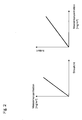
- This scattering of the laser light on the exhaust soot particles is detected via an optical receiver (not shown) located in the particle measuring chamber 15, amplified via a connected amplifier (not shown) and subsequently evaluated in a connected data processing unit (not shown). From the strength of the detected scattered laser light, the mass concentration in mg / m 3 of the soot particles contained in the exhaust gas is determined. This is in the left diagram in Fig. 2 illustrating, by way of example and schematically, the dependence of the mass concentration of the laser scattered light of the particle measuring chamber.
- a K value in 1 / m is calculated for the opacity of the measurement gas by means of a linear conversion method.
- the inventors have determined in test series that the measured values of the mass concentration of the laser-based scattered light method are linearly correlated with the K value for the opacity of the measurement gas. This is in the right diagram in Fig. 2 illustrating, by way of example and schematically, the linear relationship between the K value of the opacity and the measured mass concentration. Therefore, the measured values taken by the particle measuring chamber 15 by means of the laser scattered light method can also be used to determine the opacity. As a result, no separate opacity measuring device is necessary.
- the laser scattering method according to the present invention can therefore determine the soot particle concentration and the opacity of the exhaust gases by means of an extremely compact measuring cell having a height of 8 cm and a circular transverse diameter of 4 cm.
- a fine filter 16 Downstream of the particle measuring chamber 15, a fine filter 16 is arranged via a fine filter line 106; downstream of this fine filter 16, a water separator 17 is arranged via a water separator line 107.
- the measurement gas for the IR measurement of interfering impurities and moisture is cleaned.
- the water separated in the water separator 17 is discharged via a water outlet line 108 via the water outlet 33 by means of a water separator pump 24.
- a sample gas test valve 20 Downstream of the water separator 17, a sample gas test valve 20, which is in connection with a line 117 which is connected to a zero gas valve 19, is arranged via a sample gas test line 109 for receiving the sample gas from the water separator 17.
- the sample gas test valve 20 and the zero gas valve 19 are designed as 3/2 normally open valves.
- the sample gas test valve 20 a mixture of ambient air and calibration gas is supplied.
- the ambient air is drawn in via an ambient air inlet 34 and cleaned by an activated carbon filter 18 before entering the zero gas valve 19.
- the calibration gas is supplied to the zero gas valve 19 via a calibration gas probe 35.
- the calibration gas is used to calibrate the IR bench 27.
- a sample gas pump 23 Downstream of the test gas test unit 20, a sample gas pump 23 is arranged, which is designed as a double diaphragm pump. By means of the sample gas pump 23 the measuring gases are conveyed via an IR-measuring line 111 to the IR measuring bank 27.
- the IR measuring bench can determine the CO, CO 2 and HC contents contained in the sample gas and additionally the A value (measure of the O 2 partial pressure).
- an O 2 sensor 28, an NO sensor 29, a NO 2 can be downstream of the IR measurement bench via a sensor line 114 Sensor 30 and an NH 3 sensor 31 may be arranged in parallel.
- the measuring gas exits via a gas outlet 32 from the meter.
- sample gas lines 114 and 115 and the terminals for the sensors 29, 30 and 31 may also be arranged as in the previously described embodiment, but without providing the sensors 29, 30 and 31. These can optionally be retrofitted at a later date.
- a pressure sensor element 21 is arranged between the sample gas pump 23 and the water separator 17.
- a further pressure sensor element 26 is arranged between the sample gas pump 23 and IR measuring bench 27.
- These pressure sensor elements measure the air pressure, and can also record current and voltage values, for example, the measuring bench 27. From the measured air pressure values of the pressure sensor elements 21 and 26, it can be detected, for example, whether one of the input probes of the measuring device is in the water. In this case, the meter can be turned off to prevent damage to the instrumentation due to water ingress.
- the sample gas pump 23 is driven by a pump motor 22.
- This pump motor 22 is disposed between the sample gas pump 23 and the water separator pump 24 and further drives the Wasserabscheiderpumpe 24 at.
- the inventive tubing, ie wiring in the meter the measuring device according to the invention requires, in contrast to the known from the relevant art measuring equipment for measuring the Rauchgastrübung, the particle concentration, and the CO, CO 2 , HC, O 2 , NO, NO 2 , NO x - and NH 3 - exhaust gas only a total of a pump motor 22, a sample gas pump 23 and a Wasserabscheiderpumpe 24th
- the combination and arrangement of the meter components according to the invention makes possible a multifunctional exhaust gas measuring device for all conventional exhaust gas measuring methods, which comprises a quasi-simultaneous measurement of the flue gas turbidity, the particle concentration, and the CO, CO 2 , HC, O 2 , NO, NO 2 , NO x - and NH 3 - allows exhaust gas content.
- the measurements can also be carried out continuously or intermittently, wherein a temporal difference of seconds fractions between the individual measurements can be.
- a specific volume unit of the measuring gas is passed from the exhaust gas probe 10 through the various measuring cell and sensors.
- the abovementioned measurements are carried out on the basis of the same volume unit of the measurement gas, in contrast to measuring devices known from the relevant prior art, where measurement is carried out successively by means of a plurality of different measuring devices, each with its own exhaust gas probe based on different measurement gas volume units.
Priority Applications (1)
| Application Number | Priority Date | Filing Date | Title |
|---|---|---|---|
| EP15200066.7A EP3026415A1 (de) | 2009-07-09 | 2010-06-18 | Messgerät zur abgasmessung |
Applications Claiming Priority (2)
| Application Number | Priority Date | Filing Date | Title |
|---|---|---|---|
| DE200910027599 DE102009027599A1 (de) | 2009-07-09 | 2009-07-09 | Messgerät zur Abgasmessung |
| PCT/EP2010/058664 WO2011003720A1 (de) | 2009-07-09 | 2010-06-18 | Messgerät zur abgasmessung |
Related Child Applications (1)
| Application Number | Title | Priority Date | Filing Date |
|---|---|---|---|
| EP15200066.7A Division EP3026415A1 (de) | 2009-07-09 | 2010-06-18 | Messgerät zur abgasmessung |
Publications (2)
| Publication Number | Publication Date |
|---|---|
| EP2452175A1 EP2452175A1 (de) | 2012-05-16 |
| EP2452175B1 true EP2452175B1 (de) | 2015-12-16 |
Family
ID=42667983
Family Applications (2)
| Application Number | Title | Priority Date | Filing Date |
|---|---|---|---|
| EP10724524.3A Active EP2452175B1 (de) | 2009-07-09 | 2010-06-18 | Messgerät zur abgasmessung |
| EP15200066.7A Withdrawn EP3026415A1 (de) | 2009-07-09 | 2010-06-18 | Messgerät zur abgasmessung |
Family Applications After (1)
| Application Number | Title | Priority Date | Filing Date |
|---|---|---|---|
| EP15200066.7A Withdrawn EP3026415A1 (de) | 2009-07-09 | 2010-06-18 | Messgerät zur abgasmessung |
Country Status (4)
| Country | Link |
|---|---|
| EP (2) | EP2452175B1 (un) |
| DE (1) | DE102009027599A1 (un) |
| ES (1) | ES2562179T3 (un) |
| WO (1) | WO2011003720A1 (un) |
Families Citing this family (3)
| Publication number | Priority date | Publication date | Assignee | Title |
|---|---|---|---|---|
| DE202013103647U1 (de) | 2013-08-12 | 2013-09-02 | Aspect Imaging Ltd. | Ein System zum Online-Messen und Steuern von O2-Fraktion, CO-Fraktion und CO2-Fraktion |
| CN112986070B (zh) * | 2021-05-12 | 2021-08-17 | 西安多普多信息科技有限公司 | 一种尾气检测装置、方法和系统 |
| CN114167002A (zh) * | 2021-12-08 | 2022-03-11 | 西安多普多信息科技有限公司 | 污染物快速检测方法和装置 |
Citations (3)
| Publication number | Priority date | Publication date | Assignee | Title |
|---|---|---|---|---|
| DE19653333A1 (de) | 1996-12-20 | 1998-07-02 | Hermann Electronic Gmbh | Abgastester |
| US5918256A (en) | 1997-10-27 | 1999-06-29 | Delaney; William O. | Motor vehicle emission analysis system |
| DE10057652A1 (de) | 1999-11-26 | 2001-06-07 | Avl List Gmbh | Verfahren zur Messung der Opazität in Gasen |
Family Cites Families (2)
| Publication number | Priority date | Publication date | Assignee | Title |
|---|---|---|---|---|
| US5993743A (en) * | 1997-03-26 | 1999-11-30 | Spx Corporation | Hand-held vehicle exhaust analyzer |
| US20040052683A1 (en) * | 2002-06-05 | 2004-03-18 | Snap-On Technologies, Inc. | Portable vehicle exhaust analyzer module |
-
2009
- 2009-07-09 DE DE200910027599 patent/DE102009027599A1/de not_active Withdrawn
-
2010
- 2010-06-18 WO PCT/EP2010/058664 patent/WO2011003720A1/de active Application Filing
- 2010-06-18 EP EP10724524.3A patent/EP2452175B1/de active Active
- 2010-06-18 EP EP15200066.7A patent/EP3026415A1/de not_active Withdrawn
- 2010-06-18 ES ES10724524.3T patent/ES2562179T3/es active Active
Patent Citations (3)
| Publication number | Priority date | Publication date | Assignee | Title |
|---|---|---|---|---|
| DE19653333A1 (de) | 1996-12-20 | 1998-07-02 | Hermann Electronic Gmbh | Abgastester |
| US5918256A (en) | 1997-10-27 | 1999-06-29 | Delaney; William O. | Motor vehicle emission analysis system |
| DE10057652A1 (de) | 1999-11-26 | 2001-06-07 | Avl List Gmbh | Verfahren zur Messung der Opazität in Gasen |
Non-Patent Citations (12)
| Title |
|---|
| "Instandsetzungsanweisung: Rauchgas-Trübungs-Modul", RTM 430 IN VERBINDUNG MIT KD-SOFTWARE 1 687 000 661 UND VERBINDUNGSLEITUNG 1 684 463 389;, 28 September 2004 (2004-09-28) |
| "Instruments for measuring vehicle exhaust emis- sionsPart 1: Metrological and technical requirements; Part2: Metrological controls and per- formance tests);", OIML R 99-1 & 2 EDITION 2008 (E), 2008, pages 1 - 46, XP055323826, Retrieved from the Internet <URL:https://www.oiml.org/en/files/pdf_r/r099-1-2-e08.pdf> |
| "OIML R 99-1 & 2 Edition 2008 (E); Instruments for measuring vehicle exhaust emis- sions", PART1: METROLOGICAL AND TECHNICAL REQUIREMENTS; PART2: METROLOGICAL CONTROLS AND PER- FORMANCE TESTS); |
| "Optimierung eines Messaufbaus für die Anforderungen eines Normals für ein Ruß- rosol hinsichtlich Trubungskoeffizienten und Massendichte im oberen Konzentrationsbereich'';", FAKULTÄT VERSORGUNGSTECHNIK DER OSTFALIA HOCHSCHULE FÜR ANGEWANDTE WISSENSCHAFTEN;, 16 January 2015 (2015-01-16) |
| ANONYMOUS: "Anforderungen für die Messung von Russpartikeln", EAST SOLUTIONS, 6 March 2009 (2009-03-06), pages 1 - 4, XP002600226, Retrieved from the Internet <URL:http://www.eastsolutions.eu/html/messigkeiten.html> |
| ANONYMOUS: "Anforderungen für die Messung von Russpartikeln'';", 6 March 2009 (2009-03-06), XP002600226, Retrieved from the Internet <URL:http://www.eastsolutions.eu/html/messigkeiten.html> |
| BOSCH: "Instandsetzungsanweisung", BOSCH-EMISSIONS-ANALYSE BEA- MODUL (BEA050), 21 July 2008 (2008-07-21), pages 1 - 65, XP055318095 |
| BOSCH: "Rauchgas-Trübungs-Modul, RTM 430 in Verbindung mit KD-Software 1 687 000 661 und Verbindungsleitung 1 684 463 389", INSTANDSETZUNGSANWEISUNG, 28 September 2004 (2004-09-28), pages 1 - 86, XP055323828 |
| HOMAN, H.S: "Conversion Factors among Smoke Measurements", SAE TECHNICAL PAPER 850267, 1985, pages FP - 15, XP055323833 |
| HOMAN, H.S: "Conversion Factors among Smoke Measurements'';", SAE TECHNICAL PAPER 850267, 1985 |
| INSTANDSETZUNGSANWEISUNG: BOSCH-EMISSIONS-ANALYSE BEA- MODUL (BEA050);, 21 July 2008 (2008-07-21) |
| KATHARINA OLZEM: "Optimierung eines Messaufbaus für die Anforderungen eines Normals für ein Rußae- rosol hinsichtlich Trübungskoeffizienten und Massendichte im oberen Konzentrationsbereich", ERLAGUNG DES AKADEMISCHEN GRADES MASTER OF ENGINEERING, 16 January 2015 (2015-01-16), Ostfalia Hochschule für angewandte Wissenschaften, XP055323830 |
Also Published As
| Publication number | Publication date |
|---|---|
| WO2011003720A1 (de) | 2011-01-13 |
| DE102009027599A1 (de) | 2011-01-13 |
| EP3026415A1 (de) | 2016-06-01 |
| ES2562179T3 (es) | 2016-03-02 |
| EP2452175A1 (de) | 2012-05-16 |
Similar Documents
| Publication | Publication Date | Title |
|---|---|---|
| DE102007014761B4 (de) | Verfahren zum Betreiben eines sammelnden Partikelsensors und Vorrichtung zur Durchführung des Verfahrens | |
| DE2509411C2 (de) | Vorrichtung zum Analysieren des Emissions-Gehalts der Abgase eines Verbrennungsmotors | |
| EP0668495B1 (de) | Messanlage für Brennkraftmaschinen-Abgaspartikel (Russ) | |
| DE102007042086B4 (de) | Testverfahren für eine Abgassonde einer Brennkraftmaschine, insbesondere für eine Lambda-Sonde | |
| DE112006001069T5 (de) | Partikelaufnahmesystem mit Flussüberprüfungsvorrichtung | |
| DE202011110972U1 (de) | Abgasanalysesystem | |
| EP2414808B1 (de) | Anlage zur entnahme von abgasproben von verbrennungskraftmaschinen | |
| DE112009002558T5 (de) | Partikelprobenentnahmesystem und Verfahren zum Verringern einer Überentnahme während Übergängen | |
| WO2003091553A1 (de) | Vorrichtung und verfahren zur feststellung einer fehlfunktion eines filters | |
| WO1999010728A2 (de) | Vorrichtung zur analyse des abgases von kraftfahrzeugen | |
| EP2452175B1 (de) | Messgerät zur abgasmessung | |
| DE102015224935B4 (de) | Verfahren, Vorrichtung und System zum Betreiben eines Stickoxidsensors | |
| DE102008060248A1 (de) | Tankentlüftungssystem | |
| AT521017A4 (de) | Verfahren zur Kalibrierung eines Massenstrommessers in einer Constant Volume Sampling (CVS) Abgasanalyseanlage | |
| DE102015202870A1 (de) | Verfahren zur Bestimmung des Taupunktendes im Abgastrakt einer Verbrennungsmaschine | |
| EP2756281A1 (de) | VERFAHREN UND VORRICHTUNG ZUR ERMITTLUNG DER KONZENTRATION VON AEROSOLEN IN HEIßEN GASEN, INSBESONDERE IN ABGASEN VON VERBRENNUNGSKRAFTMASCHINEN | |
| DE10205966A1 (de) | Verfahren und Vorrichtung zur Überwachung der Funktionsfähigkeit eines Sekundärluftsystems | |
| EP3222833A1 (de) | Verfahren zur überprüfung der nox-emissionen eines fahrzeugs | |
| DE102010038331A1 (de) | Messgerät zur Abgasmessung | |
| DE4420193C2 (de) | Anordnung zur Erfassung von Schadstoffen bei Kraftfahrzeugmotoren mit Selbstzündung | |
| DE102005013914A1 (de) | Vorrichtung zur Druckmessung | |
| EP1923694B1 (de) | Verfahren und Vorrichtung zum Bestimmen einer Ölmenge in einer Gasströmung | |
| EP2500707B1 (de) | Messgerät zur Abgasmessung | |
| DE19831457A1 (de) | Nachrüstvorrichtung zum Erfassen der Abgaszusammensetzung im Kraftfahrzeug zum Selbsteinbau | |
| DE102018214221B4 (de) | Verfahren zum Überprüfen einer zum Bestimmen von zumindest einer Fluideigenschaft ausgebildeten Vorrichtung |
Legal Events
| Date | Code | Title | Description |
|---|---|---|---|
| PUAI | Public reference made under article 153(3) epc to a published international application that has entered the european phase |
Free format text: ORIGINAL CODE: 0009012 |
|
| 17P | Request for examination filed |
Effective date: 20120209 |
|
| AK | Designated contracting states |
Kind code of ref document: A1 Designated state(s): AL AT BE BG CH CY CZ DE DK EE ES FI FR GB GR HR HU IE IS IT LI LT LU LV MC MK MT NL NO PL PT RO SE SI SK SM TR |
|
| DAX | Request for extension of the european patent (deleted) | ||
| 17Q | First examination report despatched |
Effective date: 20130430 |
|
| GRAP | Despatch of communication of intention to grant a patent |
Free format text: ORIGINAL CODE: EPIDOSNIGR1 |
|
| INTG | Intention to grant announced |
Effective date: 20150612 |
|
| GRAS | Grant fee paid |
Free format text: ORIGINAL CODE: EPIDOSNIGR3 |
|
| GRAA | (expected) grant |
Free format text: ORIGINAL CODE: 0009210 |
|
| STAA | Information on the status of an ep patent application or granted ep patent |
Free format text: STATUS: THE PATENT HAS BEEN GRANTED |
|
| AK | Designated contracting states |
Kind code of ref document: B1 Designated state(s): AL AT BE BG CH CY CZ DE DK EE ES FI FR GB GR HR HU IE IS IT LI LT LU LV MC MK MT NL NO PL PT RO SE SI SK SM TR |
|
| REG | Reference to a national code |
Ref country code: GB Ref legal event code: FG4D Free format text: NOT ENGLISH |
|
| REG | Reference to a national code |
Ref country code: CH Ref legal event code: EP |
|
| REG | Reference to a national code |
Ref country code: IE Ref legal event code: FG4D Free format text: LANGUAGE OF EP DOCUMENT: GERMAN |
|
| REG | Reference to a national code |
Ref country code: AT Ref legal event code: REF Ref document number: 765791 Country of ref document: AT Kind code of ref document: T Effective date: 20160115 |
|
| REG | Reference to a national code |
Ref country code: DE Ref legal event code: R096 Ref document number: 502010010785 Country of ref document: DE |
|
| REG | Reference to a national code |
Ref country code: SE Ref legal event code: TRGR |
|
| REG | Reference to a national code |
Ref country code: ES Ref legal event code: FG2A Ref document number: 2562179 Country of ref document: ES Kind code of ref document: T3 Effective date: 20160302 |
|
| REG | Reference to a national code |
Ref country code: NL Ref legal event code: MP Effective date: 20151216 |
|
| REG | Reference to a national code |
Ref country code: LT Ref legal event code: MG4D |
|
| PG25 | Lapsed in a contracting state [announced via postgrant information from national office to epo] |
Ref country code: HR Free format text: LAPSE BECAUSE OF FAILURE TO SUBMIT A TRANSLATION OF THE DESCRIPTION OR TO PAY THE FEE WITHIN THE PRESCRIBED TIME-LIMIT Effective date: 20151216 Ref country code: NO Free format text: LAPSE BECAUSE OF FAILURE TO SUBMIT A TRANSLATION OF THE DESCRIPTION OR TO PAY THE FEE WITHIN THE PRESCRIBED TIME-LIMIT Effective date: 20160316 Ref country code: LT Free format text: LAPSE BECAUSE OF FAILURE TO SUBMIT A TRANSLATION OF THE DESCRIPTION OR TO PAY THE FEE WITHIN THE PRESCRIBED TIME-LIMIT Effective date: 20151216 |
|
| PG25 | Lapsed in a contracting state [announced via postgrant information from national office to epo] |
Ref country code: GR Free format text: LAPSE BECAUSE OF FAILURE TO SUBMIT A TRANSLATION OF THE DESCRIPTION OR TO PAY THE FEE WITHIN THE PRESCRIBED TIME-LIMIT Effective date: 20160317 Ref country code: LV Free format text: LAPSE BECAUSE OF FAILURE TO SUBMIT A TRANSLATION OF THE DESCRIPTION OR TO PAY THE FEE WITHIN THE PRESCRIBED TIME-LIMIT Effective date: 20151216 Ref country code: NL Free format text: LAPSE BECAUSE OF FAILURE TO SUBMIT A TRANSLATION OF THE DESCRIPTION OR TO PAY THE FEE WITHIN THE PRESCRIBED TIME-LIMIT Effective date: 20151216 Ref country code: FI Free format text: LAPSE BECAUSE OF FAILURE TO SUBMIT A TRANSLATION OF THE DESCRIPTION OR TO PAY THE FEE WITHIN THE PRESCRIBED TIME-LIMIT Effective date: 20151216 |
|
| REG | Reference to a national code |
Ref country code: FR Ref legal event code: PLFP Year of fee payment: 7 |
|
| PG25 | Lapsed in a contracting state [announced via postgrant information from national office to epo] |
Ref country code: CZ Free format text: LAPSE BECAUSE OF FAILURE TO SUBMIT A TRANSLATION OF THE DESCRIPTION OR TO PAY THE FEE WITHIN THE PRESCRIBED TIME-LIMIT Effective date: 20151216 |
|
| PG25 | Lapsed in a contracting state [announced via postgrant information from national office to epo] |
Ref country code: PT Free format text: LAPSE BECAUSE OF FAILURE TO SUBMIT A TRANSLATION OF THE DESCRIPTION OR TO PAY THE FEE WITHIN THE PRESCRIBED TIME-LIMIT Effective date: 20160418 Ref country code: SK Free format text: LAPSE BECAUSE OF FAILURE TO SUBMIT A TRANSLATION OF THE DESCRIPTION OR TO PAY THE FEE WITHIN THE PRESCRIBED TIME-LIMIT Effective date: 20151216 Ref country code: IS Free format text: LAPSE BECAUSE OF FAILURE TO SUBMIT A TRANSLATION OF THE DESCRIPTION OR TO PAY THE FEE WITHIN THE PRESCRIBED TIME-LIMIT Effective date: 20160416 Ref country code: SM Free format text: LAPSE BECAUSE OF FAILURE TO SUBMIT A TRANSLATION OF THE DESCRIPTION OR TO PAY THE FEE WITHIN THE PRESCRIBED TIME-LIMIT Effective date: 20151216 Ref country code: RO Free format text: LAPSE BECAUSE OF FAILURE TO SUBMIT A TRANSLATION OF THE DESCRIPTION OR TO PAY THE FEE WITHIN THE PRESCRIBED TIME-LIMIT Effective date: 20151216 Ref country code: EE Free format text: LAPSE BECAUSE OF FAILURE TO SUBMIT A TRANSLATION OF THE DESCRIPTION OR TO PAY THE FEE WITHIN THE PRESCRIBED TIME-LIMIT Effective date: 20151216 |
|
| REG | Reference to a national code |
Ref country code: DE Ref legal event code: R026 Ref document number: 502010010785 Country of ref document: DE |
|
| PLBI | Opposition filed |
Free format text: ORIGINAL CODE: 0009260 |
|
| 26 | Opposition filed |
Opponent name: ROBERT BOSCH GMBH Effective date: 20160915 |
|
| PG25 | Lapsed in a contracting state [announced via postgrant information from national office to epo] |
Ref country code: DK Free format text: LAPSE BECAUSE OF FAILURE TO SUBMIT A TRANSLATION OF THE DESCRIPTION OR TO PAY THE FEE WITHIN THE PRESCRIBED TIME-LIMIT Effective date: 20151216 Ref country code: PL Free format text: LAPSE BECAUSE OF FAILURE TO SUBMIT A TRANSLATION OF THE DESCRIPTION OR TO PAY THE FEE WITHIN THE PRESCRIBED TIME-LIMIT Effective date: 20151216 |
|
| PLAX | Notice of opposition and request to file observation + time limit sent |
Free format text: ORIGINAL CODE: EPIDOSNOBS2 |
|
| PG25 | Lapsed in a contracting state [announced via postgrant information from national office to epo] |
Ref country code: BE Free format text: LAPSE BECAUSE OF NON-PAYMENT OF DUE FEES Effective date: 20160630 |
|
| PG25 | Lapsed in a contracting state [announced via postgrant information from national office to epo] |
Ref country code: MC Free format text: LAPSE BECAUSE OF FAILURE TO SUBMIT A TRANSLATION OF THE DESCRIPTION OR TO PAY THE FEE WITHIN THE PRESCRIBED TIME-LIMIT Effective date: 20151216 |
|
| REG | Reference to a national code |
Ref country code: CH Ref legal event code: PL |
|
| PG25 | Lapsed in a contracting state [announced via postgrant information from national office to epo] |
Ref country code: SI Free format text: LAPSE BECAUSE OF FAILURE TO SUBMIT A TRANSLATION OF THE DESCRIPTION OR TO PAY THE FEE WITHIN THE PRESCRIBED TIME-LIMIT Effective date: 20151216 |
|
| REG | Reference to a national code |
Ref country code: IE Ref legal event code: MM4A |
|
| PLBB | Reply of patent proprietor to notice(s) of opposition received |
Free format text: ORIGINAL CODE: EPIDOSNOBS3 |
|
| PG25 | Lapsed in a contracting state [announced via postgrant information from national office to epo] |
Ref country code: CH Free format text: LAPSE BECAUSE OF NON-PAYMENT OF DUE FEES Effective date: 20160630 Ref country code: LI Free format text: LAPSE BECAUSE OF NON-PAYMENT OF DUE FEES Effective date: 20160630 |
|
| PG25 | Lapsed in a contracting state [announced via postgrant information from national office to epo] |
Ref country code: IE Free format text: LAPSE BECAUSE OF NON-PAYMENT OF DUE FEES Effective date: 20160618 |
|
| REG | Reference to a national code |
Ref country code: FR Ref legal event code: PLFP Year of fee payment: 8 |
|
| REG | Reference to a national code |
Ref country code: AT Ref legal event code: MM01 Ref document number: 765791 Country of ref document: AT Kind code of ref document: T Effective date: 20160618 |
|
| PG25 | Lapsed in a contracting state [announced via postgrant information from national office to epo] |
Ref country code: AT Free format text: LAPSE BECAUSE OF NON-PAYMENT OF DUE FEES Effective date: 20160618 |
|
| PG25 | Lapsed in a contracting state [announced via postgrant information from national office to epo] |
Ref country code: HU Free format text: LAPSE BECAUSE OF FAILURE TO SUBMIT A TRANSLATION OF THE DESCRIPTION OR TO PAY THE FEE WITHIN THE PRESCRIBED TIME-LIMIT; INVALID AB INITIO Effective date: 20100618 Ref country code: CY Free format text: LAPSE BECAUSE OF FAILURE TO SUBMIT A TRANSLATION OF THE DESCRIPTION OR TO PAY THE FEE WITHIN THE PRESCRIBED TIME-LIMIT Effective date: 20151216 |
|
| PLCK | Communication despatched that opposition was rejected |
Free format text: ORIGINAL CODE: EPIDOSNREJ1 |
|
| STAA | Information on the status of an ep patent application or granted ep patent |
Free format text: STATUS: THE PATENT HAS BEEN GRANTED |
|
| REG | Reference to a national code |
Ref country code: FR Ref legal event code: PLFP Year of fee payment: 9 |
|
| PG25 | Lapsed in a contracting state [announced via postgrant information from national office to epo] |
Ref country code: LU Free format text: LAPSE BECAUSE OF NON-PAYMENT OF DUE FEES Effective date: 20160618 Ref country code: MT Free format text: LAPSE BECAUSE OF FAILURE TO SUBMIT A TRANSLATION OF THE DESCRIPTION OR TO PAY THE FEE WITHIN THE PRESCRIBED TIME-LIMIT Effective date: 20151216 Ref country code: MK Free format text: LAPSE BECAUSE OF FAILURE TO SUBMIT A TRANSLATION OF THE DESCRIPTION OR TO PAY THE FEE WITHIN THE PRESCRIBED TIME-LIMIT Effective date: 20151216 |
|
| PG25 | Lapsed in a contracting state [announced via postgrant information from national office to epo] |
Ref country code: BG Free format text: LAPSE BECAUSE OF FAILURE TO SUBMIT A TRANSLATION OF THE DESCRIPTION OR TO PAY THE FEE WITHIN THE PRESCRIBED TIME-LIMIT Effective date: 20151216 |
|
| APAH | Appeal reference modified |
Free format text: ORIGINAL CODE: EPIDOSCREFNO |
|
| APBM | Appeal reference recorded |
Free format text: ORIGINAL CODE: EPIDOSNREFNO |
|
| APBP | Date of receipt of notice of appeal recorded |
Free format text: ORIGINAL CODE: EPIDOSNNOA2O |
|
| PGFP | Annual fee paid to national office [announced via postgrant information from national office to epo] |
Ref country code: TR Payment date: 20180607 Year of fee payment: 9 Ref country code: FR Payment date: 20180625 Year of fee payment: 9 |
|
| PGFP | Annual fee paid to national office [announced via postgrant information from national office to epo] |
Ref country code: SE Payment date: 20180626 Year of fee payment: 9 |
|
| APBQ | Date of receipt of statement of grounds of appeal recorded |
Free format text: ORIGINAL CODE: EPIDOSNNOA3O |
|
| PG25 | Lapsed in a contracting state [announced via postgrant information from national office to epo] |
Ref country code: AL Free format text: LAPSE BECAUSE OF FAILURE TO SUBMIT A TRANSLATION OF THE DESCRIPTION OR TO PAY THE FEE WITHIN THE PRESCRIBED TIME-LIMIT Effective date: 20151216 |
|
| PGFP | Annual fee paid to national office [announced via postgrant information from national office to epo] |
Ref country code: GB Payment date: 20180626 Year of fee payment: 9 Ref country code: IT Payment date: 20180622 Year of fee payment: 9 |
|
| REG | Reference to a national code |
Ref country code: SE Ref legal event code: EUG |
|
| PG25 | Lapsed in a contracting state [announced via postgrant information from national office to epo] |
Ref country code: SE Free format text: LAPSE BECAUSE OF NON-PAYMENT OF DUE FEES Effective date: 20190619 |
|
| GBPC | Gb: european patent ceased through non-payment of renewal fee |
Effective date: 20190618 |
|
| PG25 | Lapsed in a contracting state [announced via postgrant information from national office to epo] |
Ref country code: GB Free format text: LAPSE BECAUSE OF NON-PAYMENT OF DUE FEES Effective date: 20190618 Ref country code: IT Free format text: LAPSE BECAUSE OF NON-PAYMENT OF DUE FEES Effective date: 20190618 |
|
| PG25 | Lapsed in a contracting state [announced via postgrant information from national office to epo] |
Ref country code: FR Free format text: LAPSE BECAUSE OF NON-PAYMENT OF DUE FEES Effective date: 20190630 |
|
| REG | Reference to a national code |
Ref country code: DE Ref legal event code: R100 Ref document number: 502010010785 Country of ref document: DE |
|
| APBU | Appeal procedure closed |
Free format text: ORIGINAL CODE: EPIDOSNNOA9O |
|
| PLBN | Opposition rejected |
Free format text: ORIGINAL CODE: 0009273 |
|
| STAA | Information on the status of an ep patent application or granted ep patent |
Free format text: STATUS: OPPOSITION REJECTED |
|
| 27O | Opposition rejected |
Effective date: 20210825 |
|
| PG25 | Lapsed in a contracting state [announced via postgrant information from national office to epo] |
Ref country code: TR Free format text: LAPSE BECAUSE OF NON-PAYMENT OF DUE FEES Effective date: 20190618 |
|
| PGFP | Annual fee paid to national office [announced via postgrant information from national office to epo] |
Ref country code: ES Payment date: 20220719 Year of fee payment: 13 |
|
| PGFP | Annual fee paid to national office [announced via postgrant information from national office to epo] |
Ref country code: DE Payment date: 20230630 Year of fee payment: 14 |