EP2452012B1 - Vorrichtung zum screening von fasersuspensionen - Google Patents
Vorrichtung zum screening von fasersuspensionen Download PDFInfo
- Publication number
- EP2452012B1 EP2452012B1 EP10796769.7A EP10796769A EP2452012B1 EP 2452012 B1 EP2452012 B1 EP 2452012B1 EP 10796769 A EP10796769 A EP 10796769A EP 2452012 B1 EP2452012 B1 EP 2452012B1
- Authority
- EP
- European Patent Office
- Prior art keywords
- slots
- drum
- respect
- screening
- ridges
- Prior art date
- Legal status (The legal status is an assumption and is not a legal conclusion. Google has not performed a legal analysis and makes no representation as to the accuracy of the status listed.)
- Not-in-force
Links
- 238000012216 screening Methods 0.000 title claims description 46
- 239000000835 fiber Substances 0.000 title claims description 24
- 239000000725 suspension Substances 0.000 title claims description 22
- 239000011362 coarse particle Substances 0.000 claims description 4
- 238000000926 separation method Methods 0.000 description 5
- 230000001174 ascending effect Effects 0.000 description 4
- 230000003247 decreasing effect Effects 0.000 description 4
- 238000000034 method Methods 0.000 description 4
- 239000002245 particle Substances 0.000 description 3
- 239000000126 substance Substances 0.000 description 3
- 229920001131 Pulp (paper) Polymers 0.000 description 2
- 238000004140 cleaning Methods 0.000 description 2
- -1 knots Substances 0.000 description 2
- 230000003749 cleanliness Effects 0.000 description 1
- 230000007423 decrease Effects 0.000 description 1
- 230000029087 digestion Effects 0.000 description 1
- 239000002923 metal particle Substances 0.000 description 1
- 239000007787 solid Substances 0.000 description 1
- 239000002023 wood Substances 0.000 description 1
Images

Classifications
-
- D—TEXTILES; PAPER
- D21—PAPER-MAKING; PRODUCTION OF CELLULOSE
- D21D—TREATMENT OF THE MATERIALS BEFORE PASSING TO THE PAPER-MAKING MACHINE
- D21D5/00—Purification of the pulp suspension by mechanical means; Apparatus therefor
- D21D5/02—Straining or screening the pulp
- D21D5/06—Rotary screen-drums
-
- D—TEXTILES; PAPER
- D21—PAPER-MAKING; PRODUCTION OF CELLULOSE
- D21D—TREATMENT OF THE MATERIALS BEFORE PASSING TO THE PAPER-MAKING MACHINE
- D21D5/00—Purification of the pulp suspension by mechanical means; Apparatus therefor
- D21D5/02—Straining or screening the pulp
- D21D5/16—Cylinders and plates for screens
Definitions
- the present invention relates to an apparatus for screening fibers and corresponding in the chemical pulp and paper industry, especially coarse screening for separating coarse particles, such as knots, stones and other solid particles from fiber suspension.
- the invention relates to an apparatus having a rotating screen drum.
- a typical screen structure has a feed conduit for fiber suspension that may have been produced in digestion of wood chips or in a defibrator for secondary pulp fibers.
- a suspension can include knots, slivers, bark particles, dirt, metal particles and other non-desired substances.
- the fiber suspension flows in the vicinity of a cylindrical screen, often referred to as a plate or a basket, whereby acceptable fiber fraction, the accept; passes through the screen plate, while the reject remains on the first side of the screen plate and exits via a reject opening in the casing.
- a cylindrical screen plate i.e. screen drum
- the cylindrical screen plate passes by impulse or turbulence elements for intensifying the flow of the fiber suspension through the surface of the screen plate, and thus also the screening is intensified.
- the screen plate has apertures, either holes or slots, having a size suitable for the screening process. The size of the screen plate apertures has to be appropriate so that the accepted fibers get through the screening surface while the non-desired substance is prevented from passing through.
- EP-patent publication 275967 presents a method and an apparatus for knot separation, wherein approximately a lower MC-consistency level (6-8 %) is achieved.
- the increase of usable consistency range is achieved by proper dimensioning and design of the profile of the screening surface and by optimizing the rotational speed of the screen drum and the feed velocity of the pulp in respect to each other.
- the direction of rotation of the drum is the same as the feed direction of the pulp and the reject discharge direction is the same as the direction of rotation of the drum.
- the screen drum is profiled so that ridges are provided on the outer surface of the drum between the screen apertures, which ridges are comprised of front surfaces ascending in a declined position from the outer surface of the drum and of rear surfaces that are essentially perpendicular against the outer surface.
- the declination angle of the ridges in relation to the drum axis is between -45 and +45 degrees.
- the apertures on the drum can be holes or slots, but typically the screening surface of this kind of screens is provided with round holes, the diameter of which can vary in the range of 5-15 mm depending on the object of application.
- EP 1357222 ( US2004004032 ) describes a fine screen for fiber suspension having a stationary screen drum, inside which a blade member rotates cleaning the screening surface.
- the screening surface is provided with elongated apertures having a width of 1-8 mm, and a ratio of length and width between 2 and 20.
- An object of this publication is to increase the proportion of long fibers in the accept.
- US-patent 490417 presents a screen having a stationary screen drum. Slots in the screening surface are parallel to each other, but can de declined with respect to the axis of the drum.
- An object of the present invention is to provide a rotating screen drum for a coarse screen, by means of which high consistencies (even over 6 %) can be reached, but in a way that is more energy-efficient than before.
- the present invention relates to an apparatus for screening fiber suspension, especially coarse screening for removing coarse particles, such as knots, comprising a casing, a feed conduit for fiber suspension and outlet conduits for reject and accept, a drum arranged inside the casing and rotating with respect to the vertical axis, the screening surface of which drum is provided with apertures, wherethrough the accept fraction flows, the feed and outlet conduits of said apparatus being arranged so that the fiber suspension is fed in a space between the casing and the screen drum and the accept is discharged from the interior of the screen drum, wherein the apertures in the screening surface are slots, said slots form rows of slots and the outer side of the screening surface is profiled such that ridges are provided between the rows of slots.
- the longitudinal direction of the slots in relation to the direction of rotation of the drum is between -40 degrees and +40 degrees and the ratio of the length and the width of the slots is 1.05-10.
- the longitudinal direction/longitudinal axis of the apertures is between -30 and +30 degrees with respect to the direction of rotation of the drum, preferably between -15 and +15 degrees.
- the direction of the longitudinal extension of the apertures is essentially the same as the direction of rotation of the drum, i.e. perpendicular to the longitudinal axis of the screen drum.
- the slots are of rectangular or oval shape. The edges of their ends are rectangular or rounded. A typical slot is elongated. The width is typically 4-12 mm. The ratio of the length and the width of the slots is 1.05-10, preferably 2-8.
- the slots are arranged one above another in the axial direction of the drum, whereby rows/zones of slots are formed, which are located at a distance from each other in the circumferential direction of the drum.
- rows/zones of slots are formed, which are located at a distance from each other in the circumferential direction of the drum.
- vertical rows of slots are in a declined position.
- the outer side of the screening surface of the drum is profiled such that ridges are arranged between the rows/zones of slots.
- the outer surface refers to the side of the drum whereto the fiber suspension is fed and wherefrom the accept fraction flows through the apertures to the other surface, and whereon the reject fraction remains.
- the profile ridges are preferably arranged so that they are at an angle of -5...+20 degrees, typically 15 degrees with respect to the vertical axis of the drum.
- the line of the vertical rows of slots with respect to the vertical axis of the drum may vary so that the ends of the slots form a line that is essentially parallel to the ridges, i.e. typically in a declined position in respect to the longitudinal axis of the drum.
- the profile is formed of ridges having a front surface and a rear surface at a certain angle with respect to the plane of the screen surface and possibly therebetween a surface essentially parallel to the plane of the plate.
- the front surface of the profile ridge can according to an embodiment be also perpendicular against the plane of the screen surface, whereby the rear surface is descending. In this case the front surface opposes to and mixes the flow, whereby the flow through the screening surface increases, and thus the capacity of the apparatus increases, but simultaneously the separating capacity decreases.
- the front surface and the rear surface of the ridge of the profile can also be symmetrically declined.
- profile ridges are arranged also in the slot zone so that ridges are provided between the slots located one above another.
- the profile is formed by a row of ridges broken by slots.
- the slot zone may be provided with one or more thus formed profiles, which are at the same declination angle with respect to the vertical axis of the drum as the rows/zones of slots and the profiles between them. That is, the ridges are parallel to the rows of slots.
- the slots of the vertical rows of slots are in the horizontal direction arranged so that the slots of every second row of slots are located on the same horizontal lines, i.e. in a first group of horizontal lines, and respectively the slots of every second row of slots are located in a second group of horizontal lines.
- the longitudinal position/angle of the slots located in one row of slots with respect to the direction of rotation of the drum changes from above downwards seen along the axis of the drum.
- the longitudinal direction of the uppermost slot is parallel to the direction of rotation of the drum.
- the longitudinal direction of a lower slot is declined downwards, starting from the front end of the slot in the direction of rotation of the drum, whereby the front end of the slot is located higher than its trailing end (in the direction of rotation of the drum).
- a lower slot is declined downwards more than an upper one.
- the angle of declination of the lower slot is 1-5, typically 2-4 degrees larger.
- the longitudinal direction of the uppermost slot is also parallel to the direction of rotation of the drum, while the following lower slot is declined upwards with respect to the direction of rotation, whereby the front end of said slot, in the direction of rotation of the drum, is located lower than its trailing end.
- the next lower slot is declined at the trailing end upwards to a greater extent than the upper slot.
- the declination angle of the lower slot is 1-5, typically 2-4 degrees larger.
- two slots located one above another can be essentially parallel, but it is pertinent that most of the slots in a row of slots are located at different declination angles with respect to each other.
- the position/angle of the longitudinal direction of the slots in one row of slots with respect to the direction of rotation changes from down upwards seen along the drum axis so that the longitudinal direction of the lowermost slot is parallel to the direction of rotation of the drum, while a slot located above is declined with respect to the direction of rotation.
- the next upper slot can be declined upwards, whereby the front end of the slot in the direction of rotation of the drum is located lower than the trailing end of the slot.
- the upper slot is more declined than the lower slot.
- the declination angle of the upper slot is 1-5, typically 2-4 degrees larger.
- an upper slot can be declined correspondingly so that the front end of the slot in the direction of rotation of the drum is located higher than the trailing end of the slot. In that case, the slots are declined downwards with respect to the direction of rotation.
- two slots located one above another can be essentially parallel, such as two lowermost, but it is pertinent that most of the slots in a row of slots are located at different declination angles with respect to each other.
- the capacity of the apparatus increases and the consistency is higher.
- the separating capacity of the apparatus is increased, i.e. cleaner accept is obtained.
- the apparatus according to the embodiments of the present invention allows separation of coarse particles, such as knots and corresponding, from the fiber suspension more efficiently than before and at a higher consistency (even over 6%). Thanks to the elongated slots, the speed of the screen drum can be increased, because the "projections" of the slots remain adequately large. A greater speed allows a higher consistency. If the screening surface is provided with circular holes, the upper speed limit is met earlier, because with increasing speed the holes get clogged faster, as their projection is decreased. In the apparatus according to the embodiments of the invention, the screening is more energy efficient, typically due to either a decreased rotational speed or increased capacity.
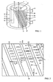
- FIG. 1 illustrates a screen according to a preferred embodiment of the invention, which screen comprises an essentially cylindrical outer casing 1, to which casing a fiber suspension inlet conduit 2, an accept outlet conduit 3 and a reject outlet conduit 4 are connected, a screen drum 5 and one or more stationary blades 6 inside the screen drum 5, which extend in the vicinity of the screen drum's surface.
- the rotating screen drum 5 is attached in a way known per se to a shaft 7 functioning e.g. by belt drive (not shown).
- the space 8 between the screen drum 5 and the outer casing 1 is annular.
- the above mentioned conduits 2 and 4 are connected to the outer casing 1 of the annular space.
- the fiber suspension is fed into the space 8 and the accept flown through the screening surface is discharged from the interior of the screen drum.
- the blades 6 are attached by means of arms 9 to a stationary frame 10, which also forms a support for the shaft 7 via bearings.
- the blades 6 are located inside the drum 5.
- said blades generate a suitable impulse, positive and negative, onto the drum 5, thus cleaning the screening surface of the drum.
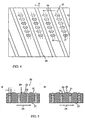
- Figure 2 illustrates a straightened screening surface profile according to a preferred embodiment.
- the profile plate 20 is formed of apertures 21 and profiles 22 between them.
- the apertures 21 are slots in accordance with the invention.
- the form of the slots is rectangular, whereby the edges of their ends can be either rectangular or rounded.
- the ratio of the length L and width W of the slots is 1.05-10, preferably 2-8, depending on the object of application.
- the width W is typically 4-12 mm.
- the longitudinal direction 23 of the slots 21 is parallel to the direction 24 of rotation of the drum 5.
- slots are arranged one above another, whereby rows/zones 11 of slots are formed at a distance from each other in the circumferential direction of the drum.
- the profile ridges 22 and the vertical rows of slots are not aligned with respect to the vertical axis of the drum, but they are declined rows.
- the ridges and rows of slots are at an angle of -5...+20 degrees, typically 15 degrees, angle ⁇ , with respect to the vertical shaft 7 of the drum.
- the slots of the vertical rows 11 of slots can be arranged in the horizontal direction so that they form parallel horizontal rows.
- Figure 2 illustrates an alternative embodiment, where the slots 21 of the vertical rows 11 of slots are in the horizontal direction arranged so that the slots of every second row of slots are located on the same horizontal lines.
- the slots of the vertical rows of slots are in the horizontal direction arranged so that the slots of every second vertical row 11 of slots are located on the same horizontal lines, i.e. in a first group of horizontal lines, and respectively the slots of every second row of slots are located in a second group of horizontal lines.
- the longitudinal direction/longitudinal axis 23 of the slots 21 is at an angle ⁇ with respect to the direction 24 of rotation of the drum, which angle is between -40 and +40 degrees.
- the angle ⁇ is approximately +25 degrees and in Figure 3b approximately -24 degrees.
- Figure 4 illustrates profiles of the outer surface of the plate 20.
- the screening surface can be regarded to be formed of a plate with ridges 22 and planar portions 26 therebetween, which are provided with machined apertures 21.
- profile ridges are additionally provided in the zone of slots so that ridges 25 are arranged between slots located one above another.
- the profile is formed by a row of ridges broken by slots.
- the slot zone may be provided with one or more thus formed profiles, which are preferably at the same declination angle with respect to the vertical axis of the drum as the rows/zones 11 of slots and the profiles 22 between them.
- Figure 5a and b illustrate a screening surface profile as a straightened and cut side view.
- the inner surface 27 plate 20 is flat, except for the apertures.
- the outer surface profile ridge 22 of the plate 20 is formed of front surfaces 29 ascending at a certain angle from the plane 28 of the plate 20, surfaces 30 essentially parallel to the plane 28 of the plate 20, rear surfaces 31 essentially perpendicular to the plane 28 of the plate 20 and portions of the plane 28 between the apertures 21.
- the screen plate can be regarded as being formed of a plate provided with ridges 22 formed of said parts 29, 30 and 31, and between them planar parts 28 provided with machined apertures 21.
- the front surface 29 is perpendicular against the plane 28 of the plate and the rear surface is declined.
- the declined front surface receives the pulp entering the drum, aiming e.g. to accelerate its speed, but an even flow through the screening surface apertures in the screening surface is obtained anyway. This eliminates disturbing flow of the suspension in the opposite direction, which happens under some circumstances.
- the front surface of the profile ridge is perpendicular against the plane of the screening surface and the rear surface of the ridge is descending ( Figure 5a ) the front surface resists and mixes the flow, whereby the flow through the screening surface increases, and thus the capacity of the apparatus increases.
- the ridges 22 are somewhat declined with respect to the axis of the drum, as well as with respect to the direction of rotation of the drum.
- the direction of the ridges 22 has the influence that if the ridges 22 on the screen drum 5 are declined backwards, they tend to lift the fiber suspension upwards on the screen drum, whereby the circulation time of the fiber suspension in the screen is increased, separation becomes more exact and the reject amount is decreased while the accept amount is increased.
- the circulation time is decreased and the capacity is increased.
- the height of the screen drum has an influence on the operational speeds, declination angles etc.
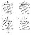
- the position of the longitudinal direction 23 of the slots 21 in one row of slots with respect to the direction 24 of rotation of the drum changes from up downwards seen along the shaft 7 of the drum ( Figure 6a ).
- the longitudinal direction of the uppermost slot 21' is parallel to the direction of rotation of the drum (i.e. perpendicular with respect to the axis of the drum).
- the longitudinal direction of a next lower slot 21" is declined (with respect to the axis of the drum), starting from the front end 32 of the slot in the direction of rotation of the drum, whereby the front end 32 of the slot is located higher than its trailing end 33 (in the direction of rotation of the drum).
- the next lower slot is declined downwards more than the upper one.
- the declination angle of the lower slot is typically 1-5 degrees, typically 2-4 degrees larger.
- the change in the direction of the slots can be regarded as descending from above downwards.
- the longitudinal direction of the uppermost slot is also parallel to the direction of rotation of the drum, while a following lower slot is declined upwards with respect to the direction of rotation, whereby the front end 32' of said slot, in the direction of rotation of the drum, is located lower than its trailing end 33'.
- the next lower slot is declined at the trailing end upwards to a greater extent than the upper slot.
- the declination angle of the lower slot is 1-5, typically 2-4 degrees larger.
- the change in the direction of the slots can be regarded as ascending from above downwards.
- two slots located one above another can be essentially parallel, but it is pertinent that most of the slots in a row of slots are located at different declination angles with respect to each other.
- the position/angle of the longitudinal direction of the slots in one row of slots with respect to the direction of rotation of the drum changes from down upwards seen along the drum's axis so that the longitudinal direction of the lowermost slot is parallel to the direction of rotation of the drum, while a slot located next above is declined with respect to the direction of rotation.
- the next upper slot can be declined upwards ( Figure 6c ), whereby the front end 32" of the slot in the direction of rotation of the drum is located lower than the trailing end 33" of the slot.
- the upper slot is more declined than the lower slot.
- the declination angle of the upper slot is 1-5, typically 2-4 degrees larger.
- the change in the direction of the slots can be regarded as from down upwards ascending.
- an upper slot can be declined correspondingly so that the front end 32"' of the slot in the direction of rotation of the drum is located higher than the trailing end 33"' of the slot. In that case, the slots are declined downwards with respect to the direction of rotation.
- the change in the direction of the slots can be regarded as from down upwards descending.
Landscapes
- Engineering & Computer Science (AREA)
- Mechanical Engineering (AREA)
- Paper (AREA)
- Combined Means For Separation Of Solids (AREA)
Claims (15)
- Vorrichtung zum Sieben einer Fasersuspension, insbesondere zum Entfernen von groben Partikel, wie Knoten, mit
einem Gehäuse (1),
einer Zuführleitung (2) für die Fasersuspension und Auslassleitungen (4, 3) für Spuckstoffe und Gutstoffe, und
einer Siebtrommel (5), die bezüglich der vertikalen Achse (7) drehbar innerhalb des Gehäuses angeordnet ist und eine Siebfläche (20) aufweist, die mit Öffnungen (21) versehen ist, durch welche die Gutstofffraktion strömt, wobei
in der Vorrichtung die Zuführ- und Auslassleitungen so angeordnet sind, dass die Fasersuspension einem Raum (8) zwischen dem Gehäuse und der Siebtrommel zugeführt wird, und der Gutstoff aus dem Inneren der Siebtrommel abgegeben wird,
wobei
die Öffnungen in der Siebfläche Schlitze (21) sind, die Schlitze Schlitzreihen (11) ausbilden, und die äußere Seite der Siebfläche so profiliert ist, dass Rippen (22) zwischen den Schlitzreihen angeordnet sind,
dadurch gekennzeichnet, dass
die Schlitze (21) eine Längsrichtung bezüglich der Drehrichtung der Trommel zwischen -40 und +40 Grad, und ein Verhältnis von Länge zu Breite zwischen 1,05 und 10 aufweisen. - Vorrichtung nach Anspruch 1, bei der
die Längsrichtung der Schlitze (23) zwischen -30 und +30 Grad, vorzugsweise zwischen -15 und +15 Grad bezüglich der Drehrichtung der Trommel liegt. - Vorrichtung nach Anspruch 1 oder 2, bei der
die Längsrichtung der Schlitze (21) parallel zu der Drehrichtung der Trommel ist. - Vorrichtung nach einem der vorhergehenden Ansprüche, bei der
die Schlitze (21) in der vertikalen Richtung übereinander liegen. - Vorrichtung nach einem der vorhergehenden Ansprüche, bei der
das Verhältnis von Länge zu Breite der Schlitze (21) 2-8 beträgt. - Vorrichtung nach einem der vorhergehenden Ansprüche, bei der
Profilrippen (22) so angeordnet sind, dass sie in einem Winkel von -5...+20 Grad, vorzugsweise +15 Grad zu der vertikale Achse (7) der Siebtrommel stehen. - Vorrichtung nach Anspruch 6, bei der
die übereinander angeordneten Schlitze (21) vertikale Reihen von Schlitzen ausbilden, wobei die Enden der Schlitze eine Linie ausbilden, die parallel zu den Profilrippen (22) liegt. - Vorrichtung nach einem der vorhergehenden Ansprüche, bei der
die Schlitze (21) der vertikalen Reihen (11) von Schlitzen so in der horizontalen Richtung angeordnet sind, dass sich die Schlitze jeder zweiten vertikalen Reihe von Schlitzen auf der selben horizontalen Linie liegen, d.h. in einer ersten Gruppe von horizontalen Linien, und die Schlitze jeder zweiten Reihe von Schlitzen entsprechend in einer zweiten Gruppe von horizontalen Linien angeordnet sind. - Vorrichtung nach Anspruch 6 oder 7, bei der
die Außenseite der Siebfläche (20) so profiliert ist, dass eine oder mehrere Rippen (25) im Bereich der Schlitze, auch zwischen den übereinander angeordneten Schlitzen, vorgesehen sind. - Vorrichtung nach einem der vorhergehenden Ansprüche, bei der,
das Profil aus Rippen (22, 25), die eine Vorderseite (29) und eine Rückseite (31), unter einem bestimmten Winkel bezüglich der Siebflächenebene, und eventuell dazwischen eine Fläche (30), die im Wesentlichen parallel zu der Ebene der Platte ist, aufweisen. - Vorrichtung nach Anspruch 10, bei der
die Vorderseite (29) der Profilrippe, welche die Strömung aufnimmt, nach hinten geneigt ist, d.h., dass diese von der Siebflächenebene ansteigt und die Rückseite (31) senkrecht ist. - Vorrichtung nach Anspruch 10, bei der
die Vorderseite (29) der Profilrippe senkrecht zu der Siebflächenebene steht und die Rückseite (31) geneigt ist. - Vorrichtung nach Anspruch 10, bei der
die Vorderseite und die Rückseite der Profilrippe geneigt sind. - Vorrichtung nach einem der vorhergehenden Ansprüche, bei der
sich die Längsposition (23) der Schlitze (21', 21"), die in einer Reihe (11) von Schlitzen bezüglich der Drehrichtung (24) der Trommel angeordnet sind, von oben nach unten betrachtet entlang der Achse der Trommel ändert. - Vorrichtung nach Anspruch 14, bei der
die Längsposition eines Schlitzes (21") in einer Reihe von Schlitzen mehr geneigt ist als die Längsposition eines oberen oder unteren Schlitzes (21').
Applications Claiming Priority (2)
| Application Number | Priority Date | Filing Date | Title |
|---|---|---|---|
| FI20095769A FI20095769A7 (fi) | 2009-07-07 | 2009-07-07 | Laite kuitususpension käsittelemiseksi |
| PCT/FI2010/050482 WO2011004060A1 (en) | 2009-07-07 | 2010-06-10 | Apparatus for screening fibre suspensions |
Publications (3)
| Publication Number | Publication Date |
|---|---|
| EP2452012A1 EP2452012A1 (de) | 2012-05-16 |
| EP2452012A4 EP2452012A4 (de) | 2012-12-05 |
| EP2452012B1 true EP2452012B1 (de) | 2014-01-15 |
Family
ID=40935850
Family Applications (1)
| Application Number | Title | Priority Date | Filing Date |
|---|---|---|---|
| EP10796769.7A Not-in-force EP2452012B1 (de) | 2009-07-07 | 2010-06-10 | Vorrichtung zum screening von fasersuspensionen |
Country Status (7)
| Country | Link |
|---|---|
| EP (1) | EP2452012B1 (de) |
| JP (1) | JP2012532999A (de) |
| CN (1) | CN102472008A (de) |
| BR (1) | BRPI1014007A2 (de) |
| FI (1) | FI20095769A7 (de) |
| RU (1) | RU2012104023A (de) |
| WO (1) | WO2011004060A1 (de) |
Families Citing this family (3)
| Publication number | Priority date | Publication date | Assignee | Title |
|---|---|---|---|---|
| KR101438798B1 (ko) * | 2012-02-08 | 2014-09-05 | 서울대학교산학협력단 | 매크로셀펨토셀 기지국 간 협력 운용 방법 |
| JP6248616B2 (ja) * | 2013-12-25 | 2017-12-20 | セイコーエプソン株式会社 | シート製造装置 |
| AU2019312125B2 (en) * | 2018-07-27 | 2024-09-12 | Accelerated Filtration, Inc. | Filter screen |
Family Cites Families (9)
| Publication number | Priority date | Publication date | Assignee | Title |
|---|---|---|---|---|
| US1631585A (en) * | 1927-06-07 | Screen plate | ||
| US3713541A (en) * | 1971-05-10 | 1973-01-30 | Bird Machine Co | Screening machine with slotted screen |
| SE450711B (sv) * | 1985-11-14 | 1987-07-20 | Besam Ag | Silorgan |
| FI76139C (fi) * | 1987-01-19 | 1988-09-09 | Ahlstroem Oy | Foerfarande och anordning foer kvistseparering. |
| US4795560A (en) * | 1987-04-16 | 1989-01-03 | The Black Clawson Company | Screen plates |
| CN2069430U (zh) * | 1990-07-20 | 1991-01-16 | 上海造纸机械总厂沪光分厂 | 异形筛板 |
| FI89521C (fi) * | 1991-10-04 | 1993-10-11 | Cae Investments Bv | Foerfarande foer framstaellning av en silprodukt och genom foerfarandet framstaelld silprodukt |
| DE10217926A1 (de) * | 2002-04-23 | 2003-11-13 | Voith Paper Patent Gmbh | Verfahren zum Nasssieben von Faserstoffsuspensionen |
| DE502006008007D1 (de) * | 2005-10-19 | 2010-11-18 | Voith Patent Gmbh | Siebvorrichtung zur Nasssiebung von Papierfasersuspensionen |
-
2009
- 2009-07-07 FI FI20095769A patent/FI20095769A7/fi not_active IP Right Cessation
-
2010
- 2010-06-10 BR BRPI1014007A patent/BRPI1014007A2/pt not_active IP Right Cessation
- 2010-06-10 CN CN2010800306089A patent/CN102472008A/zh active Pending
- 2010-06-10 JP JP2012519028A patent/JP2012532999A/ja not_active Abandoned
- 2010-06-10 RU RU2012104023/12A patent/RU2012104023A/ru not_active Application Discontinuation
- 2010-06-10 WO PCT/FI2010/050482 patent/WO2011004060A1/en not_active Ceased
- 2010-06-10 EP EP10796769.7A patent/EP2452012B1/de not_active Not-in-force
Also Published As
| Publication number | Publication date |
|---|---|
| WO2011004060A1 (en) | 2011-01-13 |
| EP2452012A4 (de) | 2012-12-05 |
| FI20095769L (fi) | 2011-01-08 |
| FI20095769A7 (fi) | 2011-01-08 |
| BRPI1014007A2 (pt) | 2016-04-12 |
| EP2452012A1 (de) | 2012-05-16 |
| RU2012104023A (ru) | 2013-08-20 |
| JP2012532999A (ja) | 2012-12-20 |
| FI20095769A0 (fi) | 2009-07-07 |
| CN102472008A (zh) | 2012-05-23 |
Similar Documents
| Publication | Publication Date | Title |
|---|---|---|
| CA1174203A (en) | Pump and clearing-type wedge-shaped vanes on antiblinding rotating drums for screens | |
| JP4048258B2 (ja) | 古紙パルプの選別装置 | |
| JPS5841889B2 (ja) | 繊維浮遊液体のふるい分け方法及びその方法を実施する加圧ふるい分け装置 | |
| WO1994023848A1 (en) | Screening apparatus for papermaking pulp | |
| EP2452012B1 (de) | Vorrichtung zum screening von fasersuspensionen | |
| GB1566468A (en) | Apparatus for screening paper fibre stock | |
| CA1064428A (en) | Stationary cylindrical screen for liquid suspensions including a heavy impurities trap and dilution means | |
| US20140158586A1 (en) | Pulp screen rotor with slurry passages around and through the rotor | |
| CA2060074C (en) | Apparatus for treating fiber suspension | |
| US3970548A (en) | Apparatus for screening paper fiber stock | |
| CA1092549A (en) | Vortex separator with coaxial inlet and lightweight reject pipelines | |
| US8950584B2 (en) | Apparatus for screening fibrous suspensions | |
| US12509824B2 (en) | Pulp screening machine | |
| CN103687991B (zh) | 压力筛浆机 | |
| FI109038B (fi) | Menetelmä kuitumassaseoksen käsittelemiseksi ja lajitin | |
| JPH07308598A (ja) | スクリーン選別装置用ロータおよびスクリーン選別装置 | |
| MXPA01001292A (es) | Criba. | |
| AT408771B (de) | Sortierer zur reinigung einer faserstoffsuspension | |
| US20050258079A1 (en) | Pressurized screen for screening a fibrous suspension and use thereof | |
| DE10233364C1 (de) | Drucksortierer zum Sieben einer Faserstoffsuspension | |
| CA1329333C (en) | Method and apparatus for separating knots | |
| WO2004046457A1 (en) | Method and apparatus for treating fiber suspension | |
| EP2994568B1 (de) | Vorrichtung zum trennen von partikeln in einer faserstoffsuspension | |
| MXPA01001294A (es) | Criba. | |
| US4927529A (en) | Method and apparatus for separating knots |
Legal Events
| Date | Code | Title | Description |
|---|---|---|---|
| PUAI | Public reference made under article 153(3) epc to a published international application that has entered the european phase |
Free format text: ORIGINAL CODE: 0009012 |
|
| 17P | Request for examination filed |
Effective date: 20120125 |
|
| AK | Designated contracting states |
Kind code of ref document: A1 Designated state(s): AL AT BE BG CH CY CZ DE DK EE ES FI FR GB GR HR HU IE IS IT LI LT LU LV MC MK MT NL NO PL PT RO SE SI SK SM TR |
|
| DAX | Request for extension of the european patent (deleted) | ||
| A4 | Supplementary search report drawn up and despatched |
Effective date: 20121102 |
|
| RIC1 | Information provided on ipc code assigned before grant |
Ipc: D21D 5/06 20060101ALI20121026BHEP Ipc: D21D 5/16 20060101AFI20121026BHEP |
|
| GRAP | Despatch of communication of intention to grant a patent |
Free format text: ORIGINAL CODE: EPIDOSNIGR1 |
|
| INTG | Intention to grant announced |
Effective date: 20130806 |
|
| GRAS | Grant fee paid |
Free format text: ORIGINAL CODE: EPIDOSNIGR3 |
|
| GRAA | (expected) grant |
Free format text: ORIGINAL CODE: 0009210 |
|
| AK | Designated contracting states |
Kind code of ref document: B1 Designated state(s): AL AT BE BG CH CY CZ DE DK EE ES FI FR GB GR HR HU IE IS IT LI LT LU LV MC MK MT NL NO PL PT RO SE SI SK SM TR |
|
| REG | Reference to a national code |
Ref country code: GB Ref legal event code: FG4D Ref country code: CH Ref legal event code: EP |
|
| REG | Reference to a national code |
Ref country code: AT Ref legal event code: REF Ref document number: 649906 Country of ref document: AT Kind code of ref document: T Effective date: 20140215 |
|
| REG | Reference to a national code |
Ref country code: DE Ref legal event code: R096 Ref document number: 602010013194 Country of ref document: DE Effective date: 20140220 |
|
| REG | Reference to a national code |
Ref country code: IE Ref legal event code: FG4D |
|
| REG | Reference to a national code |
Ref country code: NL Ref legal event code: VDEP Effective date: 20140115 |
|
| REG | Reference to a national code |
Ref country code: AT Ref legal event code: MK05 Ref document number: 649906 Country of ref document: AT Kind code of ref document: T Effective date: 20140115 |
|
| REG | Reference to a national code |
Ref country code: LT Ref legal event code: MG4D |
|
| PG25 | Lapsed in a contracting state [announced via postgrant information from national office to epo] |
Ref country code: IS Free format text: LAPSE BECAUSE OF FAILURE TO SUBMIT A TRANSLATION OF THE DESCRIPTION OR TO PAY THE FEE WITHIN THE PRESCRIBED TIME-LIMIT Effective date: 20140515 Ref country code: NO Free format text: LAPSE BECAUSE OF FAILURE TO SUBMIT A TRANSLATION OF THE DESCRIPTION OR TO PAY THE FEE WITHIN THE PRESCRIBED TIME-LIMIT Effective date: 20140415 Ref country code: LT Free format text: LAPSE BECAUSE OF FAILURE TO SUBMIT A TRANSLATION OF THE DESCRIPTION OR TO PAY THE FEE WITHIN THE PRESCRIBED TIME-LIMIT Effective date: 20140115 |
|
| PG25 | Lapsed in a contracting state [announced via postgrant information from national office to epo] |
Ref country code: NL Free format text: LAPSE BECAUSE OF FAILURE TO SUBMIT A TRANSLATION OF THE DESCRIPTION OR TO PAY THE FEE WITHIN THE PRESCRIBED TIME-LIMIT Effective date: 20140115 Ref country code: CY Free format text: LAPSE BECAUSE OF FAILURE TO SUBMIT A TRANSLATION OF THE DESCRIPTION OR TO PAY THE FEE WITHIN THE PRESCRIBED TIME-LIMIT Effective date: 20140115 Ref country code: SE Free format text: LAPSE BECAUSE OF FAILURE TO SUBMIT A TRANSLATION OF THE DESCRIPTION OR TO PAY THE FEE WITHIN THE PRESCRIBED TIME-LIMIT Effective date: 20140115 Ref country code: AT Free format text: LAPSE BECAUSE OF FAILURE TO SUBMIT A TRANSLATION OF THE DESCRIPTION OR TO PAY THE FEE WITHIN THE PRESCRIBED TIME-LIMIT Effective date: 20140115 Ref country code: ES Free format text: LAPSE BECAUSE OF FAILURE TO SUBMIT A TRANSLATION OF THE DESCRIPTION OR TO PAY THE FEE WITHIN THE PRESCRIBED TIME-LIMIT Effective date: 20140115 Ref country code: PT Free format text: LAPSE BECAUSE OF FAILURE TO SUBMIT A TRANSLATION OF THE DESCRIPTION OR TO PAY THE FEE WITHIN THE PRESCRIBED TIME-LIMIT Effective date: 20140515 Ref country code: FI Free format text: LAPSE BECAUSE OF FAILURE TO SUBMIT A TRANSLATION OF THE DESCRIPTION OR TO PAY THE FEE WITHIN THE PRESCRIBED TIME-LIMIT Effective date: 20140115 |
|
| PG25 | Lapsed in a contracting state [announced via postgrant information from national office to epo] |
Ref country code: LV Free format text: LAPSE BECAUSE OF FAILURE TO SUBMIT A TRANSLATION OF THE DESCRIPTION OR TO PAY THE FEE WITHIN THE PRESCRIBED TIME-LIMIT Effective date: 20140115 Ref country code: BE Free format text: LAPSE BECAUSE OF FAILURE TO SUBMIT A TRANSLATION OF THE DESCRIPTION OR TO PAY THE FEE WITHIN THE PRESCRIBED TIME-LIMIT Effective date: 20140115 Ref country code: HR Free format text: LAPSE BECAUSE OF FAILURE TO SUBMIT A TRANSLATION OF THE DESCRIPTION OR TO PAY THE FEE WITHIN THE PRESCRIBED TIME-LIMIT Effective date: 20140115 |
|
| REG | Reference to a national code |
Ref country code: DE Ref legal event code: R097 Ref document number: 602010013194 Country of ref document: DE |
|
| PG25 | Lapsed in a contracting state [announced via postgrant information from national office to epo] |
Ref country code: EE Free format text: LAPSE BECAUSE OF FAILURE TO SUBMIT A TRANSLATION OF THE DESCRIPTION OR TO PAY THE FEE WITHIN THE PRESCRIBED TIME-LIMIT Effective date: 20140115 Ref country code: CZ Free format text: LAPSE BECAUSE OF FAILURE TO SUBMIT A TRANSLATION OF THE DESCRIPTION OR TO PAY THE FEE WITHIN THE PRESCRIBED TIME-LIMIT Effective date: 20140115 Ref country code: RO Free format text: LAPSE BECAUSE OF FAILURE TO SUBMIT A TRANSLATION OF THE DESCRIPTION OR TO PAY THE FEE WITHIN THE PRESCRIBED TIME-LIMIT Effective date: 20140115 Ref country code: DK Free format text: LAPSE BECAUSE OF FAILURE TO SUBMIT A TRANSLATION OF THE DESCRIPTION OR TO PAY THE FEE WITHIN THE PRESCRIBED TIME-LIMIT Effective date: 20140115 |
|
| PLBE | No opposition filed within time limit |
Free format text: ORIGINAL CODE: 0009261 |
|
| STAA | Information on the status of an ep patent application or granted ep patent |
Free format text: STATUS: NO OPPOSITION FILED WITHIN TIME LIMIT |
|
| PG25 | Lapsed in a contracting state [announced via postgrant information from national office to epo] |
Ref country code: SK Free format text: LAPSE BECAUSE OF FAILURE TO SUBMIT A TRANSLATION OF THE DESCRIPTION OR TO PAY THE FEE WITHIN THE PRESCRIBED TIME-LIMIT Effective date: 20140115 Ref country code: PL Free format text: LAPSE BECAUSE OF FAILURE TO SUBMIT A TRANSLATION OF THE DESCRIPTION OR TO PAY THE FEE WITHIN THE PRESCRIBED TIME-LIMIT Effective date: 20140115 |
|
| 26N | No opposition filed |
Effective date: 20141016 |
|
| REG | Reference to a national code |
Ref country code: DE Ref legal event code: R119 Ref document number: 602010013194 Country of ref document: DE |
|
| PG25 | Lapsed in a contracting state [announced via postgrant information from national office to epo] |
Ref country code: MC Free format text: LAPSE BECAUSE OF FAILURE TO SUBMIT A TRANSLATION OF THE DESCRIPTION OR TO PAY THE FEE WITHIN THE PRESCRIBED TIME-LIMIT Effective date: 20140115 Ref country code: LU Free format text: LAPSE BECAUSE OF FAILURE TO SUBMIT A TRANSLATION OF THE DESCRIPTION OR TO PAY THE FEE WITHIN THE PRESCRIBED TIME-LIMIT Effective date: 20140610 |
|
| REG | Reference to a national code |
Ref country code: CH Ref legal event code: PL |
|
| REG | Reference to a national code |
Ref country code: DE Ref legal event code: R097 Ref document number: 602010013194 Country of ref document: DE Effective date: 20141016 |
|
| GBPC | Gb: european patent ceased through non-payment of renewal fee |
Effective date: 20140610 |
|
| REG | Reference to a national code |
Ref country code: IE Ref legal event code: MM4A |
|
| REG | Reference to a national code |
Ref country code: DE Ref legal event code: R119 Ref document number: 602010013194 Country of ref document: DE Effective date: 20150101 |
|
| REG | Reference to a national code |
Ref country code: FR Ref legal event code: ST Effective date: 20150227 |
|
| PG25 | Lapsed in a contracting state [announced via postgrant information from national office to epo] |
Ref country code: CH Free format text: LAPSE BECAUSE OF NON-PAYMENT OF DUE FEES Effective date: 20140630 Ref country code: IE Free format text: LAPSE BECAUSE OF NON-PAYMENT OF DUE FEES Effective date: 20140610 Ref country code: LI Free format text: LAPSE BECAUSE OF NON-PAYMENT OF DUE FEES Effective date: 20140630 Ref country code: DE Free format text: LAPSE BECAUSE OF NON-PAYMENT OF DUE FEES Effective date: 20150101 |
|
| PG25 | Lapsed in a contracting state [announced via postgrant information from national office to epo] |
Ref country code: FR Free format text: LAPSE BECAUSE OF NON-PAYMENT OF DUE FEES Effective date: 20140630 Ref country code: GB Free format text: LAPSE BECAUSE OF NON-PAYMENT OF DUE FEES Effective date: 20140610 Ref country code: SI Free format text: LAPSE BECAUSE OF FAILURE TO SUBMIT A TRANSLATION OF THE DESCRIPTION OR TO PAY THE FEE WITHIN THE PRESCRIBED TIME-LIMIT Effective date: 20140115 |
|
| PG25 | Lapsed in a contracting state [announced via postgrant information from national office to epo] |
Ref country code: MT Free format text: LAPSE BECAUSE OF FAILURE TO SUBMIT A TRANSLATION OF THE DESCRIPTION OR TO PAY THE FEE WITHIN THE PRESCRIBED TIME-LIMIT Effective date: 20140115 |
|
| PG25 | Lapsed in a contracting state [announced via postgrant information from national office to epo] |
Ref country code: SM Free format text: LAPSE BECAUSE OF FAILURE TO SUBMIT A TRANSLATION OF THE DESCRIPTION OR TO PAY THE FEE WITHIN THE PRESCRIBED TIME-LIMIT Effective date: 20140115 |
|
| PG25 | Lapsed in a contracting state [announced via postgrant information from national office to epo] |
Ref country code: GR Free format text: LAPSE BECAUSE OF FAILURE TO SUBMIT A TRANSLATION OF THE DESCRIPTION OR TO PAY THE FEE WITHIN THE PRESCRIBED TIME-LIMIT Effective date: 20140416 Ref country code: IT Free format text: LAPSE BECAUSE OF FAILURE TO SUBMIT A TRANSLATION OF THE DESCRIPTION OR TO PAY THE FEE WITHIN THE PRESCRIBED TIME-LIMIT Effective date: 20140115 Ref country code: BG Free format text: LAPSE BECAUSE OF FAILURE TO SUBMIT A TRANSLATION OF THE DESCRIPTION OR TO PAY THE FEE WITHIN THE PRESCRIBED TIME-LIMIT Effective date: 20140115 |
|
| PG25 | Lapsed in a contracting state [announced via postgrant information from national office to epo] |
Ref country code: TR Free format text: LAPSE BECAUSE OF FAILURE TO SUBMIT A TRANSLATION OF THE DESCRIPTION OR TO PAY THE FEE WITHIN THE PRESCRIBED TIME-LIMIT Effective date: 20140115 Ref country code: HU Free format text: LAPSE BECAUSE OF FAILURE TO SUBMIT A TRANSLATION OF THE DESCRIPTION OR TO PAY THE FEE WITHIN THE PRESCRIBED TIME-LIMIT; INVALID AB INITIO Effective date: 20100610 |
|
| PG25 | Lapsed in a contracting state [announced via postgrant information from national office to epo] |
Ref country code: MK Free format text: LAPSE BECAUSE OF FAILURE TO SUBMIT A TRANSLATION OF THE DESCRIPTION OR TO PAY THE FEE WITHIN THE PRESCRIBED TIME-LIMIT Effective date: 20140115 |
|
| PG25 | Lapsed in a contracting state [announced via postgrant information from national office to epo] |
Ref country code: AL Free format text: LAPSE BECAUSE OF FAILURE TO SUBMIT A TRANSLATION OF THE DESCRIPTION OR TO PAY THE FEE WITHIN THE PRESCRIBED TIME-LIMIT Effective date: 20140115 |