EP2451208A1 - Wireless communication rate shaping - Google Patents
Wireless communication rate shaping Download PDFInfo
- Publication number
- EP2451208A1 EP2451208A1 EP11009729A EP11009729A EP2451208A1 EP 2451208 A1 EP2451208 A1 EP 2451208A1 EP 11009729 A EP11009729 A EP 11009729A EP 11009729 A EP11009729 A EP 11009729A EP 2451208 A1 EP2451208 A1 EP 2451208A1
- Authority
- EP
- European Patent Office
- Prior art keywords
- rate
- data rates
- reverse link
- transition probabilities
- data rate
- Prior art date
- Legal status (The legal status is an assumption and is not a legal conclusion. Google has not performed a legal analysis and makes no representation as to the accuracy of the status listed.)
- Withdrawn
Links
Images


Classifications
-
- H—ELECTRICITY
- H04—ELECTRIC COMMUNICATION TECHNIQUE
- H04B—TRANSMISSION
- H04B7/00—Radio transmission systems, i.e. using radiation field
- H04B7/005—Control of transmission; Equalising
-
- H—ELECTRICITY
- H04—ELECTRIC COMMUNICATION TECHNIQUE
- H04W—WIRELESS COMMUNICATION NETWORKS
- H04W28/00—Network traffic management; Network resource management
- H04W28/16—Central resource management; Negotiation of resources or communication parameters, e.g. negotiating bandwidth or QoS [Quality of Service]
- H04W28/18—Negotiating wireless communication parameters
- H04W28/22—Negotiating communication rate
-
- H—ELECTRICITY
- H04—ELECTRIC COMMUNICATION TECHNIQUE
- H04W—WIRELESS COMMUNICATION NETWORKS
- H04W16/00—Network planning, e.g. coverage or traffic planning tools; Network deployment, e.g. resource partitioning or cells structures
- H04W16/02—Resource partitioning among network components, e.g. reuse partitioning
- H04W16/10—Dynamic resource partitioning
-
- H—ELECTRICITY
- H04—ELECTRIC COMMUNICATION TECHNIQUE
- H04W—WIRELESS COMMUNICATION NETWORKS
- H04W72/00—Local resource management
- H04W72/50—Allocation or scheduling criteria for wireless resources
- H04W72/54—Allocation or scheduling criteria for wireless resources based on quality criteria
-
- H—ELECTRICITY
- H04—ELECTRIC COMMUNICATION TECHNIQUE
- H04W—WIRELESS COMMUNICATION NETWORKS
- H04W24/00—Supervisory, monitoring or testing arrangements
Definitions
- the present invention relates generally to wireless communication, and particularly to reverse link rate allocation for packet data transmissions.
- a radio link for transmissions from an Access Network (AN), or system infrastructure, to an Access Terminal, or remote user is referred to as a downlink or Forward Link (FL).
- the radio link for transmissions from the AT to the AN is referred to as the uplink or Reverse Link (RL).
- RL Reverse Link
- Each AT determines an appropriate data rate for RL transmissions.
- Various methods for determining RL transmission rates from an AT are discussed in "SYSTEM AND METHOD FOR PERSISTENCE-VECTOR-BASED MODIFICATION OF USAGE RATES," by Rajesh Pankaj, et al., having U.S. Patent Application No. 09/410,199, filed on September 30, 1999 , and assigned to the assignee hereof.
- the AT autonomously determines a data rate for transmissions on the RL based on a probabilistic algorithm that considers the amount of data pending, the available transmit power or PA (power amplifier) headroom, the closed loop resource allocation calculation, and the maximum data rate as indicated to the AT by the AN.
- the AN assigns probabilities to each of the possible rate transitions that an AT may make.
- Each AT uses the same probabilities, which are predetermined and set at each AT.
- each AT implements a power control mechanism to adjust the transmit power dynamically.
- the adjust in AT transmit power compensates for changes in AT location, shadowing and fading experienced by the AT and the transmit data rate.
- BS Base Station
- AS Active Set
- the transmit power of the AT increases to compensate.
- the interference caused by the AT in question to other AT's is increased due to an increase in the AT transmit power.
- an AT far from the AN, or otherwise experiencing a poor channel condition, relative to other ATs may be subject to low data rates for an extended time period.
- there is a desire to provide an equal grade of service In other words, each AT is provided an approximately equal opportunity to transmit data on the RL without regard to channel condition so as not to penalize an AT for moving within the system.
- this mechanism does not take into account the interference due to an AT.
- An increase in data rate results in an increase in the interference caused by an AT to other ATs in the system and therefore, there is a desire to discourage and/or prohibit that AT from transmitting at higher rates if that AT is likely to cause excessive interference to other AT's in the system. Further, there is a desire for each AT to transmit at maximum rate conditioned on equal interference considering all ATs in the system.
- AT rate allocation that balances an equal grade of service goal with the desire to maximize capacity of the system.
- AT rate allocation that provides a robust RL and reduces interference to other users.
- reverse link rate allocation to achieve better control over other-cell interference and improve system stability.
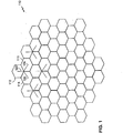
- FIG. 1 is a cellular communication system supporting packetized data transmissions.
- FIG. 2A is an illustration of a throughput profile as a function of forward link channel quality for multiple access terminals.
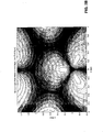
- FIG. 2B is an illustration of a rate profile for the reverse link in a wireless communication system.
- FIG. 3 is a table of data rates available in a communication system.
- FIG. 4 is an illustration of transition probabilities used for reverse link rate allocation in a communication system.
- FIG. 5 is a graph of reverse activity bits in a high data rate communication system.
- FIG. 6 is an illustration of transition probabilities in a wireless communication system.
- FIG. 7 is a table for determining a maximum reverse link data rate as a function of forward link signal to interference and noise ratio.
- FIG. 8 is an Access Terminal.
- FIG. 9 is an infrastructure element of an Access Network.
- the field of wireless communications has many applications including, e.g., cordless telephones, paging, wireless local loops, Personal Digital Assistants (PDAs), Internet telephony, and satellite communication systems.
- a particularly important application is cellular telephone systems for mobile subscribers.
- the term "cellular" system encompasses both cellular and Personal Communication Services (PCS) frequencies.
- PCS Personal Communication Services
- Various over-the-air interfaces have been developed for such cellular telephone systems including, e.g., Frequency Division Multiple Access (PDMA), Time Division Multiple Access (TDMA), and Code Division Multiple Access (CDMA).
- PDMA Frequency Division Multiple Access
- TDMA Time Division Multiple Access
- CDMA Code Division Multiple Access
- various domestic and international standards have been established including, e.g., Advanced Mobile Phone Service (AMPS), Global System for Mobile (GSM), and Interim Standard 95 (IS-95).
- AMPS Advanced Mobile Phone Service
- GSM Global System for Mobile
- IS-95 Interim Standard 95
- IS-95A IS-95A
- IS-95B IS-95B
- ANSI J-STD-008 ANSI J-STD-008
- TIA Telecommunication Industry Association
- Cellular telephone systems configured in accordance with the use of the IS-95 standard employ CDMA signal processing techniques to provide highly efficient and robust cellular telephone service.
- Exemplary cellular telephone systems configured substantially in accordance with the use of the IS-95 standard are described in U.S. Patent Nos. 5,103,459 and 4,901,307 , which are assigned to the assignee of the present invention.
- An exemplary system utilizing CDMA techniques is the cdma2000 ITU-R Radio Transmission Technology (RTT) Candidate submission (referred to herein as cdma2000), issued by the TIA.
- RTT Radio Transmission Technology
- CDMA standard is the W-CDMA standard, as embodied in 3 rd Generation Partnership Project "3GPP" , Document Nos. 3G TS 25.211, 3G TS 25.212, 3G TS 25.213, and 3G TS 25.214.
- 3GPP 3 rd Generation Partnership Project
- the telecommunication standards cited above are examples of only some of the various communication systems that can be implemented.
- FIG. 1 illustrates a cellular communication system 100 according to one embodiment.
- the system 100 includes multiple cells, each covering a geographical area. Each of the multiple cells includes multiple sectors.
- cell 110 includes the sectors 112, 114, and 116. Each of the sectors is defined by an antenna.
- the antenna element 120 is directed within the sector 112; the antenna element 122 is directed within the sector 114; and the antenna element 124 is directed within the sector 116. Examples of further antenna structures and base station arrangements are illustrated in FIG. 1 .
- the system 100 is provided as an example for the following discussion. Note that alternate systems may implement alternate arrangements and configurations, wherein the number of antenna elements per sector and the number of sectors per cell may vary. Note that alternate embodiments may have different terminology for similar functional units, and may incorporate different configurations of components and functional units.
- FIG. 2A illustrates a plot of the throughput for each of multiple ATs in the system 100 as a function of an associated FL channel quality.
- the shape of the plot reflects a RL profile for the ATs in the system.
- the throughput of an AT is approximately proportional to the serving sector FL Signal-to-Interference and Noise Ratio (SINR).
- SINR Signal-to-Interference and Noise Ratio
- the RL rate shaping can be based on criteria other than FL serving sector SINR.
- the rate shaping criteria may be based on a FL captured SINR (i.e., the sum total of the SINR of all pilots in the active set).
- FIG. 2B illustrates a rate profile for the RL considering multiple sectors and multiple mobile stations or ATs. As illustrated, it's a contour plot of RL rate based on FL SINR in a multi-sector layout. The dark areas correspond to the better channel conditions, wherein the channel condition degrades with distance from the transmitter. The sector boundaries are overlaid to the figure.
- RL rate shaping should not preclude a mobile station from utilizing a given service. For example, videoconferencing may require 64kbps, and therefore, all mobile stations may be allowed to transmit at 76.8kbps as needed. Providing equal Grade of Service may not be a requirement for all systems.
- the desired shape of the profile is determined based on the goals and requirements of a given system. The determination of a desired shape of the profile and the implementation of a rate allocation method to achieve the desired shape is generally referred to as "rate shaping.”
- rate shaping involves dynamic rate allocation at the AT, and specifically modification of the rate allocation algorithm to consider a quality measure of the FL, such as serving sector SINR.
- Such reverse link rate allocation also referred to as rate shaping, limits the interference due to terminals in handoff regions. This is achieved either by limiting the max RL rate or by reducing the likelihood that a terminal in handoff regions transmits at the highest rates, wherein terminals in handoff region are allowed to transmit at the highest rates in the case of an unloaded system.
- the AT implements an algorithm for rate allocation that considers: 1) pending data; 2) available transmit power for traffic as determined based on the difference between the overhead channel transmit power and the maximum transmit power; 3) Closed Loop Resource Allocation (CLRA); and 4) maximum data rate.
- the algorithm determines a data rate associated with each of the four considerations, and selects the minimum rate.
- the AT updates the data rate periodically. In a 1xEV-DO system, the AT updates the data rate every 16 slots, however, alternate systems may implement another scheme for updating the data rate.
- the pending data has an associated data rate, R1, that increases proportionally with the amount of data in a data queue at the AT.
- the CLRA has an associated data rate R3, which is determined based on RL rate transition probabilities.
- the maximum data rate is identified as R4 and may be set by the AN.
- the CLRA limits changes in the data rate, and specifically limits increases so as to avoid large increases in data rates by multiple ATs in quick succession that may overload the system.
- a Reverse Activity Bit (RAB) is a mechanism to identify a RL loaded condition to the AT.
- the RAB mechanism has a delay incurred by the time(s) required for: 1) measurement of the load at the BS; 2) the subsequent transmission of the RAB to terminals; and 3) implementation at the AT to reduce/increase their data rate.
- the data rate R3 associated with the CLRA calculation is determined based on the previous data rate, referred to as R old .
- Two sets of transition probabilities are provided by the AN. Each set assigns a transition probability to each of the allowable data rates. The first set corresponds to transitions that increase the data rate. The second set corresponds to transitions that decrease the data rate.
- FIG. 3 illustrates the rates of one embodiment supporting the 1xEV-DO standard.
- the rate index identifies each corresponding data rate.
- Each successive data rate is twice the previous rate.
- FIG. 4 illustrates the transition probability sets generated in the CLRA calculation. On the top is the first set of transition probabilities, identified as P UP . On the bottom is the second set of transition probabilities, identified as P DN .
- the indices, such as given in FIG. 3 point to the associated transition probabilities in each set.
- the AN transmits a busy bit, referred to as the Reverse link Activity Bit (RAB).
- RAB Reverse link Activity Bit
- FIG. 5 illustrates the RAB values over time for a given AN.
- the RAB may be set or cleared depending on the loading of the AN.
- the RAB is transmitted with a period T RAB .
- the RAB setting (1 or 0) indicates to each AT whether or not the system is loaded.
- the RAB is set to indicate a loaded condition and cleared otherwise. Alternate methods may be implemented for conveying reverse link loading information to the AT.
- the AT receives the RAB (or other indication that the system is loaded)
- the AT has two decision options for rate allocation: 1) decrease the data rate; or 2) maintain the current data rate R OLD .
- the AT applies the second set of transition probabilities.
- the AT selects the transition probability within the second set P DN that corresponds to the current data rate R OLD .
- the AT receives a cleared RAB, or other indication that the system is not loaded, the AT has two decision options for rate allocation: 1) increase the data rate; or 2) maintain the current data rate, R OLD .
- the AT selects a transition probability from the first set P UP .Again the particular transition probability selected corresponds to the current data rate R OLD .
- the AT For each rate allocation update, the AT then generates a random number for comparison to the selected transition probability. The result of the comparison determines which of the two decision options the AT will make. Effectively the transition probability determines the percentage of time a data rate change will be made. Typically, for low data rates the transition probabilities will be higher, wherein any random number less than the transition probability will result in a data rate increase.
- the transition probabilities are generally constrained as: P ⁇ 1 > P ⁇ 2 > P ⁇ 3 > P ⁇ 4 > P ⁇ 5. As illustrated in FIG. 6 , each probability is associated with a specific transition. Alternate probability assignments are also possible, wherein a transition probability may be associated with multiple possible transitions.
- the upper row illustrates the transition probabilities for increases in data rate when the system is determined as not busy.
- the not busy indication may be made by a message or bit from the transmitter on the FL, or may be based on a measurement of channel quality or some other link criteria. FL channel quality considerations are discussed hereinbelow.
- the lower row illustrates the transition probabilities corresponding to decreases in data rates when the system is determined to be busy.
- the busy indication may be made by a message or bit from the transmitter on the FL, or may be based on a measurement of channel quality or some other link criteria.
- the last data rate on the right corresponds to the maximum data rate. In the system discussed herein as an example, the system supports four data rates. It is possible to limit the maximum data rate, in which case the total number of available data rates is reduced.
- the transition probabilities are therefore used to determine a data rate decision of the CLRA calculation.
- the CLRA associated data rate R3 will be R OLD , (R OLD /2), (R OLD *2), limiting the rate change.
- the AT determines the minimum of the data rates R1, R2, R3, and R4, and applies the minimum data rate.
- R NEW min R ⁇ 1 , R ⁇ 2 , R ⁇ 3 , R ⁇ 4
- the rate allocation algorithm is modified to consider the FL serving sector SINR as measured and/or estimated at the AT.
- the FL serving sector SINR is used to limit the maximum data rate allowable for RL transmissions of the AT.
- FIG. 7 illustrates a table identifying the associated maximum data rate for the RL as a function of FL SINR values.
- the illustrated table includes three SINR value ranges: 1) less than 0dB; 2) from 0dB to 4dB; and 3) greater than 4dB. Note that alternate embodiments may implement a different number of ranges, as well as different ranges.
- the mapping of SINR value to maximum RL data rate may be a formula rather than a look up table. Similarly, alternate maximum RL data rates may be implemented. Also indicate that 5 max rate levels can be used as we have 5 defined rates on the RL. It should also be made clear that additional levels may be used if additional rates are added on the RL.
- the system 100 supports the IS-856 standard, and therefore, each AT determines a data rate for the FL as a function of the FL quality, such as by use of the FL SINR.
- the AT then sends a data rate request on a Data Rate Channel (DRC).
- DRC Data Rate Channel
- the DRC data rate request indicates the data rate at which the AT is able to receive data communications.
- the AN uses this information to schedule transmissions to ATs for which data is pending at the AN.
- the DRC data rate request may be used to determine the maximum RL data rate.
- the maximum RL data rate may be limited as a function of the RL channel state.
- the ATs are required to continually transmit a RL pilot signal.
- the RL pilot signal is transmitted on a pilot channel, which is power controlled.
- the RL traffic channel is power controlled based on the RL pilot, i.e., the RL traffic channel power is relative to the pilot channel power and the traffic-channel-to-pilot-channel power ratios are predetermined. Variations on the pilot channel are due to changes in channel conditions. The variations in power on the traffic channel are those on the pilot channel as well as due to the bursty-nature of packet data transmissions.
- RL channel state change i.e., change in RL channel quality.
- Sudden changes in RL channel conditions may result in increased interference to terminals in adjacent sectors.
- This algorithm avoids sudden changes in RL channel conditions from resulting in increased interference by limiting the max. RL transmit rate in case of sudden changes in RL channel conditions, e.g., if the AT transmits at high rates in good channel conditions, sudden degradation in channel condition (which is OK for the RL to the power controlling sector) the AT continuing to transmit at high RL rates may result in higher levels of interference to terminals in adjacent sectors.
- the maximum RL data rate is limited to a given data rate.
- the data rate may be limited to a predetermined data rate or may be calculated as a function of the current data rate, loading of the system, or some other parameter.
- the use of the RL channel state information may be implemented with the FL channel quality information to limit the maximum RL data rate.
- the maximum RL data rate may be limited by the AN, wherein the AN measures the differential Rise-Over-Thermal (ROT) between neighboring sectors.
- a comparison of the ROT for sectors 112 and 114 is performed at a Base Station Controller (BSC) (not shown).
- BSC Base Station Controller
- Each BS sends an ROT value corresponding to the sector served by the BS.
- the BSC may then adjust the maximum RL data rate and/or transition probabilities for Access Terminals (ATs) within the sectors.
- ATs Access Terminals
- the BSC may lower the maximum data rate of the MS.
- the MS is in communication with sector 1, which is not loaded, but is not able to utilize sector 2, which is not loaded. Therefore, unless the MS is limited to a lower maximum data rate it may cause significant interference.
- AS Active Set
- the AT measures the captured SINR which is the sum total of the forward link SINR received at the AT. The captured SINR is used to determine if adjustment is made to the transition probabilities stored at the AT. For captured SINR above a target threshold, the AT may adjust the maximum data rate to allow higher data rates. Conversely, for captured SINR below a target threshold, the AT may adjust the maximum data rate to limit the AT to lower data rates. Two distinct thresholds may be used for the two cases given.
- different sets of RL data rate transition probabilities are assigned to ATs as a function of the FL sector SINR.
- the rate shaping may be implemented adjusting the transition probabilities in response to perceived channel quality. Improved channel quality will result in transition probabilities that encourage increases in RL data rates. Degraded channel quality will result in transition probabilities that encourage decreases in RL data rates.
- Such probabilistic rate shaping may also be applied to maximum RL data rate limiting as a function of SINR.
- Each AT measures the channel quality of the FL received signal.
- the AT may choose to maintain the current values of the transition probabilities, as illustrated in FIG. 6 , or may choose to adjust one or more of the probabilities. For example, if the channel quality measurement, such as an SINR measurement, is above a predetermined threshold, the probabilities may be changed to encourage higher data rates. In other words, the transition probabilities may be modified to increase the probability of making the associated transitions. Similarly, if the channel quality measurement is below another such threshold, the transition probabilities are adjusted to discourage higher data rates.
- each individual transition e.g., p1, p2, etc.
- the AT may adjust the maximum allowable data rate in response to a channel quality measurement. This may result in the addition of data rates, and thus additional transition probabilities for those rates, or may result in the elimination of data rates, and thus the elimination of the transitional probabilities associated with the eliminated data rates. For example, as illustrated in FIG.
- the RL transition probabilities may be adjusted based on captured SINR or RL channel conditions.
- FIG. 8 illustrates an AT 200 configured for RL rate allocation as a function of FL channel quality.
- AT 200 includes receive circuitry 202 and transmit circuitry 204, each coupled to a communication bus 210.
- the receive circuitry 202 provides a received sample to FL quality measure unit 206 which determines the FL quality based on samples received via the FL.
- the FL quality measure unit 206 may measure/estimate SINR or some other parameter associated with link quality.
- the AT 200 also includes a data queue 208 that stores data pending for transmission by AT 200, a memory 216 that stores tables and other information associated with data rate allocation on the RL.
- a RL data rate select unit 212 is also coupled to the communication bus 210 and determines a RL data rate as a function of the FL channel quality.
- RL data rate select unit 212 performs any of the intermediate calculations required to determine a data rate, such as the steps of the data rate allocation algorithm discussed hereinabove. For example, data rate allocation may involve determining a maximum data rate, the amount of data pending, the transmit power, and/or CLRA calculations.
- a Power Control (PC) unit 218 is coupled to the communication bus 210 and implements a PC mechanism to adjust the transmit power of the AT 200.
- An RAB filter 214 tracks the historical system loading information.
- a processor 220 controls the various functions of AT 200. Alternate embodiments may include some or all of the functional blocks described in FIG. 8 . Additional functional blocks may be implemented within AT 200. Note that while FIG. 8 illustrates all functional blocks communicating through a communication bus 210, alternate configurations may implement direct connections between functional blocks as desirable.
- FIG. 9 illustrates an infrastructure element of AN 300, which may be a Base Station Controller (BSC).
- a communication bus 310 is illustrated to facilitate communication and exchange of information within the AN infrastructure element 300.
- Receive circuitry 302 and transmit circuitry 312 are each coupled to communication bus 310.
- a ROT calculation unit 304 determines the ROT of each of multiple neighboring sectors and determines a maximum RL rate limit in response.
- a PC unit 306 controls RL power control and generates PC instructions for each AT.
- a FL data scheduler 308 schedules transmissions to the various ATs on the FL.
- a memory 318 and processor 314 are also coupled to communication bus 310.
- the RAB generator 316 determines the loading of the system and generates the RAB in response.
- a BSC receives ROT from multiple BSs, as discussed hereinabove.
- the BSC compares neighboring sector ROT values.
- the BSC may then adjust the transition probabilities of ATs within a given sector based on the comparison information. For example, the BSC may adjust the transition probabilities of those ATs that only have the unloaded sector in their active set and are not able to utilize the loading information from a loaded neighboring sector, so as to encourage lower data rates.
- the AT measures the captured SINR which is the sum total of the forward link SINR received at the AT.
- the captured SINR is used to determine if adjustment is made to the transition probabilities stored at the AT.
- the AT may adjust the transition probabilities to encourage higher data rates.
- the AT may adjust the transition probabilities to discourage higher data rates.
- Two distinct thresholds may be used for the two cases given.
- DSP digital signal processor
- ASIC application specific integrated circuit
- FPGA field programmable gate array
- a general purpose processor may be a microprocessor, but in the alternative, the processor may be any conventional processor, controller, microcontroller, or state machine.
- a processor may also be implemented as a combination of computing devices, e.g., a combination of a DSP and a microprocessor, a plurality of microprocessors, one or more microprocessors in conjunction with a DSP core, or any other such configuration.
- a software module may reside in RAM memory, flash memory, ROM memory, EPROM memory, EEPROM memory, registers, hard disk, a removable disk, a CD-ROM, or any other form of storage medium known in the art.
- An exemplary storage medium is coupled to the processor such the processor can read information from, and write information to, the storage medium.
- the storage medium may be integral to the processor.
- the processor and the storage medium may reside in an ASIC.
- the ASIC may reside in a user terminal.
- the processor and the storage medium may reside as discrete components in a user terminal.
Landscapes
- Engineering & Computer Science (AREA)
- Computer Networks & Wireless Communication (AREA)
- Signal Processing (AREA)
- Quality & Reliability (AREA)
- Mobile Radio Communication Systems (AREA)
Applications Claiming Priority (3)
| Application Number | Priority Date | Filing Date | Title |
|---|---|---|---|
| US10/295,659 US7411974B2 (en) | 2002-11-14 | 2002-11-14 | Wireless communication rate shaping |
| US10/295,660 US7411923B2 (en) | 2002-11-14 | 2002-11-14 | Wireless communication rate shaping |
| EP03768909.8A EP1561358B1 (en) | 2002-11-14 | 2003-11-07 | Wireless communication rate shaping |
Related Parent Applications (2)
| Application Number | Title | Priority Date | Filing Date |
|---|---|---|---|
| EP03768909.8 Division | 2003-11-07 | ||
| EP03768909.8A Division-Into EP1561358B1 (en) | 2002-11-14 | 2003-11-07 | Wireless communication rate shaping |
Publications (1)
| Publication Number | Publication Date |
|---|---|
| EP2451208A1 true EP2451208A1 (en) | 2012-05-09 |
Family
ID=32314393
Family Applications (2)
| Application Number | Title | Priority Date | Filing Date |
|---|---|---|---|
| EP11009729A Withdrawn EP2451208A1 (en) | 2002-11-14 | 2003-11-07 | Wireless communication rate shaping |
| EP03768909.8A Expired - Lifetime EP1561358B1 (en) | 2002-11-14 | 2003-11-07 | Wireless communication rate shaping |
Family Applications After (1)
| Application Number | Title | Priority Date | Filing Date |
|---|---|---|---|
| EP03768909.8A Expired - Lifetime EP1561358B1 (en) | 2002-11-14 | 2003-11-07 | Wireless communication rate shaping |
Country Status (10)
| Country | Link |
|---|---|
| EP (2) | EP2451208A1 (ja) |
| JP (2) | JP4508874B2 (ja) |
| KR (1) | KR101118488B1 (ja) |
| AU (2) | AU2003291505C1 (ja) |
| BR (1) | BR0316295A (ja) |
| CA (2) | CA2505954C (ja) |
| MX (1) | MXPA05005194A (ja) |
| RU (1) | RU2367116C2 (ja) |
| TW (1) | TWI357772B (ja) |
| WO (1) | WO2004045239A2 (ja) |
Families Citing this family (24)
| Publication number | Priority date | Publication date | Assignee | Title |
|---|---|---|---|---|
| US7190749B2 (en) | 2001-06-06 | 2007-03-13 | Qualcomm Incorporated | Method and apparatus for canceling pilot interference in a wireless communication system |
| US8611311B2 (en) | 2001-06-06 | 2013-12-17 | Qualcomm Incorporated | Method and apparatus for canceling pilot interference in a wireless communication system |
| US7406077B2 (en) | 2003-01-10 | 2008-07-29 | Telefonaktiebolaget Lm Ericsson (Publ) | Generalized rate control for a wireless communications network |
| US7408902B2 (en) | 2003-02-13 | 2008-08-05 | Interdigital Technology Corporation | Method of using a radio network controller for controlling data bit rates to maintain the quality of radio links |
| KR100584431B1 (ko) * | 2003-02-14 | 2006-05-26 | 삼성전자주식회사 | 부호 분할 다중 접속 통신 시스템에서 역방향 데이터재전송 시스템 및 방법 |
| US8254358B2 (en) | 2003-03-06 | 2012-08-28 | Ericsson Ab | Communicating a broadcast message to change data rates of mobile stations |
| US7599394B2 (en) | 2003-06-16 | 2009-10-06 | Telefonaktiebolaget Lm Ericsson (Publ) | Common rate control method for reverse link channels in CDMA networks |
| US7519019B2 (en) | 2003-08-12 | 2009-04-14 | Telefonaktiebolaget Lm Ericsson (Publ) | Method of rate control |
| US7616660B2 (en) | 2003-11-21 | 2009-11-10 | Telefonaktiebolaget Lm Ericsson (Publ) | Common rate control method for reverse link channels in CDMA networks |
| EP1774816B1 (en) | 2004-07-27 | 2019-09-11 | Telecom Italia S.p.A. | Video-communication in mobile networks |
| US8280425B2 (en) * | 2004-09-16 | 2012-10-02 | Motorola Mobility Llc | Wireless transmitter configuration |
| US7995549B2 (en) | 2004-12-03 | 2011-08-09 | Telefonaktiebolaget Lm Ericsson (Publ) | Setting an uplink transmission rate limit for mobile terminals transmitting over a high speed downlink shared channel |
| US8406695B2 (en) | 2004-12-23 | 2013-03-26 | Qualcomm Incorporated | Joint interference cancellation of pilot, overhead and traffic channels |
| US8442441B2 (en) | 2004-12-23 | 2013-05-14 | Qualcomm Incorporated | Traffic interference cancellation |
| US8099123B2 (en) | 2004-12-23 | 2012-01-17 | Qualcomm Incorporated | Adaptation of transmit subchannel gains in a system with interference cancellation |
| US8422955B2 (en) | 2004-12-23 | 2013-04-16 | Qualcomm Incorporated | Channel estimation for interference cancellation |
| FR2880231A1 (fr) * | 2004-12-24 | 2006-06-30 | France Telecom | Procede et equipement d'allocation de ressources d'un reseau cellulaire de telecommunication pour terminaux mobiles |
| US20060229089A1 (en) | 2005-04-07 | 2006-10-12 | Yeliz Tokgoz | Method and apparatus for interference control in wireless communication systems |
| CN100466807C (zh) * | 2005-05-19 | 2009-03-04 | 华为技术有限公司 | 提高用户交互数据服务质量的方法 |
| US8676124B2 (en) | 2007-09-28 | 2014-03-18 | Qualcomm Incorporated | Scheduling based on effective target load with interference cancellation in a wireless communication system |
| GB2454198A (en) * | 2007-10-31 | 2009-05-06 | Nokia Siemens Networks Oy | A communication system comprising a communication terminal using a non-orthogonal or hybrid orthogonal/non-orthogonal uplink waveform. |
| US8824314B2 (en) | 2009-05-22 | 2014-09-02 | Qualcomm Incorporated | Maintaining an allocation of antennas at an access terminal during a communication session within a wireless communications system |
| JP5418213B2 (ja) * | 2009-12-25 | 2014-02-19 | 日本電気株式会社 | 無線通信装置、そのコンピュータプログラムおよびデータ処理方法 |
| CN110971559B (zh) * | 2019-12-18 | 2022-02-01 | 南京信息工程大学 | 一种降低ofdm-pon信号峰均功率比的调制解调方法 |
Citations (6)
| Publication number | Priority date | Publication date | Assignee | Title |
|---|---|---|---|---|
| US4901307A (en) | 1986-10-17 | 1990-02-13 | Qualcomm, Inc. | Spread spectrum multiple access communication system using satellite or terrestrial repeaters |
| US5103459A (en) | 1990-06-25 | 1992-04-07 | Qualcomm Incorporated | System and method for generating signal waveforms in a cdma cellular telephone system |
| WO2001003357A1 (en) * | 1999-07-02 | 2001-01-11 | Qualcomm Incorporated | Method and apparatus for determining a reverse link transmission rate in a wireless communication system |
| WO2001024568A1 (en) * | 1999-09-30 | 2001-04-05 | Qualcomm Incorporated | Closed loop resource allocation in a high speed wireless communications network |
| WO2001024004A2 (en) * | 1999-09-30 | 2001-04-05 | Qualcomm Incorporated | System and method for persistence-vector-based modification of usage rates |
| WO2002063781A2 (en) * | 2001-02-07 | 2002-08-15 | Airvana, Inc. | Reverse rate control |
Family Cites Families (9)
| Publication number | Priority date | Publication date | Assignee | Title |
|---|---|---|---|---|
| US5442625A (en) * | 1994-05-13 | 1995-08-15 | At&T Ipm Corp | Code division multiple access system providing variable data rate access to a user |
| US6574211B2 (en) * | 1997-11-03 | 2003-06-03 | Qualcomm Incorporated | Method and apparatus for high rate packet data transmission |
| US6597705B1 (en) * | 1998-09-10 | 2003-07-22 | Qualcomm Incorporated | Method and apparatus for distributed optimal reverse link scheduling of resources, such as a rate and power in a wireless communication system |
| CN1124700C (zh) * | 1998-12-18 | 2003-10-15 | 诺基亚网络有限公司 | 一种通信网中的业务负载控制方法 |
| US6456850B1 (en) * | 1999-08-17 | 2002-09-24 | Lucent Technologies Inc. | Method for preventing overload conditions in communication systems |
| US6804521B2 (en) * | 2000-01-18 | 2004-10-12 | Nortel Networks Limited | Multi-beam antenna system for high speed data |
| KR100387057B1 (ko) * | 2000-07-04 | 2003-06-12 | 삼성전자주식회사 | 이동 통신시스템의 역방향 데이터 전송율 결정 방법 및 장치 |
| ATE362290T1 (de) * | 2001-02-12 | 2007-06-15 | Lg Electronics Inc | Datenübertragungsratensteuerung auf der aufwärtsstrecke für jede mobilstation |
| US7006483B2 (en) * | 2001-02-23 | 2006-02-28 | Ipr Licensing, Inc. | Qualifying available reverse link coding rates from access channel power setting |
-
2003
- 2003-11-07 KR KR1020057008689A patent/KR101118488B1/ko active IP Right Grant
- 2003-11-07 EP EP11009729A patent/EP2451208A1/en not_active Withdrawn
- 2003-11-07 JP JP2004552135A patent/JP4508874B2/ja not_active Expired - Fee Related
- 2003-11-07 EP EP03768909.8A patent/EP1561358B1/en not_active Expired - Lifetime
- 2003-11-07 CA CA2505954A patent/CA2505954C/en not_active Expired - Fee Related
- 2003-11-07 CA CA 2765073 patent/CA2765073C/en not_active Expired - Fee Related
- 2003-11-07 MX MXPA05005194A patent/MXPA05005194A/es active IP Right Grant
- 2003-11-07 WO PCT/US2003/036085 patent/WO2004045239A2/en active Application Filing
- 2003-11-07 RU RU2005118103/09A patent/RU2367116C2/ru active
- 2003-11-07 BR BR0316295-8A patent/BR0316295A/pt active Search and Examination
- 2003-11-07 AU AU2003291505A patent/AU2003291505C1/en not_active Ceased
- 2003-11-13 TW TW092131798A patent/TWI357772B/zh not_active IP Right Cessation
-
2009
- 2009-10-19 AU AU2009227851A patent/AU2009227851A1/en not_active Abandoned
- 2009-12-15 JP JP2009283615A patent/JP5001344B2/ja not_active Expired - Fee Related
Patent Citations (7)
| Publication number | Priority date | Publication date | Assignee | Title |
|---|---|---|---|---|
| US4901307A (en) | 1986-10-17 | 1990-02-13 | Qualcomm, Inc. | Spread spectrum multiple access communication system using satellite or terrestrial repeaters |
| US5103459A (en) | 1990-06-25 | 1992-04-07 | Qualcomm Incorporated | System and method for generating signal waveforms in a cdma cellular telephone system |
| US5103459B1 (en) | 1990-06-25 | 1999-07-06 | Qualcomm Inc | System and method for generating signal waveforms in a cdma cellular telephone system |
| WO2001003357A1 (en) * | 1999-07-02 | 2001-01-11 | Qualcomm Incorporated | Method and apparatus for determining a reverse link transmission rate in a wireless communication system |
| WO2001024568A1 (en) * | 1999-09-30 | 2001-04-05 | Qualcomm Incorporated | Closed loop resource allocation in a high speed wireless communications network |
| WO2001024004A2 (en) * | 1999-09-30 | 2001-04-05 | Qualcomm Incorporated | System and method for persistence-vector-based modification of usage rates |
| WO2002063781A2 (en) * | 2001-02-07 | 2002-08-15 | Airvana, Inc. | Reverse rate control |
Also Published As
| Publication number | Publication date |
|---|---|
| KR20050072828A (ko) | 2005-07-12 |
| MXPA05005194A (es) | 2005-12-05 |
| CA2765073A1 (en) | 2004-05-27 |
| CA2765073C (en) | 2015-04-21 |
| JP2010136386A (ja) | 2010-06-17 |
| CA2505954A1 (en) | 2004-05-27 |
| RU2005118103A (ru) | 2006-03-20 |
| WO2004045239A3 (en) | 2004-09-23 |
| RU2367116C2 (ru) | 2009-09-10 |
| AU2003291505A1 (en) | 2004-06-03 |
| KR101118488B1 (ko) | 2012-03-16 |
| WO2004045239A2 (en) | 2004-05-27 |
| BR0316295A (pt) | 2005-10-11 |
| AU2009227851A1 (en) | 2009-11-05 |
| EP1561358A2 (en) | 2005-08-10 |
| CA2505954C (en) | 2014-09-30 |
| JP2006506854A (ja) | 2006-02-23 |
| JP4508874B2 (ja) | 2010-07-21 |
| AU2003291505B2 (en) | 2009-12-03 |
| EP1561358B1 (en) | 2014-12-17 |
| JP5001344B2 (ja) | 2012-08-15 |
| AU2003291505C1 (en) | 2010-05-13 |
| TWI357772B (en) | 2012-02-01 |
| TW200421895A (en) | 2004-10-16 |
Similar Documents
| Publication | Publication Date | Title |
|---|---|---|
| US7411974B2 (en) | Wireless communication rate shaping | |
| JP5001344B2 (ja) | 無線通信レート形成 | |
| US7411923B2 (en) | Wireless communication rate shaping | |
| US8126403B2 (en) | Estimating and limiting inter-cell interference | |
| US8385832B2 (en) | Inter-cell interference control in an uplink multi-carrier radio communications system | |
| KR101166737B1 (ko) | 레이트 할당 및 전력 제어를 위한 시스템 및 방법 | |
| KR101028973B1 (ko) | 변경된 데이터 레이트를 갖는 업링크 로드의 추정 | |
| US7577456B2 (en) | Using uplink relative path gain related measurements to support uplink resource management | |
| US7983687B2 (en) | Signal to interference ratio error as a load instability indicator for load control in cellular systems | |
| US8059657B2 (en) | System for QOS aware reverse link admission control in wireless communication systems | |
| JP2006217623A (ja) | 無線通信システムにおけるリバース・リンク・オーバーロード制御方法 | |
| KR101123587B1 (ko) | 향상된 전용 채널에 대한 분산된 자원 관리 |
Legal Events
| Date | Code | Title | Description |
|---|---|---|---|
| PUAI | Public reference made under article 153(3) epc to a published international application that has entered the european phase |
Free format text: ORIGINAL CODE: 0009012 |
|
| 17P | Request for examination filed |
Effective date: 20111212 |
|
| AC | Divisional application: reference to earlier application |
Ref document number: 1561358 Country of ref document: EP Kind code of ref document: P |
|
| AK | Designated contracting states |
Kind code of ref document: A1 Designated state(s): AT BE BG CH CY CZ DE DK EE ES FI FR GB GR HU IE IT LI LU MC NL PT RO SE SI SK TR |
|
| 17Q | First examination report despatched |
Effective date: 20130507 |
|
| GRAP | Despatch of communication of intention to grant a patent |
Free format text: ORIGINAL CODE: EPIDOSNIGR1 |
|
| INTG | Intention to grant announced |
Effective date: 20150415 |
|
| STAA | Information on the status of an ep patent application or granted ep patent |
Free format text: STATUS: THE APPLICATION IS DEEMED TO BE WITHDRAWN |
|
| 18D | Application deemed to be withdrawn |
Effective date: 20150826 |