EP2450514A1 - Antrieb für einen Flügel einer Tür oder eines Fensters - Google Patents
Antrieb für einen Flügel einer Tür oder eines Fensters Download PDFInfo
- Publication number
- EP2450514A1 EP2450514A1 EP10190482A EP10190482A EP2450514A1 EP 2450514 A1 EP2450514 A1 EP 2450514A1 EP 10190482 A EP10190482 A EP 10190482A EP 10190482 A EP10190482 A EP 10190482A EP 2450514 A1 EP2450514 A1 EP 2450514A1
- Authority
- EP
- European Patent Office
- Prior art keywords
- wing
- spring
- tension spring
- drive
- slider
- Prior art date
- Legal status (The legal status is an assumption and is not a legal conclusion. Google has not performed a legal analysis and makes no representation as to the accuracy of the status listed.)
- Granted
Links
Images

Classifications
-
- E—FIXED CONSTRUCTIONS
- E05—LOCKS; KEYS; WINDOW OR DOOR FITTINGS; SAFES
- E05F—DEVICES FOR MOVING WINGS INTO OPEN OR CLOSED POSITION; CHECKS FOR WINGS; WING FITTINGS NOT OTHERWISE PROVIDED FOR, CONCERNED WITH THE FUNCTIONING OF THE WING
- E05F3/00—Closers or openers with braking devices, e.g. checks; Construction of pneumatic or liquid braking devices
- E05F3/04—Closers or openers with braking devices, e.g. checks; Construction of pneumatic or liquid braking devices with liquid piston brakes
- E05F3/10—Closers or openers with braking devices, e.g. checks; Construction of pneumatic or liquid braking devices with liquid piston brakes with a spring, other than a torsion spring, and a piston, the axes of which are the same or lie in the same direction
-
- E—FIXED CONSTRUCTIONS
- E05—LOCKS; KEYS; WINDOW OR DOOR FITTINGS; SAFES
- E05F—DEVICES FOR MOVING WINGS INTO OPEN OR CLOSED POSITION; CHECKS FOR WINGS; WING FITTINGS NOT OTHERWISE PROVIDED FOR, CONCERNED WITH THE FUNCTIONING OF THE WING
- E05F1/00—Closers or openers for wings, not otherwise provided for in this subclass
- E05F1/08—Closers or openers for wings, not otherwise provided for in this subclass spring-actuated, e.g. for horizontally sliding wings
- E05F1/10—Closers or openers for wings, not otherwise provided for in this subclass spring-actuated, e.g. for horizontally sliding wings for swinging wings, e.g. counterbalance
- E05F1/1041—Closers or openers for wings, not otherwise provided for in this subclass spring-actuated, e.g. for horizontally sliding wings for swinging wings, e.g. counterbalance with a coil spring perpendicular to the pivot axis
- E05F1/1066—Closers or openers for wings, not otherwise provided for in this subclass spring-actuated, e.g. for horizontally sliding wings for swinging wings, e.g. counterbalance with a coil spring perpendicular to the pivot axis with a traction spring
- E05F1/1075—Closers or openers for wings, not otherwise provided for in this subclass spring-actuated, e.g. for horizontally sliding wings for swinging wings, e.g. counterbalance with a coil spring perpendicular to the pivot axis with a traction spring for counterbalancing
-
- E—FIXED CONSTRUCTIONS
- E05—LOCKS; KEYS; WINDOW OR DOOR FITTINGS; SAFES
- E05F—DEVICES FOR MOVING WINGS INTO OPEN OR CLOSED POSITION; CHECKS FOR WINGS; WING FITTINGS NOT OTHERWISE PROVIDED FOR, CONCERNED WITH THE FUNCTIONING OF THE WING
- E05F3/00—Closers or openers with braking devices, e.g. checks; Construction of pneumatic or liquid braking devices
- E05F3/22—Additional arrangements for closers, e.g. for holding the wing in opened or other position
- E05F2003/228—Arrangements where the end of the closer arm is sliding in a track
-
- E—FIXED CONSTRUCTIONS
- E05—LOCKS; KEYS; WINDOW OR DOOR FITTINGS; SAFES
- E05F—DEVICES FOR MOVING WINGS INTO OPEN OR CLOSED POSITION; CHECKS FOR WINGS; WING FITTINGS NOT OTHERWISE PROVIDED FOR, CONCERNED WITH THE FUNCTIONING OF THE WING
- E05F3/00—Closers or openers with braking devices, e.g. checks; Construction of pneumatic or liquid braking devices
- E05F3/04—Closers or openers with braking devices, e.g. checks; Construction of pneumatic or liquid braking devices with liquid piston brakes
- E05F3/10—Closers or openers with braking devices, e.g. checks; Construction of pneumatic or liquid braking devices with liquid piston brakes with a spring, other than a torsion spring, and a piston, the axes of which are the same or lie in the same direction
- E05F3/102—Closers or openers with braking devices, e.g. checks; Construction of pneumatic or liquid braking devices with liquid piston brakes with a spring, other than a torsion spring, and a piston, the axes of which are the same or lie in the same direction with rack-and-pinion transmission between driving shaft and piston within the closer housing
-
- E—FIXED CONSTRUCTIONS
- E05—LOCKS; KEYS; WINDOW OR DOOR FITTINGS; SAFES
- E05F—DEVICES FOR MOVING WINGS INTO OPEN OR CLOSED POSITION; CHECKS FOR WINGS; WING FITTINGS NOT OTHERWISE PROVIDED FOR, CONCERNED WITH THE FUNCTIONING OF THE WING
- E05F5/00—Braking devices, e.g. checks; Stops; Buffers
-
- E—FIXED CONSTRUCTIONS
- E05—LOCKS; KEYS; WINDOW OR DOOR FITTINGS; SAFES
- E05Y—INDEXING SCHEME ASSOCIATED WITH SUBCLASSES E05D AND E05F, RELATING TO CONSTRUCTION ELEMENTS, ELECTRIC CONTROL, POWER SUPPLY, POWER SIGNAL OR TRANSMISSION, USER INTERFACES, MOUNTING OR COUPLING, DETAILS, ACCESSORIES, AUXILIARY OPERATIONS NOT OTHERWISE PROVIDED FOR, APPLICATION THEREOF
- E05Y2201/00—Constructional elements; Accessories therefor
- E05Y2201/40—Motors; Magnets; Springs; Weights; Accessories therefor
- E05Y2201/404—Function thereof
- E05Y2201/422—Function thereof for opening
- E05Y2201/424—Function thereof for opening for the final opening movement
-
- E—FIXED CONSTRUCTIONS
- E05—LOCKS; KEYS; WINDOW OR DOOR FITTINGS; SAFES
- E05Y—INDEXING SCHEME ASSOCIATED WITH SUBCLASSES E05D AND E05F, RELATING TO CONSTRUCTION ELEMENTS, ELECTRIC CONTROL, POWER SUPPLY, POWER SIGNAL OR TRANSMISSION, USER INTERFACES, MOUNTING OR COUPLING, DETAILS, ACCESSORIES, AUXILIARY OPERATIONS NOT OTHERWISE PROVIDED FOR, APPLICATION THEREOF
- E05Y2201/00—Constructional elements; Accessories therefor
- E05Y2201/40—Motors; Magnets; Springs; Weights; Accessories therefor
- E05Y2201/47—Springs
- E05Y2201/488—Traction springs
-
- E—FIXED CONSTRUCTIONS
- E05—LOCKS; KEYS; WINDOW OR DOOR FITTINGS; SAFES
- E05Y—INDEXING SCHEME ASSOCIATED WITH SUBCLASSES E05D AND E05F, RELATING TO CONSTRUCTION ELEMENTS, ELECTRIC CONTROL, POWER SUPPLY, POWER SIGNAL OR TRANSMISSION, USER INTERFACES, MOUNTING OR COUPLING, DETAILS, ACCESSORIES, AUXILIARY OPERATIONS NOT OTHERWISE PROVIDED FOR, APPLICATION THEREOF
- E05Y2900/00—Application of doors, windows, wings or fittings thereof
- E05Y2900/10—Application of doors, windows, wings or fittings thereof for buildings or parts thereof
- E05Y2900/13—Type of wing
- E05Y2900/132—Doors
Definitions
- the invention relates to a drive for a wing of a door or a window according to claim 1.
- the disadvantage requires the slide a greater depth to the arrangement of the curved guideway of the slide. Furthermore, the force required at the beginning of the door opening increases.
- the invention has for its object to improve a generic drive to the effect that reduces the force to the door opening at the beginning of the opening movement of the wing.
- a drive housing a displaceable against a spring piston is arranged, which has a toothing, in which meshes a pinion of an output shaft.
- a sliding arm is rotatably arranged, which is guided at the other end with a slider in a slide rail.
- the drive housing may be arranged on the wing of the door or the window and the slide rail on the frame surrounding the wing.
- the drive housing can also be arranged on the frame and the slide rail on the wing.
- the wing must be opened against the force of the arranged in the drive housing spring, wherein the lever ratios at the beginning of the opening movement, a high torque is required to open the wing.
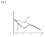
- an opening movement supporting tension spring is provided, which in the range from about 4 to 10 ° door opening angle up to a door opening angle about 70 to 80 °, a sharply decreasing torque curve is achieved.
- the torque curve increases advantageously again, whereby the further wing movement in the opening direction is difficult and thus at least hampers striking the wing, to avoid damage to, for example, a wall.
- the arranged in the slide tension spring is accommodated at one end in a spring holder which is displaceable in the slide rail and, for example by means of a clamping screw, can be fixed.
- a driver is arranged on the tension spring which, with the slider arranged on the sliding arm, maximally tensions the tension spring when the wing is closed.
- the desired maximum tensile stress is adjustable by the relaxed state of the tension spring of the spring holder is adjusted relative to the position of the slider with the wing closed.
- a positionable stop for the driver can be advantageously provided in the slide, whereby the opening support is terminated by the tension spring at a desired opening angle. The driver arrives at the opening movement the stop, whereby the slider is released from the driver and the wing can be further opened against the force of the arranged in the drive housing compression spring.
- the tension spring can also be formed as a spring pack with a plurality of springs juxtaposed springs smaller diameter to obtain small dimensions of the slide rail.
- other elastic elements such as a rubber cord can be used.
- the area of the opening assistance can be selected.
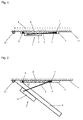
- FIG. 1 is a view from above of a door with a drive 1 shown.
- the drive housing 2 of the drive 1 is arranged in the illustrated embodiment on a pivotally mounted in hinges 10 wings 9 of the door.
- a sliding arm is on an output shaft of the drive 1 5 arranged rotationally fixed.
- a pivoting of the sliding arm 5 from the starting position, which corresponds to the closed position of the wing 9, by opening the wing 9 causes via the output shaft in the drive housing 2 a sliding movement, for example, a arranged in the drive housing 2 piston against a compression spring.
- the energy stored by the compression of the compression spring is again available for closing the wing 9, wherein the sliding arm 5 is acted upon by the output shaft for the closing operation.
- the sliding arm 5 is guided by means of a slider 4 in a slide rail 3, which on a frame 11, which is merely indicated in the figure.
- a tension spring 6 is arranged next to the slider 4, which is held at one end in a spring holder 8 which is adjustably adjustable in the slide rail 3 for adjusting the spring tension.
- a driver 7 is arranged on the tension spring 6, which cooperates with the slider 4. In the closed position of the wing 9, the slider 4 is in contact with the driver 7, whereby the driver 7 by the slider 4 in the Fig. 1 moved to the right and the tension spring 6 is stretched.
- the support of the opening movement of the wing 6 by reducing the opening torque against the force of the arranged in the drive housing 2 compression spring can due to the geometric conditions, such as the position of the articulation points of the sliding arm 5 on the output shaft and the slider 4 to each other and the length of the sliding arm 5, up to a door opening angle of about 70 to 80 ° facilitate the opening of the wing 9.
- an increase in the moment is desired again, for example, to prevent a striking of the wing 9 on a wall and to provide a sufficient closing force.
Landscapes
- Power-Operated Mechanisms For Wings (AREA)
- Closing And Opening Devices For Wings, And Checks For Wings (AREA)
Abstract
Description
- Die Erfindung betrifft einen Antrieb für einen Flügel einer Tür oder eines Fensters nach Patentanspruch 1.
- Aus der
DE 196 41 799 A1 ist ein Antrieb für einen Flügel einer Tür oder eines Fensters bekannt, mit einem in einer Gleitschiene verschiebbar geführten Gleitarm, welcher mit einer Abtriebswelle des Antriebs verbunden ist. Zur Verbesserung des Momentenverlaufs ist die Führungsbahn in der Gleitschiene nicht parallel zur Ebene des Flügels bzw. des Türrahmens, sondern kurvenförmig ausgebildet. - Nachteilig benötigt die Gleitschiene eine größere Bautiefe zur Anordnung der kurvenförmigen Führungsbahn der Gleitschiene. Weiterhin erhöht sich die zu Beginn der Türöffnung erforderliche Kraft.
- Der Erfindung liegt die Aufgabe zugrunde, einen gattungsgemäßen Antrieb dahingehend zu verbessern, dass sich die Kraft zur Türöffnung zu Beginn der Öffnungsbewegung des Flügels verringert.
- Die Aufgabe wird durch die Merkmale des Patentanspruchs 1 gelöst.
- Die Unteransprüche bilden vorteilhafte Ausgestaltungsmöglichkeiten der Erfindung.
- Gattungsgemäße Antriebe für Flügel von Türen oder Fenstern sind an sich allgemein bekannt. In einem Antriebsgehäuse ist ein gegen eine Feder verschiebbarer Kolben angeordnet, welcher eine Verzahnung aufweist, in der ein Ritzel einer Abtriebswelle kämmt. Auf der Abtriebswelle ist ein Gleitarm drehfest angeordnet, der andernends mit einem Gleiter in einer Gleitschiene geführt ist. Das Antriebsgehäuse kann auf dem Flügel der Tür oder des Fensters angeordnet sein und die Gleitschiene an dem den Flügel umgebenden Rahmen. In alternativer Ausgestaltung kann das Antriebsgehäuse auch auf den Rahmen und die Gleitschiene auf dem Flügel angeordnet sein. Der Flügel muss gegen die Kraft der im Antriebsgehäuse angeordneten Feder geöffnet werden, wobei durch die Hebelverhältnisse zu Beginn der Öffnungsbewegung ein hohes Moment erforderlich ist, um den Flügel zu öffnen.
- Zur Verbesserung des Momentenverlaufs an dem Flügel der Tür oder des Fensters ist eine die Öffnungsbewegung unterstützende Zugfeder vorgesehen, wodurch im Bereich ab ca. 4 bis 10° Türöffnungswinkel bis hin zu einem Türöffnungswinkel ca. 70 bis 80°ein stark abfallender Momentenverlauf erzielt wird. Im sich anschließenden Türöffnungsbereich größer als ca. 70 bis 80° steigt der Momentenverlauf vorteilhaft wieder an, wodurch die weitere Flügelbewegung in Öffnungsrichtung erschwert wird und so ein Anschlagen des Flügels, zur Vermeidung von Beschädigungen an beispielsweise einer Wand, zumindest dämpft.
- Die in der Gleitschiene angeordnete Zugfeder ist einerends in einem Federhalter aufgenommen, der in der Gleitschiene verschiebbar und, beispielsweise mittels einer Klemmschraube, festlegbar ist. Andernends ist an der Zugfeder ein Mitnehmer angeordnet, welcher mit dem am Gleitarm angeordneten Gleiter die Zugfeder maximal spannt, wenn der Flügel geschlossen ist. Die gewünschte maximale Zugspannung ist einstellbar, indem in entspanntem Zustand der Zugfeder der Federhalter relativ zur Position des Gleiters bei geschlossenem Flügel verstellt wird.
- Beim Öffnen des Flügels wirkt die Federkraft solange auf den Gleiter ein, bis die Feder vollständig entspannt ist. Da dabei der Gleiter nur in Anlage mit dem Mitnehmer ist, entfernt sich bei weiterem Türöffnen der Gleiter vom Mitnehmer, wobei keine Unterstützung der Öffnungsbewegung durch die Kraft der Zugfeder mehr erfolgt. In einer alternativen Ausgestaltung kann in der Gleitschiene vorteilhaft auch ein positionierbarer Anschlag für den Mitnehmer vorgesehen sein, wodurch die Öffnungsunterstützung durch die Zugfeder bei einem gewünschten Öffnungswinkel beendet wird. Der Mitnehmer gelangt bei der Öffnungsbewegung an den Anschlag, wodurch der Gleiter sich vom Mitnehmer löst und der Flügel gegen die Kraft der im Antriebsgehäuse angeordneten Druckfeder weiter geöffnet werden kann.
- Die Zugfeder kann auch als Federpacket mit mehreren Federn nebeneinander angeordneten Federn kleineren Durchmessers gebildet sein, um geringe Abmessungen der Gleitschiene zu erhalten. Alternativ können auch andere elastische Elemente, wie beispielsweise ein Gummiseil verwendet werden.
- Vorteilhaft kann durch die Einstellung der Spannung der Zugfeder die Ausprägung der Öffnungsunterstützung und durch die Positionierung des Anschlags der Bereich der Öffnungsunterstützung gewählt werden.
- Im Nachfolgenden werden Ausführungsbeispiele in der Zeichnung anhand der Figuren näher erläutert.
- Dabei zeigen:
- Fig. 1
- eine Ansicht von oben auf eine Tür mit einem Antrieb und einer Gleitschiene, wobei die Gleitschiene geschnitten dargestellt ist;
- Fig. 2
- eine Ansicht gemäß
Fig. 1 , wobei sich der Flügel in einer teilweise geöffneten Stellung befindet; - Fig. 3
- eine Ansicht gemäß
Fig. 2 , wobei der Flügel weiter geöffnet ist und in weiterer Ausgestaltung ein Anschlag in der Gleitschiene vorgesehen ist; - Fig. 4
- eine Seitenansicht der Gleitschiene gemäß
Fig. 3 im Schnitt, jedoch in Geschlossenstellung des Flügels; - Fig. 5
- ein Diagramm des Drehmomentverlaufs mit und ohne Zugfederunterstützung in Abhängigkeit des Türöffnungswinkels.
- In der
Fig. 1 ist eine Ansicht von oben auf eine Tür mit einem Antrieb 1 gezeigt. Das Antriebsgehäuse 2 des Antriebs 1 ist im dargestellten Ausführungsbeispiel auf einem schwenkbar in Scharnieren 10 gelagerter Flügel 9 der Tür angeordnet. In an sich bekannter Weise ist auf einer Abtriebswelle des Antriebs 1 ein Gleitarm 5 drehfest angeordnet. Ein Verschwenken des Gleitarms 5 aus der Ausgangsstellung, welche der Geschlossenstellung des Flügels 9 entspricht, durch Öffnen des Flügels 9 bewirkt über die Abtriebswelle im Antriebsgehäuse 2 eine Verschiebebewegung beispielsweise eines in dem Antriebsgehäuse 2 angeordneten Kolbens gegen eine Druckfeder. Die durch die Kompression der Druckfeder gespeicherte Energie steht zum Schließen des Flügels 9 wieder zur Verfügung, wobei für den Schließvorgang der Gleitarm 5 durch die Abtriebswelle beaufschlagt ist. - Der Gleitarm 5 ist mittels eines Gleiters 4 in einer Gleitschiene 3, welche an einem Rahmen 11, welcher in der Figur lediglich angedeutet ist, geführt. In der Gleitschiene 3 ist neben dem Gleiter 4 eine Zugfeder 6 angeordnet, die einerends in einem Federhalter 8, der zur Einstellung der Federspannung verstellbar in der Gleitschiene 3 festlegbar ist, gehalten ist. Durch Verstellen des Federhalters 8 ist es auch möglich die Öffnungsunterstützung vollständig zu deaktivieren. Andernends ist an der Zugfeder 6 ein Mitnehmer 7 angeordnet, welcher mit dem Gleiter 4 zusammenwirkt. In der in Geschlossenstellung des Flügels 9 ist der Gleiter 4 in Anlage mit dem Mitnehmer 7, wodurch der Mitnehmer 7 durch den Gleiter 4 in der
Fig. 1 nach rechts verschoben und die Zugfeder 6 gespannt ist. - Ausgehend von dieser in
Fig. 1 dargestellten Geschlossenlage des Flügels 9 wirkt beim Öffnen des Flügels 9 die Kraft der Zugfeder 6 auf den Gleiter 4 öffnungsunterstützend ein. Bei den zunächst sehr kleinen Türöffnungswinkelnabis ca. 4° ist die Krafteinwirkung aufgrund des kleinen Winkels zwischen der Zugrichtung der Zugfeder 6 und des Gleitarms 5 gering gegenüber der Kraftwirkung der im Antriebsgehäuse 2 des Antriebs 1 angeordneten Druckfeder. Diese geringe Kraftwirkung bei kleinen Türöffnungswinkelnabegünstigt jedoch beim Schließen vorteilhaft die Schließbewegung des Flügels 9, so dass genügend Kraftwirkung durch die Druckfeder im Antriebsgehäuse 2 zur Verfügung steht, um die Schlossfalle zurückzudrücken und den Flügel 9 sicher zu schließen. - Bei größeren Türöffnungswinkelnaab 4° wird die Kraftwirkung der Zugfeder 6 zur Öffnungsunterstützung immer deutlicher durch ein abnehmendes Moment am Flügel 9 bemerkbar, was auch in dem Diagramm in
Fig. 5 , Momentenverlauf 14, gezeigt ist. Im Diagramm ist das Moment am Flügel 9 in Nm über dem sogenannten Türöffnungswinkelα, d.h. dem Öffnungswinkel des Flügels 9 der Tür, dargestellt, wobei der Momentenverlauf 13 den eines Antriebs 1 ohne eine öffnungsunterstützende Zugfeder 6 in der Gleitschiene 3 zeigt. Der Momentenverlauf 14 zeigt den vorteilhaften Verlauf des Moments des Antriebs 1 mit Unterstützung durch die in der Gleitschiene 3 angeordneten Zugfeder 6. - Die Unterstützung der Öffnungsbewegung des Flügels 6 durch Verringerung des Öffnungsmoment gegen die Kraft der im Antriebsgehäuse 2 angeordneten Druckfeder kann aufgrund der geometrischen Gegebenheiten, wie etwa der Lage der Anlenkpunkte des Gleitarms 5 an der Abtriebswelle und am Gleiter 4 zueinander sowie der Länge des Gleitarms 5, bis zu einem Türöffnungswinkel von ca. 70 bis 80°das Öffnen des Flügels 9 erleichtern. Darüber hinaus ist ein Anstieg des Moments wieder erwünscht, um beispielsweise ein Anschlagen des Flügels 9 an einer Wand zu verhindern und um eine ausreichende Schließkraft zur Verfügung zu stellen. Dazu kann die Unterstützung durch die Zugfeder 6 auch ab einem Türöffnungswinkelαvon ca. 80 bis 90° gänzlich verhindert werden, indem der Mitnehmer 7 in Anlage mit einem Anschlag 12 gelangt und so bei einer weiteren Öffnungsbewegung des Flügels 6 nicht mehr in Anlage mit dem Gleiter 4 ist, wie es in der
Fig. 3 gezeigt ist. -
- 1
- Antrieb
- 2
- Antriebsgehäuse
- 3
- Gleitschiene
- 4
- Gleiter
- 5
- Gleitarm
- 6
- Zugfeder
- 7
- Mitnehmer
- 8
- Federhalter
- 9
- Flügel
- 10
- Scharnier
- 11
- Rahmen
- 12
- Anschlag
- 13
- Drehmomentverlauf ohne Zugfederunterstützung
- 14
- Drehmomentverlauf mit Zugfederunterstützung
- α
- Türöffnungswinkel
Claims (6)
- Antrieb (1) für einen Flügel (9) einer Tür oder eines Fensters, mit einem Antriebsgehäuse (2), und mit einem an einer im Antriebsgehäuse (2) angeordneten Abtriebswelle, mit welcher ein mittels eines Gleiters (4) in einer Gleitschiene (3) geführter Gleitarm (5) drehfest verbunden ist,
dadurch gekennzeichnet,
dass in der Gleitschiene (3) eine Zugfeder (6) angeordnet ist, und dass der Gleiter (4) in Geschlossenstellung des Flügels (9) an einem Mitnehmer (7) der Zugfeder (6) anliegt und die Zugfeder (6) spannt. - Antrieb nach Anspruch 1,
dadurch gekennzeichnet, dass sich der Gleiter (4) bei der Öffnungsbewegung ab einem Bereich eines Türöffnungswinkels (α) von etwa 70° bis 80° vom Mitnehmer (7) löst. - Antrieb nach Anspruch 1 oder 2,
dadurch gekennzeichnet, dass ein Anschlag (12) vorgesehen ist, mit welchem der Mitnehmer (7) beim Öffnen des Flügels (9) in Anlage gelangt, wobei sich der Gleiter (4) bei weiterem Öffnen des Flügels (9) vom Mitnehmer (7) entfernt. - Antrieb nach Anspruch 1,
dadurch gekennzeichnet, dass ein Ende der Zugfeder (6) in einem Federhalter (8) aufgenommen ist. - Antrieb nach Anspruch 4,
dadurch gekennzeichnet, dass der Federhalter (8) in der Gleitschiene (3) zur Einstellung der Federspannung der Zugfeder (6) verstellbar und festlegbar ist. - Antrieb nach Anspruch 3,
dadurch gekennzeichnet, dass der Anschlag (12) in der Gleitschiene (3) zur Festlegung des Wirkungsbereichs der Öffnungsunterstützung durch die Zugfeder (6) verstellbar und festlegbar ist.
Priority Applications (2)
| Application Number | Priority Date | Filing Date | Title |
|---|---|---|---|
| EP10190482.9A EP2450514B1 (de) | 2010-11-09 | 2010-11-09 | Antrieb für einen Flügel einer Tür oder eines Fensters |
| ES10190482.9T ES2469891T3 (es) | 2010-11-09 | 2010-11-09 | Accionamiento para una hoja de una puerta o una ventana |
Applications Claiming Priority (1)
| Application Number | Priority Date | Filing Date | Title |
|---|---|---|---|
| EP10190482.9A EP2450514B1 (de) | 2010-11-09 | 2010-11-09 | Antrieb für einen Flügel einer Tür oder eines Fensters |
Publications (2)
| Publication Number | Publication Date |
|---|---|
| EP2450514A1 true EP2450514A1 (de) | 2012-05-09 |
| EP2450514B1 EP2450514B1 (de) | 2014-04-23 |
Family
ID=43838229
Family Applications (1)
| Application Number | Title | Priority Date | Filing Date |
|---|---|---|---|
| EP10190482.9A Active EP2450514B1 (de) | 2010-11-09 | 2010-11-09 | Antrieb für einen Flügel einer Tür oder eines Fensters |
Country Status (2)
| Country | Link |
|---|---|
| EP (1) | EP2450514B1 (de) |
| ES (1) | ES2469891T3 (de) |
Cited By (2)
| Publication number | Priority date | Publication date | Assignee | Title |
|---|---|---|---|---|
| CN108915462A (zh) * | 2018-05-21 | 2018-11-30 | 河北卓达建材研究院有限公司 | 一种门阻装置 |
| EP3626922A1 (de) * | 2018-09-19 | 2020-03-25 | dormakaba Deutschland GmbH | Betätigungshilfe, system aus einem drehlager und mindestens einer betätigungshilfe sowie verfahren zum unterstützen einer manuellen türbetätigung mit einer hilfskraft durch mindestens eine betätigungshilfe |
Families Citing this family (1)
| Publication number | Priority date | Publication date | Assignee | Title |
|---|---|---|---|---|
| NL2037923B1 (en) * | 2024-06-11 | 2026-01-08 | Interdam Holding B V | An escape door unit and a door opening assistant |
Citations (4)
| Publication number | Priority date | Publication date | Assignee | Title |
|---|---|---|---|---|
| GB191201283A (en) * | 1912-01-16 | 1912-07-11 | Timothy Kelly | Improved Door Closing Appliance. |
| DE19641799A1 (de) | 1996-10-10 | 1998-04-16 | Geze Gmbh & Co | Antrieb zum Öffnen und/oder Schließen eines Flügels, einer Tür, eines Fensters o. dgl. |
| DE10001950A1 (de) * | 1999-01-18 | 2000-07-20 | Geze Gmbh | Antrieb |
| DE10001424A1 (de) * | 1999-01-16 | 2000-07-20 | Geze Gmbh | Tür mit drehbar in Türbändern gelagerte Türflügel |
-
2010
- 2010-11-09 ES ES10190482.9T patent/ES2469891T3/es active Active
- 2010-11-09 EP EP10190482.9A patent/EP2450514B1/de active Active
Patent Citations (4)
| Publication number | Priority date | Publication date | Assignee | Title |
|---|---|---|---|---|
| GB191201283A (en) * | 1912-01-16 | 1912-07-11 | Timothy Kelly | Improved Door Closing Appliance. |
| DE19641799A1 (de) | 1996-10-10 | 1998-04-16 | Geze Gmbh & Co | Antrieb zum Öffnen und/oder Schließen eines Flügels, einer Tür, eines Fensters o. dgl. |
| DE10001424A1 (de) * | 1999-01-16 | 2000-07-20 | Geze Gmbh | Tür mit drehbar in Türbändern gelagerte Türflügel |
| DE10001950A1 (de) * | 1999-01-18 | 2000-07-20 | Geze Gmbh | Antrieb |
Cited By (2)
| Publication number | Priority date | Publication date | Assignee | Title |
|---|---|---|---|---|
| CN108915462A (zh) * | 2018-05-21 | 2018-11-30 | 河北卓达建材研究院有限公司 | 一种门阻装置 |
| EP3626922A1 (de) * | 2018-09-19 | 2020-03-25 | dormakaba Deutschland GmbH | Betätigungshilfe, system aus einem drehlager und mindestens einer betätigungshilfe sowie verfahren zum unterstützen einer manuellen türbetätigung mit einer hilfskraft durch mindestens eine betätigungshilfe |
Also Published As
| Publication number | Publication date |
|---|---|
| ES2469891T3 (es) | 2014-06-20 |
| EP2450514B1 (de) | 2014-04-23 |
Similar Documents
| Publication | Publication Date | Title |
|---|---|---|
| DE102011087695B4 (de) | Vorrichtung zur Öffnungsdämpfung eines Flügels einer Tür oder eines Fensters | |
| DE102013001402B4 (de) | Scharnier für einen Herd sowie Herd | |
| DE102011006524B4 (de) | Tür oder Fenster eines Gebäudes mit einer motorischen Antriebsvorrichtung | |
| AT515216A4 (de) | Stellantrieb für Möbelklappen | |
| EP2191089A1 (de) | Stellmechanismus für einen schwenkbar gelagerten stellarm | |
| DE102016104778B4 (de) | Türantrieb mit Haupt- und Hilfsantrieb | |
| DE102009006946B4 (de) | Tür, insbesondere Kraftfahrzeugtür | |
| EP2450514B1 (de) | Antrieb für einen Flügel einer Tür oder eines Fensters | |
| DE102013100293A1 (de) | Türschließerantrieb | |
| EP2900890B1 (de) | Schliessvorrichtung einer gebäudeöffnung | |
| EP2540616B1 (de) | Schließmechanismus für eine mit Kraftunterstützung schließende Schiebetüre | |
| EP2363310B1 (de) | Kraftfahrzeug mit schwenkbar gelagerter Fahrzeugtür mit rahmenloser Fensterscheibe | |
| DE102015100547A1 (de) | Ausstellvorrichtung für ein Fenster oder eine Tür mit einer Energiespeichereinrichtung | |
| EP2620575A2 (de) | Öffnungsunterstützungsvorrichtung für ein Fenster, eine Tür oder dergleichen sowie ein entsprechendes Fenster | |
| EP3688260B1 (de) | In der kippstellung verrastbarer und dennoch beim schieb-schliessen leicht bewegbarer beschlag für ein fenster oder eine tür | |
| DE102013205206B4 (de) | Einzugsvorrichtung für einen Flügel einer Tür oder eines Fensters | |
| DE102011016729B4 (de) | Vorrichtung zum fremdkraftunterstützten Verschwenken einer Klappe oder Tür und Fahrzeug | |
| EP3260638A1 (de) | Faltladenvorrichtung zum abdecken einer fassade | |
| EP1544395B1 (de) | Vorrichtung zur Schliessfolgeregelung für zweiflügelige Drehtüren | |
| EP2647786B1 (de) | Antrieb für einen flügel eines fensters oder dergleichen | |
| DE102012102026A1 (de) | Gleitschienenanordnung | |
| EP1965010A1 (de) | Antriebsvorrichtung | |
| DE19831783A1 (de) | Türschließer mit automatischer Schließbewegung und Kraftspeicher in der Führungsschiene | |
| DE202010010494U1 (de) | Rauchabzugsvorrichtung | |
| DE102012213782A1 (de) | Verlagerungsanordnung zur Verlagerung eines Schiebeflügels eines Fensters, einer Tür oder dergleichen relativ zu einer festen Einfassung mit einem flügelseitigen und einem einfassungsseitigen Steuerelement |
Legal Events
| Date | Code | Title | Description |
|---|---|---|---|
| PUAI | Public reference made under article 153(3) epc to a published international application that has entered the european phase |
Free format text: ORIGINAL CODE: 0009012 |
|
| AK | Designated contracting states |
Kind code of ref document: A1 Designated state(s): AL AT BE BG CH CY CZ DE DK EE ES FI FR GB GR HR HU IE IS IT LI LT LU LV MC MK MT NL NO PL PT RO RS SE SI SK SM TR |
|
| AX | Request for extension of the european patent |
Extension state: BA ME |
|
| 17P | Request for examination filed |
Effective date: 20121016 |
|
| GRAP | Despatch of communication of intention to grant a patent |
Free format text: ORIGINAL CODE: EPIDOSNIGR1 |
|
| RIC1 | Information provided on ipc code assigned before grant |
Ipc: E05F 1/10 20060101ALI20131219BHEP Ipc: E05F 3/10 20060101AFI20131219BHEP |
|
| INTG | Intention to grant announced |
Effective date: 20140120 |
|
| GRAS | Grant fee paid |
Free format text: ORIGINAL CODE: EPIDOSNIGR3 |
|
| GRAA | (expected) grant |
Free format text: ORIGINAL CODE: 0009210 |
|
| AK | Designated contracting states |
Kind code of ref document: B1 Designated state(s): AL AT BE BG CH CY CZ DE DK EE ES FI FR GB GR HR HU IE IS IT LI LT LU LV MC MK MT NL NO PL PT RO RS SE SI SK SM TR |
|
| REG | Reference to a national code |
Ref country code: GB Ref legal event code: FG4D Free format text: NOT ENGLISH |
|
| REG | Reference to a national code |
Ref country code: CH Ref legal event code: EP |
|
| REG | Reference to a national code |
Ref country code: AT Ref legal event code: REF Ref document number: 663984 Country of ref document: AT Kind code of ref document: T Effective date: 20140515 |
|
| REG | Reference to a national code |
Ref country code: IE Ref legal event code: FG4D Free format text: LANGUAGE OF EP DOCUMENT: GERMAN |
|
| REG | Reference to a national code |
Ref country code: DE Ref legal event code: R096 Ref document number: 502010006731 Country of ref document: DE Effective date: 20140528 |
|
| REG | Reference to a national code |
Ref country code: ES Ref legal event code: FG2A Ref document number: 2469891 Country of ref document: ES Kind code of ref document: T3 Effective date: 20140620 |
|
| REG | Reference to a national code |
Ref country code: NL Ref legal event code: VDEP Effective date: 20140423 |
|
| REG | Reference to a national code |
Ref country code: LT Ref legal event code: MG4D |
|
| PG25 | Lapsed in a contracting state [announced via postgrant information from national office to epo] |
Ref country code: CY Free format text: LAPSE BECAUSE OF FAILURE TO SUBMIT A TRANSLATION OF THE DESCRIPTION OR TO PAY THE FEE WITHIN THE PRESCRIBED TIME-LIMIT Effective date: 20140423 Ref country code: BG Free format text: LAPSE BECAUSE OF FAILURE TO SUBMIT A TRANSLATION OF THE DESCRIPTION OR TO PAY THE FEE WITHIN THE PRESCRIBED TIME-LIMIT Effective date: 20140723 Ref country code: NO Free format text: LAPSE BECAUSE OF FAILURE TO SUBMIT A TRANSLATION OF THE DESCRIPTION OR TO PAY THE FEE WITHIN THE PRESCRIBED TIME-LIMIT Effective date: 20140723 Ref country code: LT Free format text: LAPSE BECAUSE OF FAILURE TO SUBMIT A TRANSLATION OF THE DESCRIPTION OR TO PAY THE FEE WITHIN THE PRESCRIBED TIME-LIMIT Effective date: 20140423 Ref country code: GR Free format text: LAPSE BECAUSE OF FAILURE TO SUBMIT A TRANSLATION OF THE DESCRIPTION OR TO PAY THE FEE WITHIN THE PRESCRIBED TIME-LIMIT Effective date: 20140724 Ref country code: FI Free format text: LAPSE BECAUSE OF FAILURE TO SUBMIT A TRANSLATION OF THE DESCRIPTION OR TO PAY THE FEE WITHIN THE PRESCRIBED TIME-LIMIT Effective date: 20140423 Ref country code: IS Free format text: LAPSE BECAUSE OF FAILURE TO SUBMIT A TRANSLATION OF THE DESCRIPTION OR TO PAY THE FEE WITHIN THE PRESCRIBED TIME-LIMIT Effective date: 20140823 Ref country code: NL Free format text: LAPSE BECAUSE OF FAILURE TO SUBMIT A TRANSLATION OF THE DESCRIPTION OR TO PAY THE FEE WITHIN THE PRESCRIBED TIME-LIMIT Effective date: 20140423 |
|
| PG25 | Lapsed in a contracting state [announced via postgrant information from national office to epo] |
Ref country code: RS Free format text: LAPSE BECAUSE OF FAILURE TO SUBMIT A TRANSLATION OF THE DESCRIPTION OR TO PAY THE FEE WITHIN THE PRESCRIBED TIME-LIMIT Effective date: 20140423 Ref country code: HR Free format text: LAPSE BECAUSE OF FAILURE TO SUBMIT A TRANSLATION OF THE DESCRIPTION OR TO PAY THE FEE WITHIN THE PRESCRIBED TIME-LIMIT Effective date: 20140423 Ref country code: PL Free format text: LAPSE BECAUSE OF FAILURE TO SUBMIT A TRANSLATION OF THE DESCRIPTION OR TO PAY THE FEE WITHIN THE PRESCRIBED TIME-LIMIT Effective date: 20140423 Ref country code: SE Free format text: LAPSE BECAUSE OF FAILURE TO SUBMIT A TRANSLATION OF THE DESCRIPTION OR TO PAY THE FEE WITHIN THE PRESCRIBED TIME-LIMIT Effective date: 20140423 Ref country code: LV Free format text: LAPSE BECAUSE OF FAILURE TO SUBMIT A TRANSLATION OF THE DESCRIPTION OR TO PAY THE FEE WITHIN THE PRESCRIBED TIME-LIMIT Effective date: 20140423 |
|
| PG25 | Lapsed in a contracting state [announced via postgrant information from national office to epo] |
Ref country code: PT Free format text: LAPSE BECAUSE OF FAILURE TO SUBMIT A TRANSLATION OF THE DESCRIPTION OR TO PAY THE FEE WITHIN THE PRESCRIBED TIME-LIMIT Effective date: 20140825 |
|
| REG | Reference to a national code |
Ref country code: DE Ref legal event code: R097 Ref document number: 502010006731 Country of ref document: DE |
|
| PG25 | Lapsed in a contracting state [announced via postgrant information from national office to epo] |
Ref country code: CZ Free format text: LAPSE BECAUSE OF FAILURE TO SUBMIT A TRANSLATION OF THE DESCRIPTION OR TO PAY THE FEE WITHIN THE PRESCRIBED TIME-LIMIT Effective date: 20140423 Ref country code: RO Free format text: LAPSE BECAUSE OF FAILURE TO SUBMIT A TRANSLATION OF THE DESCRIPTION OR TO PAY THE FEE WITHIN THE PRESCRIBED TIME-LIMIT Effective date: 20140423 Ref country code: SK Free format text: LAPSE BECAUSE OF FAILURE TO SUBMIT A TRANSLATION OF THE DESCRIPTION OR TO PAY THE FEE WITHIN THE PRESCRIBED TIME-LIMIT Effective date: 20140423 Ref country code: EE Free format text: LAPSE BECAUSE OF FAILURE TO SUBMIT A TRANSLATION OF THE DESCRIPTION OR TO PAY THE FEE WITHIN THE PRESCRIBED TIME-LIMIT Effective date: 20140423 Ref country code: DK Free format text: LAPSE BECAUSE OF FAILURE TO SUBMIT A TRANSLATION OF THE DESCRIPTION OR TO PAY THE FEE WITHIN THE PRESCRIBED TIME-LIMIT Effective date: 20140423 |
|
| PLBE | No opposition filed within time limit |
Free format text: ORIGINAL CODE: 0009261 |
|
| STAA | Information on the status of an ep patent application or granted ep patent |
Free format text: STATUS: NO OPPOSITION FILED WITHIN TIME LIMIT |
|
| PG25 | Lapsed in a contracting state [announced via postgrant information from national office to epo] |
Ref country code: IT Free format text: LAPSE BECAUSE OF FAILURE TO SUBMIT A TRANSLATION OF THE DESCRIPTION OR TO PAY THE FEE WITHIN THE PRESCRIBED TIME-LIMIT Effective date: 20140423 |
|
| 26N | No opposition filed |
Effective date: 20150126 |
|
| REG | Reference to a national code |
Ref country code: DE Ref legal event code: R097 Ref document number: 502010006731 Country of ref document: DE Effective date: 20150126 |
|
| PG25 | Lapsed in a contracting state [announced via postgrant information from national office to epo] |
Ref country code: MC Free format text: LAPSE BECAUSE OF FAILURE TO SUBMIT A TRANSLATION OF THE DESCRIPTION OR TO PAY THE FEE WITHIN THE PRESCRIBED TIME-LIMIT Effective date: 20140423 Ref country code: BE Free format text: LAPSE BECAUSE OF NON-PAYMENT OF DUE FEES Effective date: 20141130 Ref country code: LU Free format text: LAPSE BECAUSE OF FAILURE TO SUBMIT A TRANSLATION OF THE DESCRIPTION OR TO PAY THE FEE WITHIN THE PRESCRIBED TIME-LIMIT Effective date: 20141109 |
|
| PG25 | Lapsed in a contracting state [announced via postgrant information from national office to epo] |
Ref country code: SI Free format text: LAPSE BECAUSE OF FAILURE TO SUBMIT A TRANSLATION OF THE DESCRIPTION OR TO PAY THE FEE WITHIN THE PRESCRIBED TIME-LIMIT Effective date: 20140423 |
|
| REG | Reference to a national code |
Ref country code: IE Ref legal event code: MM4A |
|
| PG25 | Lapsed in a contracting state [announced via postgrant information from national office to epo] |
Ref country code: IE Free format text: LAPSE BECAUSE OF NON-PAYMENT OF DUE FEES Effective date: 20141109 |
|
| REG | Reference to a national code |
Ref country code: FR Ref legal event code: PLFP Year of fee payment: 6 |
|
| PG25 | Lapsed in a contracting state [announced via postgrant information from national office to epo] |
Ref country code: SM Free format text: LAPSE BECAUSE OF FAILURE TO SUBMIT A TRANSLATION OF THE DESCRIPTION OR TO PAY THE FEE WITHIN THE PRESCRIBED TIME-LIMIT Effective date: 20140423 |
|
| PG25 | Lapsed in a contracting state [announced via postgrant information from national office to epo] |
Ref country code: TR Free format text: LAPSE BECAUSE OF FAILURE TO SUBMIT A TRANSLATION OF THE DESCRIPTION OR TO PAY THE FEE WITHIN THE PRESCRIBED TIME-LIMIT Effective date: 20140423 Ref country code: HU Free format text: LAPSE BECAUSE OF FAILURE TO SUBMIT A TRANSLATION OF THE DESCRIPTION OR TO PAY THE FEE WITHIN THE PRESCRIBED TIME-LIMIT; INVALID AB INITIO Effective date: 20101109 Ref country code: MT Free format text: LAPSE BECAUSE OF FAILURE TO SUBMIT A TRANSLATION OF THE DESCRIPTION OR TO PAY THE FEE WITHIN THE PRESCRIBED TIME-LIMIT Effective date: 20140423 |
|
| REG | Reference to a national code |
Ref country code: FR Ref legal event code: PLFP Year of fee payment: 7 |
|
| REG | Reference to a national code |
Ref country code: FR Ref legal event code: PLFP Year of fee payment: 8 |
|
| PG25 | Lapsed in a contracting state [announced via postgrant information from national office to epo] |
Ref country code: MK Free format text: LAPSE BECAUSE OF FAILURE TO SUBMIT A TRANSLATION OF THE DESCRIPTION OR TO PAY THE FEE WITHIN THE PRESCRIBED TIME-LIMIT Effective date: 20140423 |
|
| PG25 | Lapsed in a contracting state [announced via postgrant information from national office to epo] |
Ref country code: AL Free format text: LAPSE BECAUSE OF FAILURE TO SUBMIT A TRANSLATION OF THE DESCRIPTION OR TO PAY THE FEE WITHIN THE PRESCRIBED TIME-LIMIT Effective date: 20140423 |
|
| P01 | Opt-out of the competence of the unified patent court (upc) registered |
Effective date: 20230510 |
|
| REG | Reference to a national code |
Ref country code: CH Ref legal event code: U11 Free format text: ST27 STATUS EVENT CODE: U-0-0-U10-U11 (AS PROVIDED BY THE NATIONAL OFFICE) Effective date: 20251201 |
|
| PGFP | Annual fee paid to national office [announced via postgrant information from national office to epo] |
Ref country code: DE Payment date: 20251130 Year of fee payment: 16 |
|
| PGFP | Annual fee paid to national office [announced via postgrant information from national office to epo] |
Ref country code: GB Payment date: 20251121 Year of fee payment: 16 |
|
| PGFP | Annual fee paid to national office [announced via postgrant information from national office to epo] |
Ref country code: AT Payment date: 20251120 Year of fee payment: 16 |
|
| PGFP | Annual fee paid to national office [announced via postgrant information from national office to epo] |
Ref country code: FR Payment date: 20251124 Year of fee payment: 16 |
|
| PGFP | Annual fee paid to national office [announced via postgrant information from national office to epo] |
Ref country code: CH Payment date: 20251201 Year of fee payment: 16 |
|
| PGFP | Annual fee paid to national office [announced via postgrant information from national office to epo] |
Ref country code: ES Payment date: 20251229 Year of fee payment: 16 |