EP2449971A2 - Verschlusseinrichtung eines Septumschadens - Google Patents
Verschlusseinrichtung eines Septumschadens Download PDFInfo
- Publication number
- EP2449971A2 EP2449971A2 EP10015699A EP10015699A EP2449971A2 EP 2449971 A2 EP2449971 A2 EP 2449971A2 EP 10015699 A EP10015699 A EP 10015699A EP 10015699 A EP10015699 A EP 10015699A EP 2449971 A2 EP2449971 A2 EP 2449971A2
- Authority
- EP
- European Patent Office
- Prior art keywords
- skeleton
- coil
- skeletons
- disc
- metal mesh
- Prior art date
- Legal status (The legal status is an assumption and is not a legal conclusion. Google has not performed a legal analysis and makes no representation as to the accuracy of the status listed.)
- Granted
Links
- 208000025339 heart septal defect Diseases 0.000 title claims description 7
- 239000012528 membrane Substances 0.000 claims abstract description 27
- 229910052751 metal Inorganic materials 0.000 claims abstract description 20
- 239000002184 metal Substances 0.000 claims abstract description 19
- 229920000295 expanded polytetrafluoroethylene Polymers 0.000 claims description 3
- HLXZNVUGXRDIFK-UHFFFAOYSA-N nickel titanium Chemical compound [Ti].[Ti].[Ti].[Ti].[Ti].[Ti].[Ti].[Ti].[Ti].[Ti].[Ti].[Ni].[Ni].[Ni].[Ni].[Ni].[Ni].[Ni].[Ni].[Ni].[Ni].[Ni].[Ni].[Ni].[Ni] HLXZNVUGXRDIFK-UHFFFAOYSA-N 0.000 claims description 3
- 229910001000 nickel titanium Inorganic materials 0.000 claims description 3
- NRTOMJZYCJJWKI-UHFFFAOYSA-N Titanium nitride Chemical compound [Ti]#N NRTOMJZYCJJWKI-UHFFFAOYSA-N 0.000 claims description 2
- 239000000463 material Substances 0.000 claims description 2
- 239000010409 thin film Substances 0.000 claims description 2
- 238000004804 winding Methods 0.000 claims description 2
- 208000008883 Patent Foramen Ovale Diseases 0.000 description 13
- 208000035478 Interatrial communication Diseases 0.000 description 11
- 208000013914 atrial heart septal defect Diseases 0.000 description 11
- 206010003664 atrial septal defect Diseases 0.000 description 11
- 208000027418 Wounds and injury Diseases 0.000 description 9
- 239000000560 biocompatible material Substances 0.000 description 7
- 208000007536 Thrombosis Diseases 0.000 description 6
- 208000003278 patent ductus arteriosus Diseases 0.000 description 6
- 210000001519 tissue Anatomy 0.000 description 6
- 208000001910 Ventricular Heart Septal Defects Diseases 0.000 description 5
- 210000003484 anatomy Anatomy 0.000 description 5
- 230000006378 damage Effects 0.000 description 5
- 208000014674 injury Diseases 0.000 description 5
- 238000000034 method Methods 0.000 description 5
- 201000003130 ventricular septal defect Diseases 0.000 description 5
- 238000003466 welding Methods 0.000 description 5
- 208000002330 Congenital Heart Defects Diseases 0.000 description 4
- 238000010276 construction Methods 0.000 description 4
- 230000007547 defect Effects 0.000 description 4
- 238000010438 heat treatment Methods 0.000 description 4
- 230000004048 modification Effects 0.000 description 4
- 238000012986 modification Methods 0.000 description 4
- RVTZCBVAJQQJTK-UHFFFAOYSA-N oxygen(2-);zirconium(4+) Chemical compound [O-2].[O-2].[Zr+4] RVTZCBVAJQQJTK-UHFFFAOYSA-N 0.000 description 4
- 230000008901 benefit Effects 0.000 description 3
- 230000006870 function Effects 0.000 description 3
- 210000005246 left atrium Anatomy 0.000 description 3
- 210000005245 right atrium Anatomy 0.000 description 3
- PXHVJJICTQNCMI-UHFFFAOYSA-N Nickel Chemical compound [Ni] PXHVJJICTQNCMI-UHFFFAOYSA-N 0.000 description 2
- 238000005452 bending Methods 0.000 description 2
- 239000008280 blood Substances 0.000 description 2
- 210000004369 blood Anatomy 0.000 description 2
- 208000028831 congenital heart disease Diseases 0.000 description 2
- 230000000694 effects Effects 0.000 description 2
- 210000005003 heart tissue Anatomy 0.000 description 2
- 206010003658 Atrial Fibrillation Diseases 0.000 description 1
- 206010020751 Hypersensitivity Diseases 0.000 description 1
- 208000026935 allergic disease Diseases 0.000 description 1
- 230000007815 allergy Effects 0.000 description 1
- 230000015572 biosynthetic process Effects 0.000 description 1
- 238000005524 ceramic coating Methods 0.000 description 1
- 230000008859 change Effects 0.000 description 1
- 230000008602 contraction Effects 0.000 description 1
- 230000007797 corrosion Effects 0.000 description 1
- 238000005260 corrosion Methods 0.000 description 1
- 239000013078 crystal Substances 0.000 description 1
- 230000003247 decreasing effect Effects 0.000 description 1
- 230000004992 fission Effects 0.000 description 1
- 230000010354 integration Effects 0.000 description 1
- 230000007774 longterm Effects 0.000 description 1
- 238000000465 moulding Methods 0.000 description 1
- 229910052759 nickel Inorganic materials 0.000 description 1
- 230000008569 process Effects 0.000 description 1
- 230000008439 repair process Effects 0.000 description 1
- 230000003763 resistance to breakage Effects 0.000 description 1
- 239000007787 solid Substances 0.000 description 1
- 229910001220 stainless steel Inorganic materials 0.000 description 1
- 230000007704 transition Effects 0.000 description 1
- 238000009941 weaving Methods 0.000 description 1
Images


Classifications
-
- A—HUMAN NECESSITIES
- A61—MEDICAL OR VETERINARY SCIENCE; HYGIENE
- A61B—DIAGNOSIS; SURGERY; IDENTIFICATION
- A61B17/00—Surgical instruments, devices or methods
- A61B17/0057—Implements for plugging an opening in the wall of a hollow or tubular organ, e.g. for sealing a vessel puncture or closing a cardiac septal defect
- A61B2017/00575—Implements for plugging an opening in the wall of a hollow or tubular organ, e.g. for sealing a vessel puncture or closing a cardiac septal defect for closure at remote site, e.g. closing atrial septum defects
- A61B2017/00592—Elastic or resilient implements
-
- A—HUMAN NECESSITIES
- A61—MEDICAL OR VETERINARY SCIENCE; HYGIENE
- A61B—DIAGNOSIS; SURGERY; IDENTIFICATION
- A61B17/00—Surgical instruments, devices or methods
- A61B17/0057—Implements for plugging an opening in the wall of a hollow or tubular organ, e.g. for sealing a vessel puncture or closing a cardiac septal defect
- A61B2017/00575—Implements for plugging an opening in the wall of a hollow or tubular organ, e.g. for sealing a vessel puncture or closing a cardiac septal defect for closure at remote site, e.g. closing atrial septum defects
- A61B2017/00597—Implements comprising a membrane
-
- A—HUMAN NECESSITIES
- A61—MEDICAL OR VETERINARY SCIENCE; HYGIENE
- A61B—DIAGNOSIS; SURGERY; IDENTIFICATION
- A61B17/00—Surgical instruments, devices or methods
- A61B17/0057—Implements for plugging an opening in the wall of a hollow or tubular organ, e.g. for sealing a vessel puncture or closing a cardiac septal defect
- A61B2017/00575—Implements for plugging an opening in the wall of a hollow or tubular organ, e.g. for sealing a vessel puncture or closing a cardiac septal defect for closure at remote site, e.g. closing atrial septum defects
- A61B2017/00615—Implements with an occluder on one side of the opening and holding means therefor on the other
-
- A—HUMAN NECESSITIES
- A61—MEDICAL OR VETERINARY SCIENCE; HYGIENE
- A61B—DIAGNOSIS; SURGERY; IDENTIFICATION
- A61B17/00—Surgical instruments, devices or methods
- A61B2017/00831—Material properties
- A61B2017/00867—Material properties shape memory effect
Definitions
- the present invention relates to an occlusion device for treating congenital heart disease, such as patent foramen ovale (PFO), atrial septal defect (ASD), patent ductus arteriosus (PDA) or ventricular septal defect (VSD), etc.
- PFO patent foramen ovale
- ASD atrial septal defect
- PDA patent ductus arteriosus
- VSD ventricular septal defect
- Congenital heart diseases include patent foramen ovale (PFO), atrial septal defect (ASD), patent ductus arteriosus (PDA) and ventricular septal defect (VSD), etc.
- PFO and ASD are openings in the wall between the right atrium and left atrium of the heart thereby creating the possibility that the blood could pass from the right atrium to the left atrium.
- the defect size of PFO is usually smaller than that of ASD and the defect will not extend perpendicularly to the septal wall, i.e. left atrial septal defect is not concentric with that of the right atrium.
- the occluder Once the occluder has been placed, it will prevent the thrombus from entering into the left atrium.
- the atrial septal defect (ASD) is usually larger and requires repair.
- endocardiac occlusion devices for treating congenital heart diseases. These occluders are delivered to the desired location by a corresponding catheter.
- the left disc of this device directly contacts blood, so that it can form thrombus and release harmful metallic elements more easily. Moreover, because the two discs are a whole, they cannot automatically adjust the angle to adapt to the unique anatomy of the patient. Meanwhile, if the left disc is not deployed completely, the operation becomes more complicated. In addition, with the existing technique and the operation method, it is very difficult to determine the size and shape of the septal defect precisely, as well as the limit of the waist size, thereby causing many difficulties to physicians, such as selection error, etc. If an oversized device is selected, the occluder will form a cucurbit shape, and result in an imperfect closing effect.
- the present invention provides a reliable occlusion device with adjustable length tether which can adapt the interseptal length of the device to the unique anatomy of the patient.
- the two discs can attach to the septal defect closely, so they can improve the closing ability.
- thrombus can be reduced because its left disc is covered with membranes and operates more easily.
- the present invention provides an occlusion device where the right disc is made from a double-deck wire mesh with contraction function, and the left disc is made from at least two skeletons covered with membranes, and the two discs are adaptively interlocked together by the skeletons passing through the mesh of the right disc.
- each skeleton is U-shaped, and the depths of the U trough are different, so the skeleton can form a plane after being linked together.
- the skeleton is then covered with membranes to form a disc shape.
- the left disc is made from several radially-extending skeletons by heat treatment, and covered with membranes, and the center of each skeleton extends radially after overlapping together.
- each skeleton is spherical shaped and are wrapped by the membranes, and the ends of the right disc are fixed by a tip or a joint, then the right disc undergoes heat treatment. Then the skeletons pass through the mesh near the joint and are overlapped together.
- the membranes are made from biocompatible materials.
- the device can adapt to the interseptal length between two discs for the unique anatomy of the patient. Therefore, the two discs may attach to the heart defects closely and increase its closing ability. Moreover, the occlusion device can reduce the thrombus as well as harmful elements because of its left disc being covered with membranes. In addition, the device, which is a fission structure (i.e. its two discs could deploy completely), is easy to operate and increases the closing reliability.
- the occlusion device has a right disc made from a metal mesh, the metal mesh having a plurality of openings, and a left disc comprising at least two skeletons that are covered by a membrane.
- Each skeleton passes through openings of the metal mesh to interlock the right and left discs, and each skeleton has opposing end segments, with a coil wrapped around each end segment.
- the skeletons have a looped section where the skeleton is twisted or looped to cross or overlap itself.
- each skeleton is formed from a braided strand of a plurality of wires.
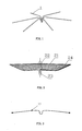
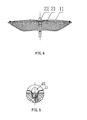
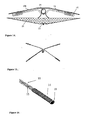
- the present invention provides a heart septal defect occlusion device for occluding an anatomical aperture, such as a patent foramen ovale occluder shown in FIGS. 2 and 4 .
- the occluder comprises a right disc 21 (which can be a metal mesh disc), tip 22, joint 23, and left disc 1 which is covered with membranes, and membranes 100, as shown in FIG. 1 and FIG. 9 .
- the present invention will be described using a PFO occluder as an example.
- the maximal character of the PFO occluder when compared with those of the above-referenced patents, is that the left disc 1 comprises six skeletons 11 which are spaced apart evenly. And the six skeletons are linked together in the center and form a radially-extending disc. It is possible that the left disc 1 may comprise at least two skeletons 11 as shown in FIG. 3 , and skeleton 11 is made from nitinol wire with shape memory.
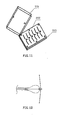
- FIG. 11 I illustrates the mould which is used to heat treat skeletons 11.
- the mould includes upper-mould 201, middle-mould 202 and under-mould 203 and the nitinol wire will be put into the rabbet of the middle-mould 202.
- the crystal structure of the nitinol wire can be reset in the austenitic phase, and this will tend to "set" the shape of the device, (i.e., it can keep the shape when it is fixed in the mould).
- the wire can keep the "set” shape even if cooled, and when the outside force is withdrawn, it can resume its original shape.
- the middle segment of the skeleton 11 is U-shaped, and the depth of each U- trough is different.
- these skeletons can form a plane after they have been overlapped together.
- the skeletons 11 are then covered with membranes to form the left disc 1.
- the right disc 21 of the PFO occluder uses moulding components. First, the suitable tubular metal mesh of the PFO occluder is formed by weaving or laser carving, then the tubular metal mesh is inserted into the mould and undergoes heat treatment. The tip 22 and joint 23 are then welded to the disc as shown in FIG. 2 .
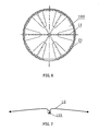
- the skeleton 11 as shown in FIG. 3 is passed through the right disc 21 and near the tip 22, and then a double-disc structure is formed as shown in FIG. 5 . And as shown in FIG. 6 , the skeletons 11 are spaced apart evenly. Accordingly, these skeletons 11 form a metal disc as shown in FIG. 4 .
- FIG. 9 illustrates the skeleton 11 with covered membranes 100.
- the membranes are made from biocompatible materials. As described above, the spheres of each skeleton are wrapped in the biocompatible materials, so that it can prevent skeleton 11 from puncturing the membranes 100.
- Another membrane made by biocompatible material 24 is filled into the right disc 21.
- FIG. 7 illustrates another embodiment of a skeleton 11 having a plurality of separate spokes 12 connected (e.g., by welding or clamping) to a central cap 121
- FIG. 8 illustrates yet another embodiment where a plurality of spokes 13 are attached directly on a tip 22 which can be the same as the tip 22 shown in FIGS. 2 , 4 and 5 .
- the occlusion device as described above may be extended and put into a catheter, and is delivered to the desired location, then is released.
- the tapered waist of the device not only ensures its self-centricity but also can reduce the probability of bad occlusion effect resulting from selection error.
- the left disc 1 which comprises skeletons and membranes, can decrease metal surface areas, thereby decreasing thrombus formation as well as harmful elements.
- the two discs are both individual components and can deploy completely after release of the occlusion device, and this can avoid forming a cucurbit shape and increase the reliability of the desired occlusion.
- FIG. 12 and FIG. 13 illustrate the deployment process of an FPO occluder and an ASD occluder during operation respectively. Moreover, the occluder has excellent self-centricity because the right disc 21 is close to the left disc 1.
- the present invention is also suitable for treating PDA and VSD etc.
- the only difference from the above other occluders is that the metal mesh of the PDA occluder of the present invention will not form a disc, but a "waist".
- FIG. 14 illustrates a modified occlusion device where the primary change is in the construction of the skeleton.
- a soft coil 14 is attached to both end segments of each skeleton 11 so that the coil 14 wraps the end segment like an envelope.
- the coil 14 can be wound with a stainless steel wire, and its outer (i.e., distal) end is welded with the corresponding end of the skeleton 11.
- the length of each coil 14 can be selected between 10-80% of the length of half of the skeleton 11 (since each half of a skeleton 11 has a separate coil 14), and its pitch is carefully chosen to adjust its flexibility.
- the term "pitch" P refers to the distance between adjacent windings of the coil 14.
- the coil 14 has a larger thickness than the thickness of the skeleton 11, thereby increasing the contact surface area between the coil 14 and the heart tissue covered by the left disc 1. This increased contact surface area reduces the injury risk to the tissue by the end segments of the skeletons 11. In other words, providing the coils 14 at the end segments of the skeleton 11 increases the contact surface area between the left disc 1 and the heart tissue. In addition, each end segment of the skeleton 11 has improved elasticity because a coiled wire is softer than when the wire is in a straightened configuration. Compared with the embodiment of FIG. 4 , the construction of the skeleton shown in FIG. 14 otherwise remains unchanged, including the skeletons 11, the membrane 100, the joint 22, the tip 23, and the metal mesh disc 21.
- the coils 14 provide a number of benefits.
- the coils 14 provide increased contact surface area.
- the coils 14 allow for the flexibility of each skeleton 11 to be varied.
- the coils 14 provide resistance to breakage of the skeletons 11. In this regard, even if the wire(s) that make up the skeletons 11 were to break, the coil 14 at the broken skeleton segment provides protection because the coil 14 itself is not as susceptible to fracture or breakage.
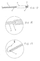
- FIG. 15 illustrates an embodiment having two crossing braided skeletons, with FIG. 16 showing the details of the end part of one such skeleton.
- the skeleton 11 can be braided with individual wires 15, with six or seven individual wires being a preferred embodiment.
- the braided skeletons shown in FIGS. 15 and 16 achieve higher fracture resistance, fatigue life and flexibility, and enable easier and more stable suture attachment for the membrane than the single wire skeletons described above.
- a single wire and a multiple-wired strand are all made from the same material and having the same total cross-sectional area, the strand will normally display a higher degree of flexibility and fatigue resistance than a single wire.
- a single-wire has a smooth surface throughout (as compared to a braided strand), thereby providing fewer locations for suturing the membranes.
- the coil 14 is wound tightly before the braided strands of the skeleton 11 are passed through the cavity or bore of the coil 14. As best seen from FIGS. 15 and 16 , the outer end of the coil 14 can be welded to the end of the braided strand to form a spherical end 16.
- FIG. 17 illustrates another modification that can be made to the skeletons shown in FIG. 14 or 15 +16.
- the inner end of the coil 14 can be wrapped with an ePTFE tape 17, in order to avoid friction between the extruding end of the coil 14 and the tissue, and to reduce the level of allergy for the tissue that contacts the skeletons 11.
- the tape 17 can be rolled like a thin tube.
- the coil 14 is positioned around the braided strand (as shown) or the single wire (not shown) of the skeleton 11, and the ePTFE tape 17 is positioned around a part of the coil 14.
- a single wire 18, which is one of the individual wires 15, can be picked up from the braided strand to wind the coil 14 around the strand.
- the other wires 15 in the strand extend to the end of the skeleton 11, while the single wire 18 is picked up before the end of the skeleton 11 and wound around the braided strand in a forward direction (i.e., distally towards the end of the skeleton 11) to form the coil 14.
- the coil 14 and the braided strand are welded together to form the spherical end 16.
- this construction and method is even easier than providing the coil 14 and the skeleton 11 as separate components, and then compressing them together during welding.
- another wire such as 18
- the other end segment is also braided with the other wires 15, and the coil 14 can be formed in the same way. Since both the strand and the coils 14 are made from the same metal (e.g., Nitinol), local galvanic corrosion will be eliminated from this part of the skeleton 11. More importantly, such unique integration of the skeleton 11 creates a reliable connection between the wires of the skeleton 11 and the coils 14. Therefore, long term durability of the left disc 1 is greatly enhanced.
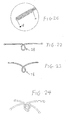
- the single wire 18 can be picked up from the stand when the strand braid is finished. More specifically, the single wire 18 is separated from the other five wires 15 of the same strand, and extends away from the end of the strand braid. The single wire 18 is wound rearwardly (i.e., proximally) from the end of the braided strand to wind the coil 14 which wraps around the end segment of the braided strand.
- FIG. 20 illustrates the completed coil 14 for the method shown in FIG. 19 . Both embodiments of FIGS. 18 and 19 ensure that the coil 14 will not be separate from the strand, thereby forming a solid skeleton 11.
- the braided strands can extend through varying lengths of the coil 14, as illustrated in FIGS. 21A-21C , to achieve varying flexibility for the end segments of the skeletons 11.
- FIG. 21A illustrates the braided strand 15 extending through the entire length of the bore of the coil 14 and having its end attached (e.g., by welding) to the spherical end 16.
- FIG. 21B illustrates the braided strand 15 extending through part of the length of the bore of the coil 14, which can be formed with one of the wires 15 as shown in FIG. 18 .
- the spherical end 16 is attached (e.g., by welding) to the end of the coil 14.
- FIG. 21A illustrates the braided strand 15 extending through the entire length of the bore of the coil 14 and having its end attached (e.g., by welding) to the spherical end 16.
- FIG. 21B illustrates the braided strand 15 extending through part of the length of the bore of the coil 14, which
- 21C illustrates the braided strand 15 terminating near the inner (i.e., proximal) end of the coil 14, but having at least one wire 19 extending through part of the length of the bore of the coil 14 which can be formed using one of the wires 15 as shown in FIG. 18 .
- the spherical end 16 is attached (e.g., by welding) to the end of the coil 14.
- the wire 19 can further extend to weld with the coil 14 at the spherical end 16, or still further extend to wind the coil 14 rearwardly as shown in FIG. 19 instead of picking up one of wires 15 to wind the coil 14 forwardly.
- the left disc 1 may have difficulty conforming to the heart anatomy with minimum injury risk.
- some complicated heart structure defects such as PFO, can cause a skewed or pulsed configuration for the left disc 1 of the occlusion device, so operation risk arises due to the U-shaped segments of the skeletons 11 shown above.
- the U-shaped segments may deform asymmetrically, and experience high local tension.
- FIGS. 1 and 5 above several U-shaped segments and the joint 22 are already crowded together, thereby allowing little space for them to get closer.
- the joint 22 will block the U-shaped segments from deforming further and also resist the movement of the skeletons 11, resulting in greater reaction force on the tissue in contact with the resisting skeletons 11. This excess pressure can cause serious injury to the heart, such as atrial fibrillation.
- the shape of the middle segments can be modified to increase flexibility, as shown in FIG. 22 , where the U-shaped segment is replaced by a looped section 28 where the skeleton 11 is twisted or looped to cross or overlap itself.
- the joint inside the looped section 28 will not hinder the looped section 28 and the skeleton arms.
- looped sections 28 can be nested within each other in a manner to form a mutually locking structure for a full set of skeletons 11 for a left disc 1. As shown in FIG. 24 , two looped skeletons cross and lock each other. Thus, the looped sections 28 allow easier bending of the skeletons 11 than the U-shaped segments, thereby significantly reducing the reaction force on the tissue and the associated injury risk.
- the occlusion device of the present invention can optionally combine different features of the above embodiments to utilize multiple advantages.
- the skeletons with looped sections, braided strands and coiled ends can produce higher flexibility and minimize injury risk.
- All metallic parts of the occlusion device can be coated with biocompatible materials, such as titanium nitride thin film, which facilitates endothelialisation and reduces thrombus risk.
- providing a sufficient thickness of ceramic coating can also reduce the harmful nickel release from Nitinol.
Landscapes
- Health & Medical Sciences (AREA)
- Surgery (AREA)
- Life Sciences & Earth Sciences (AREA)
- Medical Informatics (AREA)
- Nuclear Medicine, Radiotherapy & Molecular Imaging (AREA)
- Engineering & Computer Science (AREA)
- Biomedical Technology (AREA)
- Heart & Thoracic Surgery (AREA)
- Cardiology (AREA)
- Molecular Biology (AREA)
- Animal Behavior & Ethology (AREA)
- General Health & Medical Sciences (AREA)
- Public Health (AREA)
- Veterinary Medicine (AREA)
- Surgical Instruments (AREA)
- Prostheses (AREA)
Applications Claiming Priority (1)
| Application Number | Priority Date | Filing Date | Title |
|---|---|---|---|
| US12/927,194 US8366743B2 (en) | 2005-01-28 | 2010-11-08 | Heart septal defect occlusion device |
Publications (3)
| Publication Number | Publication Date |
|---|---|
| EP2449971A2 true EP2449971A2 (de) | 2012-05-09 |
| EP2449971A3 EP2449971A3 (de) | 2012-06-20 |
| EP2449971B1 EP2449971B1 (de) | 2019-05-29 |
Family
ID=43531862
Family Applications (1)
| Application Number | Title | Priority Date | Filing Date |
|---|---|---|---|
| EP10015699.1A Active EP2449971B1 (de) | 2010-11-08 | 2010-12-15 | Verschlusseinrichtung eines Septumschadens |
Country Status (2)
| Country | Link |
|---|---|
| US (1) | US8366743B2 (de) |
| EP (1) | EP2449971B1 (de) |
Families Citing this family (16)
| Publication number | Priority date | Publication date | Assignee | Title |
|---|---|---|---|---|
| US8617205B2 (en) | 2007-02-01 | 2013-12-31 | Cook Medical Technologies Llc | Closure device |
| US10219796B2 (en) | 2009-02-21 | 2019-03-05 | Farideh Roshanali | Device for percutaneous transcathertral closure of atrial septal defect by deploying pericardial patch |
| EP2627265B8 (de) | 2010-10-15 | 2019-02-20 | Cook Medical Technologies LLC | Okklusionsvorrichtung zum blockieren des flüssigkeitsflusses durch körperdurchgänge |
| CA145430S (en) * | 2011-10-31 | 2013-01-25 | Occlutech Holding Ag | Occlusion device |
| EP3281608B1 (de) | 2012-02-10 | 2020-09-16 | CVDevices, LLC | Produit medical contenant une armature et plèvre viscérale |
| USD727501S1 (en) * | 2012-04-30 | 2015-04-21 | Occlutech Holdings AG | Occlusion devices |
| USD728102S1 (en) * | 2012-04-30 | 2015-04-28 | Occlutech Holding Ag | Occlusion device |
| USD727500S1 (en) * | 2012-04-30 | 2015-04-21 | Occlutech Holding Ag | Occlusion device |
| EP2740412B1 (de) * | 2012-12-10 | 2016-01-20 | Peter Osypka Stiftung | Implantierbares Verschlusssystem mit membranbespanntem Formgedächtnisgeflecht |
| CN104905828B (zh) * | 2013-02-04 | 2018-08-07 | 先健科技(深圳)有限公司 | 一种具有可变夹角的扁平盘面的封堵器 |
| WO2014124356A2 (en) | 2013-02-11 | 2014-08-14 | Cook Medical Technologies Llc | Expandable support frame and medical device |
| WO2015112971A1 (en) | 2014-01-27 | 2015-07-30 | Children's Medical Center Corporation | Mechanical assist device |
| CN106923886B (zh) * | 2015-12-31 | 2022-04-22 | 先健科技(深圳)有限公司 | 左心耳封堵器 |
| US12402885B2 (en) | 2017-09-23 | 2025-09-02 | Universität Zürich | Medical occlusion device |
| EP3459469A1 (de) | 2017-09-23 | 2019-03-27 | Universität Zürich | Medizinische okklusionsvorrichtung |
| EP4033999B1 (de) | 2019-09-26 | 2024-11-27 | Universität Zürich | Verschlussvorrichtungen für das linke herzohr |
Family Cites Families (25)
| Publication number | Priority date | Publication date | Assignee | Title |
|---|---|---|---|---|
| US3874388A (en) * | 1973-02-12 | 1975-04-01 | Ochsner Med Found Alton | Shunt defect closure system |
| US5152777A (en) * | 1989-01-25 | 1992-10-06 | Uresil Corporation | Device and method for providing protection from emboli and preventing occulsion of blood vessels |
| EP0545091B1 (de) * | 1991-11-05 | 1999-07-07 | The Children's Medical Center Corporation | Okklusionsvorrichtung zur Reparatur von Herz- und Gefäss-Defekten |
| WO1993017635A1 (en) * | 1992-03-04 | 1993-09-16 | C.R. Bard, Inc. | Composite prosthesis and method for limiting the incidence of postoperative adhesions |
| US6346074B1 (en) * | 1993-02-22 | 2002-02-12 | Heartport, Inc. | Devices for less invasive intracardiac interventions |
| WO1995027448A1 (en) * | 1994-04-06 | 1995-10-19 | William Cook Europe A/S | A medical article for implantation into the vascular system of a patient |
| RU2157146C2 (ru) * | 1995-06-13 | 2000-10-10 | ВИЛЬЯМ КУК Европа, A/S | Устройство для имплантации в сосудах и полых органах (его варианты) |
| US5944738A (en) * | 1998-02-06 | 1999-08-31 | Aga Medical Corporation | Percutaneous catheter directed constricting occlusion device |
| US6368338B1 (en) * | 1999-03-05 | 2002-04-09 | Board Of Regents, The University Of Texas | Occlusion method and apparatus |
| US6712836B1 (en) * | 1999-05-13 | 2004-03-30 | St. Jude Medical Atg, Inc. | Apparatus and methods for closing septal defects and occluding blood flow |
| US6656206B2 (en) * | 1999-05-13 | 2003-12-02 | Cardia, Inc. | Occlusion device with non-thrombogenic properties |
| US6273901B1 (en) * | 1999-08-10 | 2001-08-14 | Scimed Life Systems, Inc. | Thrombosis filter having a surface treatment |
| CN2430113Y (zh) | 2000-08-28 | 2001-05-16 | 曾国洪 | 一次性使用心脏及血管内异常通道封堵器 |
| PT1345556E (pt) * | 2000-11-25 | 2008-12-16 | Univ Texas | Dispositivos de oclusão |
| CN1190176C (zh) | 2002-03-06 | 2005-02-23 | 深圳市先健科技股份有限公司 | 室间隔缺损堵闭器及其制造方法 |
| CN2566817Y (zh) | 2002-09-12 | 2003-08-20 | 深圳市先健科技股份有限公司 | 室间隔缺损堵闭器 |
| CN2661130Y (zh) | 2003-06-12 | 2004-12-08 | 深圳市先健科技股份有限公司 | 全包膜心脏间隔缺损封堵器 |
| US7144410B2 (en) * | 2003-09-18 | 2006-12-05 | Cardia Inc. | ASD closure device with self centering arm network |
| US7658748B2 (en) * | 2003-09-23 | 2010-02-09 | Cardia, Inc. | Right retrieval mechanism |
| AU2004279466A1 (en) | 2003-10-10 | 2005-04-21 | Proximare, Inc. | Patent foramen ovale (PFO) closure devices, delivery apparatus and related methods and systems |
| US7959645B2 (en) * | 2004-11-03 | 2011-06-14 | Boston Scientific Scimed, Inc. | Retrievable vena cava filter |
| US20060217760A1 (en) * | 2005-03-17 | 2006-09-28 | Widomski David R | Multi-strand septal occluder |
| US8372113B2 (en) * | 2005-03-24 | 2013-02-12 | W.L. Gore & Associates, Inc. | Curved arm intracardiac occluder |
| WO2006104147A1 (ja) * | 2005-03-29 | 2006-10-05 | Terumo Kabushiki Kaisha | 欠損閉鎖デバイスとデリバリ装置 |
| EP1842490B1 (de) * | 2006-04-07 | 2011-09-14 | Lifetech Scientific (Shenzhen) Co., Ltd. | Selbstanpassende Verschlussvorrichtung zur Behandlung einer angeborenen Herzkrankheit |
-
2010
- 2010-11-08 US US12/927,194 patent/US8366743B2/en not_active Expired - Lifetime
- 2010-12-15 EP EP10015699.1A patent/EP2449971B1/de active Active
Also Published As
| Publication number | Publication date |
|---|---|
| EP2449971B1 (de) | 2019-05-29 |
| US20110066180A1 (en) | 2011-03-17 |
| EP2449971A3 (de) | 2012-06-20 |
| US8366743B2 (en) | 2013-02-05 |
Similar Documents
| Publication | Publication Date | Title |
|---|---|---|
| US8366743B2 (en) | Heart septal defect occlusion device | |
| US10624619B2 (en) | Multi-layer braided structures for occluding vascular defects and for occluding fluid flow through portions of the vasculature of the body | |
| EP1576929B1 (de) | Mehrschichtige geflochtene Strukturen zum Verschliessen von Gefässdefekten | |
| AU2011352999B2 (en) | Left atrial appendage occlusive devices | |
| JP6306503B2 (ja) | 閉鎖デバイス及び関連した展開方法 | |
| JP6154394B2 (ja) | 患者の脈管構造における異常な開口部を閉塞する機器および方法 | |
| EP2004065B1 (de) | Rohrförmige verschlussvorrichtung für offenes foramen ovale mit sperrsystem | |
| EP3202333A1 (de) | Mehrschichtige flechtstrukturen zum verschliessen von gefässdefekten | |
| US20110054519A1 (en) | Device for closing defects in the vascular system | |
| US20130144332A1 (en) | Curved Arm Intracardiac Occluder | |
| US20060217760A1 (en) | Multi-strand septal occluder | |
| JP2012000471A (ja) | 捕捉システムを有する管状の卵円孔開存(pfo)閉鎖デバイス | |
| HK1148185B (en) | Multi-layer braided structures for occluding vascular defects | |
| HK1077990B (en) | An intravascular device for occluding vascular defects |
Legal Events
| Date | Code | Title | Description |
|---|---|---|---|
| PUAI | Public reference made under article 153(3) epc to a published international application that has entered the european phase |
Free format text: ORIGINAL CODE: 0009012 |
|
| AK | Designated contracting states |
Kind code of ref document: A2 Designated state(s): AL AT BE BG CH CY CZ DE DK EE ES FI FR GB GR HR HU IE IS IT LI LT LU LV MC MK MT NL NO PL PT RO RS SE SI SK SM TR |
|
| AX | Request for extension of the european patent |
Extension state: BA ME |
|
| PUAL | Search report despatched |
Free format text: ORIGINAL CODE: 0009013 |
|
| AK | Designated contracting states |
Kind code of ref document: A3 Designated state(s): AL AT BE BG CH CY CZ DE DK EE ES FI FR GB GR HR HU IE IS IT LI LT LU LV MC MK MT NL NO PL PT RO RS SE SI SK SM TR |
|
| AX | Request for extension of the european patent |
Extension state: BA ME |
|
| RIC1 | Information provided on ipc code assigned before grant |
Ipc: A61B 17/00 20060101AFI20120515BHEP |
|
| 17P | Request for examination filed |
Effective date: 20121220 |
|
| STAA | Information on the status of an ep patent application or granted ep patent |
Free format text: STATUS: EXAMINATION IS IN PROGRESS |
|
| 17Q | First examination report despatched |
Effective date: 20180628 |
|
| GRAP | Despatch of communication of intention to grant a patent |
Free format text: ORIGINAL CODE: EPIDOSNIGR1 |
|
| STAA | Information on the status of an ep patent application or granted ep patent |
Free format text: STATUS: GRANT OF PATENT IS INTENDED |
|
| INTG | Intention to grant announced |
Effective date: 20190102 |
|
| GRAS | Grant fee paid |
Free format text: ORIGINAL CODE: EPIDOSNIGR3 |
|
| GRAA | (expected) grant |
Free format text: ORIGINAL CODE: 0009210 |
|
| STAA | Information on the status of an ep patent application or granted ep patent |
Free format text: STATUS: THE PATENT HAS BEEN GRANTED |
|
| AK | Designated contracting states |
Kind code of ref document: B1 Designated state(s): AL AT BE BG CH CY CZ DE DK EE ES FI FR GB GR HR HU IE IS IT LI LT LU LV MC MK MT NL NO PL PT RO RS SE SI SK SM TR |
|
| REG | Reference to a national code |
Ref country code: GB Ref legal event code: FG4D |
|
| REG | Reference to a national code |
Ref country code: CH Ref legal event code: EP |
|
| REG | Reference to a national code |
Ref country code: AT Ref legal event code: REF Ref document number: 1137787 Country of ref document: AT Kind code of ref document: T Effective date: 20190615 |
|
| REG | Reference to a national code |
Ref country code: DE Ref legal event code: R096 Ref document number: 602010059146 Country of ref document: DE |
|
| REG | Reference to a national code |
Ref country code: IE Ref legal event code: FG4D |
|
| REG | Reference to a national code |
Ref country code: NL Ref legal event code: MP Effective date: 20190529 |
|
| REG | Reference to a national code |
Ref country code: LT Ref legal event code: MG4D |
|
| PG25 | Lapsed in a contracting state [announced via postgrant information from national office to epo] |
Ref country code: SE Free format text: LAPSE BECAUSE OF FAILURE TO SUBMIT A TRANSLATION OF THE DESCRIPTION OR TO PAY THE FEE WITHIN THE PRESCRIBED TIME-LIMIT Effective date: 20190529 Ref country code: HR Free format text: LAPSE BECAUSE OF FAILURE TO SUBMIT A TRANSLATION OF THE DESCRIPTION OR TO PAY THE FEE WITHIN THE PRESCRIBED TIME-LIMIT Effective date: 20190529 Ref country code: LT Free format text: LAPSE BECAUSE OF FAILURE TO SUBMIT A TRANSLATION OF THE DESCRIPTION OR TO PAY THE FEE WITHIN THE PRESCRIBED TIME-LIMIT Effective date: 20190529 Ref country code: ES Free format text: LAPSE BECAUSE OF FAILURE TO SUBMIT A TRANSLATION OF THE DESCRIPTION OR TO PAY THE FEE WITHIN THE PRESCRIBED TIME-LIMIT Effective date: 20190529 Ref country code: PT Free format text: LAPSE BECAUSE OF FAILURE TO SUBMIT A TRANSLATION OF THE DESCRIPTION OR TO PAY THE FEE WITHIN THE PRESCRIBED TIME-LIMIT Effective date: 20190930 Ref country code: NO Free format text: LAPSE BECAUSE OF FAILURE TO SUBMIT A TRANSLATION OF THE DESCRIPTION OR TO PAY THE FEE WITHIN THE PRESCRIBED TIME-LIMIT Effective date: 20190829 Ref country code: AL Free format text: LAPSE BECAUSE OF FAILURE TO SUBMIT A TRANSLATION OF THE DESCRIPTION OR TO PAY THE FEE WITHIN THE PRESCRIBED TIME-LIMIT Effective date: 20190529 Ref country code: FI Free format text: LAPSE BECAUSE OF FAILURE TO SUBMIT A TRANSLATION OF THE DESCRIPTION OR TO PAY THE FEE WITHIN THE PRESCRIBED TIME-LIMIT Effective date: 20190529 |
|
| PG25 | Lapsed in a contracting state [announced via postgrant information from national office to epo] |
Ref country code: BG Free format text: LAPSE BECAUSE OF FAILURE TO SUBMIT A TRANSLATION OF THE DESCRIPTION OR TO PAY THE FEE WITHIN THE PRESCRIBED TIME-LIMIT Effective date: 20190829 Ref country code: RS Free format text: LAPSE BECAUSE OF FAILURE TO SUBMIT A TRANSLATION OF THE DESCRIPTION OR TO PAY THE FEE WITHIN THE PRESCRIBED TIME-LIMIT Effective date: 20190529 Ref country code: LV Free format text: LAPSE BECAUSE OF FAILURE TO SUBMIT A TRANSLATION OF THE DESCRIPTION OR TO PAY THE FEE WITHIN THE PRESCRIBED TIME-LIMIT Effective date: 20190529 Ref country code: GR Free format text: LAPSE BECAUSE OF FAILURE TO SUBMIT A TRANSLATION OF THE DESCRIPTION OR TO PAY THE FEE WITHIN THE PRESCRIBED TIME-LIMIT Effective date: 20190830 |
|
| REG | Reference to a national code |
Ref country code: AT Ref legal event code: MK05 Ref document number: 1137787 Country of ref document: AT Kind code of ref document: T Effective date: 20190529 |
|
| PG25 | Lapsed in a contracting state [announced via postgrant information from national office to epo] |
Ref country code: DK Free format text: LAPSE BECAUSE OF FAILURE TO SUBMIT A TRANSLATION OF THE DESCRIPTION OR TO PAY THE FEE WITHIN THE PRESCRIBED TIME-LIMIT Effective date: 20190529 Ref country code: NL Free format text: LAPSE BECAUSE OF FAILURE TO SUBMIT A TRANSLATION OF THE DESCRIPTION OR TO PAY THE FEE WITHIN THE PRESCRIBED TIME-LIMIT Effective date: 20190529 Ref country code: SK Free format text: LAPSE BECAUSE OF FAILURE TO SUBMIT A TRANSLATION OF THE DESCRIPTION OR TO PAY THE FEE WITHIN THE PRESCRIBED TIME-LIMIT Effective date: 20190529 Ref country code: CZ Free format text: LAPSE BECAUSE OF FAILURE TO SUBMIT A TRANSLATION OF THE DESCRIPTION OR TO PAY THE FEE WITHIN THE PRESCRIBED TIME-LIMIT Effective date: 20190529 Ref country code: RO Free format text: LAPSE BECAUSE OF FAILURE TO SUBMIT A TRANSLATION OF THE DESCRIPTION OR TO PAY THE FEE WITHIN THE PRESCRIBED TIME-LIMIT Effective date: 20190529 Ref country code: EE Free format text: LAPSE BECAUSE OF FAILURE TO SUBMIT A TRANSLATION OF THE DESCRIPTION OR TO PAY THE FEE WITHIN THE PRESCRIBED TIME-LIMIT Effective date: 20190529 Ref country code: AT Free format text: LAPSE BECAUSE OF FAILURE TO SUBMIT A TRANSLATION OF THE DESCRIPTION OR TO PAY THE FEE WITHIN THE PRESCRIBED TIME-LIMIT Effective date: 20190529 |
|
| PG25 | Lapsed in a contracting state [announced via postgrant information from national office to epo] |
Ref country code: SM Free format text: LAPSE BECAUSE OF FAILURE TO SUBMIT A TRANSLATION OF THE DESCRIPTION OR TO PAY THE FEE WITHIN THE PRESCRIBED TIME-LIMIT Effective date: 20190529 Ref country code: IT Free format text: LAPSE BECAUSE OF FAILURE TO SUBMIT A TRANSLATION OF THE DESCRIPTION OR TO PAY THE FEE WITHIN THE PRESCRIBED TIME-LIMIT Effective date: 20190529 |
|
| REG | Reference to a national code |
Ref country code: DE Ref legal event code: R097 Ref document number: 602010059146 Country of ref document: DE |
|
| PG25 | Lapsed in a contracting state [announced via postgrant information from national office to epo] |
Ref country code: TR Free format text: LAPSE BECAUSE OF FAILURE TO SUBMIT A TRANSLATION OF THE DESCRIPTION OR TO PAY THE FEE WITHIN THE PRESCRIBED TIME-LIMIT Effective date: 20190529 |
|
| PLBE | No opposition filed within time limit |
Free format text: ORIGINAL CODE: 0009261 |
|
| STAA | Information on the status of an ep patent application or granted ep patent |
Free format text: STATUS: NO OPPOSITION FILED WITHIN TIME LIMIT |
|
| PG25 | Lapsed in a contracting state [announced via postgrant information from national office to epo] |
Ref country code: PL Free format text: LAPSE BECAUSE OF FAILURE TO SUBMIT A TRANSLATION OF THE DESCRIPTION OR TO PAY THE FEE WITHIN THE PRESCRIBED TIME-LIMIT Effective date: 20190529 |
|
| 26N | No opposition filed |
Effective date: 20200303 |
|
| PG25 | Lapsed in a contracting state [announced via postgrant information from national office to epo] |
Ref country code: SI Free format text: LAPSE BECAUSE OF FAILURE TO SUBMIT A TRANSLATION OF THE DESCRIPTION OR TO PAY THE FEE WITHIN THE PRESCRIBED TIME-LIMIT Effective date: 20190529 |
|
| REG | Reference to a national code |
Ref country code: CH Ref legal event code: PL |
|
| REG | Reference to a national code |
Ref country code: BE Ref legal event code: MM Effective date: 20191231 |
|
| PG25 | Lapsed in a contracting state [announced via postgrant information from national office to epo] |
Ref country code: MC Free format text: LAPSE BECAUSE OF FAILURE TO SUBMIT A TRANSLATION OF THE DESCRIPTION OR TO PAY THE FEE WITHIN THE PRESCRIBED TIME-LIMIT Effective date: 20190529 |
|
| GBPC | Gb: european patent ceased through non-payment of renewal fee |
Effective date: 20191215 |
|
| PG25 | Lapsed in a contracting state [announced via postgrant information from national office to epo] |
Ref country code: FR Free format text: LAPSE BECAUSE OF NON-PAYMENT OF DUE FEES Effective date: 20191231 Ref country code: LU Free format text: LAPSE BECAUSE OF NON-PAYMENT OF DUE FEES Effective date: 20191215 Ref country code: GB Free format text: LAPSE BECAUSE OF NON-PAYMENT OF DUE FEES Effective date: 20191215 Ref country code: IE Free format text: LAPSE BECAUSE OF NON-PAYMENT OF DUE FEES Effective date: 20191215 |
|
| PG25 | Lapsed in a contracting state [announced via postgrant information from national office to epo] |
Ref country code: BE Free format text: LAPSE BECAUSE OF NON-PAYMENT OF DUE FEES Effective date: 20191231 Ref country code: LI Free format text: LAPSE BECAUSE OF NON-PAYMENT OF DUE FEES Effective date: 20191231 Ref country code: CH Free format text: LAPSE BECAUSE OF NON-PAYMENT OF DUE FEES Effective date: 20191231 |
|
| PG25 | Lapsed in a contracting state [announced via postgrant information from national office to epo] |
Ref country code: CY Free format text: LAPSE BECAUSE OF FAILURE TO SUBMIT A TRANSLATION OF THE DESCRIPTION OR TO PAY THE FEE WITHIN THE PRESCRIBED TIME-LIMIT Effective date: 20190529 |
|
| PG25 | Lapsed in a contracting state [announced via postgrant information from national office to epo] |
Ref country code: IS Free format text: LAPSE BECAUSE OF FAILURE TO SUBMIT A TRANSLATION OF THE DESCRIPTION OR TO PAY THE FEE WITHIN THE PRESCRIBED TIME-LIMIT Effective date: 20190929 |
|
| PG25 | Lapsed in a contracting state [announced via postgrant information from national office to epo] |
Ref country code: MT Free format text: LAPSE BECAUSE OF FAILURE TO SUBMIT A TRANSLATION OF THE DESCRIPTION OR TO PAY THE FEE WITHIN THE PRESCRIBED TIME-LIMIT Effective date: 20190529 Ref country code: HU Free format text: LAPSE BECAUSE OF FAILURE TO SUBMIT A TRANSLATION OF THE DESCRIPTION OR TO PAY THE FEE WITHIN THE PRESCRIBED TIME-LIMIT; INVALID AB INITIO Effective date: 20101215 |
|
| PG25 | Lapsed in a contracting state [announced via postgrant information from national office to epo] |
Ref country code: MK Free format text: LAPSE BECAUSE OF FAILURE TO SUBMIT A TRANSLATION OF THE DESCRIPTION OR TO PAY THE FEE WITHIN THE PRESCRIBED TIME-LIMIT Effective date: 20190529 |
|
| P01 | Opt-out of the competence of the unified patent court (upc) registered |
Effective date: 20230515 |
|
| PGFP | Annual fee paid to national office [announced via postgrant information from national office to epo] |
Ref country code: DE Payment date: 20241211 Year of fee payment: 15 |