EP2448791B1 - Antriebseinheit einer scheibenwischvorrichtung in einem fahrzeug - Google Patents
Antriebseinheit einer scheibenwischvorrichtung in einem fahrzeug Download PDFInfo
- Publication number
- EP2448791B1 EP2448791B1 EP10720283.0A EP10720283A EP2448791B1 EP 2448791 B1 EP2448791 B1 EP 2448791B1 EP 10720283 A EP10720283 A EP 10720283A EP 2448791 B1 EP2448791 B1 EP 2448791B1
- Authority
- EP
- European Patent Office
- Prior art keywords
- wiper
- output shaft
- drive unit
- coupling section
- test
- Prior art date
- Legal status (The legal status is an assumption and is not a legal conclusion. Google has not performed a legal analysis and makes no representation as to the accuracy of the status listed.)
- Not-in-force
Links
- 230000008878 coupling Effects 0.000 claims description 32
- 238000010168 coupling process Methods 0.000 claims description 32
- 238000005859 coupling reaction Methods 0.000 claims description 32
- 238000012360 testing method Methods 0.000 claims description 18
- 230000007704 transition Effects 0.000 claims description 2
- 230000005540 biological transmission Effects 0.000 description 3
- 238000013461 design Methods 0.000 description 2
- 238000011056 performance test Methods 0.000 description 2
- 230000004323 axial length Effects 0.000 description 1
- 230000001419 dependent effect Effects 0.000 description 1
- 238000011161 development Methods 0.000 description 1
- 230000018109 developmental process Effects 0.000 description 1
- 238000011990 functional testing Methods 0.000 description 1
- 238000009434 installation Methods 0.000 description 1
- 238000012545 processing Methods 0.000 description 1
Images

Classifications
-
- B—PERFORMING OPERATIONS; TRANSPORTING
- B60—VEHICLES IN GENERAL
- B60S—SERVICING, CLEANING, REPAIRING, SUPPORTING, LIFTING, OR MANOEUVRING OF VEHICLES, NOT OTHERWISE PROVIDED FOR
- B60S1/00—Cleaning of vehicles
- B60S1/02—Cleaning windscreens, windows or optical devices
- B60S1/04—Wipers or the like, e.g. scrapers
- B60S1/06—Wipers or the like, e.g. scrapers characterised by the drive
- B60S1/16—Means for transmitting drive
-
- B—PERFORMING OPERATIONS; TRANSPORTING
- B60—VEHICLES IN GENERAL
- B60S—SERVICING, CLEANING, REPAIRING, SUPPORTING, LIFTING, OR MANOEUVRING OF VEHICLES, NOT OTHERWISE PROVIDED FOR
- B60S1/00—Cleaning of vehicles
- B60S1/02—Cleaning windscreens, windows or optical devices
- B60S1/04—Wipers or the like, e.g. scrapers
- B60S1/0452—Position of the wipers relative to the vehicle
- B60S1/0469—Devices for assisting the wiper positioning on the vehicle
Definitions
- the invention relates to a drive unit of a windshield wiper device in a vehicle according to the preamble of claim 1.
- the DE 103 13 734 A1 discloses a windshield wiper device with a drive unit which comprises in a common housing an electric drive motor and a transmission.
- the transmission is provided with an output shaft which is driven by the electric drive motor and is connected to a linkage part of a wiper linkage.
- the engine rotational movement is converted into a pendulum rotational movement of a wiper arm of the wiper linkage.
- the coupling between the output shaft and the rod part of the wiper linkage takes place in known embodiments via a conical portion on the lateral surface of the output shaft, which has a knurled surface for increasing the friction. It should be noted that the surface must not be damaged during assembly and when checking the drive motor in order not to endanger the secure coupling between the output shaft and the linkage.
- the invention is based on the object with simple constructive measures to form a drive unit of a windscreen wiper device in such a way that a secure connection of the output shaft is guaranteed to a wiper linkage.
- the drive unit according to the invention is used in windshield wiper devices in motor vehicles, for example as a windshield wiper device or as a rear window wiper device.
- the drive unit of the windscreen wiper device comprises an electric drive motor, which is expediently assigned a gear arrangement in a common housing, which has an output shaft, which in the mounted state is coupled to a wiper linkage part, in particular an engine crankshaft.
- a wiper linkage part in particular an engine crankshaft.
- the wiper linkage is actuated to drive a wiper arm.
- the connection between the output shaft and the wiper linkage part via a wiper coupling portion on the lateral surface of the output shaft. At this wiper coupling portion engages the wiper linkage part, which is suitably rotatably connected to the output shaft via the wiper coupling portion.
- a test coupling section which serves to connect the output shaft to a test stand component, is formed on the output shaft in addition to the wiper coupling section.
- the output shaft of the drive unit is connected to the test stand, wherein the drive motor has to apply a torque to overcome a resistance generated by the test stand.
- the torque is transmitted via the test coupling section of the output shaft, it being ensured on the basis of the separate execution of wiper coupling section and test coupling section that the functional test of the drive motor does not lead to damage of the wiper coupling section. In this way, a secure and firm connection between the output shaft and the wiper linkage is ensured after the installation of the drive unit.
- the sketchkoppelabites is formed as a form-fitting portion having a non-rotationally symmetrical cross-sectional geometry, on which a corresponding counterpart positively engages, so that in the direction of rotation about the axis of the output shaft a positive connection is formed.
- the form-fitting portion may be located on the outer circumferential surface of the output shaft.
- the form-fitting section is designed as a recess in the end face of the output shaft and has a positive-locking geometry which is designed as an inner torx or inner polygon.
- a correspondingly shaped counterpart can engage positively.
- the design as a recess on the end face of the output shaft has the advantage that the lateral surface of the output shaft requires no further processing and that, moreover, a space-saving design for the educakoppelabites is given.
- the wiper coupling portion preferably has a knurled surface on which a wiper linkage part, in particular a crank of the wiper linkage is placed and firmly connected.
- This knurled portion is preferably located on a cone-shaped portion that lies in the transition between two cylinder portions of the output shaft with different diameter.
- On the conical portion a complementarily shaped recess in the respective wiper linkage part is placed.
- the wiper coupling section and the test coupling section are axially spaced from one another so that an intermediate axial region lies between these sections.
- an intermediate axial region lies between these sections.
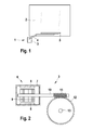
- the windscreen wiper device 1 comprises a drive unit 3 and a wiper linkage, to which a wiper arm 4 with a wiper blade 5 arranged thereon is assigned, which rests on the vehicle window 2 during operation.
- the drive unit 3 comprises an electric drive motor 6 and a gear consisting of a worm 11 and a worm wheel 12 meshing therewith.
- the worm 11 is rotatably connected to the rotor shaft 10 of the drive motor, which carries a Bestrombare coil 9, which in the pole housing 7 rotates with arranged on the inner wall of the pole housing permanent magnet 8.
- the worm wheel 12 is rotatably coupled to an output shaft 13, via which the rotational movement is transmitted to the wiper linkage.
- the output shaft 13 is rotatably coupled for this purpose with a linkage part of the wiper linkage.
- the output shaft 13 over its axial length to various sections, which serve for connection to various components of the windshield wiper device or a test stand.
- the output shaft 13 has a first knurled portion 14, which is arranged adjacent to an end face of the output shaft and via which the rotationally fixed coupling to the worm wheel 12 (FIG. Fig. 2 ) he follows. Adjacent to the opposite end face is located between two cylindrical portions 17 and 18 of different diameters a conical wiper coupling portion 15, which is also provided with a knurled surface. About the wiper coupling portion 15, the rotationally fixed connection to a crank or a linkage part of the wiper linkage takes place.
- the wiper coupling portion 15 is at an axial distance to the end face of the output shaft 13, in which a digitizkoppelabites 16 is introduced in the form of a positive connection portion.
- the form-fit portion is formed as an axially extending recess in the end face of the output shaft 13 and has in the embodiment, the star-shaped cross-sectional geometry of an devistorx 16, in principle, other non-rotationally symmetrical cross-sectional geometries such as a polygon socket into consideration.
- a component with a corresponding cross-sectional geometry can be introduced to produce in this way a positive, further connection, in particular to a test bench, via which a performance test of the drive motor can be performed.
- Wiper coupling portion 15 and educable 16 are formed separately and independently, which has the advantage that the knurled surface of the wiper coupling portion 15 remains undamaged during the connection of the output shaft 13 to the test stand.
- the connection between the output shaft and the test rig component is released and the drive unit can be used with the windshield wiper device in the vehicle, with a secure and permanent connection of the output shaft 13 is ensured via the wiper coupling portion 15 with the component of the wiper linkage ,
Landscapes
- Engineering & Computer Science (AREA)
- Mechanical Engineering (AREA)
- Connection Of Motors, Electrical Generators, Mechanical Devices, And The Like (AREA)
Description
- Die Erfindung bezieht sich auf eine Antriebseinheit einer Scheibenwischvorrichtung in einem Fahrzeug nach dem Oberbegriff des Anspruches 1.
- Die
DE 103 13 734 A1 offenbart eine Scheibenwischvorrichtung mit einer Antriebseinheit, die in einem gemeinsamen Gehäuse einen elektrischen Antriebsmotor sowie ein Getriebe umfasst. Das Getriebe ist mit einer Abtriebswelle versehen, die von dem elektrischen Antriebsmotor angetrieben wird und mit einem Gestängeteil eines Wischergestänges verbunden ist. Im Betrieb des Motors wird die Motordrehbewegung in eine pendelnde Drehbewegung eines Wischerarms des Wischergestänges umgesetzt. - Die Kopplung zwischen der Abtriebswelle und dem Gestängeteil des Wischergestänges erfolgt bei bekannten Ausführungen über einen konusförmigen Abschnitt auf der Mantelfläche der Abtriebswelle, der eine gerändelte Oberfläche zur Reibungserhöhung aufweist. Hierbei ist zu beachten, dass die Oberfläche während der Montage und bei der Überprüfung des Antriebsmotors nicht beschädigt werden darf, um die sichere Kopplung zwischen der Abtriebswelle und dem Gestängeteil nicht zu gefährden.
- Weiterer Stand der Technik ist aus der
DE 10 2007 027 662 A1 bekannt. - Der Erfindung liegt die Aufgabe zu Grunde, mit einfachen konstruktiven Maßnahmen eine Antriebseinheit einer Scheibenwischvorrichtung in der Weise auszubilden, dass eine sichere Anbindung der Abtriebswelle an ein Wischergestängeteil gewährleistet ist.
- Diese Aufgabe wird erfindungsgemäß mit den Merkmalen des Anspruches 1 gelöst. Die Unteransprüche geben zweckmäßige Weiterbildungen an.
- Die erfindungsgemäße Antriebseinheit wird in Scheibenwischvorrichtungen in Kraftfahrzeugen eingesetzt, beispielsweise als Frontscheibenwischvorrichtung oder als Heckscheibenwischvorrichtung. Die Antriebseinheit der Scheibenwischvorrichtung umfasst einen elektrischen Antriebsmotor, dem zweckmäßigerweise eine Getriebeanordnung in einem gemeinsamen Gehäuse zugeordnet ist, welche eine Abtriebswelle aufweist, die im montierten Zustand mit einem Wischergestängeteil, insbesondere einer Motorkurbelwelle gekoppelt ist. Über das Wischergestängeteil wird das Wischergestänge zum Antrieb eines Wischerarms betätigt. Die Verbindung zwischen der Abtriebwelle und dem Wischergestängeteil erfolgt über einen Wischerkoppelabschnitt an der Mantelfläche der Abtriebswelle. An diesem Wischerkoppelabschnitt greift das Wischergestängeteil an, das zweckmäßigerweise drehfest mit der Abtriebswelle über den Wischerkoppelabschnitt verbunden ist.
- Erfindungsgemäß ist an der Abtriebswelle zusätzlich zum Wischerkoppelabschnitt ein Prüfkoppelabschnitt ausgebildet, der zur Verbindung der Abtriebswelle mit einem Prüfstandsbauteil dient. Über den Prüfkoppelabschnitt kann die Funktionstüchtigkeit der Antriebseinheit bei der Leistungsüberprüfung des Wischermotors in einem Prüfstand getestet werden. Hierbei wird die Abtriebswelle der Antriebseinheit mit dem Prüfstand verbunden, wobei der Antriebsmotor ein Drehmoment zur Überwindung eines vom Prüfstand erzeugten Widerstandes aufbringen muss. Das Drehmoment wird über den Prüfkoppelabschnitt der Abtriebswelle übertragen, wobei auf Grund der separaten Ausführung von Wischerkoppelabschnitt und Prüfkoppelabschnitt sichergestellt ist, dass die Funktionsprüfung des Antriebsmotors nicht zu einer Beschädigung des Wischerkoppelabschnittes führt. Auf diese Weise ist eine sichere und feste Verbindung zwischen der Abtriebswelle und dem Wischergestänge nach erfolgtem Einbau der Antriebseinheit sichergestellt.
- Grundsätzlich kommen verschiedene Ausführungen des Prüfkoppelabschnittes in Betracht. Bevorzugt ist der Prüfkoppelabschnitt als ein Formschlussabschnitt ausgebildet, der eine nicht-rotationssymmetrische Querschnittsgeometrie aufweist, an der ein entsprechendes Gegenstück formschlüssig angreift, so dass in Drehrichtung um die Achse der Abtriebswelle ein Formschluss gebildet ist. Der Formschlussabschnitt kann sich an der äußeren Mantelfläche der Abtriebswelle befinden. Erfindungsgemäß ist es vorgesehen, dass der Formschlussabschnitt als eine Ausnehmung in der Stirnseite der Abtriebswelle ausgeführt ist und eine Formschlussgeometrie aufweist, die als Innentorx oder Innenmehrkant ausgebildet ist. In den Innentorx bzw. Innenmehrkant an der Stirnseite der Abtriebswelle kann ein entsprechend geformtes Gegenstück formschlüssig eingreifen. Die Ausbildung als Ausnehmung an der Stirnseite der Abtriebswelle hat den Vorteil, dass die Mantelfläche der Abtriebswelle keine weitere Bearbeitung erfordert und dass zudem eine Platz sparende Ausführung für den Prüfkoppelabschnitt gegeben ist.
- Der Wischerkoppelabschnitt besitzt bevorzugt eine gerändelte Oberfläche, auf die ein Wischergestängeteil, insbesondere eine Kurbel des Wischergestänges aufgesetzt und fest verbunden wird. Dieser gerändelte Abschnitt befindet sich vorzugsweise an einem konusförmigen Bereich, der im Übergang zwischen zwei Zylinderabschnitten der Abtriebswelle mit unterschiedlichem Durchmesser liegt. Auf dem konusförmigen Abschnitt wird eine komplementär geformte Ausnehmung im betreffenden Wischergestängeteil aufgesetzt.
- Gemäß weiterer zweckmäßiger Ausführung ist vorgesehen, dass Wischerkoppelabschnitt und Prüfkoppelabschnitt axial zueinander beabstandet sind, so dass zwischen diesen Abschnitten ein zwischenliegender axialer Bereich liegt. Grundsätzlich möglich ist aber auch insbesondere in der Ausführung des Prüfkoppelabschnittes als in die Stirnseite der Abtriebswelle eingebrachte Ausnehmung eine axiale Überschneidung von Wischerkoppelabschnitt und Prüfkoppelabschnitt.
- Weitere Vorteile und zweckmäßige Ausführungen sind den weiteren Ansprüchen, der Figurenbeschreibung und den Zeichnungen zu entnehmen. Es zeigen:
- Fig. 1
- eine schematische Darstellung einer Scheibenwischvorrichtung in einem Kraftfahrzeug,
- Fig. 2
- eine Draufsicht auf eine Antriebseinheit für die Scheibenwischvorrichtung, mit einem elektrischen Antriebsmotor, der über ein Getriebe eine Abtriebswelle antreibt,
- Fig. 3
- eine perspektivische Ansicht der Abtriebswelle, die im Bereich ihrer Stirnseite mit einem Innentorx versehen ist,
- Fig. 4
- eine vergrößerte Ansicht aus dem Bereich der Stirnseite der Abtriebswelle.
- Die in
Fig. 1 gezeigte Scheibenwischvorrichtung 1 wird in Kraftfahrzeugen eingesetzt und dient zum Wischen einer Fahrzeugscheibe 2. Die Scheibenwischvorrichtung 1 umfasst eine Antriebseinheit 3 sowie ein Wischergestänge, dem ein Wischerarm 4 mit daran angeordnetem Wischblatt 5 zugeordnet ist, welches im Betrieb an der Fahrzeugscheibe 2 aufliegt. - Wie der Detaildarstellung der Antriebseinheit 3 gemäß
Fig. 2 zu entnehmen, umfasst die Antriebseinheit 3 einen elektrischen Antriebsmotor 6 sowie ein Getriebe, bestehend aus einer Schnecke 11 und einem hiermit kämmenden Schneckenrad 12. Die Schnecke 11 ist drehfest mit der Rotorwelle 10 des Antriebsmotors verbunden, die einen bestrombare Spule 9 trägt, welche im Polgehäuse 7 mit an der Innenwand des Polgehäuses angeordneten Permanentmagneten 8 umläuft. - Das Schneckenrad 12 ist drehfest mit einer Abtriebswelle 13 gekoppelt, über die die Drehbewegung auf das Wischergestänge übertragen wird. Die Abtriebswelle 13 ist zu diesem Zweck mit einem Gestängeteil des Wischergestänges drehfest gekoppelt.
- Wie
Fig. 3 sowie der vergrößerten Darstellung gemäßFig. 4 zu entnehmen, weist die Abtriebswelle 13 über ihre axiale Länge verschiedene Abschnitte auf, die zur Anbindung an verschiedene Bauteile der Scheibenwischvorrichtung bzw. eines Prüfstandes dienen. Die Abtriebswelle 13 besitzt einen ersten gerändelten Abschnitt 14, der benachbart zu einer Stirnseite der Abtriebswelle angeordnet ist und über den die drehfeste Kopplung zum Schneckenrad 12 (Fig. 2 ) erfolgt. Benachbart zur gegenüberliegenden Stirnseite befindet sich zwischen zwei zylindrischen Bereichen 17 und 18 unterschiedlichen Durchmessers ein konusförmiger Wischerkoppelabschnitt 15, der ebenfalls mit einer gerändelten Oberfläche versehen ist. Über den Wischerkoppelabschnitt 15 erfolgt die drehfeste Anbindung an eine Kurbel bzw. ein Gestängeteil des Wischergestänges. Der Wischerkoppelabschnitt 15 liegt auf axialem Abstand zur Stirnseite der Abtriebswelle 13, in die ein Prüfkoppelabschnitt 16 in Form eines Formschlussabschnittes eingebracht ist. Der Formschlussabschnitt ist als eine sich axial erstreckende Ausnehmung in der Stirnseite der Abtriebswelle 13 ausgebildet und weist im Ausführungsbeispiel die sternförmige Querschnittsgeometrie eines Innentorx 16 auf, wobei grundsätzlich auch sonstige, nicht-rotationssymmetrische Querschnittsgeometrien wie beispielsweise ein Innenmehrkant in Betracht kommen. In den Innentorx 16 kann ein Bauteil mit korrespondierender Querschnittsgeometrie eingeführt werden, um auf diese Weise eine formschlüssige, weitere Verbindung insbesondere zu einem Prüfstand herzustellen, über den eine Leistungsprüfung des Antriebsmotors durchgeführt werden kann. - Wischerkoppelabschnitt 15 und Prüfkoppelabschnitt 16 sind separat und unabhängig voneinander ausgebildet, was den Vorteil aufweist, dass die gerändelte Oberfläche des Wischerkoppelabschnittes 15 während der Anbindung der Abtriebswelle 13 an den Prüfstand unbeschädigt bleibt. Nach Beendigung der Leistungsprüfung auf dem Prüfstand wird die Verbindung zwischen der Abtriebwelle und dem Prüfstandsbauteil gelöst und die Antriebseinheit kann mit der Scheibenwischvorrichtung in das Fahrzeug eingesetzt werden, wobei eine sichere und dauerhafte Verbindung der Abtriebswelle 13 über den Wischerkoppelabschnitt 15 mit dem Bauteil des Wischergestänges gewährleistet ist.
Claims (5)
- Antriebseinheit einer Scheibenwischvorrichtung in einem Fahrzeug, mit einem elektrischen Antriebsmotor (6), der eine Abtriebswelle (13) antreibt, welche mit einem Wischergestänge gekoppelt ist, wobei an der Mantelfläche der Abtriebswelle (13) ein Wischerkoppelabschnitt (15) zur Kopplung mit einem Gestängeteil des Wischergestänges ausgebildet ist, wobei zusätzlich zum Wischerkoppelabschnitt (15) ein Prüfkoppelabschnitt (16) zur Verbindung mit einem Prüfstandsbauteil an der Abtriebswelle (13) gebildet ist und der Prüfkoppelabschnitt (16) als Formschlussabschnitt ausgeführt ist, der als Ausnehmung in der Stirnseite der Abtriebswelle (13) ausgebildet ist dadurch gekennzeichnet, dass die Ausnehmung als Innentorx oder Innenmehrkant ausgebildet ist.
- Antriebseinheit nach einem der Anspruch 1, dadurch gekennzeichnet, dass der Wischerkoppelabschnitt (15) eine gerändelte Oberfläche aufweist.
- Antriebseinheit nach einem der Ansprüche 1 oder 2 dadurch gekennzeichnet, dass der Wischerkoppelabschnitt (15) in einem konusförmigen Bereich im Übergang zwischen zwei Zylinderabschnitten der Abtriebswelle (13) mit unterschiedlichem Durchmesser angeordnet ist.
- Antriebseinheit nach einem der Ansprüche 1 bis 3, dadurch gekennzeichnet, dass der Wischerkoppelabschnitt (15) und der Prüfkoppelabschnitt (16) axial zueinander beabstandet sind.
- Scheibenwischvorrichtung in einem Fahrzeug mit einer Antriebseinheit nach einem der Ansprüche 1 bis 4.
Applications Claiming Priority (2)
| Application Number | Priority Date | Filing Date | Title |
|---|---|---|---|
| DE102009027285A DE102009027285A1 (de) | 2009-06-29 | 2009-06-29 | Antriebseinheit einer Scheibenwischvorrichtung in einem Fahrzeug |
| PCT/EP2010/055879 WO2011000594A1 (de) | 2009-06-29 | 2010-04-30 | Antriebseinheit einer scheibenwischvorrichtung in einem fahrzeug |
Publications (2)
| Publication Number | Publication Date |
|---|---|
| EP2448791A1 EP2448791A1 (de) | 2012-05-09 |
| EP2448791B1 true EP2448791B1 (de) | 2015-01-28 |
Family
ID=42272548
Family Applications (1)
| Application Number | Title | Priority Date | Filing Date |
|---|---|---|---|
| EP10720283.0A Not-in-force EP2448791B1 (de) | 2009-06-29 | 2010-04-30 | Antriebseinheit einer scheibenwischvorrichtung in einem fahrzeug |
Country Status (5)
| Country | Link |
|---|---|
| EP (1) | EP2448791B1 (de) |
| CN (1) | CN102470825B (de) |
| BR (1) | BRPI1014250A2 (de) |
| DE (1) | DE102009027285A1 (de) |
| WO (1) | WO2011000594A1 (de) |
Families Citing this family (2)
| Publication number | Priority date | Publication date | Assignee | Title |
|---|---|---|---|---|
| DE102009055106B4 (de) * | 2009-12-21 | 2017-08-24 | Robert Bosch Gmbh | Scheibenwischvorrichtung, insbesondere für ein Kraftfahrzeug |
| US10027577B2 (en) | 2015-07-29 | 2018-07-17 | Oracle International Corporation | Methods, systems, and computer readable media for peer aware load distribution |
Family Cites Families (5)
| Publication number | Priority date | Publication date | Assignee | Title |
|---|---|---|---|---|
| DE4339593A1 (de) * | 1993-11-20 | 1995-05-24 | Teves Gmbh Alfred | Scheibenwischeranlage, insbesondere für ein Kraftfahrzeug |
| WO1999019188A1 (en) * | 1997-10-09 | 1999-04-22 | Ut Automotive Dearborn, Inc. | Window wiper output release apparatus |
| DE10313734A1 (de) | 2003-03-27 | 2004-10-07 | Robert Bosch Gmbh | Elektrische Antriebseinheit |
| JP2004314953A (ja) * | 2003-04-18 | 2004-11-11 | Johnson Electric Sa | ワイパー機構 |
| DE102007027662B4 (de) * | 2007-06-15 | 2017-08-24 | Robert Bosch Gmbh | Scheibenwischervorrichtung |
-
2009
- 2009-06-29 DE DE102009027285A patent/DE102009027285A1/de not_active Withdrawn
-
2010
- 2010-04-30 EP EP10720283.0A patent/EP2448791B1/de not_active Not-in-force
- 2010-04-30 WO PCT/EP2010/055879 patent/WO2011000594A1/de not_active Ceased
- 2010-04-30 BR BRPI1014250A patent/BRPI1014250A2/pt active Search and Examination
- 2010-04-30 CN CN201080029117.2A patent/CN102470825B/zh not_active Expired - Fee Related
Also Published As
| Publication number | Publication date |
|---|---|
| CN102470825A (zh) | 2012-05-23 |
| EP2448791A1 (de) | 2012-05-09 |
| CN102470825B (zh) | 2015-08-19 |
| WO2011000594A1 (de) | 2011-01-06 |
| DE102009027285A1 (de) | 2010-12-30 |
| BRPI1014250A2 (pt) | 2016-04-12 |
Similar Documents
| Publication | Publication Date | Title |
|---|---|---|
| DE102009054720A1 (de) | Antriebseinrichtung, insbesondere für eine Scheibenwischvorrichtung in einem Fahrzeug | |
| EP3148860B1 (de) | Lenkwelle für eine kraftfahrzeuglenkung | |
| WO2011000594A1 (de) | Antriebseinheit einer scheibenwischvorrichtung in einem fahrzeug | |
| DE102012105748A1 (de) | Scheibenwischermotor | |
| DE102010052776A1 (de) | Verfahren zum Lagern einer Welle, Lageranordnung für eine Welle und Scheibenwischerantrieb | |
| EP2815931A1 (de) | Scheibenwischermotor | |
| EP1444118B1 (de) | Scheibenwischvorrichtung, insbesondere für ein kraftfahrzeug | |
| EP2163441A2 (de) | Welle in einer Scheibenwischvorrichtung | |
| EP2147837A1 (de) | Scheibenwischerantrieb | |
| DE102012210363A1 (de) | Antriebseinrichtung für eine Scheibenwischvorrichtung in einem Fahrzeug | |
| DE102016219683A1 (de) | Spindelantrieb | |
| DE10259956B4 (de) | Scheibenwischvorrichtung, insbesondere für ein Kraftfahrzeug | |
| EP2455264A2 (de) | Prüfeinrichtung für eine Antriebseinrichtung einer Scheibenwischvorrichtung | |
| EP2749461B1 (de) | Antriebseinrichtung für eine Scheibenwischvorrichtung in einem Fahrzeug | |
| DE102006061632A1 (de) | Scheibenwischerantrieb | |
| WO2009019056A2 (de) | Welle eines getriebemotors, insbesondere für hilfseinrichtungen in kraftfahrzeugen | |
| DE102012209023A1 (de) | Gelenkstange in einem Wischergestänge für eine Scheibenwischvorrichtung | |
| DE102017121215A1 (de) | Bürstenloser Elektromotor | |
| DE102011076494A1 (de) | Antriebseinrichtung für eine Scheibenwischvorrichtung in einem Fahrzeug | |
| DE102013212292A1 (de) | Antriebseinrichtung für eine Scheibenwischvorrichtung in einem Fahrzeug | |
| DE102009055106B4 (de) | Scheibenwischvorrichtung, insbesondere für ein Kraftfahrzeug | |
| DE102015215956A1 (de) | Antriebseinrichtung für eine Scheibenwischvorrichtung | |
| DE102009054721B4 (de) | Welle in einem Wellenlager, insbesondere Antriebswelle für eine Scheibenwischvorrichtung | |
| DE102011079049A1 (de) | Antriebseinrichtung für eine Scheibenwischvorrichtung in einem Fahrzeug | |
| DE102009046793A1 (de) | Scheibenwischvorrichtung für ein Kraftfahrzeug |
Legal Events
| Date | Code | Title | Description |
|---|---|---|---|
| PUAI | Public reference made under article 153(3) epc to a published international application that has entered the european phase |
Free format text: ORIGINAL CODE: 0009012 |
|
| 17P | Request for examination filed |
Effective date: 20120130 |
|
| AK | Designated contracting states |
Kind code of ref document: A1 Designated state(s): AT BE BG CH CY CZ DE DK EE ES FI FR GB GR HR HU IE IS IT LI LT LU LV MC MK MT NL NO PL PT RO SE SI SK SM TR |
|
| DAX | Request for extension of the european patent (deleted) | ||
| 17Q | First examination report despatched |
Effective date: 20140121 |
|
| GRAP | Despatch of communication of intention to grant a patent |
Free format text: ORIGINAL CODE: EPIDOSNIGR1 |
|
| INTG | Intention to grant announced |
Effective date: 20141105 |
|
| GRAS | Grant fee paid |
Free format text: ORIGINAL CODE: EPIDOSNIGR3 |
|
| GRAA | (expected) grant |
Free format text: ORIGINAL CODE: 0009210 |
|
| AK | Designated contracting states |
Kind code of ref document: B1 Designated state(s): AT BE BG CH CY CZ DE DK EE ES FI FR GB GR HR HU IE IS IT LI LT LU LV MC MK MT NL NO PL PT RO SE SI SK SM TR |
|
| REG | Reference to a national code |
Ref country code: GB Ref legal event code: FG4D Free format text: NOT ENGLISH |
|
| REG | Reference to a national code |
Ref country code: CH Ref legal event code: EP |
|
| REG | Reference to a national code |
Ref country code: IE Ref legal event code: FG4D Free format text: LANGUAGE OF EP DOCUMENT: GERMAN |
|
| REG | Reference to a national code |
Ref country code: AT Ref legal event code: REF Ref document number: 708093 Country of ref document: AT Kind code of ref document: T Effective date: 20150315 |
|
| REG | Reference to a national code |
Ref country code: DE Ref legal event code: R096 Ref document number: 502010008829 Country of ref document: DE Effective date: 20150319 |
|
| REG | Reference to a national code |
Ref country code: NL Ref legal event code: VDEP Effective date: 20150128 |
|
| REG | Reference to a national code |
Ref country code: LT Ref legal event code: MG4D |
|
| PG25 | Lapsed in a contracting state [announced via postgrant information from national office to epo] |
Ref country code: ES Free format text: LAPSE BECAUSE OF FAILURE TO SUBMIT A TRANSLATION OF THE DESCRIPTION OR TO PAY THE FEE WITHIN THE PRESCRIBED TIME-LIMIT Effective date: 20150128 Ref country code: SE Free format text: LAPSE BECAUSE OF FAILURE TO SUBMIT A TRANSLATION OF THE DESCRIPTION OR TO PAY THE FEE WITHIN THE PRESCRIBED TIME-LIMIT Effective date: 20150128 Ref country code: FI Free format text: LAPSE BECAUSE OF FAILURE TO SUBMIT A TRANSLATION OF THE DESCRIPTION OR TO PAY THE FEE WITHIN THE PRESCRIBED TIME-LIMIT Effective date: 20150128 Ref country code: NO Free format text: LAPSE BECAUSE OF FAILURE TO SUBMIT A TRANSLATION OF THE DESCRIPTION OR TO PAY THE FEE WITHIN THE PRESCRIBED TIME-LIMIT Effective date: 20150428 Ref country code: HR Free format text: LAPSE BECAUSE OF FAILURE TO SUBMIT A TRANSLATION OF THE DESCRIPTION OR TO PAY THE FEE WITHIN THE PRESCRIBED TIME-LIMIT Effective date: 20150128 Ref country code: BG Free format text: LAPSE BECAUSE OF FAILURE TO SUBMIT A TRANSLATION OF THE DESCRIPTION OR TO PAY THE FEE WITHIN THE PRESCRIBED TIME-LIMIT Effective date: 20150428 Ref country code: LT Free format text: LAPSE BECAUSE OF FAILURE TO SUBMIT A TRANSLATION OF THE DESCRIPTION OR TO PAY THE FEE WITHIN THE PRESCRIBED TIME-LIMIT Effective date: 20150128 |
|
| PG25 | Lapsed in a contracting state [announced via postgrant information from national office to epo] |
Ref country code: IS Free format text: LAPSE BECAUSE OF FAILURE TO SUBMIT A TRANSLATION OF THE DESCRIPTION OR TO PAY THE FEE WITHIN THE PRESCRIBED TIME-LIMIT Effective date: 20150528 Ref country code: GR Free format text: LAPSE BECAUSE OF FAILURE TO SUBMIT A TRANSLATION OF THE DESCRIPTION OR TO PAY THE FEE WITHIN THE PRESCRIBED TIME-LIMIT Effective date: 20150429 Ref country code: PL Free format text: LAPSE BECAUSE OF FAILURE TO SUBMIT A TRANSLATION OF THE DESCRIPTION OR TO PAY THE FEE WITHIN THE PRESCRIBED TIME-LIMIT Effective date: 20150128 Ref country code: LV Free format text: LAPSE BECAUSE OF FAILURE TO SUBMIT A TRANSLATION OF THE DESCRIPTION OR TO PAY THE FEE WITHIN THE PRESCRIBED TIME-LIMIT Effective date: 20150128 Ref country code: NL Free format text: LAPSE BECAUSE OF FAILURE TO SUBMIT A TRANSLATION OF THE DESCRIPTION OR TO PAY THE FEE WITHIN THE PRESCRIBED TIME-LIMIT Effective date: 20150128 |
|
| REG | Reference to a national code |
Ref country code: DE Ref legal event code: R097 Ref document number: 502010008829 Country of ref document: DE |
|
| PG25 | Lapsed in a contracting state [announced via postgrant information from national office to epo] |
Ref country code: DK Free format text: LAPSE BECAUSE OF FAILURE TO SUBMIT A TRANSLATION OF THE DESCRIPTION OR TO PAY THE FEE WITHIN THE PRESCRIBED TIME-LIMIT Effective date: 20150128 Ref country code: CZ Free format text: LAPSE BECAUSE OF FAILURE TO SUBMIT A TRANSLATION OF THE DESCRIPTION OR TO PAY THE FEE WITHIN THE PRESCRIBED TIME-LIMIT Effective date: 20150128 Ref country code: RO Free format text: LAPSE BECAUSE OF FAILURE TO SUBMIT A TRANSLATION OF THE DESCRIPTION OR TO PAY THE FEE WITHIN THE PRESCRIBED TIME-LIMIT Effective date: 20150128 Ref country code: SK Free format text: LAPSE BECAUSE OF FAILURE TO SUBMIT A TRANSLATION OF THE DESCRIPTION OR TO PAY THE FEE WITHIN THE PRESCRIBED TIME-LIMIT Effective date: 20150128 Ref country code: EE Free format text: LAPSE BECAUSE OF FAILURE TO SUBMIT A TRANSLATION OF THE DESCRIPTION OR TO PAY THE FEE WITHIN THE PRESCRIBED TIME-LIMIT Effective date: 20150128 |
|
| PG25 | Lapsed in a contracting state [announced via postgrant information from national office to epo] |
Ref country code: LU Free format text: LAPSE BECAUSE OF FAILURE TO SUBMIT A TRANSLATION OF THE DESCRIPTION OR TO PAY THE FEE WITHIN THE PRESCRIBED TIME-LIMIT Effective date: 20150430 Ref country code: MC Free format text: LAPSE BECAUSE OF FAILURE TO SUBMIT A TRANSLATION OF THE DESCRIPTION OR TO PAY THE FEE WITHIN THE PRESCRIBED TIME-LIMIT Effective date: 20150128 |
|
| REG | Reference to a national code |
Ref country code: CH Ref legal event code: PL |
|
| PLBE | No opposition filed within time limit |
Free format text: ORIGINAL CODE: 0009261 |
|
| STAA | Information on the status of an ep patent application or granted ep patent |
Free format text: STATUS: NO OPPOSITION FILED WITHIN TIME LIMIT |
|
| GBPC | Gb: european patent ceased through non-payment of renewal fee |
Effective date: 20150430 |
|
| PG25 | Lapsed in a contracting state [announced via postgrant information from national office to epo] |
Ref country code: IT Free format text: LAPSE BECAUSE OF FAILURE TO SUBMIT A TRANSLATION OF THE DESCRIPTION OR TO PAY THE FEE WITHIN THE PRESCRIBED TIME-LIMIT Effective date: 20150128 |
|
| 26N | No opposition filed |
Effective date: 20151029 |
|
| REG | Reference to a national code |
Ref country code: IE Ref legal event code: MM4A |
|
| PG25 | Lapsed in a contracting state [announced via postgrant information from national office to epo] |
Ref country code: CH Free format text: LAPSE BECAUSE OF NON-PAYMENT OF DUE FEES Effective date: 20150430 Ref country code: GB Free format text: LAPSE BECAUSE OF NON-PAYMENT OF DUE FEES Effective date: 20150430 Ref country code: LI Free format text: LAPSE BECAUSE OF NON-PAYMENT OF DUE FEES Effective date: 20150430 |
|
| PG25 | Lapsed in a contracting state [announced via postgrant information from national office to epo] |
Ref country code: SI Free format text: LAPSE BECAUSE OF FAILURE TO SUBMIT A TRANSLATION OF THE DESCRIPTION OR TO PAY THE FEE WITHIN THE PRESCRIBED TIME-LIMIT Effective date: 20150128 |
|
| REG | Reference to a national code |
Ref country code: FR Ref legal event code: PLFP Year of fee payment: 7 |
|
| PG25 | Lapsed in a contracting state [announced via postgrant information from national office to epo] |
Ref country code: IE Free format text: LAPSE BECAUSE OF NON-PAYMENT OF DUE FEES Effective date: 20150430 |
|
| REG | Reference to a national code |
Ref country code: AT Ref legal event code: MM01 Ref document number: 708093 Country of ref document: AT Kind code of ref document: T Effective date: 20150430 |
|
| PG25 | Lapsed in a contracting state [announced via postgrant information from national office to epo] |
Ref country code: AT Free format text: LAPSE BECAUSE OF NON-PAYMENT OF DUE FEES Effective date: 20150430 |
|
| PG25 | Lapsed in a contracting state [announced via postgrant information from national office to epo] |
Ref country code: MT Free format text: LAPSE BECAUSE OF FAILURE TO SUBMIT A TRANSLATION OF THE DESCRIPTION OR TO PAY THE FEE WITHIN THE PRESCRIBED TIME-LIMIT Effective date: 20150128 |
|
| REG | Reference to a national code |
Ref country code: FR Ref legal event code: PLFP Year of fee payment: 8 |
|
| PG25 | Lapsed in a contracting state [announced via postgrant information from national office to epo] |
Ref country code: SM Free format text: LAPSE BECAUSE OF FAILURE TO SUBMIT A TRANSLATION OF THE DESCRIPTION OR TO PAY THE FEE WITHIN THE PRESCRIBED TIME-LIMIT Effective date: 20150128 Ref country code: HU Free format text: LAPSE BECAUSE OF FAILURE TO SUBMIT A TRANSLATION OF THE DESCRIPTION OR TO PAY THE FEE WITHIN THE PRESCRIBED TIME-LIMIT; INVALID AB INITIO Effective date: 20100430 |
|
| PG25 | Lapsed in a contracting state [announced via postgrant information from national office to epo] |
Ref country code: CY Free format text: LAPSE BECAUSE OF FAILURE TO SUBMIT A TRANSLATION OF THE DESCRIPTION OR TO PAY THE FEE WITHIN THE PRESCRIBED TIME-LIMIT Effective date: 20150128 |
|
| PG25 | Lapsed in a contracting state [announced via postgrant information from national office to epo] |
Ref country code: BE Free format text: LAPSE BECAUSE OF NON-PAYMENT OF DUE FEES Effective date: 20150430 Ref country code: PT Free format text: LAPSE BECAUSE OF FAILURE TO SUBMIT A TRANSLATION OF THE DESCRIPTION OR TO PAY THE FEE WITHIN THE PRESCRIBED TIME-LIMIT Effective date: 20150528 |
|
| PG25 | Lapsed in a contracting state [announced via postgrant information from national office to epo] |
Ref country code: TR Free format text: LAPSE BECAUSE OF FAILURE TO SUBMIT A TRANSLATION OF THE DESCRIPTION OR TO PAY THE FEE WITHIN THE PRESCRIBED TIME-LIMIT Effective date: 20150128 |
|
| REG | Reference to a national code |
Ref country code: FR Ref legal event code: PLFP Year of fee payment: 9 |
|
| PG25 | Lapsed in a contracting state [announced via postgrant information from national office to epo] |
Ref country code: MK Free format text: LAPSE BECAUSE OF FAILURE TO SUBMIT A TRANSLATION OF THE DESCRIPTION OR TO PAY THE FEE WITHIN THE PRESCRIBED TIME-LIMIT Effective date: 20150128 |
|
| PGFP | Annual fee paid to national office [announced via postgrant information from national office to epo] |
Ref country code: DE Payment date: 20200623 Year of fee payment: 11 Ref country code: FR Payment date: 20200421 Year of fee payment: 11 |
|
| REG | Reference to a national code |
Ref country code: DE Ref legal event code: R119 Ref document number: 502010008829 Country of ref document: DE |
|
| PG25 | Lapsed in a contracting state [announced via postgrant information from national office to epo] |
Ref country code: FR Free format text: LAPSE BECAUSE OF NON-PAYMENT OF DUE FEES Effective date: 20210430 Ref country code: DE Free format text: LAPSE BECAUSE OF NON-PAYMENT OF DUE FEES Effective date: 20211103 |