EP2448138A2 - Stromzuweisungsverfahren für drahtloses kommunikationssystem, vorrichtung dafür und sender-empfängervorrichtung, die diese form der signalübertragung verwendet - Google Patents
Stromzuweisungsverfahren für drahtloses kommunikationssystem, vorrichtung dafür und sender-empfängervorrichtung, die diese form der signalübertragung verwendet Download PDFInfo
- Publication number
- EP2448138A2 EP2448138A2 EP10792328A EP10792328A EP2448138A2 EP 2448138 A2 EP2448138 A2 EP 2448138A2 EP 10792328 A EP10792328 A EP 10792328A EP 10792328 A EP10792328 A EP 10792328A EP 2448138 A2 EP2448138 A2 EP 2448138A2
- Authority
- EP
- European Patent Office
- Prior art keywords
- power
- channel information
- refers
- reception
- receiving
- Prior art date
- Legal status (The legal status is an assumption and is not a legal conclusion. Google has not performed a legal analysis and makes no representation as to the accuracy of the status listed.)
- Withdrawn
Links
Images




Classifications
-
- H—ELECTRICITY
- H04—ELECTRIC COMMUNICATION TECHNIQUE
- H04B—TRANSMISSION
- H04B7/00—Radio transmission systems, i.e. using radiation field
- H04B7/02—Diversity systems; Multi-antenna system, i.e. transmission or reception using multiple antennas
- H04B7/04—Diversity systems; Multi-antenna system, i.e. transmission or reception using multiple antennas using two or more spaced independent antennas
- H04B7/0413—MIMO systems
- H04B7/0426—Power distribution
- H04B7/0434—Power distribution using multiple eigenmodes
- H04B7/0443—Power distribution using multiple eigenmodes utilizing "waterfilling" technique
-
- H—ELECTRICITY
- H04—ELECTRIC COMMUNICATION TECHNIQUE
- H04B—TRANSMISSION
- H04B7/00—Radio transmission systems, i.e. using radiation field
- H04B7/02—Diversity systems; Multi-antenna system, i.e. transmission or reception using multiple antennas
- H04B7/04—Diversity systems; Multi-antenna system, i.e. transmission or reception using multiple antennas using two or more spaced independent antennas
- H04B7/06—Diversity systems; Multi-antenna system, i.e. transmission or reception using multiple antennas using two or more spaced independent antennas at the transmitting station
- H04B7/0613—Diversity systems; Multi-antenna system, i.e. transmission or reception using multiple antennas using two or more spaced independent antennas at the transmitting station using simultaneous transmission
- H04B7/0615—Diversity systems; Multi-antenna system, i.e. transmission or reception using multiple antennas using two or more spaced independent antennas at the transmitting station using simultaneous transmission of weighted versions of same signal
- H04B7/0619—Diversity systems; Multi-antenna system, i.e. transmission or reception using multiple antennas using two or more spaced independent antennas at the transmitting station using simultaneous transmission of weighted versions of same signal using feedback from receiving side
-
- H—ELECTRICITY
- H04—ELECTRIC COMMUNICATION TECHNIQUE
- H04W—WIRELESS COMMUNICATION NETWORKS
- H04W52/00—Power management, e.g. Transmission Power Control [TPC] or power classes
- H04W52/04—Transmission power control [TPC]
- H04W52/18—TPC being performed according to specific parameters
- H04W52/24—TPC being performed according to specific parameters using SIR [Signal to Interference Ratio] or other wireless path parameters
- H04W52/241—TPC being performed according to specific parameters using SIR [Signal to Interference Ratio] or other wireless path parameters taking into account channel quality metrics, e.g. SIR, SNR, CIR or Eb/lo
-
- H—ELECTRICITY
- H04—ELECTRIC COMMUNICATION TECHNIQUE
- H04W—WIRELESS COMMUNICATION NETWORKS
- H04W52/00—Power management, e.g. Transmission Power Control [TPC] or power classes
- H04W52/04—Transmission power control [TPC]
- H04W52/38—TPC being performed in particular situations
- H04W52/42—TPC being performed in particular situations in systems with time, space, frequency or polarisation diversity
-
- H—ELECTRICITY
- H04—ELECTRIC COMMUNICATION TECHNIQUE
- H04W—WIRELESS COMMUNICATION NETWORKS
- H04W72/00—Local resource management
- H04W72/50—Allocation or scheduling criteria for wireless resources
- H04W72/54—Allocation or scheduling criteria for wireless resources based on quality criteria
- H04W72/542—Allocation or scheduling criteria for wireless resources based on quality criteria using measured or perceived quality
-
- H—ELECTRICITY
- H04—ELECTRIC COMMUNICATION TECHNIQUE
- H04B—TRANSMISSION
- H04B7/00—Radio transmission systems, i.e. using radiation field
- H04B7/02—Diversity systems; Multi-antenna system, i.e. transmission or reception using multiple antennas
- H04B7/04—Diversity systems; Multi-antenna system, i.e. transmission or reception using multiple antennas using two or more spaced independent antennas
- H04B7/0413—MIMO systems
- H04B7/0417—Feedback systems
-
- H—ELECTRICITY
- H04—ELECTRIC COMMUNICATION TECHNIQUE
- H04W—WIRELESS COMMUNICATION NETWORKS
- H04W72/00—Local resource management
- H04W72/04—Wireless resource allocation
- H04W72/044—Wireless resource allocation based on the type of the allocated resource
- H04W72/0473—Wireless resource allocation based on the type of the allocated resource the resource being transmission power
-
- Y—GENERAL TAGGING OF NEW TECHNOLOGICAL DEVELOPMENTS; GENERAL TAGGING OF CROSS-SECTIONAL TECHNOLOGIES SPANNING OVER SEVERAL SECTIONS OF THE IPC; TECHNICAL SUBJECTS COVERED BY FORMER USPC CROSS-REFERENCE ART COLLECTIONS [XRACs] AND DIGESTS
- Y02—TECHNOLOGIES OR APPLICATIONS FOR MITIGATION OR ADAPTATION AGAINST CLIMATE CHANGE
- Y02D—CLIMATE CHANGE MITIGATION TECHNOLOGIES IN INFORMATION AND COMMUNICATION TECHNOLOGIES [ICT], I.E. INFORMATION AND COMMUNICATION TECHNOLOGIES AIMING AT THE REDUCTION OF THEIR OWN ENERGY USE
- Y02D30/00—Reducing energy consumption in communication networks
- Y02D30/70—Reducing energy consumption in communication networks in wireless communication networks
Definitions
- the present invention relates to a wireless communication system, and more particularly to a power allocation in a wireless communication system.
- power which can be used when data or a signal is transmitted and received in a communication system, is limited.
- the present disclosure provides a technology, which can increase throughput and efficiently allocate power to maximize a transmission capacity in a wireless communication system.
- a method of allocating power including: acquiring at least one of reception power, a reception SINR, or a reception SNR of one or more receiving apparatuses based on virtual channel information generated by multiplying a precoding matrix and channel information; and allocating power for each stream such that the reception SINR is maximized.
- first, second, A, B, (a), (b) or the like may be used herein when describing components of the present invention.
- Each of these terminologies is not used to define an essence, order or sequence of a corresponding component but used merely to distinguish the corresponding component from other component(s). It should be noted that if it is described in the specification that one component is “connected,” “coupled” or “joined” to another component, a third component may be “connected,” “coupled,” and “joined” between the first and second components, although the first component may be directly connected, coupled or joined to the second component.
- the present specification discloses a technology in which a transmitting apparatus allocates power for each stream such that at least one of reception power, a reception SINR, or a reception SNR of one or more receiving apparatuses calculated based on a precoding matrix and channel information.
- a reception SINR At least one of reception power, a reception SINR, or a reception SNR of one or more receiving apparatuses is referred to as a "reception SINR”.
- FIG. 1 is a diagram illustrating a wireless communication system to which embodiments of the present invention are applied.
- a wireless communication system is widely arranged to provide various communication services such as voice and packet data transmission.
- the wireless communication system includes a User Equipment (UE) 10 and a Base Station (BS) 20.
- the UE 10 and the BS 20 use various power allocation methods, which will be described below.
- the UE 10 refers to a generic concept indicating a user terminal in wireless communication, and should be interpreted as a concept including all of UEs in a WCDMA and a LTE, a UE in an HSPA, a MS (Mobile Station), a UT (User Terminal), a SS (Subscriber Station), and a wireless device in a GSM.
- the BS 20 or a cell refers to a fixed station communicating with the UE 10, and may be referred to as other terms such as a node-B, an eNB (evolved Node-B), a BTS (Base Transceiver System), and an access point.
- a node-B an eNB (evolved Node-B), a BTS (Base Transceiver System), and an access point.
- eNB evolved Node-B
- BTS Base Transceiver System
- the BS 20 or a cell according to the present invention should be interpreted as a generic concept indicating some areas covered by a BSC in a CDMA and a NodeB in a WCDMA, and includes various coverage areas such as a megacell, a macrocell, a microcell, a pococell, and a femtocell.
- the UE 10 and the BS 20 according to the present invention are used as a generic meanings, which refer to transmitting/receiving subjects used to implement a technology or a technological idea described in the present disclosure, and are not limited by a specifically designated term or word.
- a multiple access scheme applied to a wireless communication system has no limitation, and the wireless communication system can use various multiple access schemes such as a CDMA (Code Division Multiple Access), a TDMA (Time Division Multiple Access), an FDMA (Frequency Division Multiple Access), an OFDMA (Orthogonal Frequency Division Multiple Access), an OFDM-FDMA, an OFDM-TDMA, and an OFDM-CDMA.
- CDMA Code Division Multiple Access
- TDMA Time Division Multiple Access
- FDMA Frequency Division Multiple Access
- OFDMA Orthogonal Frequency Division Multiple Access
- OFDM-FDMA Orthogonal Frequency Division Multiple Access
- OFDM-FDMA Orthogonal Frequency Division Multiple Access
- OFDM-TDMA Orthogonal Frequency Division Multiple Access
- OFDM-CDMA Orthogonal Frequency Division Multiple Access
- a TDD (Time Division Duplex) scheme corresponding to a transmission using different times may be used for an uplink transmission and a downlink transmission
- a FDD (Frequency Division Duplex) scheme corresponding to a transmission using different frequencies may be used for an uplink transmission and a downlink transmission.
- the power allocation technology may be applied to resource allocation fields of asynchronous wireless communication evolving into an LTE (Long Term Evolution) and an LTE-advanced via a GSM, a WCDMA, and an HSPA, and synchronous wireless communication evolving into a CDMA, a CDMA-2000, and a UMB.
- LTE Long Term Evolution
- WCDMA Long Term Evolution-advanced via a GSM, a WCDMA, and an HSPA
- synchronous wireless communication evolving into a CDMA, a CDMA-2000, and a UMB.
- the present invention should not be interpreted as a limited and restricted concept to a specific wireless communication field, but should be interpreted as a concept including all technical fields, to which ideas of the present invention can be applied.
- FIG. 2 illustrates a process of generating a signal of an uplink physical channel in a wireless communication system to which embodiments of the present invention are applied.
- each of bits via a channel coding is scrambled 110 through a modular 2 operation with codes generated by a scrambling generator in a bit-to-bit manner, and the scrambled bits are input to a modulation mapper 112 to be mapped to complex symbols through each modulation method such as a QPSK, a 16QAM, and a 64QAM.
- the scrambled bits perform a precoding transform 114 for generating complex symbols, map the complex symbols 116 to specific resource elements, and then are generated to a complex time-domain SC-FDMA (Single Carrier Frequency Multiplexing Access) signals for each antenna port to be transmitted.
- SC-FDMA Single Carrier Frequency Multiplexing Access
- PUSCH Physical Uplink Shared Channel
- PUCCH physical Uplink Control Channel
- each of bits via a channel coding is scrambled 110 through a modular 2 operation with codes generated by a scrambling generator in a bit-to-bit manner, and the scrambled bits are input to a modulation mapper 112 to be mapped to complex symbols through each modulation method such as a QPSK, a 16QAM, and a 64QAM.
- the scrambled bits perform a precoding transform 114 for generating complex symbols, map the complex symbols 116 to specific resource elements, and then are generated to complex time-domain SC-FDMA (Single Carrier Frequency Multiplexing Access) signals for each antenna port to be transmitted.
- SC-FDMA Single Carrier Frequency Multiplexing Access
- a PUSCH or a PUCCH is described as an example of a physical data channel or a physical control channel, and the same method may be applied to another physical data channel or another physical control channel.
- the present invention is not limited thereto. That is, the structure of generating the signal of the uplink physical channel in the wireless communication system to which embodiments of the present invention are applied may omit some parts of elements, replace the parts of the elements with/change to other elements, or add other elements.
- FIG. 3 illustrates a structure of generating a signal of a downlink physical channel in a wireless communication system to which embodiments of the present invention are applied.
- the wireless communication system to which the embodiments are applied includes a scrambler 210, a modulation mapper 212, a layer mapper 214, a precoder 216, a resource element mapper 218, and an OFDM signal generator 220.
- the wireless communication system may be the communication system or the transmitting apparatus of the BS 10 of FIG. 1 .
- Bits input in a form of codewords via a channel coding in a downlink are scrambled by the scrambler 210 and input to the modulation mapper 212.
- the modulation mapper 212 modulates the scrambled bits to complex modulation symbols
- the layer mapper 214 maps the complex modulation symbols to one or a plurality of transmission layers.
- the precoder 216 precodes the complex modulation symbols on each of transmission channels of antenna ports.
- the resource element mapper 218 maps complex modulation symbols for each antenna port to corresponding resource elements.
- the OFDM signal generator 220 generates a complex time domain OFDM signal for each antenna.
- the complex time domain OFDM signal is transmitted through an antenna port.
- a power controller 816 is included after the precoder 216.
- the power controller 816 receives virtual channel information, which will be described in detail later, from the precoder 216, calculates antenna power corresponding to an optimal SINR, which will be described with reference to FIG. 10 later, and allocates power to multiple antenna ports.
- the power controller 816 may be arranged before/after the resource element mapper 218, but the position of the power controller 816 of the present invention is not limited thereto.
- an element which is not illustrated in FIG. 3 , may take on the role of an element for receiving virtual channel information from the precoder 216 and calculating antenna power corresponding to an optimal SINR.
- the present invention is not limited thereto. That is, the structure of generating the signal of the downlink physical channel in the wireless communication system to which the embodiments of the present invention are applied may omit some parts of elements, replace the parts of the elements with/change to other elements, or add other elements.
- the multiple antenna technology among the developed technologies refers to a technology using a spatial region as additional resources to obtain higher transmission speed, and is implemented based on a multiple antenna system in which a transmitter and a receiver include multiple antennas.
- a Multiple-Input Multiple-Output corresponds to a technology for providing a high spectrum efficiency due to the improved connection reliability and the interface constraint, and is divided into two structures such as an Open Loop (OL) system and a Closed Loop (CL) system.
- OL Open Loop
- CL Closed Loop
- a transmitter does not have channel information for a data transmission. Accordingly, the transmitter of the OL-MIMO uses fixed transmission parameters, and the CL-MIMO uses the channel quality information for a transmission.
- MIMO schemes are based on point-to-point communication in one point, that is, a Single User-MIMO (SU-MIMO), and a Multiple-User MIMI (MU-MIMO) system enables all users to equally connect for communication in consideration of scheduling algorithms, a Quality of Service of each user, and other requirements.
- SU-MIMO Single User-MIMO
- MU-MIMO Multiple-User MIMI
- the MIMO system allocates power according to a channel gain value based on an assumption that the MIMO system has no interference or can communicate without interferences.
- FIG. 4 is a diagram of a precoder included in a transmitting apparatus and a post-decoder included in a receiving apparatus in a SU-MIMO.
- EVD Eigenvalue Value Decomposition
- SVD Single Value Decomposition
- the water filling scheme corresponds to pouring a fixed amount of water in a container with an irregular bottom.
- Each inherent mode corresponds to a point of a bottom state of the container, and a height of the bottom in a predetermined point corresponds to an inverse of a Signal to Noise Ratio (SNR) related to the inherent mode.
- SNR Signal to Noise Ratio
- a low height corresponds to a high SNR
- a high height corresponds to a low SNR.
- total transmission power is poured in the container in such a manner that the transmission power is first poured up to a low point (that is, high SNR) in the container and the transmission power is then poured up to a high point (that is, low SNR).
- a power distribution depends on total transmission power and a depth of the container at a bottom surface. After all transmission power is poured, a water surface level for the container is consistent in all points. A point having a height higher than the water surface level is not filled (that is, an inherent mode having an SNR lower than a specific threshold value is not used).
- FIG. 5 is a diagram of a precoder included in a transmitting apparatus and a post-decoder included in a receiving apparatus in a MU-MIMO.
- an independent channel is constructed through a beam forming scheme of performing an interference nulling operation, in which a receiver nullifies multiple user interferences, or a Zero-Forcing (ZF) scheme, in which a transmitter multiplies a transmission signal by a reciprocal number of a channel and transmits it in order to reduce interferences of another user or another antenna and then power is allocated according to each channel gain.
- ZF Zero-Forcing
- the aforementioned power allocation method has been described based on a case where there is no interference between streams or multiple accessing users. Operations such as the interference nulling or the Zero Forcing certainly remove interferences, but cause an SNR loss.
- FIG. 6 is a diagram of a precoder included in a transmitting apparatus and a post-decoder included in a receiving apparatus according to embodiments of the present invention
- FIG. 7 is a block diagram of the system of FIG. 6 .
- a precoder 610 included in the transmitting apparatus precodes a source bit stream.
- the precoding matrix is determined as a value, which allows the system to obtain the most excellent capability, by using feedback information transmitted to the transmitting apparatus from the receiving apparatus.
- a post-decoder (or MIMO receiver) 612 of the receiving apparatus receives signals through antennas.
- a channel matrix is H
- the post-decoder (or MIMI-receiver) 612 of the receiving apparatus decodes a final signal Z via a post processing.
- FIG. 8 illustrates constructions of a precoder included in a transmitting apparatus and a post-decoder included in a receiving apparatus according to embodiments of the present invention when the number of antennas in the transmitting apparatus is 4 and two receiving apparatuses receive signals through two antennas, respectively
- FIG. 9 is a block diagram of the system of FIG. 8 .
- N r denotes an antenna number of the receiving apparatus
- N t denotes an antenna number of the transmitting apparatus.
- the channel matrix H four elements (h 11 , h 12 , h 13 , h 14 ) of a first row indicate channel states in which a first antenna of the receiving apparatus receives signals from four antennas of the transmitting antenna.
- four elements of a second row to a fourth row indicate channel states in which a second antenna or a fourth antenna of the receiving apparatus receives signals from four antennas of the transmitting apparatus.
- W W 1 W 2
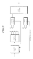
- FIG. 10 is a block diagram of a MIMO system implementing a power allocation and a precoding for increasing an SINR.
- the transmitting apparatus includes the same precoder 810 and power controller 816 as those of FIG. 8
- two receiving apparatuses include the same post-decoders 812 and 814 as those of FIG. 8 and channel estimators 818 and 820.
- a precoding of the precoder 810 corresponds to transforming a transmission type of a signal.
- a precoding wireless communication system does not directly output transmission signals through antennas in a one to one correspondence manner, but transmits signals through virtual antennas in such a manner that operation processed values of operation processed signals in advance are transmitted through antennas or transmits signals through virtual channels generated by a precoding.
- power of signals transmitted through the virtual channels corresponds to transmission power of each actual signal.
- the precoder 810 precodes a source bit stream by multiplexing a precoding matrix, and provides the power controller 816 with virtual channel information according to estimates of the precoding matrix and the channel estimation.
- the power controller 816 receives inputs of the precoded value and the virtual channel information and allocates power for each stream to obtain a maximum reception SINR or a reception SINR approximated to the maximum reception SINR based on the virtual channel information.
- the channel estimators 818 and 820 of the receiving apparatus estimate channel information by using signals received through two or more antennas, and transmit the estimated channel information to the transmitting apparatus.
- the precoder 810 of the transmitting apparatus provides the power controller 816 with the channel information received from the channel estimators 818 and 820 and the virtual channel information generated by multiplexing the precoding matrix.
- the power controller 816 allocates power for each stream to obtain the maximum reception SINR or the reception SINR approximated to the maximum reception SINR based on the virtual channel information provided from the precoder 810.
- the transmitting apparatus transmits a signal for each stream through multiple antennas according to power allocated for each stream from the power controller 816.
- the channel estimators 818 and 820 of the receiving apparatus receives signals transmitted through multiple antennas for each stream according to power allocated for each stream to obtain the reception SINR of the power controller 816, so that the channel estimators 818 and 820 receive a signal of a maximum SINR or an SINR approximated to the maximum SINR.
- the post-decoders 812 and 814 multiplex signals received through antennas by a specific matrix to decode them to final reception signals.
- a power allocation is performed in consideration of characteristics of a virtual antenna and a virtual channel, and through the approaches, the power allocation may be performed in consideration of capabilities of all precoders 810 available in an actual MIMO system.
- the channel estimators 818 and 820 of the receiving apparatus acquire channel information or channel state information to transmit it to the transmitting apparatus.
- the transmitting apparatus When the transmitting apparatus is aware of channel information or channel state information since the transmitting apparatus receives feedback information, that is, the channel information or the channel state information from the channel estimators 818 and 820 of the receiving apparatus (in a case of a closed-loop MIMO), the transmitting apparatus allocates power for each stream based on information about the virtual channel H' of the transmitting apparatus. In addition, when the transmitting apparatus is also aware of information on the post-decoders 812 and 814 used in the receiving apparatus, the transmitting apparatus can allocate power for each stream based on information about the virtual channel H" reflecting a post decoding matrix.
- a power allocation or a power control has a concept of individually controlling outputs of transmission antennas.
- the number of signals desired to be simultaneously transmitted is 2 and the number of transmission antennas is 2
- x 1 s 1 , so it is possible to control each output size of antennas and control reception power of each signal.
- controlling each of outputs of antennas x 0 and x 1 is useless, but, instead, transmission power of signals s 0 and s 1 are controlled and allocated by controlling outputs of virtual antennas represented by [0.7 0.3] T and [0.3 0.7] T .
- the transmitting apparatus receives channel information or channel state information from the channel estimators 818 and 820 of the receiving apparatus, calculates a reception SINR of the receiving apparatus based on information about virtual channels ( H',H" ) of the transmitting apparatus generated by multiplexing the channel information by a precoding matrix, and allocates power for each stream such that an optimal reception SINR can be obtained.
- the reception SINR is modeled as below.
- SINR j 0 ⁇ s 0 2 j 1 ⁇ s 1 + j 2 ⁇ s 2 2 + ⁇ 2
- j n denotes a propagation path gain of s n
- ⁇ 2 denotes an intensity of noise
- the channel has quasi-static characteristics.
- a reception SINR of which reception capability is expressed by an average SINR within a quasi-static section is defined as formula (2) below.
- j n denotes a square of a propagation path gain of a signal s n
- ⁇ n denotes transmission power of a signal s n .
- J ⁇ 11 ⁇ 1 ⁇ N ⁇ ⁇ M ⁇ 1 ⁇ NN
- a diagonal element of R JP is reception power of each signal
- a reception SINR for a signal s n of a reception antenna n is defined by formula (5) when the reception antenna n receives the signal s n desired to be received.
- r n,n in the numerator denotes a signal intensity of a signal s n
- r n,r in the denominator denotes an interference intensity of the signal s n
- ⁇ 2 in the denominator denotes a noise intensity
- an SINR is defined by a sum of power of signals desired to be received and a sum of power of signals not desired to be received. That is, as shown FIGs. 8 and 10 , when signals which a receiving apparatus 1 desires to receive, are x 1 and x 2 , and signals which a receiving apparatus 2 desires to receive, are x 3 and x 4 , reception SINRs of the receiving apparatuses 1 and 2 are defined by formulas (6) and (7).
- the numerator denotes a sum of signal intensities of signals x 1 and x 2 , which two antennas (antennas 1 and 2) of the receiving apparatus 1 desire to receive, ⁇ 2 in the denominator denotes a noise intensity, and the remaining elements in the denominator denote a sum of signal intensities of x 3 and x 4 , which are interference signals which two antennas (antennas 1 and 2) of the receiving apparatus 1 have received but do not desire to receive.
- the numerator denotes a sum of signals intensities of signals x 3 and x 4 , which two antennas (antennas 3 and 4) of the receiving apparatus 2 desire to receive
- ⁇ 2 in the denominator denotes a noise intensity
- the remaining elements in the denominator denote a sum of signal intensities of x 1 and x 2 , which are interference signals which two antennas (antennas 3 and 4) of the receiving apparatus 2 have received but do not desire to receive.
- Formulas (6) and (7) have a plurality of poles and peaks according to channel states, so that it is difficult to find a closed form solution, but it is possible to find optimal power P through an iterative process.
- An iterative method is generally based on the water-filling method.
- an interference matrix I is defined by formula (8) below to express a total SINR as a matrix formula.
- I c 11 ⁇ ⁇ 11 ⁇ c N ⁇ 1 ⁇ ⁇ N ⁇ 1 ⁇ ⁇ ⁇ c 1 ⁇ M ⁇ ⁇ 1 ⁇ M ⁇ c NM ⁇ ⁇ NM
- c ij is indicated by "0" when receptions of the same signals to a reception antenna i of the receiving apparatus and a transmitting antenna j of the transmitting apparatus do not negatively affect the capability of the receiving apparatus, and otherwise, c ij is indicated by "1".
- Power of an interference signal in a receiving antenna-n is defined as an nth row of IxP or a product of an nth row of I and P through the settings.
- a matrix R indicating reception power of each stream is determined by the number of used reception antennas.
- R ⁇ 11 + 1 - c 12 ⁇ ⁇ 12 0 0 0 0 ⁇ 22 + 1 - c 21 ⁇ ⁇ 21 0 0 0 0 ⁇ 33 + 1 - c 34 ⁇ ⁇ 34 0 0 0 0 ⁇ 44 + 1 - c 43 ⁇ ⁇ 44
- FIG. 11 is a flowchart of a power allocation method according to embodiments of the present invention.
- the change in each signal SINR is predicted according to a power allocation S1114.
- the change in each signal SINR is predicted.
- the process is repeated until available power remains, and a power allocation is terminated when the available power does not remain.
- power corresponding to a reception SINR is allocated S1116. That is, a solution of formula (10) is calculated while sequentially increasing P 1 to P N by the variance ⁇ until the available power remains, and power of each antenna is allocated by P 1 to P N right before a state where the available power does not remain.
- the power controller 816 disposed before/after the resource element mapper 218 of FIG. 3 controls such that signals are transmitted through multiple antennas with power for each stream of multiple antennas allocated through the above process.
- multiple antennas broadcast signals (electromagnetic waves) to the air by power allocated from the power controller 816, that is, intensities of the signals.
- power is allocated to each stream in such a manner that a maximum reception SINR or a reception SINR approximated to the maximum reception SINR can be obtained in a state where there are interferences between streams, so that throughput may be increased and a transmission capacity may be maximized.
- power for each stream is allocated such that a reception SINR of one or more receiving apparatuses can be maximized based on virtual channel information calculated by a precoding matrix and channel information provided by the receiving apparatus
- power for each stream may be allocated such that reception power or a reception SNR as well as the reception SINR can be maximized.
- maximum reception power or a maximum reception SNR is obtained based on the virtual channel information calculated by the precoding matrix and the channel information.
Landscapes
- Engineering & Computer Science (AREA)
- Computer Networks & Wireless Communication (AREA)
- Signal Processing (AREA)
- Quality & Reliability (AREA)
- Power Engineering (AREA)
- Radio Transmission System (AREA)
- Mobile Radio Communication Systems (AREA)
- Transmitters (AREA)
Applications Claiming Priority (2)
| Application Number | Priority Date | Filing Date | Title |
|---|---|---|---|
| KR1020090056706A KR20100138260A (ko) | 2009-06-24 | 2009-06-24 | 무선통신 시스템에서 전력 할당방법 및 그 장치, 이를 적용한 송수신장치 신호전송 |
| PCT/KR2010/004075 WO2010151046A2 (ko) | 2009-06-24 | 2010-06-23 | 무선통신 시스템에서 전력 할당방법 및 그 장치, 이를 적용한 송수신장치 신호전송 |
Publications (1)
| Publication Number | Publication Date |
|---|---|
| EP2448138A2 true EP2448138A2 (de) | 2012-05-02 |
Family
ID=43387044
Family Applications (1)
| Application Number | Title | Priority Date | Filing Date |
|---|---|---|---|
| EP10792328A Withdrawn EP2448138A2 (de) | 2009-06-24 | 2010-06-23 | Stromzuweisungsverfahren für drahtloses kommunikationssystem, vorrichtung dafür und sender-empfängervorrichtung, die diese form der signalübertragung verwendet |
Country Status (6)
| Country | Link |
|---|---|
| US (1) | US20120093253A1 (de) |
| EP (1) | EP2448138A2 (de) |
| JP (1) | JP2012531796A (de) |
| KR (1) | KR20100138260A (de) |
| CN (1) | CN102549936A (de) |
| WO (1) | WO2010151046A2 (de) |
Cited By (2)
| Publication number | Priority date | Publication date | Assignee | Title |
|---|---|---|---|---|
| CN104734819A (zh) * | 2013-12-20 | 2015-06-24 | 西安电子科技大学 | 基于干扰抑制与容量提升的多小区干扰对齐算法 |
| CN105379131A (zh) * | 2014-03-11 | 2016-03-02 | 华为技术有限公司 | 一种信号处理方法、装置 |
Families Citing this family (16)
| Publication number | Priority date | Publication date | Assignee | Title |
|---|---|---|---|---|
| KR20120009649A (ko) * | 2010-07-20 | 2012-02-02 | 삼성전자주식회사 | 다중 사용자 다중안테나 시스템에서 채널 직교화를 이용한 선처리 방법 및 장치 |
| CN102340341A (zh) * | 2011-07-08 | 2012-02-01 | 中兴通讯股份有限公司 | 一种上行系统中多天线的信号处理方法及装置 |
| EP2547022A1 (de) * | 2011-07-13 | 2013-01-16 | Intel Mobile Communications Technology Dresden GmbH | Verfahren und Vorrichtung zur Bestimmung von Kanalstatusinformationen |
| KR20130104369A (ko) | 2012-03-13 | 2013-09-25 | 삼성전자주식회사 | 협력 전송 기반의 다중 안테나 시스템에서의 전송 파워 결정 방법 |
| JP5849851B2 (ja) * | 2012-04-26 | 2016-02-03 | 富士通株式会社 | 無線端末装置、無線通信システム及び無線端末装置制御方法 |
| US9154208B2 (en) * | 2012-06-13 | 2015-10-06 | Alcatel Lucent | System and method of wireless fixed access using a multiple antenna array |
| CN103701511B (zh) * | 2013-12-06 | 2017-03-29 | 武汉邮电科学研究院 | 一种lte 系统下行mimo 技术的查表实现系统及方法 |
| JP6495279B2 (ja) * | 2014-07-18 | 2019-04-03 | シャープ株式会社 | 端末装置、基地局装置、および通信方法 |
| EP3327983A1 (de) * | 2014-09-11 | 2018-05-30 | NTT DoCoMo, Inc. | Basis station, benutzergerät und radiokommunikationssystem |
| WO2016124876A1 (en) * | 2015-02-04 | 2016-08-11 | Toshiba Research Europe Limited | Methods and systems for transmitting information across a mimo channel from a transmitter to a receiver |
| US10411771B2 (en) * | 2015-03-30 | 2019-09-10 | Kabushiki Kaisha Toshiba | Wireless communication methods and apparatus |
| WO2017003963A1 (en) * | 2015-06-28 | 2017-01-05 | Ping Liang | Power allocation and precoding matrix computation method in a wireless communication system |
| JP7341980B2 (ja) * | 2017-08-15 | 2023-09-11 | フラウンホッファー-ゲゼルシャフト ツァ フェルダールング デァ アンゲヴァンテン フォアシュンク エー.ファオ | 無線ネットワークおよび装置 |
| WO2019158193A1 (en) * | 2018-02-14 | 2019-08-22 | Telefonaktiebolaget Lm Ericsson (Publ) | Link adaptation correction for low latency mu-mimo |
| US11159208B1 (en) | 2020-07-15 | 2021-10-26 | Samsung Electronics Co., Ltd | Optimal precoder method and apparatus with equal power allocation |
| CN115720102B (zh) * | 2021-08-24 | 2024-11-22 | 上海华为技术有限公司 | 一种无线通信方法、相关装置及设备 |
Family Cites Families (7)
| Publication number | Priority date | Publication date | Assignee | Title |
|---|---|---|---|---|
| KR20050089698A (ko) * | 2004-03-05 | 2005-09-08 | 삼성전자주식회사 | 어레이 안테나를 갖는 이동통신시스템에서 데이터 송/수신장치 및 방법 |
| RU2007144717A (ru) * | 2005-06-01 | 2009-06-10 | Мацусита Электрик Индастриал Ко., Лтд. (Jp) | Передающее устройство, приемное устройство и способ управления мощностью передачи |
| CN1893342B (zh) * | 2005-07-05 | 2010-06-09 | 上海原动力通信科技有限公司 | 多载波hsdpa的业务传输信道编码方法和编码装置 |
| US20070165738A1 (en) * | 2005-10-27 | 2007-07-19 | Barriac Gwendolyn D | Method and apparatus for pre-coding for a mimo system |
| CN101340218A (zh) * | 2007-07-04 | 2009-01-07 | 华为技术有限公司 | 多输入多输出系统中通信方法及装置 |
| CN101252418A (zh) * | 2008-04-01 | 2008-08-27 | 东南大学 | 多天线传输系统中利用信道统计信息的自适应传输方法 |
| US20100067512A1 (en) * | 2008-09-17 | 2010-03-18 | Samsung Electronics Co., Ltd. | Uplink transmit diversity schemes with 4 antenna ports |
-
2009
- 2009-06-24 KR KR1020090056706A patent/KR20100138260A/ko not_active Withdrawn
-
2010
- 2010-06-23 JP JP2012517381A patent/JP2012531796A/ja not_active Withdrawn
- 2010-06-23 US US13/380,461 patent/US20120093253A1/en not_active Abandoned
- 2010-06-23 EP EP10792328A patent/EP2448138A2/de not_active Withdrawn
- 2010-06-23 WO PCT/KR2010/004075 patent/WO2010151046A2/ko not_active Ceased
- 2010-06-23 CN CN2010800371637A patent/CN102549936A/zh active Pending
Non-Patent Citations (1)
| Title |
|---|
| See references of WO2010151046A2 * |
Cited By (5)
| Publication number | Priority date | Publication date | Assignee | Title |
|---|---|---|---|---|
| CN104734819A (zh) * | 2013-12-20 | 2015-06-24 | 西安电子科技大学 | 基于干扰抑制与容量提升的多小区干扰对齐算法 |
| CN104734819B (zh) * | 2013-12-20 | 2018-08-17 | 西安电子科技大学 | 基于干扰抑制与容量提升的多小区干扰对齐算法 |
| CN105379131A (zh) * | 2014-03-11 | 2016-03-02 | 华为技术有限公司 | 一种信号处理方法、装置 |
| EP3110016A4 (de) * | 2014-03-11 | 2017-03-29 | Huawei Technologies Co., Ltd. | Signalverarbeitungsverfahren und -vorrichtung |
| US9813092B2 (en) | 2014-03-11 | 2017-11-07 | Huawei Technologies Co., Ltd. | Signal processing method and apparatus |
Also Published As
| Publication number | Publication date |
|---|---|
| WO2010151046A3 (ko) | 2011-03-31 |
| CN102549936A (zh) | 2012-07-04 |
| JP2012531796A (ja) | 2012-12-10 |
| KR20100138260A (ko) | 2010-12-31 |
| WO2010151046A2 (ko) | 2010-12-29 |
| US20120093253A1 (en) | 2012-04-19 |
Similar Documents
| Publication | Publication Date | Title |
|---|---|---|
| EP2448138A2 (de) | Stromzuweisungsverfahren für drahtloses kommunikationssystem, vorrichtung dafür und sender-empfängervorrichtung, die diese form der signalübertragung verwendet | |
| US11005627B2 (en) | Apparatus and method for transmitting a reference signal in a wireless communication system | |
| EP2490345B1 (de) | Verfahren und vorrichtung zur modusumschaltung zwischen einem mehrzellen-koordinierten kommunikationsmodus und einem einzelzellen-mimo-kommunikationsmodus | |
| CN109565311B (zh) | 在无线通信系统中的上行链路发送/接收的方法及其装置 | |
| EP2424123B1 (de) | Vorrichtung und verfahren zur übertragung eines referenzsignals in einem funkkommunikationssystem | |
| Boccardi et al. | Multiple-antenna techniques in LTE-advanced | |
| EP2996258B1 (de) | Verfahren zur berichterstattung von kanalstatusinformationen für dreidimensionale strahlformung in einem drahtloskommunikationssystem und vorrichtung dafür | |
| US8964591B2 (en) | Method and device for transmitting/receiving channel state information in a wireless communication system | |
| US8989062B2 (en) | Method and arrangement in a wireless communication system | |
| EP2961081B1 (de) | Verfahren zur übertragung eines signals in einem drahtlosen kommunikationssystem und vorrichtung dafür | |
| KR20100109387A (ko) | 무선 통신 시스템에서 신호 전송 방법 및 장치 | |
| US20190341974A1 (en) | Method for transmitting plurality of beamformed reference signals for open-loop mimo transmission in wireless communication system and apparatus therefor | |
| WO2016111427A1 (ko) | 무선 통신 시스템에서 안테나의 편파 특성을 이용한 채널 상태 정보의 구성 방법 및 이를 위한 장치 | |
| KR20160007495A (ko) | 무선 통신 시스템에서 채널 상태 정보를 보고하는 방법 및 이를 위한 장치 | |
| EP3306830A1 (de) | Verfahren und vorrichtung zum senden und empfangen von kanalstatusinformationen in einem kommunikationssystem zwischen fahrzeugen | |
| WO2017204436A1 (ko) | 분산 안테나 통신 시스템에서 상향링크 신호를 송신하는 방법 및 이를 위한 장치 | |
| WO2018026073A1 (ko) | 무선 통신 시스템에서 빔포밍된 참조 신호에 기반하여 3 차원 mimo를 위한 피드백 정보를 송신하는 방법 및 이를 위한 장치 | |
| EP2753002B1 (de) | Vorrichtung und verfahren zur übertragung von kanalstatusinformationen in einem drahtlosen kommunikationssystem | |
| US10608724B2 (en) | Method for reporting CSI in wireless communication system and device for same | |
| US20200052862A1 (en) | Method for reporting channel quality information in tdd type wireless communication system, and device therefor | |
| Sawahashi et al. | CSI reference signal multiplexing using carrier frequency swapping for fdd high-order MIMO SDM | |
| Kaltenberger et al. | Experimental analysis of network-aided interference-aware receiver for LTE MU-MIMO | |
| Hsu et al. | Power allocation for downlink path-based precoding in multiuser FDD massive MIMO systems without CSI feedback | |
| Frank | Advanced transmission schemes for the 4th generation of mobile communication systems | |
| Xiao et al. | Mutual Information Based Packet Scheduling for Linearly Precoded Multiuser MIMO Systems |
Legal Events
| Date | Code | Title | Description |
|---|---|---|---|
| PUAI | Public reference made under article 153(3) epc to a published international application that has entered the european phase |
Free format text: ORIGINAL CODE: 0009012 |
|
| 17P | Request for examination filed |
Effective date: 20120119 |
|
| AK | Designated contracting states |
Kind code of ref document: A2 Designated state(s): AL AT BE BG CH CY CZ DE DK EE ES FI FR GB GR HR HU IE IS IT LI LT LU LV MC MK MT NL NO PL PT RO SE SI SK SM TR |
|
| DAX | Request for extension of the european patent (deleted) | ||
| STAA | Information on the status of an ep patent application or granted ep patent |
Free format text: STATUS: THE APPLICATION HAS BEEN WITHDRAWN |
|
| 18W | Application withdrawn |
Effective date: 20141121 |