EP2448090A1 - Stator of vehicle ac generator and method for manufacturing the same - Google Patents
Stator of vehicle ac generator and method for manufacturing the same Download PDFInfo
- Publication number
- EP2448090A1 EP2448090A1 EP09846487A EP09846487A EP2448090A1 EP 2448090 A1 EP2448090 A1 EP 2448090A1 EP 09846487 A EP09846487 A EP 09846487A EP 09846487 A EP09846487 A EP 09846487A EP 2448090 A1 EP2448090 A1 EP 2448090A1
- Authority
- EP
- European Patent Office
- Prior art keywords
- stator
- varnish
- tooth
- vehicle
- inner diameter
- Prior art date
- Legal status (The legal status is an assumption and is not a legal conclusion. Google has not performed a legal analysis and makes no representation as to the accuracy of the status listed.)
- Granted
Links
Images

Classifications
-
- H—ELECTRICITY
- H02—GENERATION; CONVERSION OR DISTRIBUTION OF ELECTRIC POWER
- H02K—DYNAMO-ELECTRIC MACHINES
- H02K1/00—Details of the magnetic circuit
- H02K1/04—Details of the magnetic circuit characterised by the material used for insulating the magnetic circuit or parts thereof
-
- H—ELECTRICITY
- H02—GENERATION; CONVERSION OR DISTRIBUTION OF ELECTRIC POWER
- H02K—DYNAMO-ELECTRIC MACHINES
- H02K15/00—Processes or apparatus specially adapted for manufacturing, assembling, maintaining or repairing of dynamo-electric machines
- H02K15/12—Impregnating, moulding insulation, heating or drying of windings, stators, rotors or machines
-
- H—ELECTRICITY
- H02—GENERATION; CONVERSION OR DISTRIBUTION OF ELECTRIC POWER
- H02K—DYNAMO-ELECTRIC MACHINES
- H02K3/00—Details of windings
- H02K3/44—Protection against moisture or chemical attack; Windings specially adapted for operation in liquid or gas
-
- Y—GENERAL TAGGING OF NEW TECHNOLOGICAL DEVELOPMENTS; GENERAL TAGGING OF CROSS-SECTIONAL TECHNOLOGIES SPANNING OVER SEVERAL SECTIONS OF THE IPC; TECHNICAL SUBJECTS COVERED BY FORMER USPC CROSS-REFERENCE ART COLLECTIONS [XRACs] AND DIGESTS
- Y10—TECHNICAL SUBJECTS COVERED BY FORMER USPC
- Y10T—TECHNICAL SUBJECTS COVERED BY FORMER US CLASSIFICATION
- Y10T29/00—Metal working
- Y10T29/49—Method of mechanical manufacture
- Y10T29/49002—Electrical device making
- Y10T29/49009—Dynamoelectric machine
Definitions
- the present invention relates to a stator of a vehicle AC generator to be installed on a vehicle or the like and a method for manufacturing the same.
- Patent Document 1 discloses that a continuous film with no unevenness can be formed with a sufficient film thickness even in a case where a coating film is insufficient when impregnation coating with a brush or spray coating is performed, the case including the space between laminates.
- Patent Document 2 discloses one in which irregularities between strip-shaped bodies in an inner diameter direction of a stator core are eliminated to avoid inward protrusion of edges of the strip-shaped bodies, this makes it possible to perform coating for uniform anti-rust to prevent the occurrence of the locked state of rotation due to rust generated between a rotor and a stator and to eventually prevent performance defects, and the amount of coating to be used for anti-rust of the inner periphery of the stator can be reduced.
- Patent Document 1 Japanese Unexamined Patent Publication No. Hl-2'78242
- the tooth portion needs to be grounded as a cathode in order to form the electrodeposition coating film; but, this results in a problem in that the tooth portion is almost covered after a stator coil is wound and there is little space for grounding. More particularly, in a stator provided with slots and teeth whose number is 1.5 times or 2 times as much as the number of conventional slots and teeth, it is in a state where the width of the tooth is narrower and an obtainable space is little more and more. Furthermore, masking needs to be individually performed for a portion where resin coating is not needed; not only work is troublesome throughout the whole, but also much investment in facilities is needed; and thus, it is not suitable for mass production.
- This invention has been made to solve the problem as described above, and an object of the present invention is to provide a stator of a vehicle AC generator and a method for manufacturing the same, in which uniformization of a coating film on the inner diameter end surface of a tooth facing a rotor is easy, anti-rust properties are excellent, process is simple, much investment in facilities is not needed, and manufacture can be performed inexpensively.
- a stator of a vehicle AC generator including: a case which incorporates or removably supports constituent components; a shaft rotatably supported on the case; a rotor which has pole cores secured on the shaft and a field winding placed in the pole cores; a stator which includes a stator core located on the periphery of the rotor and to be held in sandwiched relation in the case, and a stator winding disposed in the stator core; a rectifier which rectifies AC electromotive force generated in the stator winding to DC; and a voltage regulator which restricts generated electric power to a specified value.
- the stator core is formed by laminating thin steel sheets, the stator core being provided with a plurality of slot portions which accommodate the stator winding and tooth portions which define adjacent ones of the slot portions; and the stator winding is disposed in the slot portions to constitute the stator.
- the stator core is filled with varnish between the laminates of each tooth at least in an inner diameter end surface region which faces said rotor, and is coated with epoxy resin varnish on the tooth surface of the inner diameter end surface region to form an anti-rust film.
- the method includes a step of filling the varnish between the laminates of each tooth; and a step of trickling the varnish into the stator winding to be disposed in the core slot portions, the filling step being performed at the same time as the trickling step.
- a stator of a vehicle AC generator and a method for manufacturing the same, in which uniformization of a resin film on an inner diameter end surface of a tooth facing a rotor is easy, anti-rust properties are excellent, process is simple, much investment in facilities is not needed, and manufacture can be performed inexpensively.
- Fig. 1 is a schematic sectional view of a vehicle AC generator according to Embodiment 1 of the present invention
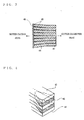
- Fig. 2 is a schematic perspective view of a stator core according to Embodiment 1 of the present invention
- Fig. 1 is a schematic sectional view of a vehicle.AC generator according to Embodiment 1 of the present invention
- Fig. 2 is a perspective view in which only a core portion of a stator shown in Fig. 1 is taken out.
- Fig. 1 the whole structure of the vehicle AC generator will be described with reference to Fig. 1 .
- Fig. 1 the whole structure of the vehicle AC generator will be described with reference to Fig. 1 .
- a vehicle AC generator 1 incudes a case 2 which surrounds and removably supports constituent components in the inside thereof, a shaft 33 rotatably supported on the case 2, a rotor 3 secured on the shaft 33 and rotatably disposed in the case 2, cooling fans 35 secured on the axial ends of the rotor 3, a stator 4 held by the case 2 so as to surround the rotor 3, a pair of slip rings 5 which are secured on a rear side end portion of the shaft 33 and supply a field current to a field winding 34 of the rotor 3, a brush 6, a rectifier 7 which is electrically connected to the stator 4 and rectifies AC generated by the stator 4 to DC, and a voltage regulator 8 which regulates the magnitude of AC voltage generated by the stator 4.
- the rotor 3 includes a field, winding 34 which generates magnetic flux by flowing through the field current, and pole cores 31, 32 which are provided so as to enclose the field winding 34 to form magnetic poles by the magnetic flux.
- the stator 4 includes a stator core 42 (to be described later), and a stator winding 41 which is wound around the stator core 42 and generates AC by a change in magnetic flux from the field winding 34 with the rotation of the rotor 3.
- the stator 4 is disposed so as to surround the rotor 3 and is attached to the case 2.
- Fig. 2 is the perspective view showing the stator core 42 of the stator 4; and the stator core 42 is formed by overlapping a predetermined number of thin steel sheets with a plurality of slot portions 43 provided in the inner diameter side thereof, the slot portions accommodating the stator winding 41.
- Each tooth portion 44 is formed between the slots.
- Fig. 3 that is an axial sectional view of the tooth region, the laminated steel sheets are separated between the laminates respectively on the inner diameter side (the side facing the rotor, i.e., the rotor-facing side) of the stator core 42; and the separated part is filled with varnish 45.
- a state where the varnish 45 is filled is a state where the end surfaces 44 of the core 42 and the varnish layers 45 constitute a series of inner diameter end surfaces.
- Varnish to be used is Tris-(2-hydroxyethyl) isocyanurate (THEIC) denatured unsaturated polyester, which is varnish to be conventionally filled in coil ends of the stator winding.
- TEEIC Tris-(2-hydroxyethyl) isocyanurate
- Varnish is filled in the space between laminated cores at the same time as a varnish trickling step in which the varnish is trickled into the stator winding; and accordingly, process is simple, additional facilities are not needed, and the varnish can be filled between the laminated cores.
- the varnish 45 is trickled to the stator winding 41 to impregnate the varnish 45 in the winding while rotating the stator 4 in which the stator winding 41 is disposed.
- a nozzle for trickling varnish is moved toward the tooth sidle; and accordingly, the varnish can be radially trickled between the laminates of the tooth 44.
- the filling is performed after the stator core and the stator winding are heated to high temperature; and therefore, if the varnish is trickled, the varnish lowers in viscosity immediately to be lubricious and the varnish is penetrated into the stator winding and the space between the laminated cores, and the varnish is provided being extended in a tongue shape toward the base between the laminates of tooth portions.
- epoxy resin varnish (specially denatured epoxy resin paint) 46 is spray-coated to the tooth surface of the core inner diameter side (the rotor-facing side) ; and accordingly, an anti-rust film with uniform film thickness can be formed as shown in Fig. 6 .
- the separation between the laminates of the tooth region can be obtained by controlling axial dimension of only the outer diameter side after the thin steel sheets are laminated.
- the outer side is controlled; and accordingly, the inner diameter side (the rotor-facing side) end surface tends to be axially expanded.
- the varnish to be filled in the space between the laminated cores is different from the varnish to be applied to the inner diameter end surface of the tooth; however, these varnishes may be the same varnish. What matters is, as long as varnish is preliminarily filled in the space between the laminated cores to fill in the space and then the varnish is applied to the inner diameter end surface of the tooth, it is easy to form a uniform film on the inner diameter end surface of the tooth and the amount of the varnish can be reduced.
- Embodiment 1 of the present invention a defect in which varnish is drawn in the spaces of the side surfaces of the coating surface is eliminated and a product which reliably ensures the paint thickness on the tooth surface can be obtained, the defect being occurred in the case of using epoxy resin varnish which adopts spray coating because of high in anti-rust properties but lower in penetration properties than varnish. Accordingly, even when salty water or the like sticks at the time of installing on a vehicle, the epoxy resin varnish with high anti-rust properties covers the inner diameter side surface of the stator tooth with sufficient film thickness; and therefore, this avoids to generate rust between the inner diameter side surface of the stator tooth and the rotor to prevent from locking rotation that may cause a performance defect.
- the varnish is filled in the space between the laminated cores; and accordingly, air in the space is eliminated, thermal conductivity is more enhanced than a state where only laminated because of via the varnish, and heat dissipation properties of the laminated cores are increased and the reduction effect of temperature can be obtained.
- varnish that is, a resin film
- damper function can be obtained and electromagnetic oscillation peculiar to a generator can be attenuated.
- Fig. 7 shows a sectional view of a stator core according to Embodiment 2 of the present invention.
- Fig. 3 of the aforementioned Embodiment 1 there has been exemplified the case where the varnish 45 is filled in only the space between laminates of the cores; however, in Embodiment 2, viscosity of varnish or a coated state is selected and accordingly varnish 45 is filled in the space between laminates of teeth and coated to the end surface of the core inner diameter side.
- Embodiment 2 as compared to Embodiment 1, the amount of coating of subsequently provided epoxy resin varnish is small and there is an advantage in cost that is expected to be improved.
- Fig. 8 shows an axial sectional view of a stator core according to Embodiment 3 of the present invention.
- Embodiment 1 and Embodiment 2 there has been described the case where the space between the laminates is configured so that only the end side of the tooth (that is, the side of the rotor-facing surface) is axially expanded; however, in Embodiment 3, as shown in Fig. 8 , a space is configured in almost the whole portion other than an outermost diameter region of a stator core.
- varnish is filled in a slot depth direction, that is, toward a radial direction from the inner diameter end surface side to the outer diameter side of the core, at least by a length not less than the height of a stator winding in the slot, the stator winding being disposed in the slot portions.
- the varnish is also expanded from the side surface in the radial direction of the tooth to the stator winding disposed in the slot; and therefore, it is possible to obtain a product having a better state as compared to a state where the varnish is filled into the winding portion in the slot, the filling of the varnish into the winding portion being performed by capillary phenomenon from winding regions protruded from slot axial end portions.
- Fig. 9 shows an axial sectional view of a stator core according to Embodiment 4 of the present invention.
- Embodiment 4 uses one in which the sheet thickness of thin steel sheets which form a tooth portion of a stator core 42 is not uniform, but the sheet thickness of the inner diameter side of the tooth portion is thinner than that of other portion (a central portion or an outline portion).
- the present invention is not limited to such laminated configuration in which the sheet thickness is uniform, but the configuration in which the inner diameter side of the tooth portion becomes thinner is also applicable and similar effects to Embodiment 1 can also be obtained in Embodiment 4.
- the present invention is applied to an AC generator to be installed on a vehicle.
Landscapes
- Engineering & Computer Science (AREA)
- Power Engineering (AREA)
- Iron Core Of Rotating Electric Machines (AREA)
- Manufacture Of Motors, Generators (AREA)
Abstract
Description
- The present invention relates to a stator of a vehicle AC generator to be installed on a vehicle or the like and a method for manufacturing the same.
- As a conventional stator for use in a vehicle AC generator, in a stator core formed by a plurality of laminated cores having tooth portions and slot portions, there is one in which an electrodeposition coating film made of insulation resign is formed on a rotor-facing surface (a surface facing a rotor) in the tooth portion (for example, see Patent Document 1).
Patent Document 1 discloses that a continuous film with no unevenness can be formed with a sufficient film thickness even in a case where a coating film is insufficient when impregnation coating with a brush or spray coating is performed, the case including the space between laminates. - Furthermore, as other conventional example, for example.
Patent Document 2 discloses one in which irregularities between strip-shaped bodies in an inner diameter direction of a stator core are eliminated to avoid inward protrusion of edges of the strip-shaped bodies, this makes it possible to perform coating for uniform anti-rust to prevent the occurrence of the locked state of rotation due to rust generated between a rotor and a stator and to eventually prevent performance defects, and the amount of coating to be used for anti-rust of the inner periphery of the stator can be reduced. - Patent Document 1: Japanese Unexamined Patent Publication No.
Hl-2'78242 - Patent Document 2: Japanese Unexamined Patent Publication No.
2006-345671 - . However, in the conventional stator disclosed in
Patent Document 1, the tooth portion needs to be grounded as a cathode in order to form the electrodeposition coating film; but, this results in a problem in that the tooth portion is almost covered after a stator coil is wound and there is little space for grounding.
More particularly, in a stator provided with slots and teeth whose number is 1.5 times or 2 times as much as the number of conventional slots and teeth, it is in a state where the width of the tooth is narrower and an obtainable space is little more and more. Furthermore, masking needs to be individually performed for a portion where resin coating is not needed; not only work is troublesome throughout the whole, but also much investment in facilities is needed; and thus, it is not suitable for mass production. - Furthermore, in other conventional example disclosed in
Patent Document 2, only the irregularities between the strip-shaped bodies in the inner diameter direction of the stator core are eliminated (perfect circle dimension) , but any countermeasure is not taken against the space between the laminates.
In the case of coating the inner peripheral surface of the stator in which a space exists between the laminates, for example, when the inner peripheral surface is coated with paint that is high in anti-rust properties but is low in penetration properties, there is a problem in that paint is unnecessarily drawn between the laminates due to direct advance properties of sprayed spray and it is difficult to ensure the required coating thickness of the cylindrical inner peripheral surface. - This invention has been made to solve the problem as described above, and an object of the present invention is to provide a stator of a vehicle AC generator and a method for manufacturing the same, in which uniformization of a coating film on the inner diameter end surface of a tooth facing a rotor is easy, anti-rust properties are excellent, process is simple, much investment in facilities is not needed, and manufacture can be performed inexpensively.
- According to the present invention, there is provided a stator of a vehicle AC generator, the vehicle AC generator including: a case which incorporates or removably supports constituent components; a shaft rotatably supported on the case; a rotor which has pole cores secured on the shaft and a field winding placed in the pole cores; a stator which includes a stator core located on the periphery of the rotor and to be held in sandwiched relation in the case, and a stator winding disposed in the stator core; a rectifier which rectifies AC electromotive force generated in the stator winding to DC; and a voltage regulator which restricts generated electric power to a specified value. The stator core is formed by laminating thin steel sheets, the stator core being provided with a plurality of slot portions which accommodate the stator winding and tooth portions which define adjacent ones of the slot portions; and the stator winding is disposed in the slot portions to constitute the stator. The stator core is filled with varnish between the laminates of each tooth at least in an inner diameter end surface region which faces said rotor, and is coated with epoxy resin varnish on the tooth surface of the inner diameter end surface region to form an anti-rust film.
- Furthermore, in a method for manufacturing the stator of the vehicle AC generator, the method includes a step of filling the varnish between the laminates of each tooth; and a step of trickling the varnish into the stator winding to be disposed in the core slot portions, the filling step being performed at the same time as the trickling step.
- According to the present invention, it is possible to obtain a stator of a vehicle AC generator and a method for manufacturing the same, in which uniformization of a resin film on an inner diameter end surface of a tooth facing a rotor is easy, anti-rust properties are excellent, process is simple, much investment in facilities is not needed, and manufacture can be performed inexpensively.
- The foregoing and other object, features, and advantages of the present invention will become more apparent from the following detailed description of embodiments and description shown in the accompanying drawings.
-
Fig. 1 is a schematic sectional view of a vehicle AC generator according toEmbodiment 1 of the present invention;Fig. 2 is a schematic perspective view of a stator core according toEmbodiment 1 of the present invention; -
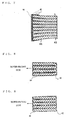
Fig. 3 is an axial sectional view of a stator core shown inFig. 2 ; -
Fig. 4 is a schematic perspective view in which the stator core shown inFig. 2 is seen from the end of a tooth prior to spray coating; -
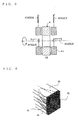
Fig. 5 is an explanation view showing a state where varnish treatment is applied to a stator; -
Fig. 6 is a schematic perspective view in which the stator core shown in Fag. 2 is seen from the end of the tooth; -
Fig. 7 is an axial sectional view of a stator core according toEmbodiment 2 of the present invention; -
Fig. 8 is an axial sectional view of a stator core according to Embodiment 3 of the present invention; and -
Fig. 9 is an axial sectional view of a stator core according to Embodiment 4 of the present invention. - Embodiments of the present invention will be described below in detail with reference to drawings.
Incidentally, the same reference numerals as those shown in the respective drawings represent the same or corresponding elements. -
Fig. 1 is a schematic sectional view of a vehicle.AC generator according toEmbodiment 1 of the present invention; andFig. 2 is a perspective view in which only a core portion of a stator shown inFig. 1 is taken out.
First, the whole structure of the vehicle AC generator will be described with reference toFig. 1 .
InFig. 1 , avehicle AC generator 1 incudes acase 2 which surrounds and removably supports constituent components in the inside thereof, ashaft 33 rotatably supported on thecase 2, a rotor 3 secured on theshaft 33 and rotatably disposed in thecase 2,cooling fans 35 secured on the axial ends of the rotor 3, a stator 4 held by thecase 2 so as to surround the rotor 3, a pair ofslip rings 5 which are secured on a rear side end portion of theshaft 33 and supply a field current to a field winding 34 of the rotor 3, a brush 6, arectifier 7 which is electrically connected to the stator 4 and rectifies AC generated by the stator 4 to DC, and avoltage regulator 8 which regulates the magnitude of AC voltage generated by the stator 4. - The rotor 3 includes a field, winding 34 which generates magnetic flux by flowing through the field current, and
pole cores stator core 42 and generates AC by a change in magnetic flux from the field winding 34 with the rotation of the rotor 3. The stator 4 is disposed so as to surround the rotor 3 and is attached to thecase 2. - Next, the stator 4 will be described in detail.
Fig. 2 is the perspective view showing thestator core 42 of the stator 4; and thestator core 42 is formed by overlapping a predetermined number of thin steel sheets with a plurality ofslot portions 43 provided in the inner diameter side thereof, the slot portions accommodating the stator winding 41. Eachtooth portion 44 is formed between the slots.
As shown inFig. 3 that is an axial sectional view of the tooth region, the laminated steel sheets are separated between the laminates respectively on the inner diameter side (the side facing the rotor, i.e., the rotor-facing side) of thestator core 42; and the separated part is filled withvarnish 45. As shown inFig. 4 , a state where thevarnish 45 is filled is a state where theend surfaces 44 of thecore 42 and thevarnish layers 45 constitute a series of inner diameter end surfaces. - Next, a method for filling varnish will be described. Varnish to be used is Tris-(2-hydroxyethyl) isocyanurate (THEIC) denatured unsaturated polyester, which is varnish to be conventionally filled in coil ends of the stator winding. Varnish is filled in the space between laminated cores at the same time as a varnish trickling step in which the varnish is trickled into the stator winding; and accordingly, process is simple, additional facilities are not needed, and the varnish can be filled between the laminated cores.
- That is, as shown in
Fig. 5 , for the purpose of ensuring insulation properties, improving heat resistance properties, and promoting heat dissipation, thevarnish 45 is trickled to the stator winding 41 to impregnate thevarnish 45 in the winding while rotating the stator 4 in which the stator winding 41 is disposed. At this time, for example, in the case of the step where thevarnish 45 is trickled from the inner diameter side of the stator winding 41, a nozzle for trickling varnish is moved toward the tooth sidle; and accordingly, the varnish can be radially trickled between the laminates of thetooth 44. When the varnish is filled, the filling is performed after the stator core and the stator winding are heated to high temperature; and therefore, if the varnish is trickled, the varnish lowers in viscosity immediately to be lubricious and the varnish is penetrated into the stator winding and the space between the laminated cores, and the varnish is provided being extended in a tongue shape toward the base between the laminates of tooth portions. - After the varnish is filled, epoxy resin varnish (specially denatured epoxy resin paint) 46 is spray-coated to the tooth surface of the core inner diameter side (the rotor-facing side) ; and accordingly, an anti-rust film with uniform film thickness can be formed as shown in
Fig. 6 . - The separation between the laminates of the tooth region can be obtained by controlling axial dimension of only the outer diameter side after the thin steel sheets are laminated. The outer side is controlled; and accordingly, the inner diameter side (the rotor-facing side) end surface tends to be axially expanded.
- Incidentally, in the above description, the varnish to be filled in the space between the laminated cores is different from the varnish to be applied to the inner diameter end surface of the tooth; however, these varnishes may be the same varnish.
What matters is, as long as varnish is preliminarily filled in the space between the laminated cores to fill in the space and then the varnish is applied to the inner diameter end surface of the tooth, it is easy to form a uniform film on the inner diameter end surface of the tooth and the amount of the varnish can be reduced. - As described above, according to
Embodiment 1 of the present invention, a defect in which varnish is drawn in the spaces of the side surfaces of the coating surface is eliminated and a product which reliably ensures the paint thickness on the tooth surface can be obtained, the defect being occurred in the case of using epoxy resin varnish which adopts spray coating because of high in anti-rust properties but lower in penetration properties than varnish.
Accordingly, even when salty water or the like sticks at the time of installing on a vehicle, the epoxy resin varnish with high anti-rust properties covers the inner diameter side surface of the stator tooth with sufficient film thickness; and therefore, this avoids to generate rust between the inner diameter side surface of the stator tooth and the rotor to prevent from locking rotation that may cause a performance defect. - Furthermore, the varnish is filled in the space between the laminated cores; and accordingly, air in the space is eliminated, thermal conductivity is more enhanced than a state where only laminated because of via the varnish, and heat dissipation properties of the laminated cores are increased and the reduction effect of temperature can be obtained.
Furthermore, varnish (that is, a resin film) with less variation in thickness is applied between the laminated cores; and accordingly, damper function can be obtained and electromagnetic oscillation peculiar to a generator can be attenuated. - Further, penetration of the varnish into the space between the laminated cores is performed at the same time as the varnish trickling step into the stator winding and therefore additional facilities are not needed; and residual heat is conducted across the stator core and the stator winding and thus penetration properties of the varnish are not impaired and the varnish can be smoothly filled between the laminated cores.
-
Fig. 7 shows a sectional view of a stator core according toEmbodiment 2 of the present invention.
InFig. 3 of theaforementioned Embodiment 1, there has been exemplified the case where thevarnish 45 is filled in only the space between laminates of the cores; however, inEmbodiment 2, viscosity of varnish or a coated state is selected and accordingly varnish 45 is filled in the space between laminates of teeth and coated to the end surface of the core inner diameter side. - According to
Embodiment 2, as compared toEmbodiment 1, the amount of coating of subsequently provided epoxy resin varnish is small and there is an advantage in cost that is expected to be improved. -
Fig. 8 shows an axial sectional view of a stator core according to Embodiment 3 of the present invention.
In theaforementioned Embodiment 1 andEmbodiment 2, there has been described the case where the space between the laminates is configured so that only the end side of the tooth (that is, the side of the rotor-facing surface) is axially expanded; however, in Embodiment 3, as shown inFig. 8 , a space is configured in almost the whole portion other than an outermost diameter region of a stator core. Then, varnish is filled in a slot depth direction, that is, toward a radial direction from the inner diameter end surface side to the outer diameter side of the core, at least by a length not less than the height of a stator winding in the slot, the stator winding being disposed in the slot portions. - According to Embodiment 3, the varnish is also expanded from the side surface in the radial direction of the tooth to the stator winding disposed in the slot; and therefore, it is possible to obtain a product having a better state as compared to a state where the varnish is filled into the winding portion in the slot, the filling of the varnish into the winding portion being performed by capillary phenomenon from winding regions protruded from slot axial end portions.
-
Fig. 9 shows an axial sectional view of a stator core according to Embodiment 4 of the present invention.
Embodiment 4 uses one in which the sheet thickness of thin steel sheets which form a tooth portion of astator core 42 is not uniform, but the sheet thickness of the inner diameter side of the tooth portion is thinner than that of other portion (a central portion or an outline portion). - The present invention is not limited to such laminated configuration in which the sheet thickness is uniform, but the configuration in which the inner diameter side of the tooth portion becomes thinner is also applicable and similar effects to
Embodiment 1 can also be obtained in Embodiment 4. - The present invention is applied to an AC generator to be installed on a vehicle.
- 1 Vehicle AC generator, 2 Case, 3 Rotor, 31, 32 Pole core, 33 Shaft, 34 Field winding, 4 Stator, 41 Stator winding, 42 Stator core, 43 Slot portion, 44 Tooth portion, 45 Varnish, 46 Epoxy resin varnish, 5 Slip ring, 6 Brush, 7 Rectifier, and 8 Voltage regulator.
Claims (6)
- A stator of a vehicle AC generator, said vehicle AC generator comprising:a case which incorporates or removably supports constituent components;a shaft rotatably supported on said case;a rotor which has pole cores secured on said shaft and a field winding placed in said pole cores;a stator which includes a stator core located on the periphery of said rotor and to be held in sandwiched relation in said case, and a stator winding disposed in said stator core;a rectifier which rectifies AC electromotive, force generated in said stator winding to DC; anda voltage regulator which restricts generated electric power to a specified value,wherein said stator core is formed by laminating thin steel sheets, said stator core being provided with a plurality of slot portions which accommodate said stator winding and tooth portions which define adjacent ones of the slot portions;said stator winding is disposed in the slot portions to constitute said stator; andsaid stator core is filled with varnish between the laminates of each tooth at least in an inner diameter end surface region which faces said rotor, and is coated with epoxy resin varnish on the tooth surface of the inner diameter end surface region to form an anti-rust film.
- The stator of the vehicle AC generator according to Claim 1,
wherein said varnish is filled between the laminates of said teeth and coated to the end surface of the core inner diameter side. - The stator of the vehicle AC generator according to Claim 1,
wherein said varnish is filled between the laminates of said teeth toward a radial direction from the inner diameter end surface side to the outer diameter side of the core, at least by a length not less than the height of said stator winding in the slot, said stator winding being disposed in the slot portions. - The stator of the vehicle AC generator according to Claim 1,
wherein said thin steel sheets which form the tooth portion use one in which the sheet thickness thereof on the inner diameter side of the tooth portion is thinner than that of other portion. - A method for manufacturing the stator of the vehicle AC generator as set forth in any one of Claims 1 to 4, said method comprising:a step of filling said varnish between the laminates of each tooth; anda step of trickling said varnish into said stator winding to be disposed in the core slot portions,the filling step being performed at the same time as the trickling step.
- The method for manufacturing the stator of the vehicle AC generator according to Claim 5,
wherein said epoxy resin varnish is coated to the tooth surface by spray coating.
Applications Claiming Priority (1)
| Application Number | Priority Date | Filing Date | Title |
|---|---|---|---|
| PCT/JP2009/061395 WO2010150354A1 (en) | 2009-06-23 | 2009-06-23 | Stator of vehicle ac generator and method for manufacturing the same |
Publications (3)
| Publication Number | Publication Date |
|---|---|
| EP2448090A1 true EP2448090A1 (en) | 2012-05-02 |
| EP2448090A4 EP2448090A4 (en) | 2016-11-30 |
| EP2448090B1 EP2448090B1 (en) | 2020-02-26 |
Family
ID=43386149
Family Applications (1)
| Application Number | Title | Priority Date | Filing Date |
|---|---|---|---|
| EP09846487.8A Active EP2448090B1 (en) | 2009-06-23 | 2009-06-23 | Stator of vehicle ac generator and method for manufacturing the same |
Country Status (6)
| Country | Link |
|---|---|
| US (1) | US8716914B2 (en) |
| EP (1) | EP2448090B1 (en) |
| JP (1) | JP5687192B2 (en) |
| KR (1) | KR101267662B1 (en) |
| CN (1) | CN102460907B (en) |
| WO (1) | WO2010150354A1 (en) |
Cited By (1)
| Publication number | Priority date | Publication date | Assignee | Title |
|---|---|---|---|---|
| NL2016126B1 (en) * | 2016-01-20 | 2017-07-25 | E-Traction Europe B V | Wheel comprising an in-wheel electric motor. |
Families Citing this family (12)
| Publication number | Priority date | Publication date | Assignee | Title |
|---|---|---|---|---|
| JP6118594B2 (en) | 2013-03-15 | 2017-04-19 | 日立オートモティブシステムズ株式会社 | Coil, rotating electric machine including the same, and manufacturing method thereof |
| FR3025952B1 (en) * | 2014-09-12 | 2016-10-28 | Valeo Equip Electr Moteur | STATOR PROVIDING A GOOD LIFT OF BALE WHILE OPTIMIZING THE MAGNETIC CIRCUIT AND METHOD OF ELECTRICALLY INSULATING DUDIT STATOR |
| CN109075626B (en) * | 2016-05-09 | 2021-01-15 | 三菱电机株式会社 | Stator core and motor provided with same |
| JP6615340B2 (en) * | 2016-06-01 | 2019-12-04 | 三菱電機株式会社 | Rotating electric machine |
| KR101947872B1 (en) | 2016-10-21 | 2019-02-13 | 현대자동차주식회사 | Stator for high efficiency motor and manufacturing method thereof |
| JP6654552B2 (en) * | 2016-12-01 | 2020-02-26 | トヨタ自動車株式会社 | Joining equipment |
| JP7092646B2 (en) * | 2018-11-14 | 2022-06-28 | トヨタ自動車株式会社 | Motor core |
| JP7586631B2 (en) * | 2019-05-28 | 2024-11-19 | 山洋電気株式会社 | Rotating electric machine armature and insulation method thereof |
| JP7318331B2 (en) * | 2019-06-13 | 2023-08-01 | 株式会社デンソー | Stator and stator manufacturing method |
| BR112023012738A2 (en) * | 2021-03-31 | 2023-10-10 | Nippon Steel Corp | ROTARY ELECTRIC MACHINE, STATOR CORE AND ROTOR CORE Assemblies, AND NON-ORIENTED ELECTRIC STEEL PLATES, AND, METHODS FOR MANUFACTURING A ROTARY ELECTRIC MACHINE, FOR MANUFACTURING A NON-ORIENTED ELECTRIC STEEL SHEET, AND FOR MANUFACTURING A STATOR AND A ROTOR |
| JP2023011308A (en) * | 2021-07-12 | 2023-01-24 | 日立Astemo株式会社 | Rotary electric machine and stator of rotary electric machine |
| WO2023105734A1 (en) * | 2021-12-10 | 2023-06-15 | 三菱電機株式会社 | Motor and method for manufacturing motor |
Family Cites Families (21)
| Publication number | Priority date | Publication date | Assignee | Title |
|---|---|---|---|---|
| GB963880A (en) * | 1960-06-17 | 1964-07-15 | English Electric Co Ltd | Improvements relating to dynamo-electric machines |
| US4007386A (en) * | 1973-12-18 | 1977-02-08 | Romuald Zdzislaw Rustecki | Electric induction drive assemblies |
| US4651039A (en) * | 1985-02-08 | 1987-03-17 | Mitsubishi Denki Kabushiki Kaisha | Molded-type underwater motor |
| JPH01278242A (en) | 1988-04-28 | 1989-11-08 | Mitsubishi Electric Corp | Stator core of ac generator for vehicle and manufacture thereof |
| JPH0568352A (en) * | 1991-09-09 | 1993-03-19 | Toshiba Corp | Iron core for electrical equipment |
| JPH06133477A (en) * | 1992-10-15 | 1994-05-13 | Fanuc Ltd | Waterproof type stator assembly of motor |
| JPH06327203A (en) | 1993-05-17 | 1994-11-25 | Toshiba Corp | Method for impregnating varnish of electrical equipment |
| JPH07161558A (en) | 1993-12-03 | 1995-06-23 | Daihen Corp | Method of impregnating amorphous core with resin |
| JPH0879996A (en) * | 1994-09-08 | 1996-03-22 | Sankyo Seiki Mfg Co Ltd | Core for motor |
| JP3466837B2 (en) | 1996-11-05 | 2003-11-17 | 株式会社田中製作所 | Motor core and motor provided with the same |
| US6202285B1 (en) * | 1998-01-16 | 2001-03-20 | Reliance Electric Technologies, Llc | Electric motor having electrostatic shield arrangement |
| JP2001078399A (en) | 1999-09-07 | 2001-03-23 | Matsushita Electric Ind Co Ltd | Laminate manufacturing method and apparatus |
| JP2002345182A (en) * | 2001-05-11 | 2002-11-29 | Matsushita Electric Ind Co Ltd | Laminated core and rotating machine |
| JP3593059B2 (en) * | 2001-05-28 | 2004-11-24 | 三菱電機株式会社 | AC generator for vehicles |
| EP1441044B1 (en) * | 2001-10-05 | 2017-11-29 | Nippon Steel & Sumitomo Metal Corporation | Iron core exhibiting excellent insulating property at end face |
| JP2004129480A (en) | 2002-03-20 | 2004-04-22 | Nippon Steel Corp | Magnetic member for electromagnetic equipment and simple binding method thereof |
| CN100350725C (en) * | 2002-10-11 | 2007-11-21 | 三菱电机株式会社 | Alternating-current generator for vehicle |
| JP2006081250A (en) * | 2004-09-07 | 2006-03-23 | Toyota Motor Corp | Stator core and manufacturing method thereof |
| JP2006345671A (en) | 2005-06-10 | 2006-12-21 | Denso Corp | Rotating electric machine for vehicles |
| JP4475470B2 (en) * | 2007-04-05 | 2010-06-09 | 三菱電機株式会社 | Insulation structure of coil part of rotating electrical machine |
| JP4998450B2 (en) * | 2008-12-09 | 2012-08-15 | トヨタ自動車株式会社 | Stator manufacturing method |
-
2009
- 2009-06-23 JP JP2011519415A patent/JP5687192B2/en not_active Expired - Fee Related
- 2009-06-23 KR KR1020117027926A patent/KR101267662B1/en not_active Expired - Fee Related
- 2009-06-23 EP EP09846487.8A patent/EP2448090B1/en active Active
- 2009-06-23 WO PCT/JP2009/061395 patent/WO2010150354A1/en not_active Ceased
- 2009-06-23 CN CN200980160113.5A patent/CN102460907B/en not_active Expired - Fee Related
- 2009-06-23 US US13/319,593 patent/US8716914B2/en not_active Expired - Fee Related
Non-Patent Citations (1)
| Title |
|---|
| See references of WO2010150354A1 * |
Cited By (2)
| Publication number | Priority date | Publication date | Assignee | Title |
|---|---|---|---|---|
| NL2016126B1 (en) * | 2016-01-20 | 2017-07-25 | E-Traction Europe B V | Wheel comprising an in-wheel electric motor. |
| WO2017126963A1 (en) * | 2016-01-20 | 2017-07-27 | E-Traction Europe B.V. | Wheel comprising an in-wheel electric motor |
Also Published As
| Publication number | Publication date |
|---|---|
| EP2448090A4 (en) | 2016-11-30 |
| CN102460907B (en) | 2015-05-20 |
| JPWO2010150354A1 (en) | 2012-12-06 |
| US8716914B2 (en) | 2014-05-06 |
| KR20120018774A (en) | 2012-03-05 |
| CN102460907A (en) | 2012-05-16 |
| JP5687192B2 (en) | 2015-03-18 |
| US20120062065A1 (en) | 2012-03-15 |
| EP2448090B1 (en) | 2020-02-26 |
| KR101267662B1 (en) | 2013-05-24 |
| WO2010150354A1 (en) | 2010-12-29 |
Similar Documents
| Publication | Publication Date | Title |
|---|---|---|
| US8716914B2 (en) | Stator of vehicle AC generator and method for manufacturing the same | |
| US7788790B2 (en) | Method for forming a stator core | |
| US6462453B1 (en) | Stator for an alternator | |
| EP3576252B1 (en) | Methods of depositing coatings on electrical machine components | |
| JP5542894B2 (en) | Stator manufacturing method for rotating electrical machine | |
| US20140015356A1 (en) | Segmented electric machine core secured with belt and method of manufacture | |
| JP4593291B2 (en) | Manufacturing method of stator of rotating electric machine | |
| JP5728981B2 (en) | Manufacturing method of stator of rotating electric machine | |
| JP2011139588A (en) | Rotary electric machine and method of manufacturing the same | |
| CN111448742B (en) | Method for producing a stator of an electric machine | |
| US3990029A (en) | Insulated windings provided with a mould releasing material | |
| CN101227107B (en) | Stator for rotating electric machine and method for manufacturing the same | |
| JP2012161153A (en) | Stator of rotary electric machine and method of manufacturing the same | |
| JP2013128339A (en) | Stator for motor and manufacturing method thereof | |
| US20130221798A1 (en) | Alternator ratios | |
| JP6906329B2 (en) | Manufacture method of stator, rotary electric machine, stator, and manufacturing method of rotary electric machine | |
| EP3468014B1 (en) | Electric rotary machine | |
| Penrose et al. | Aging electric machines | |
| JP7661432B2 (en) | Manufacturing method of rotating electric machine | |
| EP1445779A2 (en) | Corrosion-resistant laminated steel part and corrosion-proofing method for laminated steel parts | |
| EP4492653A1 (en) | Winding field rotor manufacturing method, winding field rotor manufacturing device, winding field rotor, and winding field rotating electric machine | |
| JP5878031B2 (en) | Wire rod manufacturing method | |
| CN119154598A (en) | Method for manufacturing stator | |
| Frost | Aging Electric Machines |
Legal Events
| Date | Code | Title | Description |
|---|---|---|---|
| PUAI | Public reference made under article 153(3) epc to a published international application that has entered the european phase |
Free format text: ORIGINAL CODE: 0009012 |
|
| 17P | Request for examination filed |
Effective date: 20111111 |
|
| AK | Designated contracting states |
Kind code of ref document: A1 Designated state(s): AT BE BG CH CY CZ DE DK EE ES FI FR GB GR HR HU IE IS IT LI LT LU LV MC MK MT NL NO PL PT RO SE SI SK TR |
|
| DAX | Request for extension of the european patent (deleted) | ||
| RA4 | Supplementary search report drawn up and despatched (corrected) |
Effective date: 20161102 |
|
| RIC1 | Information provided on ipc code assigned before grant |
Ipc: H02K 3/44 20060101AFI20161026BHEP Ipc: H02K 15/12 20060101ALI20161026BHEP |
|
| STAA | Information on the status of an ep patent application or granted ep patent |
Free format text: STATUS: EXAMINATION IS IN PROGRESS |
|
| 17Q | First examination report despatched |
Effective date: 20180720 |
|
| GRAP | Despatch of communication of intention to grant a patent |
Free format text: ORIGINAL CODE: EPIDOSNIGR1 |
|
| STAA | Information on the status of an ep patent application or granted ep patent |
Free format text: STATUS: GRANT OF PATENT IS INTENDED |
|
| INTG | Intention to grant announced |
Effective date: 20191107 |
|
| RAP1 | Party data changed (applicant data changed or rights of an application transferred) |
Owner name: MITSUBISHI ELECTRIC CORPORATION |
|
| GRAS | Grant fee paid |
Free format text: ORIGINAL CODE: EPIDOSNIGR3 |
|
| GRAA | (expected) grant |
Free format text: ORIGINAL CODE: 0009210 |
|
| STAA | Information on the status of an ep patent application or granted ep patent |
Free format text: STATUS: THE PATENT HAS BEEN GRANTED |
|
| AK | Designated contracting states |
Kind code of ref document: B1 Designated state(s): AT BE BG CH CY CZ DE DK EE ES FI FR GB GR HR HU IE IS IT LI LT LU LV MC MK MT NL NO PL PT RO SE SI SK TR |
|
| REG | Reference to a national code |
Ref country code: GB Ref legal event code: FG4D |
|
| REG | Reference to a national code |
Ref country code: CH Ref legal event code: EP |
|
| REG | Reference to a national code |
Ref country code: AT Ref legal event code: REF Ref document number: 1238845 Country of ref document: AT Kind code of ref document: T Effective date: 20200315 |
|
| REG | Reference to a national code |
Ref country code: IE Ref legal event code: FG4D |
|
| REG | Reference to a national code |
Ref country code: DE Ref legal event code: R096 Ref document number: 602009061308 Country of ref document: DE |
|
| PG25 | Lapsed in a contracting state [announced via postgrant information from national office to epo] |
Ref country code: NO Free format text: LAPSE BECAUSE OF FAILURE TO SUBMIT A TRANSLATION OF THE DESCRIPTION OR TO PAY THE FEE WITHIN THE PRESCRIBED TIME-LIMIT Effective date: 20200526 Ref country code: FI Free format text: LAPSE BECAUSE OF FAILURE TO SUBMIT A TRANSLATION OF THE DESCRIPTION OR TO PAY THE FEE WITHIN THE PRESCRIBED TIME-LIMIT Effective date: 20200226 |
|
| REG | Reference to a national code |
Ref country code: NL Ref legal event code: MP Effective date: 20200226 |
|
| REG | Reference to a national code |
Ref country code: LT Ref legal event code: MG4D |
|
| PG25 | Lapsed in a contracting state [announced via postgrant information from national office to epo] |
Ref country code: LV Free format text: LAPSE BECAUSE OF FAILURE TO SUBMIT A TRANSLATION OF THE DESCRIPTION OR TO PAY THE FEE WITHIN THE PRESCRIBED TIME-LIMIT Effective date: 20200226 Ref country code: HR Free format text: LAPSE BECAUSE OF FAILURE TO SUBMIT A TRANSLATION OF THE DESCRIPTION OR TO PAY THE FEE WITHIN THE PRESCRIBED TIME-LIMIT Effective date: 20200226 Ref country code: GR Free format text: LAPSE BECAUSE OF FAILURE TO SUBMIT A TRANSLATION OF THE DESCRIPTION OR TO PAY THE FEE WITHIN THE PRESCRIBED TIME-LIMIT Effective date: 20200527 Ref country code: IS Free format text: LAPSE BECAUSE OF FAILURE TO SUBMIT A TRANSLATION OF THE DESCRIPTION OR TO PAY THE FEE WITHIN THE PRESCRIBED TIME-LIMIT Effective date: 20200626 Ref country code: SE Free format text: LAPSE BECAUSE OF FAILURE TO SUBMIT A TRANSLATION OF THE DESCRIPTION OR TO PAY THE FEE WITHIN THE PRESCRIBED TIME-LIMIT Effective date: 20200226 Ref country code: BG Free format text: LAPSE BECAUSE OF FAILURE TO SUBMIT A TRANSLATION OF THE DESCRIPTION OR TO PAY THE FEE WITHIN THE PRESCRIBED TIME-LIMIT Effective date: 20200526 |
|
| PG25 | Lapsed in a contracting state [announced via postgrant information from national office to epo] |
Ref country code: NL Free format text: LAPSE BECAUSE OF FAILURE TO SUBMIT A TRANSLATION OF THE DESCRIPTION OR TO PAY THE FEE WITHIN THE PRESCRIBED TIME-LIMIT Effective date: 20200226 |
|
| PG25 | Lapsed in a contracting state [announced via postgrant information from national office to epo] |
Ref country code: EE Free format text: LAPSE BECAUSE OF FAILURE TO SUBMIT A TRANSLATION OF THE DESCRIPTION OR TO PAY THE FEE WITHIN THE PRESCRIBED TIME-LIMIT Effective date: 20200226 Ref country code: LT Free format text: LAPSE BECAUSE OF FAILURE TO SUBMIT A TRANSLATION OF THE DESCRIPTION OR TO PAY THE FEE WITHIN THE PRESCRIBED TIME-LIMIT Effective date: 20200226 Ref country code: DK Free format text: LAPSE BECAUSE OF FAILURE TO SUBMIT A TRANSLATION OF THE DESCRIPTION OR TO PAY THE FEE WITHIN THE PRESCRIBED TIME-LIMIT Effective date: 20200226 Ref country code: RO Free format text: LAPSE BECAUSE OF FAILURE TO SUBMIT A TRANSLATION OF THE DESCRIPTION OR TO PAY THE FEE WITHIN THE PRESCRIBED TIME-LIMIT Effective date: 20200226 Ref country code: CZ Free format text: LAPSE BECAUSE OF FAILURE TO SUBMIT A TRANSLATION OF THE DESCRIPTION OR TO PAY THE FEE WITHIN THE PRESCRIBED TIME-LIMIT Effective date: 20200226 Ref country code: ES Free format text: LAPSE BECAUSE OF FAILURE TO SUBMIT A TRANSLATION OF THE DESCRIPTION OR TO PAY THE FEE WITHIN THE PRESCRIBED TIME-LIMIT Effective date: 20200226 Ref country code: PT Free format text: LAPSE BECAUSE OF FAILURE TO SUBMIT A TRANSLATION OF THE DESCRIPTION OR TO PAY THE FEE WITHIN THE PRESCRIBED TIME-LIMIT Effective date: 20200719 Ref country code: SK Free format text: LAPSE BECAUSE OF FAILURE TO SUBMIT A TRANSLATION OF THE DESCRIPTION OR TO PAY THE FEE WITHIN THE PRESCRIBED TIME-LIMIT Effective date: 20200226 |
|
| REG | Reference to a national code |
Ref country code: AT Ref legal event code: MK05 Ref document number: 1238845 Country of ref document: AT Kind code of ref document: T Effective date: 20200226 |
|
| REG | Reference to a national code |
Ref country code: DE Ref legal event code: R097 Ref document number: 602009061308 Country of ref document: DE |
|
| PLBE | No opposition filed within time limit |
Free format text: ORIGINAL CODE: 0009261 |
|
| STAA | Information on the status of an ep patent application or granted ep patent |
Free format text: STATUS: NO OPPOSITION FILED WITHIN TIME LIMIT |
|
| PG25 | Lapsed in a contracting state [announced via postgrant information from national office to epo] |
Ref country code: IT Free format text: LAPSE BECAUSE OF FAILURE TO SUBMIT A TRANSLATION OF THE DESCRIPTION OR TO PAY THE FEE WITHIN THE PRESCRIBED TIME-LIMIT Effective date: 20200226 Ref country code: AT Free format text: LAPSE BECAUSE OF FAILURE TO SUBMIT A TRANSLATION OF THE DESCRIPTION OR TO PAY THE FEE WITHIN THE PRESCRIBED TIME-LIMIT Effective date: 20200226 Ref country code: MC Free format text: LAPSE BECAUSE OF FAILURE TO SUBMIT A TRANSLATION OF THE DESCRIPTION OR TO PAY THE FEE WITHIN THE PRESCRIBED TIME-LIMIT Effective date: 20200226 |
|
| REG | Reference to a national code |
Ref country code: CH Ref legal event code: PL |
|
| 26N | No opposition filed |
Effective date: 20201127 |
|
| PG25 | Lapsed in a contracting state [announced via postgrant information from national office to epo] |
Ref country code: PL Free format text: LAPSE BECAUSE OF FAILURE TO SUBMIT A TRANSLATION OF THE DESCRIPTION OR TO PAY THE FEE WITHIN THE PRESCRIBED TIME-LIMIT Effective date: 20200226 Ref country code: SI Free format text: LAPSE BECAUSE OF FAILURE TO SUBMIT A TRANSLATION OF THE DESCRIPTION OR TO PAY THE FEE WITHIN THE PRESCRIBED TIME-LIMIT Effective date: 20200226 |
|
| GBPC | Gb: european patent ceased through non-payment of renewal fee |
Effective date: 20200623 |
|
| PG25 | Lapsed in a contracting state [announced via postgrant information from national office to epo] |
Ref country code: LU Free format text: LAPSE BECAUSE OF NON-PAYMENT OF DUE FEES Effective date: 20200623 |
|
| REG | Reference to a national code |
Ref country code: BE Ref legal event code: MM Effective date: 20200630 |
|
| PG25 | Lapsed in a contracting state [announced via postgrant information from national office to epo] |
Ref country code: GB Free format text: LAPSE BECAUSE OF NON-PAYMENT OF DUE FEES Effective date: 20200623 Ref country code: LI Free format text: LAPSE BECAUSE OF NON-PAYMENT OF DUE FEES Effective date: 20200630 Ref country code: IE Free format text: LAPSE BECAUSE OF NON-PAYMENT OF DUE FEES Effective date: 20200623 Ref country code: CH Free format text: LAPSE BECAUSE OF NON-PAYMENT OF DUE FEES Effective date: 20200630 |
|
| PG25 | Lapsed in a contracting state [announced via postgrant information from national office to epo] |
Ref country code: BE Free format text: LAPSE BECAUSE OF NON-PAYMENT OF DUE FEES Effective date: 20200630 |
|
| PG25 | Lapsed in a contracting state [announced via postgrant information from national office to epo] |
Ref country code: TR Free format text: LAPSE BECAUSE OF FAILURE TO SUBMIT A TRANSLATION OF THE DESCRIPTION OR TO PAY THE FEE WITHIN THE PRESCRIBED TIME-LIMIT Effective date: 20200226 Ref country code: MT Free format text: LAPSE BECAUSE OF FAILURE TO SUBMIT A TRANSLATION OF THE DESCRIPTION OR TO PAY THE FEE WITHIN THE PRESCRIBED TIME-LIMIT Effective date: 20200226 Ref country code: CY Free format text: LAPSE BECAUSE OF FAILURE TO SUBMIT A TRANSLATION OF THE DESCRIPTION OR TO PAY THE FEE WITHIN THE PRESCRIBED TIME-LIMIT Effective date: 20200226 |
|
| PG25 | Lapsed in a contracting state [announced via postgrant information from national office to epo] |
Ref country code: MK Free format text: LAPSE BECAUSE OF FAILURE TO SUBMIT A TRANSLATION OF THE DESCRIPTION OR TO PAY THE FEE WITHIN THE PRESCRIBED TIME-LIMIT Effective date: 20200226 |
|
| PGFP | Annual fee paid to national office [announced via postgrant information from national office to epo] |
Ref country code: FR Payment date: 20220510 Year of fee payment: 14 Ref country code: DE Payment date: 20220505 Year of fee payment: 14 |
|
| REG | Reference to a national code |
Ref country code: DE Ref legal event code: R119 Ref document number: 602009061308 Country of ref document: DE |
|
| PG25 | Lapsed in a contracting state [announced via postgrant information from national office to epo] |
Ref country code: DE Free format text: LAPSE BECAUSE OF NON-PAYMENT OF DUE FEES Effective date: 20240103 |
|
| PG25 | Lapsed in a contracting state [announced via postgrant information from national office to epo] |
Ref country code: FR Free format text: LAPSE BECAUSE OF NON-PAYMENT OF DUE FEES Effective date: 20230630 |