EP2447782A2 - Recording medium storage cassette and image forming apparatus including the same - Google Patents
Recording medium storage cassette and image forming apparatus including the same Download PDFInfo
- Publication number
- EP2447782A2 EP2447782A2 EP11182881A EP11182881A EP2447782A2 EP 2447782 A2 EP2447782 A2 EP 2447782A2 EP 11182881 A EP11182881 A EP 11182881A EP 11182881 A EP11182881 A EP 11182881A EP 2447782 A2 EP2447782 A2 EP 2447782A2
- Authority
- EP
- European Patent Office
- Prior art keywords
- recording medium
- sheet
- portions
- storage cassette
- image forming
- Prior art date
- Legal status (The legal status is an assumption and is not a legal conclusion. Google has not performed a legal analysis and makes no representation as to the accuracy of the status listed.)
- Granted
Links
Images


Classifications
-
- G—PHYSICS
- G03—PHOTOGRAPHY; CINEMATOGRAPHY; ANALOGOUS TECHNIQUES USING WAVES OTHER THAN OPTICAL WAVES; ELECTROGRAPHY; HOLOGRAPHY
- G03G—ELECTROGRAPHY; ELECTROPHOTOGRAPHY; MAGNETOGRAPHY
- G03G15/00—Apparatus for electrographic processes using a charge pattern
- G03G15/65—Apparatus which relate to the handling of copy material
- G03G15/6502—Supplying of sheet copy material; Cassettes therefor
- G03G15/6505—Supplying of sheet copy material; Cassettes therefor for copy sheets in ream
-
- G—PHYSICS
- G03—PHOTOGRAPHY; CINEMATOGRAPHY; ANALOGOUS TECHNIQUES USING WAVES OTHER THAN OPTICAL WAVES; ELECTROGRAPHY; HOLOGRAPHY
- G03G—ELECTROGRAPHY; ELECTROPHOTOGRAPHY; MAGNETOGRAPHY
- G03G15/00—Apparatus for electrographic processes using a charge pattern
-
- G—PHYSICS
- G03—PHOTOGRAPHY; CINEMATOGRAPHY; ANALOGOUS TECHNIQUES USING WAVES OTHER THAN OPTICAL WAVES; ELECTROGRAPHY; HOLOGRAPHY
- G03G—ELECTROGRAPHY; ELECTROPHOTOGRAPHY; MAGNETOGRAPHY
- G03G21/00—Arrangements not provided for by groups G03G13/00 - G03G19/00, e.g. cleaning, elimination of residual charge
Definitions
- the present invention relates to a recording medium storage cassette for storing a recording medium of a sheet form, which is to be used in an image forming apparatus such as a digital copying machine and a laser printer, and to an image forming apparatus including the recording medium storage cassette.
- a sheet feeding cassette for storing a plurality of stacked sheets (recording media) and for conveying the sheets one by one in a separated manner to an image forming portion of an image forming apparatus main body in accordance with an image forming operation.
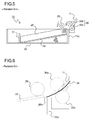
- FIG. 5 is a cross-sectional side view of a conventional sheet feeding cassette 10.
- a bundle of sheets 26 set in a cassette base 25 of the sheet feeding cassette 10 are pressed against a pickup roller 29, which is provided on an apparatus main body side, at a predetermined pressure, owing to the elevation of a sheet stacking plate 28 which is vertically raised and lowered by a lifting mechanism (not shown).
- the pickup roller 29 and a feeding roller 30a of a feeding roller pair 30 are driven and rotated in directions indicated by the arrows of FIG. 5 .
- the feeding roller pair 30 includes the feeding roller 30a and a separation roller 30b which is provided in press-contact to or apart from the feeding roller 30a.
- the separation roller 30b has a torque limiter built therein, and is rotated with the feeding roller 30a in accordance with the rotation thereof only when the rotational load exceeds the predetermined torque.
- the separation roller 30b separates only the uppermost sheet of the several sheets fed to the feeding roller pair 30, to thereby convey the sheet toward a sheet conveyance path 11.
- the cassette base 25 is provided with a trailing end cursor 31 for aligning the trailing ends of the sheets 26, the trailing end cursor 31 being movable in a sheet conveyance direction (lateral direction in FIG. 5 ).
- This flapping noise is a so-called impulse response, which corresponds to a momentarily generated high-pitched sound, and hence is extremely annoying for a user.
- noise-reduction there has been an increasing demand for noise-reduction, and therefore a measure against the flapping noise of the sheet trailing end, which is one of the factors of noise, has become important.
- the above-mentioned method of providing the notch portion in the side surface of the sheet feeding cassette or a part of the trailing end cursor it has been incapable of reducing the flapping noise of the sheet trailing end.
- a member having cushioning properties such as an elastic body is fixed to a place to which the sheet trailing end is hit, to thereby reduce the flapping noise.
- this method causes increase in material cost and manufacturing cost, and further, there is a fear that the fixed member causes harmful effects such as a jam of the sheet.
- a sheet feeding apparatus in which a plurality of ribs are formed on a guide surface of a turn guide which reverses the sheet fed from the sheet cassette and guides the reversed sheet to an image transfer portion, and a projected portion of the rib, which is projected toward the leading end of the sheet cassette, is shaped so as to become lower toward both ends from a center of the turn guide.
- the above-mentioned technology is a technology for preventing generation of the flapping noise caused by the collision of the turn guide and the trailing end of the sheet fed from the sheet cassette, and is not a technology for preventing the flapping noise caused by the collision of the sheet trailing end and the wall portion of the sheet cassette.
- the sheet is conveyed in the sheet feeding direction while the center portion in the width direction thereof, which is nipped between the feeding roller pair, bends downwardly, in the above-mentioned sheet feeding apparatus, the rib at the center of the turn guide has the largest height.
- the present invention has been made in view of the above-mentioned problems, and it is an object of the present invention to provide a recording medium storage cassette, which is capable of effectively reducing a flapping noise of a recording medium trailing end when the recording medium is fed and in which a recording medium setting property is improved, with a simple configuration and at low cost.
- a recording medium storage cassette including: a housing, which is constituted by a cassette base and a plurality of wall portions provided upright at peripheral end portions of the cassette base, for storing a recording medium of a sheet form; and a recording medium stacking plate, which is pivotably provided to the housing and has one end raised and lowered in accordance with a stacking amount of the recording medium, the recording medium storage cassette being detachably mountable to an image forming apparatus main body, in which, among the plurality of wall portions, a wall portion provided upright in a feeding direction of the recording medium includes a first notch portion formed therein, the first notch portion being opened toward an upper end of the wall portion and formed at a position facing a feeding roller, which is provided on the image forming apparatus main body side, for feeding the recording medium inside the housing.
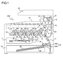
- FIG. 1 is a schematic view illustrating an inner configuration of an image forming apparatus 100 to which a sheet feeding cassette 10 according to the present invention is mounted.
- the image forming apparatus 100 is a tandem-type color copying machine, and includes four image forming portions Pa, Pb, Pc, and Pd inside an image forming apparatus 100 main body, which are arranged in the stated order from the left side in FIG. 1 .
- the image forming portions Pa to Pd are provided correspondingly to images of four different colors (yellow, magenta, cyan, and black), respectively, and the respective yellow, magenta, cyan, and black images are sequentially formed by respective steps of charging, exposure, development, and transfer.
- Those image forming portions Pa to Pd are respectively provided with photosensitive drums 1a, 1b, 1c, and 1d for bearing visible images (toner images) of the respective colors.
- an intermediate transfer belt 8 which rotates in a counterclockwise direction in FIG. 1 , is provided so as to be adjacent to the respective image forming portions Pa to Pd.
- the toner images formed on the photosensitive drums 1a to 1d, respectively, are sequentially transferred and superimposed on the intermediate transfer belt 8 which moves while being held in abutment with the respective photosensitive drums 1a to 1d.
- the toner images are transferred onto a sheet 26 as an example of a recording medium by the action of a secondary transfer roller 9, and further, fixed on the sheet 26 in a fixing device 7.
- the sheet 26 is delivered from the apparatus main body.
- the image forming process with respect to the respective photosensitive drums 1a to 1d is executed while rotating the photosensitive drums 1a to 1d in a clockwise direction in FIG. 1 .
- the sheets 26 onto which the toner image is to be transferred are stored in the sheet feeding cassette 10 provided on the lower side of the apparatus.
- the sheets 26 are stacked on a sheet stacking plate 28 of the sheet feeding cassette 10, and feeding of the sheets 26 is started by rotating a pickup roller 29 under a state in which the upper surface of the sheet 26 is held in press-contact with the pickup roller 29 at a predetermined pressure.
- a feeding roller pair 30 separates only the uppermost sheet of the several sheets 26, to thereby convey the sheet toward a sheet conveyance path 11.
- the sheet 26 passes through the sheet conveyance path 11, and then reaches to a registration roller pair 14.
- the sheet 26 is conveyed to a nip between the secondary transfer roller 9 and a drive roller 13 for the intermediate transfer belt 8 described later.
- a dielectric resin sheet is used for the intermediate transfer belt 8, and both end portions of the dielectric resin sheet are overlapped and bonded to each other to form an endless belt, or a seamless belt is used. Further, on a downstream side in a moving direction of the intermediate transfer belt 8 when viewed from the secondary transfer roller 9, a cleaning blade 17 for removing toner remaining on the surface of the intermediate transfer belt 8 is arranged.
- An image reading portion 20 includes a scanning optical system in which a scanner lamp for illuminating an original at the time of copying and a mirror for changing an optical path of light reflected from the original are mounted, a condensing lens for condensing the light reflected from the original to form an image, and a CCD sensor for converting the formed image light into an electrical signal (all members are not shown).
- the image reading portion 20 reads the image on the original and converts the read image into image data.
- charging devices 2a, 2b, 2c, and 2d for charging the photosensitive drums 1a to 1d, respectively, an exposure device 4 for performing exposure of image information onto the respective photosensitive drums 1a to 1d, development devices 3a, 3b, 3c, and 3d for forming toner images onto the photosensitive drums 1a to 1d, respectively, and cleaning devices 5a, 5b, 5c, and 5d for removing a developer (toner) remaining on the photosensitive drums 1a to 1d, respectively.
- the development devices 3a to 3d include development rollers (developer carrying members) arranged so as to be opposed to the photosensitive drums 1a to 1d, respectively, and are respectively loaded with predetermined amounts of two-component developers containing toners of the respective colors of yellow, magenta, cyan, and black.
- toners are supplied and electrostatically adhered onto the photosensitive drums 1a to 1d by the development rollers of the development devices 3a to 3d, to thereby form toner images corresponding to the electrostatic latent images formed by the exposure from the exposure device 4.
- the intermediate transfer belt 8 is looped around a driven roller 12 and the drive roller 13.
- the intermediate transfer belt 8 starts to rotate in the counterclockwise direction along with the rotation of the drive roller 13 by a belt drive motor (not shown)
- the sheet 26 is conveyed from the registration roller pair 14 to a nip portion (secondary transfer nip portion) between the secondary transfer roller 9, which is provided close to the intermediate transfer belt 8, and the intermediate transfer belt 8 at a predetermined timing.
- a full-color image is secondarily transferred onto the sheet 26.
- the sheet 26 onto which the toner image has been transferred is conveyed to the fixing device 7.
- the sheet 26 conveyed to the fixing device 7 is heated and pressurized when the sheet 26 passes through a nip portion (fixing nip portion) between a fixing roller pair 15, and thus the toner image thereon is fixed onto the surface of the sheet 26. In this manner, a predetermined full-color image is formed.
- the sheet 26 onto which the full-color image has been formed passes through a conveyance roller pair 16, and then the conveyance direction of the sheet 26 is sorted by a conveyance guide member 21 arranged at a branch portion of a sheet conveyance path 19.
- the sheet 26 is directly delivered to a delivery tray 18 via a delivery roller pair 24, or the sheet 26 is conveyed to a reverse conveyance path 23 so as to be subjected to double-sided copying, and then delivered to the delivery tray 18 via the delivery roller pair 24.
- the sheet conveyance path 19 branches into two paths of right and left on the downstream side of the conveyance roller pair 16, and one of the two paths (path branched in the left direction of FIG. 1 ) is communicated with the delivery tray 18. Further, the other of the two paths (path branched in the right direction of FIG. 1 ) is communicated with the reverse conveyance path 23.
- FIG. 2 is a perspective view illustrating a state in which the sheet feeding cassette 10 is pulled out from the image forming apparatus 100 main body.
- the arrow A and the arrow A' indicate an inserting direction and a pulling-out direction, respectively, of the sheet feeding cassette 10 with respect to the image forming apparatus 100 main body
- the arrow B indicates a sheet feeding direction of the sheet feeding cassette 10.
- Wall portions 25a to 25d are provided upright at four peripheral end portions of a cassette base 25.
- the cassette base 25 and the wall portions 25a to 25d form a housing (casing) of the sheet feeding cassette 10.
- a cassette cover 33 is mounted onto the wall portion 25c on the upstream side with respect to the inserting direction of the sheet feeding cassette 10.
- the front surface side (left side in FIG. 2 ) of the cassette cover 33 is exposed to the outside, and this part forms a part of an exterior surface of the image forming apparatus 100 main body (see FIG. 1 ).
- a gripper portion 35 is provided at a center portion of the cassette cover 33 to be used when the sheet feeding cassette 10 is detached and mounted.
- the sheet stacking plate 28 onto which the sheets 26 (see FIG. 1 ) are to be stacked is provided so that an end portion on the downstream side in the sheet feeding direction (direction of the arrow B in FIG. 2 ) is vertically liftable with respect to the cassette base 25 with pivot shafts 28a provided on the right and left sides being a fulcrum. Further, on both sides in a width direction of the sheet stacking plate 28, a pair of width adjusting cursors 37a and 37b for performing positioning in the width direction of the sheets 26 to be stacked on the sheet stacking plate 28 are provided so as to be reciprocable in the sheet width direction (directions of the arrows A and A' in FIG. 2 ) along a guide groove formed in the cassette base 25.
- a trailing end cursor 31 for aligning the trailing ends of the sheets is provided so as to be reciprocable in a direction parallel to the sheet conveyance direction (direction of the arrow B in FIG. 2 ) along a guide groove formed in the cassette base 25.
- the width adjusting cursors 37a and 37b and the trailing end cursor 31 are moved in conformity to the size of the stacked sheets, and thus, the sheets 26 are stored at a predetermined position inside the sheet feeding cassette 10.
- guide rails 40a and 40b are arranged adjacent to the wall portions 25a and 25d, respectively.
- a rail support portion (not shown) for slidably supporting the guide rails 40a and 40b is provided.
- the guide rails 40a and 40b are allowed to slide along the rail support portion, and thus the sheet feeding cassette 10 can be inserted into or pulled out from the image forming apparatus 100 main body.
- FIG. 3 is a partial side view of the sheet feeding cassette 10 viewed from the downstream side in the sheet feeding direction.
- the first notch portion 41 which is formed at a substantially center portion in a longitudinal direction of the wall portion 25a, faces the feeding roller 30a (see FIG. 1 ) on the image forming apparatus 100 main body side, and includes a tapered portion 41a which widens upwardly and a rectangular extended portion 41b provided continuously below the tapered portion 41a.
- the extended portion 41b is extended down to the vicinity of a lower end of the wall portion 25a, and the extended portion 41b is designed to have a width w1 slightly larger than the width of the feeding roller 30a.
- the two second notch portions 43 which are formed at both end portions in the longitudinal direction of the wall portion 25a, each include an inclined surface 43a which gently rises toward the first notch portion 41, and there are formed mountain-shaped sheet regulating portions 45 each having a peak 45a at a portion at which the inclined surface 43a and the tapered portion 41a of the first notch portion 41 intersect with each other.
- the sheet regulating portion 45 is a member for regulating movement in the sheet feeding direction of the sheet inside the sheet feeding cassette 10.
- the peak 45a of the sheet regulating portion 45 is formed on an inner side of a width w2 of a minimum-size sheet storable inside the sheet feeding cassette 10.
- each of the sheet regulating portions 45 is designed to have a height h which is equal to or larger than the maximum height of the sheets when the maximum amount of sheets storable inside the sheet feeding cassette 10 are stored.
- the lifting mechanism (not shown) raises the sheet stacking plate 28 so that the upper surface of the sheet bundle set on the sheet stacking plate 28 is pressed by the pickup roller 29 at a predetermined pressure.
- the pickup roller 29 and a feeding roller 30a of the feeding roller pair 30 start to rotate.
- the pickup roller 29 and the feeding roller pair 30 separate only the uppermost sheet of the sheet bundle, and the separated sheet is conveyed to the sheet conveyance path 11 (see FIG. 1 ).
- FIG. 4 is a partial side view illustrating a state in which the sheet is fed from the sheet feeding cassette 10, when viewed from the downstream side in the sheet feeding direction.
- the wall portion 25a positioned in the sheet feeding direction has the first notch portion 41 and the second notch portions 43 formed therein, and hence when the trailing end of the sheet 26 passes above the upper end of the wall portion 25a, the trailing end of the sheet 26 collides only with the peaks 45a of the sheet regulating portions 45. With this, the contact area between the trailing end of the sheet 26 and the wall portion 25a is reduced, which makes it possible to reduce the sheet flapping noise.
- the sheet 26 is conveyed in the sheet feeding direction while the center portion in the width direction thereof, which is nipped between the feeding roller pair 30, bends downwardly.
- the first notch portion 41 is formed at a portion of the wall portion 25a facing the feeding roller 30a, and the first notch portion 41 includes the tapered portion 41a which widens upwardly, it is possible to effectively avoid collision of the bending portion of the sheet 26 and the wall portion 25a.
- the peaks 45a of the sheet regulating portions 45 are arranged at positions as far from the first notch portion 41 as possible, that is, at positions on the inner side nearby the end portions in the width direction of the minimum-size sheet width w2 (see FIG. 3 ). With this, it is possible to minimize the contact between the bending portion of the sheet 26 and the sheet regulating portions 45 while maintaining the function of regulating the movement of the minimum-width sheet 26.
- the interval between the peaks 45a of the sheet regulating portions 45 is set larger than the width of the feeding roller 30a, and hence it is possible to suppress the collision of the bending portion of the sheet 26, which is formed by being nipped between the feeding roller pair 30, and the peaks 45a of the sheet regulating portions 45 more effectively.
- the bending amount of the sheet 26 differs depending on the size or the paper thickness of the sheet 26.
- the bending of the sheet 26 is small, and hence both the end portions in the width direction of the sheet 26 are easily brought into contact with the upper end of the wall portion 25a.
- both the end portions in the width direction of the sheet 26 do not collide against the wall portion 25a at once, and the sheet is fed while both the end portions are sequentially brought into contact with the upper end of the wall portion 25a along the inclined surfaces 43a. Therefore, it is possible to reduce the sheet flapping noise.
- the fingers holding the sheet bundle enter the extended portion 41b from the tapered portion 41a of the first notch portion 41, and hence it is possible to reliably set the sheet bundle down to the bottom surface of the cassette base 25.
- the sheet bundle set in the sheet feeding cassette 10 is to be replaced, by inserting the fingers into the extended portion 41b of the first notch portion 41 and holding the lowermost portion of the sheet bundle, the sheet bundle can be taken out at once.
- the wall portion 25a does not disturb the work when the sheet bundle is set or replaced, and hence the workability is improved.
- the present invention is not limited to the embodiment described above, and various modifications may be made thereto without departing from the gist of the present invention.
- the first notch portion 41 is provided at a portion of the wall portion 25a facing the feeding roller 30a
- the second notch portions 43 are provided at both the end portions in the longitudinal direction of the wall portion 25a.
- the first notch portion 41 may be provided at a portion of the wall portion 25a facing the feeding roller 30a. Also in this case, it is possible to reduce the collision with the wall portion 25a when the sheet downwardly bends by the nipping of the feeding roller pair 30. Therefore, it is possible to expect the effect of suppressing the sheet flapping noise.
- the feeding roller pair 30 is arranged at a center portion in the sheet width direction herein, and hence the first notch portion 41 is also formed at the substantially center portion in the longitudinal direction of the wall portion 25a.
- the first notch portion 41 may be also formed at other positions of the wall portion 25a in conformity to the position of the feeding roller pair 30.
- first notch portion 41 and the second notch portions 43 are not limited to those described in the embodiment above, and may be appropriately set depending on specifications of the sheet feeding cassette and the type of the sheet to be used.
- the extended portion 41b of the first notch portion 41 is not a necessary configuration, and in a case where the sheet setting property to the sheet feeding cassette 10 is not required to be considered, the extended portion 41b may be omitted.
- the present invention is applicable to a recording medium storage cassette for storing a recording medium of a sheet form.
- the wall portion provided upright in the feeding direction of the recording medium has the first notch portion formed therein, which is opened toward the upper end of the wall portion and formed at the position facing the feeding roller, which is provided on the image forming apparatus main body side.
- a recording medium storage cassette which is capable of effectively avoiding the collision of the recording medium and the wall portion provided upright in the feeding direction of the recording medium and reducing the flapping noise, with a simple configuration and at low cost.
Landscapes
- Physics & Mathematics (AREA)
- General Physics & Mathematics (AREA)
- Sheets, Magazines, And Separation Thereof (AREA)
Abstract
Description
- The present invention relates to a recording medium storage cassette for storing a recording medium of a sheet form, which is to be used in an image forming apparatus such as a digital copying machine and a laser printer, and to an image forming apparatus including the recording medium storage cassette.
- Conventionally, there has been widely used a sheet feeding cassette for storing a plurality of stacked sheets (recording media) and for conveying the sheets one by one in a separated manner to an image forming portion of an image forming apparatus main body in accordance with an image forming operation.
- A configuration of a conventional sheet feeding cassette is described.
FIG. 5 is a cross-sectional side view of a conventionalsheet feeding cassette 10. A bundle ofsheets 26 set in acassette base 25 of thesheet feeding cassette 10 are pressed against apickup roller 29, which is provided on an apparatus main body side, at a predetermined pressure, owing to the elevation of asheet stacking plate 28 which is vertically raised and lowered by a lifting mechanism (not shown). Here, when a printing operation of the image forming apparatus is started, thepickup roller 29 and afeeding roller 30a of afeeding roller pair 30 are driven and rotated in directions indicated by the arrows ofFIG. 5 . - Generally,
several sheets 26 on the upper side of the bundle set on thesheet stacking plate 28 are fed to thefeeding roller pair 30 by thepickup roller 29. Thefeeding roller pair 30 includes thefeeding roller 30a and aseparation roller 30b which is provided in press-contact to or apart from thefeeding roller 30a. Theseparation roller 30b has a torque limiter built therein, and is rotated with thefeeding roller 30a in accordance with the rotation thereof only when the rotational load exceeds the predetermined torque. Theseparation roller 30b separates only the uppermost sheet of the several sheets fed to thefeeding roller pair 30, to thereby convey the sheet toward asheet conveyance path 11. Thecassette base 25 is provided with atrailing end cursor 31 for aligning the trailing ends of thesheets 26, the trailingend cursor 31 being movable in a sheet conveyance direction (lateral direction inFIG. 5 ). - In the
sheet feeding cassette 10 described above, there has been a problem that, when the bundle of thesheets 26 are set on thesheet stacking plate 28, or when thesheets 26 once set are removed and then thesheets 26 having different size or paper quality are reset, the workability is lowered because a wall portion provided upright at a peripheral end portion of thecassette base 25 disturbs the work. - In this context, there have been proposed various sheet feeding cassettes which enable smooth supplying and removing of the sheets with respect to the sheet feeding cassette. For example, there is known a configuration in which a notch portion is provided from the side surface to the bottom surface of the sheet feeding cassette so that at least a hand is insertable. Further, there is also known a configuration in which a sheet abutment portion (trailing end cursor), which is integrally formed with a cassette plate (sheet stacking plate), is notched in part so as to provide a finger inserting portion.
- By the way, when the sheet is fed from the sheet feeding cassette as described above, there is a problem that a flapping noise of the sheet trailing end is generated. Specifically, when one
sheet 26 is conveyed toward thesheet conveyance path 11, as illustrated inFIG. 6 , after passing through a nip portion between thepickup roller 29 and thesheet stacking plate 28, atrailing end 26a of thesheet 26 being conveyed is hit to an upper end of awall portion 25a positioned in a sheet feeding direction of thecassette base 25 by the restoring force of thesheet 26. Thus, a sheet conveyance noise (flapping noise) is generated. - This flapping noise is a so-called impulse response, which corresponds to a momentarily generated high-pitched sound, and hence is extremely annoying for a user. In recent years, there has been an increasing demand for noise-reduction, and therefore a measure against the flapping noise of the sheet trailing end, which is one of the factors of noise, has become important. However, with the above-mentioned method of providing the notch portion in the side surface of the sheet feeding cassette or a part of the trailing end cursor, it has been incapable of reducing the flapping noise of the sheet trailing end.
- As a conventional measure, a member having cushioning properties such as an elastic body is fixed to a place to which the sheet trailing end is hit, to thereby reduce the flapping noise. However, because of the addition of the member, this method causes increase in material cost and manufacturing cost, and further, there is a fear that the fixed member causes harmful effects such as a jam of the sheet.
- As a method of reducing the flapping noise of the sheet trailing end, for example, there is known a sheet feeding apparatus in which a plurality of ribs are formed on a guide surface of a turn guide which reverses the sheet fed from the sheet cassette and guides the reversed sheet to an image transfer portion, and a projected portion of the rib, which is projected toward the leading end of the sheet cassette, is shaped so as to become lower toward both ends from a center of the turn guide.
- However, the above-mentioned technology is a technology for preventing generation of the flapping noise caused by the collision of the turn guide and the trailing end of the sheet fed from the sheet cassette, and is not a technology for preventing the flapping noise caused by the collision of the sheet trailing end and the wall portion of the sheet cassette. Further, although the sheet is conveyed in the sheet feeding direction while the center portion in the width direction thereof, which is nipped between the feeding roller pair, bends downwardly, in the above-mentioned sheet feeding apparatus, the rib at the center of the turn guide has the largest height. Thus, there has not been disclosed any technological idea for avoiding the collision of the sheet and the rib in consideration of the sheet bending.
- The present invention has been made in view of the above-mentioned problems, and it is an object of the present invention to provide a recording medium storage cassette, which is capable of effectively reducing a flapping noise of a recording medium trailing end when the recording medium is fed and in which a recording medium setting property is improved, with a simple configuration and at low cost.
- In order to achieve the above-mentioned object, according to one aspect of the present invention, there is provided a recording medium storage cassette, including: a housing, which is constituted by a cassette base and a plurality of wall portions provided upright at peripheral end portions of the cassette base, for storing a recording medium of a sheet form; and a recording medium stacking plate, which is pivotably provided to the housing and has one end raised and lowered in accordance with a stacking amount of the recording medium, the recording medium storage cassette being detachably mountable to an image forming apparatus main body, in which, among the plurality of wall portions, a wall portion provided upright in a feeding direction of the recording medium includes a first notch portion formed therein, the first notch portion being opened toward an upper end of the wall portion and formed at a position facing a feeding roller, which is provided on the image forming apparatus main body side, for feeding the recording medium inside the housing.
- Further features and advantages of the present invention will become apparent from the description of embodiments given below.
-
-
FIG. 1 is a schematic cross-sectional view illustrating an inner configuration of animage forming apparatus 100 to which asheet feeding cassette 10 according to the present invention is mounted. -
FIG. 2 is a perspective view of thesheet feeding cassette 10 according to an embodiment of the present invention, when viewed from a downstream side in a sheet feeding direction. -
FIG. 3 is a partial side view of thesheet feeding cassette 10 according to the embodiment of the present invention, when viewed from the downstream side in the sheet feeding direction. -
FIG. 4 is a partial side view illustrating a state in which asheet 26 is fed from thesheet feeding cassette 10 according to the embodiment of the present invention, when viewed from the downstream side in the sheet feeding direction. -
FIG. 5 is a cross-sectional side view illustrating a conventionalsheet feeding cassette 10 and a configuration around afeeding roller pair 30 provided on animage forming apparatus 100 main body side. -
FIG. 6 is a partial cross-sectional view illustrating a state in which, in the conventionalsheet feeding cassette 10, a trailing end of asheet 26 to be fed is passing above awall portion 25a of thesheet feeding cassette 10. - Hereinafter, an embodiment of the present invention is described in detail with reference to the drawings.
FIG. 1 is a schematic view illustrating an inner configuration of animage forming apparatus 100 to which asheet feeding cassette 10 according to the present invention is mounted. Theimage forming apparatus 100 is a tandem-type color copying machine, and includes four image forming portions Pa, Pb, Pc, and Pd inside animage forming apparatus 100 main body, which are arranged in the stated order from the left side inFIG. 1 . The image forming portions Pa to Pd are provided correspondingly to images of four different colors (yellow, magenta, cyan, and black), respectively, and the respective yellow, magenta, cyan, and black images are sequentially formed by respective steps of charging, exposure, development, and transfer. - Those image forming portions Pa to Pd are respectively provided with photosensitive drums 1a, 1b, 1c, and 1d for bearing visible images (toner images) of the respective colors. Further, an
intermediate transfer belt 8, which rotates in a counterclockwise direction inFIG. 1 , is provided so as to be adjacent to the respective image forming portions Pa to Pd. The toner images formed on the photosensitive drums 1a to 1d, respectively, are sequentially transferred and superimposed on theintermediate transfer belt 8 which moves while being held in abutment with the respective photosensitive drums 1a to 1d. After that, the toner images are transferred onto asheet 26 as an example of a recording medium by the action of a secondary transfer roller 9, and further, fixed on thesheet 26 in afixing device 7. Then, thesheet 26 is delivered from the apparatus main body. The image forming process with respect to the respective photosensitive drums 1a to 1d is executed while rotating the photosensitive drums 1a to 1d in a clockwise direction inFIG. 1 . - The
sheets 26 onto which the toner image is to be transferred are stored in thesheet feeding cassette 10 provided on the lower side of the apparatus. Thesheets 26 are stacked on asheet stacking plate 28 of thesheet feeding cassette 10, and feeding of thesheets 26 is started by rotating apickup roller 29 under a state in which the upper surface of thesheet 26 is held in press-contact with thepickup roller 29 at a predetermined pressure. Then, afeeding roller pair 30 separates only the uppermost sheet of theseveral sheets 26, to thereby convey the sheet toward asheet conveyance path 11. Thesheet 26 passes through thesheet conveyance path 11, and then reaches to aregistration roller pair 14. Then, at an appropriate timing for image formation, thesheet 26 is conveyed to a nip between the secondary transfer roller 9 and adrive roller 13 for theintermediate transfer belt 8 described later. - A dielectric resin sheet is used for the
intermediate transfer belt 8, and both end portions of the dielectric resin sheet are overlapped and bonded to each other to form an endless belt, or a seamless belt is used. Further, on a downstream side in a moving direction of theintermediate transfer belt 8 when viewed from the secondary transfer roller 9, acleaning blade 17 for removing toner remaining on the surface of theintermediate transfer belt 8 is arranged. - An
image reading portion 20 includes a scanning optical system in which a scanner lamp for illuminating an original at the time of copying and a mirror for changing an optical path of light reflected from the original are mounted, a condensing lens for condensing the light reflected from the original to form an image, and a CCD sensor for converting the formed image light into an electrical signal (all members are not shown). Theimage reading portion 20 reads the image on the original and converts the read image into image data. - Next, the image forming portions Pa to Pd are described. In the periphery of or below the rotatably provided photosensitive drums 1a to 1d, there are provided
charging devices development devices 3a, 3b, 3c, and 3d for forming toner images onto the photosensitive drums 1a to 1d, respectively, and cleaningdevices - When the image data is input from the
image reading portion 20, first, the surfaces of the photosensitive drums 1a to 1d are uniformly charged by thecharging devices 2a to 2d, respectively, and then, light beams are applied by the exposure device 4 correspondingly to the image data, to thereby form electrostatic latent images onto the respective photosensitive drums 1a to 1d correspondingly to the image date from theimage reading portion 20. Thedevelopment devices 3a to 3d include development rollers (developer carrying members) arranged so as to be opposed to the photosensitive drums 1a to 1d, respectively, and are respectively loaded with predetermined amounts of two-component developers containing toners of the respective colors of yellow, magenta, cyan, and black. Those toners are supplied and electrostatically adhered onto the photosensitive drums 1a to 1d by the development rollers of thedevelopment devices 3a to 3d, to thereby form toner images corresponding to the electrostatic latent images formed by the exposure from the exposure device 4. - Then, with
primary transfer rollers 6a to 6d, an electrical field is applied between theprimary transfer rollers 6a to 6d and the photosensitive drums 1a to 1d, respectively, at a predetermined transfer voltage. In this manner, the toner images of yellow, magenta, cyan, and black on the respective photosensitive drums 1a to 1d are primarily transferred onto theintermediate transfer belt 8. Those four-color images are formed with a predetermined positional relationship in order to form a predetermined full-color image. After that, for preparation of subsequent new electrostatic latent image formation, the toners remaining on the surfaces of the photosensitive drums 1a to 1d are removed by thecleaning devices 5a to 5d, respectively. - The
intermediate transfer belt 8 is looped around a drivenroller 12 and thedrive roller 13. When theintermediate transfer belt 8 starts to rotate in the counterclockwise direction along with the rotation of thedrive roller 13 by a belt drive motor (not shown), thesheet 26 is conveyed from theregistration roller pair 14 to a nip portion (secondary transfer nip portion) between the secondary transfer roller 9, which is provided close to theintermediate transfer belt 8, and theintermediate transfer belt 8 at a predetermined timing. Then, at the nip portion, a full-color image is secondarily transferred onto thesheet 26. Thesheet 26 onto which the toner image has been transferred is conveyed to thefixing device 7. - The
sheet 26 conveyed to thefixing device 7 is heated and pressurized when thesheet 26 passes through a nip portion (fixing nip portion) between a fixingroller pair 15, and thus the toner image thereon is fixed onto the surface of thesheet 26. In this manner, a predetermined full-color image is formed. Thesheet 26 onto which the full-color image has been formed passes through aconveyance roller pair 16, and then the conveyance direction of thesheet 26 is sorted by aconveyance guide member 21 arranged at a branch portion of asheet conveyance path 19. Specifically, thesheet 26 is directly delivered to adelivery tray 18 via adelivery roller pair 24, or thesheet 26 is conveyed to areverse conveyance path 23 so as to be subjected to double-sided copying, and then delivered to thedelivery tray 18 via thedelivery roller pair 24. - Specifically, the
sheet conveyance path 19 branches into two paths of right and left on the downstream side of theconveyance roller pair 16, and one of the two paths (path branched in the left direction ofFIG. 1 ) is communicated with thedelivery tray 18. Further, the other of the two paths (path branched in the right direction ofFIG. 1 ) is communicated with thereverse conveyance path 23. - Next, the configuration of the
sheet feeding cassette 10 is described.FIG. 2 is a perspective view illustrating a state in which thesheet feeding cassette 10 is pulled out from theimage forming apparatus 100 main body. InFIG. 2 , the arrow A and the arrow A' indicate an inserting direction and a pulling-out direction, respectively, of thesheet feeding cassette 10 with respect to theimage forming apparatus 100 main body, and the arrow B indicates a sheet feeding direction of thesheet feeding cassette 10.Wall portions 25a to 25d are provided upright at four peripheral end portions of acassette base 25. Thecassette base 25 and thewall portions 25a to 25d form a housing (casing) of thesheet feeding cassette 10. - A
cassette cover 33 is mounted onto thewall portion 25c on the upstream side with respect to the inserting direction of thesheet feeding cassette 10. The front surface side (left side inFIG. 2 ) of thecassette cover 33 is exposed to the outside, and this part forms a part of an exterior surface of theimage forming apparatus 100 main body (seeFIG. 1 ). Further, at a center portion of thecassette cover 33, there is provided agripper portion 35 to be used when thesheet feeding cassette 10 is detached and mounted. - The
sheet stacking plate 28 onto which the sheets 26 (seeFIG. 1 ) are to be stacked is provided so that an end portion on the downstream side in the sheet feeding direction (direction of the arrow B inFIG. 2 ) is vertically liftable with respect to thecassette base 25 withpivot shafts 28a provided on the right and left sides being a fulcrum. Further, on both sides in a width direction of thesheet stacking plate 28, a pair ofwidth adjusting cursors sheets 26 to be stacked on thesheet stacking plate 28 are provided so as to be reciprocable in the sheet width direction (directions of the arrows A and A' inFIG. 2 ) along a guide groove formed in thecassette base 25. Further, because the sheet is sent toward the sheet conveyance path 11 (seeFIG. 1 ) in the direction of the arrow B, a trailingend cursor 31 for aligning the trailing ends of the sheets is provided so as to be reciprocable in a direction parallel to the sheet conveyance direction (direction of the arrow B inFIG. 2 ) along a guide groove formed in thecassette base 25. - The
width adjusting cursors end cursor 31 are moved in conformity to the size of the stacked sheets, and thus, thesheets 26 are stored at a predetermined position inside thesheet feeding cassette 10. - On outer sides of the
wall portions sheet feeding cassette 10,guide rails wall portions image forming apparatus 100 main body side, a rail support portion (not shown) for slidably supporting theguide rails sheet feeding cassette 10 can be inserted into or pulled out from theimage forming apparatus 100 main body. -
FIG. 3 is a partial side view of thesheet feeding cassette 10 viewed from the downstream side in the sheet feeding direction. In thewall portion 25a positioned on the downstream side in the sheet feeding direction, three notch portions in total, that is, afirst notch portion 41 andsecond notch portions first notch portion 41, which is formed at a substantially center portion in a longitudinal direction of thewall portion 25a, faces the feedingroller 30a (seeFIG. 1 ) on theimage forming apparatus 100 main body side, and includes a taperedportion 41a which widens upwardly and a rectangularextended portion 41b provided continuously below the taperedportion 41a. Theextended portion 41b is extended down to the vicinity of a lower end of thewall portion 25a, and theextended portion 41b is designed to have a width w1 slightly larger than the width of the feedingroller 30a. - The two
second notch portions 43, which are formed at both end portions in the longitudinal direction of thewall portion 25a, each include aninclined surface 43a which gently rises toward thefirst notch portion 41, and there are formed mountain-shapedsheet regulating portions 45 each having apeak 45a at a portion at which theinclined surface 43a and the taperedportion 41a of thefirst notch portion 41 intersect with each other. Thesheet regulating portion 45 is a member for regulating movement in the sheet feeding direction of the sheet inside thesheet feeding cassette 10. Thepeak 45a of thesheet regulating portion 45 is formed on an inner side of a width w2 of a minimum-size sheet storable inside thesheet feeding cassette 10. Further, each of thesheet regulating portions 45 is designed to have a height h which is equal to or larger than the maximum height of the sheets when the maximum amount of sheets storable inside thesheet feeding cassette 10 are stored. - Next, a sheet feeding operation utilizing the
sheet feeding cassette 10 of the present invention is described. When a copying start button of theimage forming apparatus 100 is turned ON, the lifting mechanism (not shown) raises thesheet stacking plate 28 so that the upper surface of the sheet bundle set on thesheet stacking plate 28 is pressed by thepickup roller 29 at a predetermined pressure. At the same time, thepickup roller 29 and afeeding roller 30a of the feeding roller pair 30 (seeFIG. 1 ) start to rotate. Then, thepickup roller 29 and the feedingroller pair 30 separate only the uppermost sheet of the sheet bundle, and the separated sheet is conveyed to the sheet conveyance path 11 (seeFIG. 1 ). -
FIG. 4 is a partial side view illustrating a state in which the sheet is fed from thesheet feeding cassette 10, when viewed from the downstream side in the sheet feeding direction. Thewall portion 25a positioned in the sheet feeding direction has thefirst notch portion 41 and thesecond notch portions 43 formed therein, and hence when the trailing end of thesheet 26 passes above the upper end of thewall portion 25a, the trailing end of thesheet 26 collides only with thepeaks 45a of thesheet regulating portions 45. With this, the contact area between the trailing end of thesheet 26 and thewall portion 25a is reduced, which makes it possible to reduce the sheet flapping noise. - Further, as illustrated by a solid line in
FIG. 4 , thesheet 26 is conveyed in the sheet feeding direction while the center portion in the width direction thereof, which is nipped between the feedingroller pair 30, bends downwardly. Here, because thefirst notch portion 41 is formed at a portion of thewall portion 25a facing the feedingroller 30a, and thefirst notch portion 41 includes the taperedportion 41a which widens upwardly, it is possible to effectively avoid collision of the bending portion of thesheet 26 and thewall portion 25a. - Therefore, in order to reduce the contact between the bending portion of the
sheet 26 and thesheet regulating portions 45 as much as possible, it is desired to widen the interval between thepeaks 45a of thesheet regulating portions 45 as much as possible. In this context, it is preferred to arrange thepeaks 45a of thesheet regulating portions 45 at positions as far from thefirst notch portion 41 as possible, that is, at positions on the inner side nearby the end portions in the width direction of the minimum-size sheet width w2 (seeFIG. 3 ). With this, it is possible to minimize the contact between the bending portion of thesheet 26 and thesheet regulating portions 45 while maintaining the function of regulating the movement of the minimum-width sheet 26. - Further, the interval between the
peaks 45a of thesheet regulating portions 45 is set larger than the width of the feedingroller 30a, and hence it is possible to suppress the collision of the bending portion of thesheet 26, which is formed by being nipped between the feedingroller pair 30, and thepeaks 45a of thesheet regulating portions 45 more effectively. - Note that, the bending amount of the
sheet 26 differs depending on the size or the paper thickness of thesheet 26. However, when thesheet 26 has a high stiffness, as illustrated by a broken line inFIG. 4 , the bending of thesheet 26 is small, and hence both the end portions in the width direction of thesheet 26 are easily brought into contact with the upper end of thewall portion 25a. However, even in this case, both the end portions in the width direction of thesheet 26 do not collide against thewall portion 25a at once, and the sheet is fed while both the end portions are sequentially brought into contact with the upper end of thewall portion 25a along theinclined surfaces 43a. Therefore, it is possible to reduce the sheet flapping noise. - Further, when the sheet bundle is to be set on the
sheet stacking plate 28 of thesheet feeding cassette 10, by holding a portion of the sheet bundle near the center in the width direction, and by placing the leading end of the sheet bundle on thesheet stacking plate 28 from thewall portion 25d side (trailingend cursor 31 side) and then on thewall portion 25a side, the fingers holding the sheet bundle enter theextended portion 41b from the taperedportion 41a of thefirst notch portion 41, and hence it is possible to reliably set the sheet bundle down to the bottom surface of thecassette base 25. Meanwhile, in a case where the sheet bundle set in thesheet feeding cassette 10 is to be replaced, by inserting the fingers into theextended portion 41b of thefirst notch portion 41 and holding the lowermost portion of the sheet bundle, the sheet bundle can be taken out at once. With this, thewall portion 25a does not disturb the work when the sheet bundle is set or replaced, and hence the workability is improved. - Besides, the present invention is not limited to the embodiment described above, and various modifications may be made thereto without departing from the gist of the present invention. For example, in the embodiment described above, the
first notch portion 41 is provided at a portion of thewall portion 25a facing the feedingroller 30a, and thesecond notch portions 43 are provided at both the end portions in the longitudinal direction of thewall portion 25a. However, without providing thesecond notch portions 43, only thefirst notch portion 41 may be provided at a portion of thewall portion 25a facing the feedingroller 30a. Also in this case, it is possible to reduce the collision with thewall portion 25a when the sheet downwardly bends by the nipping of the feedingroller pair 30. Therefore, it is possible to expect the effect of suppressing the sheet flapping noise. - Further, the feeding
roller pair 30 is arranged at a center portion in the sheet width direction herein, and hence thefirst notch portion 41 is also formed at the substantially center portion in the longitudinal direction of thewall portion 25a. However, in a case where the feedingroller pair 30 is arranged at other positions, thefirst notch portion 41 may be also formed at other positions of thewall portion 25a in conformity to the position of the feedingroller pair 30. - Still further, the shapes and the sizes of the
first notch portion 41 and thesecond notch portions 43 are not limited to those described in the embodiment above, and may be appropriately set depending on specifications of the sheet feeding cassette and the type of the sheet to be used. For example, theextended portion 41b of thefirst notch portion 41 is not a necessary configuration, and in a case where the sheet setting property to thesheet feeding cassette 10 is not required to be considered, theextended portion 41b may be omitted. - The present invention is applicable to a recording medium storage cassette for storing a recording medium of a sheet form. In the present invention, of the plurality of wall portions provided upright at peripheral end portions of the cassette base, the wall portion provided upright in the feeding direction of the recording medium has the first notch portion formed therein, which is opened toward the upper end of the wall portion and formed at the position facing the feeding roller, which is provided on the image forming apparatus main body side.
- By utilizing the present invention, it is possible to provide a recording medium storage cassette, which is capable of effectively avoiding the collision of the recording medium and the wall portion provided upright in the feeding direction of the recording medium and reducing the flapping noise, with a simple configuration and at low cost.
- The above embodiments of the invention as well as the appended claims and figures show multiple characterizing features of the invention in specific combinations. The skilled person will easily be able to consider further combinations or sub-combinations of these features in order to adapt the invention as defined in the claims to his specific needs.
Claims (7)
- A recording medium storage cassette (10), comprising:a housing, which is constituted by a cassette base (25) and a plurality of wall portions (25a to 25d) provided upright at peripheral end portions of the cassette base (25), for storing a recording medium of a sheet form; anda recording medium stacking plate (28), which is pivotably provided to the housing and has one end raised and lowered in accordance with a stacking amount of the recording medium,the recording medium storage cassette (10) being detachably mountable to an image forming apparatus (100) main body,the recording medium storage cassette (10) being characterized in that, among the plurality of wall portions (25a to 25d), a wall portion (25a) provided upright in a feeding direction of the recording medium comprises a first notch portion (41) formed therein, the first notch portion (41) being opened toward an upper end of the wall portion (25a) and formed at a position facing a feeding roller (30a), which is provided on the image forming apparatus (100) main body side, for feeding the recording medium inside the housing.
- A recording medium storage cassette according to claim 1, characterized in that the wall portion (25a) comprises:second notch portions (43) formed at both end portions in a longitudinal direction of an upper end portion of the wall portion (25a); andrecording medium regulating portions (45) formed between the first notch portion (41) and the respective second notch portions (43), the recording medium regulating portions (45) regulating movement in the feeding direction of the recording medium inside the housing.
- A recording medium storage cassette according to claim 2, characterized in that the recording medium regulating portions (45) each have a mountain shape with a peak (45a), when viewed from the feeding direction of the recording medium.
- A recording medium storage cassette according to claim 3, characterized in that an interval between the peaks (45a) of the recording medium regulating portions (45) is larger than a width of the feeding roller (30a).
- A recording medium storage cassette according to claim 4, characterized in that the peak (45a) of each of the recording medium regulating portions (45) is arranged at a position on an inner side nearby an end portion in a width direction of a minimum-width recording medium which is storable inside the housing, when viewed from the feeding direction of the recording medium.
- A recording medium storage cassette according to any one of claims 1 to 5, characterized in that:the first notch portion (41) comprises:a tapered portion (41a), which widens toward the upper end of the wall portion (25a); andan extended portion (41b) provided continuously below the tapered portion (41a); andthe extended portion (41b) is extended down to a vicinity of a lower end of the wall portion (25a).
- An image forming apparatus, comprising the recording medium storage cassette according to any one of claims 1 to 6.
Applications Claiming Priority (1)
| Application Number | Priority Date | Filing Date | Title |
|---|---|---|---|
| JP2010245808A JP5325868B2 (en) | 2010-11-02 | 2010-11-02 | Recording medium storage cassette and image forming apparatus having the same |
Publications (3)
| Publication Number | Publication Date |
|---|---|
| EP2447782A2 true EP2447782A2 (en) | 2012-05-02 |
| EP2447782A3 EP2447782A3 (en) | 2017-03-15 |
| EP2447782B1 EP2447782B1 (en) | 2019-03-13 |
Family
ID=44763914
Family Applications (1)
| Application Number | Title | Priority Date | Filing Date |
|---|---|---|---|
| EP11182881.0A Active EP2447782B1 (en) | 2010-11-02 | 2011-09-27 | Recording medium storage cassette and image forming apparatus including the same |
Country Status (5)
| Country | Link |
|---|---|
| US (1) | US8777213B2 (en) |
| EP (1) | EP2447782B1 (en) |
| JP (1) | JP5325868B2 (en) |
| KR (1) | KR101286885B1 (en) |
| CN (1) | CN102530591B (en) |
Families Citing this family (4)
| Publication number | Priority date | Publication date | Assignee | Title |
|---|---|---|---|---|
| JP5574100B2 (en) * | 2010-05-28 | 2014-08-20 | セイコーエプソン株式会社 | Medium storage cassette and recording device |
| JP6459048B2 (en) * | 2015-01-30 | 2019-01-30 | 株式会社リコー | Sheet material container, sheet feeding device, and image forming apparatus |
| CN108806063B (en) * | 2018-04-26 | 2020-08-18 | 深圳怡化电脑股份有限公司 | Banknote sorting mechanism, depositing and withdrawing equipment, and method and device for separating overlapped banknotes |
| JP2024029731A (en) * | 2022-08-22 | 2024-03-06 | セイコーエプソン株式会社 | Media supply system, recording system |
Family Cites Families (17)
| Publication number | Priority date | Publication date | Assignee | Title |
|---|---|---|---|---|
| JPH0356338A (en) * | 1989-07-26 | 1991-03-11 | Mita Ind Co Ltd | Overlapped feeding preventing structure |
| JPH0388630A (en) | 1989-08-31 | 1991-04-15 | Canon Inc | Sheet feeding cassette |
| JPH04209137A (en) | 1990-11-30 | 1992-07-30 | Mita Ind Co Ltd | Sheet feed cassette |
| JPH0628515A (en) | 1992-12-15 | 1994-02-04 | Casio Comput Co Ltd | Color code identification method |
| JPH0683645U (en) * | 1993-05-14 | 1994-11-29 | ブラザー工業株式会社 | Paper feeding device in printing device |
| JP4209137B2 (en) | 2001-06-08 | 2009-01-14 | 株式会社クラレ | Process for producing benzothiophenes |
| KR100423465B1 (en) * | 2002-04-11 | 2004-03-18 | 삼성전자주식회사 | apparatus for guiding a printing paper in an office machine |
| US6840511B1 (en) * | 2003-07-07 | 2005-01-11 | Lite-On Technology Corporation | Indication structure for paper reserves adapted for auto document feed apparatus |
| JP4636266B2 (en) * | 2005-01-31 | 2011-02-23 | セイコーエプソン株式会社 | Feeding cassette, recording apparatus, and liquid ejecting apparatus |
| JP4393396B2 (en) * | 2005-02-09 | 2010-01-06 | 京セラミタ株式会社 | Paper storage device |
| JP2006219243A (en) * | 2005-02-09 | 2006-08-24 | Canon Inc | Paper cassette |
| JP2008169000A (en) * | 2007-01-12 | 2008-07-24 | Funai Electric Co Ltd | Paper feeding cartridge |
| JP4987536B2 (en) * | 2007-03-28 | 2012-07-25 | 京セラドキュメントソリューションズ株式会社 | Paper cassette and image forming apparatus |
| JP4420071B2 (en) * | 2007-06-28 | 2010-02-24 | ブラザー工業株式会社 | Image forming apparatus |
| JP2009120340A (en) * | 2007-11-15 | 2009-06-04 | Canon Inc | Sheet feeding apparatus and image forming apparatus |
| JP2010013209A (en) * | 2008-07-01 | 2010-01-21 | Kyocera Mita Corp | Paper feeding device and image forming device equipped with the same |
| JP2013043737A (en) * | 2011-08-23 | 2013-03-04 | Oki Data Corp | Medium loading device and image forming apparatus |
-
2010
- 2010-11-02 JP JP2010245808A patent/JP5325868B2/en active Active
-
2011
- 2011-09-15 US US13/233,511 patent/US8777213B2/en active Active
- 2011-09-27 EP EP11182881.0A patent/EP2447782B1/en active Active
- 2011-10-19 CN CN201110318301.5A patent/CN102530591B/en active Active
- 2011-10-20 KR KR1020110107478A patent/KR101286885B1/en active Active
Non-Patent Citations (1)
| Title |
|---|
| None |
Also Published As
| Publication number | Publication date |
|---|---|
| EP2447782A3 (en) | 2017-03-15 |
| EP2447782B1 (en) | 2019-03-13 |
| CN102530591B (en) | 2015-03-11 |
| CN102530591A (en) | 2012-07-04 |
| KR101286885B1 (en) | 2013-07-16 |
| US20120104687A1 (en) | 2012-05-03 |
| JP5325868B2 (en) | 2013-10-23 |
| US8777213B2 (en) | 2014-07-15 |
| JP2012096889A (en) | 2012-05-24 |
| KR20120046682A (en) | 2012-05-10 |
Similar Documents
| Publication | Publication Date | Title |
|---|---|---|
| US8579282B2 (en) | Image forming apparatus | |
| KR101512357B1 (en) | Sheet transport apparatus, image reading apparatus including the same and image forming apparatus | |
| EP2447782B1 (en) | Recording medium storage cassette and image forming apparatus including the same | |
| US9079727B2 (en) | Sheet feeding device and image forming apparatus | |
| US20240300757A1 (en) | Sheet feeding device and image forming apparatus incorporating the same | |
| JP5771590B2 (en) | Paper feeding device, and image reading device and image forming apparatus provided with the same | |
| JP2014133629A (en) | Sheet transfer device, image reader including the same, and image formation device including the same | |
| JP6338014B2 (en) | Image forming apparatus | |
| JP6428674B2 (en) | Sheet conveying apparatus and image forming apparatus having the same | |
| JP5597570B2 (en) | Paper feeding device and image forming apparatus using the same | |
| JP7537122B2 (en) | SHEET DISCHARGE DEVICE, DOCUMENT CONVEYING DEVICE, AND IMAGE FORMING APPARATUS EQUIPPED WITH SAME | |
| JP2003118865A (en) | Sheet material feeding device and image processing device | |
| JP2001121783A (en) | Sheet ejection device | |
| JP4982872B2 (en) | Image forming apparatus | |
| JP5779574B2 (en) | Recording medium storage cassette and image forming apparatus having the same | |
| JP7625963B2 (en) | SHEET DISCHARGE DEVICE, DOCUMENT CONVEYING DEVICE, AND IMAGE FORMING APPARATUS EQUIPPED WITH SAME | |
| JP6529249B2 (en) | Sheet conveying apparatus and image forming apparatus | |
| WO2015072246A1 (en) | Sheet feeder, and image forming device provided therewith | |
| JP2019089610A (en) | Sheet discharge apparatus and image reading apparatus | |
| JP2025068322A (en) | Paper feeding device, pressing unit, image reading device, and image forming device | |
| JP6500850B2 (en) | Sheet stacking tray, sheet post-processing apparatus provided with the same, and image forming apparatus | |
| JP6685679B2 (en) | Sheet feeding apparatus and image forming apparatus | |
| JP2015164879A (en) | Paper feeder, image reader including the same, and image formation apparatus | |
| JP2016166065A (en) | Sheet conveyance device and image formation apparatus having the same | |
| JP4518404B2 (en) | Automatic document feeder and image forming apparatus |
Legal Events
| Date | Code | Title | Description |
|---|---|---|---|
| PUAI | Public reference made under article 153(3) epc to a published international application that has entered the european phase |
Free format text: ORIGINAL CODE: 0009012 |
|
| AK | Designated contracting states |
Kind code of ref document: A2 Designated state(s): AL AT BE BG CH CY CZ DE DK EE ES FI FR GB GR HR HU IE IS IT LI LT LU LV MC MK MT NL NO PL PT RO RS SE SI SK SM TR |
|
| AX | Request for extension of the european patent |
Extension state: BA ME |
|
| RAP1 | Party data changed (applicant data changed or rights of an application transferred) |
Owner name: KYOCERA DOCUMENT SOLUTIONS INC. |
|
| PUAL | Search report despatched |
Free format text: ORIGINAL CODE: 0009013 |
|
| AK | Designated contracting states |
Kind code of ref document: A3 Designated state(s): AL AT BE BG CH CY CZ DE DK EE ES FI FR GB GR HR HU IE IS IT LI LT LU LV MC MK MT NL NO PL PT RO RS SE SI SK SM TR |
|
| AX | Request for extension of the european patent |
Extension state: BA ME |
|
| RIC1 | Information provided on ipc code assigned before grant |
Ipc: G03G 15/00 20060101AFI20170209BHEP |
|
| STAA | Information on the status of an ep patent application or granted ep patent |
Free format text: STATUS: REQUEST FOR EXAMINATION WAS MADE |
|
| 17P | Request for examination filed |
Effective date: 20170717 |
|
| RBV | Designated contracting states (corrected) |
Designated state(s): AL AT BE BG CH CY CZ DE DK EE ES FI FR GB GR HR HU IE IS IT LI LT LU LV MC MK MT NL NO PL PT RO RS SE SI SK SM TR |
|
| STAA | Information on the status of an ep patent application or granted ep patent |
Free format text: STATUS: EXAMINATION IS IN PROGRESS |
|
| 17Q | First examination report despatched |
Effective date: 20180109 |
|
| GRAP | Despatch of communication of intention to grant a patent |
Free format text: ORIGINAL CODE: EPIDOSNIGR1 |
|
| STAA | Information on the status of an ep patent application or granted ep patent |
Free format text: STATUS: GRANT OF PATENT IS INTENDED |
|
| INTG | Intention to grant announced |
Effective date: 20180924 |
|
| GRAS | Grant fee paid |
Free format text: ORIGINAL CODE: EPIDOSNIGR3 |
|
| GRAA | (expected) grant |
Free format text: ORIGINAL CODE: 0009210 |
|
| STAA | Information on the status of an ep patent application or granted ep patent |
Free format text: STATUS: THE PATENT HAS BEEN GRANTED |
|
| AK | Designated contracting states |
Kind code of ref document: B1 Designated state(s): AL AT BE BG CH CY CZ DE DK EE ES FI FR GB GR HR HU IE IS IT LI LT LU LV MC MK MT NL NO PL PT RO RS SE SI SK SM TR |
|
| REG | Reference to a national code |
Ref country code: GB Ref legal event code: FG4D |
|
| REG | Reference to a national code |
Ref country code: CH Ref legal event code: EP Ref country code: AT Ref legal event code: REF Ref document number: 1108525 Country of ref document: AT Kind code of ref document: T Effective date: 20190315 |
|
| REG | Reference to a national code |
Ref country code: IE Ref legal event code: FG4D |
|
| REG | Reference to a national code |
Ref country code: DE Ref legal event code: R096 Ref document number: 602011057066 Country of ref document: DE |
|
| REG | Reference to a national code |
Ref country code: NL Ref legal event code: MP Effective date: 20190313 |
|
| REG | Reference to a national code |
Ref country code: LT Ref legal event code: MG4D |
|
| PG25 | Lapsed in a contracting state [announced via postgrant information from national office to epo] |
Ref country code: FI Free format text: LAPSE BECAUSE OF FAILURE TO SUBMIT A TRANSLATION OF THE DESCRIPTION OR TO PAY THE FEE WITHIN THE PRESCRIBED TIME-LIMIT Effective date: 20190313 Ref country code: LT Free format text: LAPSE BECAUSE OF FAILURE TO SUBMIT A TRANSLATION OF THE DESCRIPTION OR TO PAY THE FEE WITHIN THE PRESCRIBED TIME-LIMIT Effective date: 20190313 Ref country code: SE Free format text: LAPSE BECAUSE OF FAILURE TO SUBMIT A TRANSLATION OF THE DESCRIPTION OR TO PAY THE FEE WITHIN THE PRESCRIBED TIME-LIMIT Effective date: 20190313 Ref country code: NO Free format text: LAPSE BECAUSE OF FAILURE TO SUBMIT A TRANSLATION OF THE DESCRIPTION OR TO PAY THE FEE WITHIN THE PRESCRIBED TIME-LIMIT Effective date: 20190613 |
|
| PG25 | Lapsed in a contracting state [announced via postgrant information from national office to epo] |
Ref country code: RS Free format text: LAPSE BECAUSE OF FAILURE TO SUBMIT A TRANSLATION OF THE DESCRIPTION OR TO PAY THE FEE WITHIN THE PRESCRIBED TIME-LIMIT Effective date: 20190313 Ref country code: NL Free format text: LAPSE BECAUSE OF FAILURE TO SUBMIT A TRANSLATION OF THE DESCRIPTION OR TO PAY THE FEE WITHIN THE PRESCRIBED TIME-LIMIT Effective date: 20190313 Ref country code: LV Free format text: LAPSE BECAUSE OF FAILURE TO SUBMIT A TRANSLATION OF THE DESCRIPTION OR TO PAY THE FEE WITHIN THE PRESCRIBED TIME-LIMIT Effective date: 20190313 Ref country code: GR Free format text: LAPSE BECAUSE OF FAILURE TO SUBMIT A TRANSLATION OF THE DESCRIPTION OR TO PAY THE FEE WITHIN THE PRESCRIBED TIME-LIMIT Effective date: 20190614 Ref country code: HR Free format text: LAPSE BECAUSE OF FAILURE TO SUBMIT A TRANSLATION OF THE DESCRIPTION OR TO PAY THE FEE WITHIN THE PRESCRIBED TIME-LIMIT Effective date: 20190313 Ref country code: BG Free format text: LAPSE BECAUSE OF FAILURE TO SUBMIT A TRANSLATION OF THE DESCRIPTION OR TO PAY THE FEE WITHIN THE PRESCRIBED TIME-LIMIT Effective date: 20190613 |
|
| REG | Reference to a national code |
Ref country code: AT Ref legal event code: MK05 Ref document number: 1108525 Country of ref document: AT Kind code of ref document: T Effective date: 20190313 |
|
| PG25 | Lapsed in a contracting state [announced via postgrant information from national office to epo] |
Ref country code: EE Free format text: LAPSE BECAUSE OF FAILURE TO SUBMIT A TRANSLATION OF THE DESCRIPTION OR TO PAY THE FEE WITHIN THE PRESCRIBED TIME-LIMIT Effective date: 20190313 Ref country code: IT Free format text: LAPSE BECAUSE OF FAILURE TO SUBMIT A TRANSLATION OF THE DESCRIPTION OR TO PAY THE FEE WITHIN THE PRESCRIBED TIME-LIMIT Effective date: 20190313 Ref country code: CZ Free format text: LAPSE BECAUSE OF FAILURE TO SUBMIT A TRANSLATION OF THE DESCRIPTION OR TO PAY THE FEE WITHIN THE PRESCRIBED TIME-LIMIT Effective date: 20190313 Ref country code: RO Free format text: LAPSE BECAUSE OF FAILURE TO SUBMIT A TRANSLATION OF THE DESCRIPTION OR TO PAY THE FEE WITHIN THE PRESCRIBED TIME-LIMIT Effective date: 20190313 Ref country code: ES Free format text: LAPSE BECAUSE OF FAILURE TO SUBMIT A TRANSLATION OF THE DESCRIPTION OR TO PAY THE FEE WITHIN THE PRESCRIBED TIME-LIMIT Effective date: 20190313 Ref country code: SK Free format text: LAPSE BECAUSE OF FAILURE TO SUBMIT A TRANSLATION OF THE DESCRIPTION OR TO PAY THE FEE WITHIN THE PRESCRIBED TIME-LIMIT Effective date: 20190313 Ref country code: PT Free format text: LAPSE BECAUSE OF FAILURE TO SUBMIT A TRANSLATION OF THE DESCRIPTION OR TO PAY THE FEE WITHIN THE PRESCRIBED TIME-LIMIT Effective date: 20190713 Ref country code: AL Free format text: LAPSE BECAUSE OF FAILURE TO SUBMIT A TRANSLATION OF THE DESCRIPTION OR TO PAY THE FEE WITHIN THE PRESCRIBED TIME-LIMIT Effective date: 20190313 |
|
| PG25 | Lapsed in a contracting state [announced via postgrant information from national office to epo] |
Ref country code: PL Free format text: LAPSE BECAUSE OF FAILURE TO SUBMIT A TRANSLATION OF THE DESCRIPTION OR TO PAY THE FEE WITHIN THE PRESCRIBED TIME-LIMIT Effective date: 20190313 Ref country code: SM Free format text: LAPSE BECAUSE OF FAILURE TO SUBMIT A TRANSLATION OF THE DESCRIPTION OR TO PAY THE FEE WITHIN THE PRESCRIBED TIME-LIMIT Effective date: 20190313 |
|
| REG | Reference to a national code |
Ref country code: DE Ref legal event code: R097 Ref document number: 602011057066 Country of ref document: DE |
|
| PG25 | Lapsed in a contracting state [announced via postgrant information from national office to epo] |
Ref country code: AT Free format text: LAPSE BECAUSE OF FAILURE TO SUBMIT A TRANSLATION OF THE DESCRIPTION OR TO PAY THE FEE WITHIN THE PRESCRIBED TIME-LIMIT Effective date: 20190313 Ref country code: IS Free format text: LAPSE BECAUSE OF FAILURE TO SUBMIT A TRANSLATION OF THE DESCRIPTION OR TO PAY THE FEE WITHIN THE PRESCRIBED TIME-LIMIT Effective date: 20190713 |
|
| PLBE | No opposition filed within time limit |
Free format text: ORIGINAL CODE: 0009261 |
|
| STAA | Information on the status of an ep patent application or granted ep patent |
Free format text: STATUS: NO OPPOSITION FILED WITHIN TIME LIMIT |
|
| PG25 | Lapsed in a contracting state [announced via postgrant information from national office to epo] |
Ref country code: DK Free format text: LAPSE BECAUSE OF FAILURE TO SUBMIT A TRANSLATION OF THE DESCRIPTION OR TO PAY THE FEE WITHIN THE PRESCRIBED TIME-LIMIT Effective date: 20190313 |
|
| 26N | No opposition filed |
Effective date: 20191216 |
|
| PG25 | Lapsed in a contracting state [announced via postgrant information from national office to epo] |
Ref country code: SI Free format text: LAPSE BECAUSE OF FAILURE TO SUBMIT A TRANSLATION OF THE DESCRIPTION OR TO PAY THE FEE WITHIN THE PRESCRIBED TIME-LIMIT Effective date: 20190313 |
|
| PG25 | Lapsed in a contracting state [announced via postgrant information from national office to epo] |
Ref country code: TR Free format text: LAPSE BECAUSE OF FAILURE TO SUBMIT A TRANSLATION OF THE DESCRIPTION OR TO PAY THE FEE WITHIN THE PRESCRIBED TIME-LIMIT Effective date: 20190313 |
|
| PG25 | Lapsed in a contracting state [announced via postgrant information from national office to epo] |
Ref country code: MC Free format text: LAPSE BECAUSE OF FAILURE TO SUBMIT A TRANSLATION OF THE DESCRIPTION OR TO PAY THE FEE WITHIN THE PRESCRIBED TIME-LIMIT Effective date: 20190313 |
|
| REG | Reference to a national code |
Ref country code: CH Ref legal event code: PL |
|
| PG25 | Lapsed in a contracting state [announced via postgrant information from national office to epo] |
Ref country code: LU Free format text: LAPSE BECAUSE OF NON-PAYMENT OF DUE FEES Effective date: 20190927 Ref country code: LI Free format text: LAPSE BECAUSE OF NON-PAYMENT OF DUE FEES Effective date: 20190930 Ref country code: IE Free format text: LAPSE BECAUSE OF NON-PAYMENT OF DUE FEES Effective date: 20190927 Ref country code: CH Free format text: LAPSE BECAUSE OF NON-PAYMENT OF DUE FEES Effective date: 20190930 |
|
| REG | Reference to a national code |
Ref country code: BE Ref legal event code: MM Effective date: 20190930 |
|
| PG25 | Lapsed in a contracting state [announced via postgrant information from national office to epo] |
Ref country code: BE Free format text: LAPSE BECAUSE OF NON-PAYMENT OF DUE FEES Effective date: 20190930 |
|
| PG25 | Lapsed in a contracting state [announced via postgrant information from national office to epo] |
Ref country code: CY Free format text: LAPSE BECAUSE OF FAILURE TO SUBMIT A TRANSLATION OF THE DESCRIPTION OR TO PAY THE FEE WITHIN THE PRESCRIBED TIME-LIMIT Effective date: 20190313 |
|
| PG25 | Lapsed in a contracting state [announced via postgrant information from national office to epo] |
Ref country code: HU Free format text: LAPSE BECAUSE OF FAILURE TO SUBMIT A TRANSLATION OF THE DESCRIPTION OR TO PAY THE FEE WITHIN THE PRESCRIBED TIME-LIMIT; INVALID AB INITIO Effective date: 20110927 Ref country code: MT Free format text: LAPSE BECAUSE OF FAILURE TO SUBMIT A TRANSLATION OF THE DESCRIPTION OR TO PAY THE FEE WITHIN THE PRESCRIBED TIME-LIMIT Effective date: 20190313 |
|
| PG25 | Lapsed in a contracting state [announced via postgrant information from national office to epo] |
Ref country code: MK Free format text: LAPSE BECAUSE OF FAILURE TO SUBMIT A TRANSLATION OF THE DESCRIPTION OR TO PAY THE FEE WITHIN THE PRESCRIBED TIME-LIMIT Effective date: 20190313 |
|
| P01 | Opt-out of the competence of the unified patent court (upc) registered |
Effective date: 20230420 |
|
| PGFP | Annual fee paid to national office [announced via postgrant information from national office to epo] |
Ref country code: DE Payment date: 20250820 Year of fee payment: 15 |
|
| PGFP | Annual fee paid to national office [announced via postgrant information from national office to epo] |
Ref country code: GB Payment date: 20250820 Year of fee payment: 15 |
|
| PGFP | Annual fee paid to national office [announced via postgrant information from national office to epo] |
Ref country code: FR Payment date: 20250820 Year of fee payment: 15 |