JP6529249B2 - Sheet conveying apparatus and image forming apparatus - Google Patents
Sheet conveying apparatus and image forming apparatus Download PDFInfo
- Publication number
- JP6529249B2 JP6529249B2 JP2014246302A JP2014246302A JP6529249B2 JP 6529249 B2 JP6529249 B2 JP 6529249B2 JP 2014246302 A JP2014246302 A JP 2014246302A JP 2014246302 A JP2014246302 A JP 2014246302A JP 6529249 B2 JP6529249 B2 JP 6529249B2
- Authority
- JP
- Japan
- Prior art keywords
- sheet
- guide
- sheet conveying
- rotating body
- separation
- Prior art date
- Legal status (The legal status is an assumption and is not a legal conclusion. Google has not performed a legal analysis and makes no representation as to the accuracy of the status listed.)
- Active
Links
Images


Description
本発明は、シートを搬送するシート搬送装置及びこれを備える画像形成装置に関する。 The present invention relates to a sheet conveying apparatus for conveying a sheet and an image forming apparatus provided with the sheet conveying apparatus.
従来、プリンタなどの画像形成装置には、トレイに記録用のシートを積載し、積載されたシートを1枚ずつ分離して送りだすシート給送装置を備えたものがある。この種のシート給送装置において、シートを1枚ずつ分離して送り出す分離部に向けてシートを案内するニップガイドを備え、ニップガイドがシート束の突入により移動可能となっているものが提案されている(特許文献1参照)。 2. Description of the Related Art Conventionally, some image forming apparatuses such as a printer include a sheet feeding device that stacks recording sheets on a tray, separates the stacked sheets one by one, and feeds the sheets one by one. In this type of sheet feeding apparatus, it has been proposed that a nip guide is provided to guide the sheet to a separating unit, which separates the sheets one by one and feeds the sheet, and the nip guide is movable due to the sheet bundle entering. (See Patent Document 1).
以下、図14及び図15を用いて従来のシート給送装置について説明する。シート給送装置301は、ピックアップローラ310と、フィードローラ353と、リタードローラ364と、を備えており、リタードローラ364がフィードローラ353に所定圧力で加圧されることで分離ニップNが形成されている。フィードローラ353には、不図示の駆動源から矢印a方向の回転駆動力が伝達されている。リタードローラ364には、不図示のトルクリミッタを介して、給紙方向と反対方向(図15(b)の矢印c方向)の回転駆動力が伝達されている。
Hereinafter, a conventional sheet feeding apparatus will be described with reference to FIGS. 14 and 15. The
また、シート給送装置301は、シートカセット300から分離ニップNとの間でシートSが引っかかってジャムとならないように、ニップガイド363を備えている。ニップガイド363は、回動軸363aに回動可能に支持されており、引張りバネ366によってフィードローラ353に近づく方向(矢印b方向)に付勢されている。
The
図14に示すように、ニップガイド363のガイド面363bは、回動アーム356によって押し上げられた中板351上に積載されたシートSの給送方向Hに対して、所定角度θ(0<θ<90°)をなすようにストッパ365で位置決めされている。ピックアップローラ310、フィードローラ353及びリタードローラ364に動力が伝達され、ピックアップローラ310によってシートSが1枚給送されると、図15(a)に示すように、シートSはニップガイド363によって分離ニップNに案内される。すなわち、シートSが1枚給送された場合には、ニップガイド363のガイド面363bに対して、シートSから負荷がほとんど加わらないため、ニップガイド363は回動せずにストッパ365に当接したままとなる。
As shown in FIG. 14, the
一方、複数枚のシートSが束となってシートカセット300から送り出される場合には、束状のシートSからニップガイド363に大きな負荷が加わる。これにより、ニップガイド363は、図15(b)に示すように、フィードローラ353から離れる方向(矢印d方向)に回動する。なお、ピックアップローラ310によって給送されるシートSが1枚だけであっても、剛性の大きい厚紙等のシートの場合には、ニップガイド363に大きな負荷が加わり、ニップガイド363は、矢印d方向に回動する。ニップガイド363が矢印d方向に回動すると、ガイド面363bと束状のシートSとのなす所定角度θが大きくなり、シートSは捌かれながら分離ニップNへ案内される。
On the other hand, when a plurality of sheets S are bundled and delivered from the
他のシート給送装置としては、分離ローラ(リタードローラ)を揺動可能に保持する分離ローラフレームと、分離ローラフレームに回動可能に支持されてシートを分離ニップに案内する突入ガイド板と、を備えたものが提案されている(特許文献2参照)。分離ローラと分離ニップを形成するフィードローラと、突入ガイド板と、の間に多数枚のシートが送り込まれると、突入ガイド板は、紙詰まりを防止するために下方に回動するように構成されている。 Other sheet feeding devices include a separation roller frame that holds the separation roller (retard roller) in a pivotable manner, and a push-in guide plate that is rotatably supported by the separation roller frame to guide the sheet to the separation nip. Has been proposed (see Patent Document 2). When a large number of sheets are fed between the separation roller, the feed roller forming the separation nip, and the insertion guide plate, the insertion guide plate is configured to rotate downward to prevent paper jams. ing.
特許文献1記載のシート給送装置は、上述したように、シートSからニップガイド363が受ける負荷の大きさによって、ニップガイド363とシートSとのなす所定角度θが変化する。そして、ニップガイド363がシートSに押圧されて矢印d方向に退避した際には、シートSの先端がリタードローラ364の周面に当接する当接角が大きくなる。
In the sheet feeding device described in
特に、昨今のプリンタは小型化が図られており、リタードローラ364の外径を小さくする傾向にある。このような場合には、ニップガイド363とシートSとのなす所定角度θが変化することで、シートSの先端とリタードローラ364の周面との当接角が急激に大きくなる。一般に、リタードローラ364の周面は摩擦係数の大きい材質で構成されているため、当接角が大きい状態でシートSの先端がリタードローラ364に衝突すると、シートの先端に大きなダメージが発生したり、ジャムが発生したりする。
In particular, recent printers are being miniaturized, and the outer diameter of the
また、特許文献2記載のシート給送装置は、突入ガイド板の回動範囲が、分離ローラフレームに設けられた上限ストッパ及び下限ストッパによって規制されている。上限ストッパと下限ストッパとの隙間は小さく、突入ガイド板の回動範囲が狭いことが分かる。そして、突入ガイド板が多数枚のシートに押圧されて下方に回動する際には、突入ガイド板が上限ストッパに当接するが、更に突入ガイド板が下方に回動すると、突入ガイド板と共に分離ローラフレームが下方に回動する。すると、分離ローラフレームに保持された分離ローラがフィードローラから離間してしまい、多数枚のシートを1枚ずつ分離することができずに、シートが重送されてしまう虞がある。 Further, in the sheet feeding device described in Patent Document 2, the rotation range of the insertion guide plate is restricted by the upper limit stopper and the lower limit stopper provided on the separation roller frame. It can be seen that the gap between the upper limit stopper and the lower limit stopper is small, and the rotation range of the inrush guide plate is narrow. Then, when the push-in guide plate is pressed by a large number of sheets and pivoted downward, the push-in guide plate abuts against the upper limit stopper, but when the push-in guide plate pivots further downward The roller frame pivots downward. Then, the separation roller held by the separation roller frame is separated from the feed roller, and a large number of sheets may not be separated one by one, and the sheets may be fed in duplicate.
そこで、本発明は、ガイド部材を、規制部によって回転体に近づく方向への回動を規制すると共に、保持部材に対して、回転体から離れる方向へ回動可能となるように構成し、もって上述した課題を解決したシート搬送装置を提供することを目的とする。 Therefore, according to the present invention, the guide member is configured to be able to be pivoted in the direction away from the rotating body with respect to the holding member, while restricting the pivoting in the direction approaching the rotating body by the regulating portion. An object of the present invention is to provide a sheet conveying apparatus which solves the above-mentioned problems.
本発明は、シート搬送装置において、シートが積載される積載部と、前記積載部に積載されたシートに接触した状態で回転することで、シートを搬送する回転体と、前記回転体に向けて押圧され、前記回転体との接触部でシートを1枚ずつ分離する分離部材と、前記分離部材を保持する保持部材と、前記保持部材に対して回動可能に設けられ、前記接触部にシートの先端を案内可能なガイド部材と、前記ガイド部材に当接して、前記ガイド部材が前記回転体に近づく方向に回動することを規制する規制部と、を備え、前記ガイド部材は、前記積載部に積載されたシートに当接する当接面と、前記当接面と別の位置で前記回転体と前記ガイド部材との間に搬送されたシート束が当接する押圧面と、を有し、前記押圧面が前記シート束に押圧されることによって、前記回転体から離れる方向に前記保持部材に対して回動し、前記保持部材に対して前記ガイド部材が回動する回動支点は、前記当接面の前記回転体から最も近い側の端部を通り、前記当接面に垂直な第1直線に対して前記回転体から遠い側であって、かつ前記押圧面のシート搬送方向における下流端を通り、前記接触部の法線に平行な第2直線に対して前記接触部に近い側に配置される、ことを特徴とする。 The present invention relates to, in a sheet conveying apparatus, a stacking unit on which sheets are stacked, a rotating body that conveys a sheet by rotating in a state of being in contact with the sheets stacked on the stacking unit, and the rotating body. A separation member that is pressed and separates the sheets one by one at the contact portion with the rotating body, a holding member that holds the separation member, and a member capable of rotating with respect to the holding member, the sheet at the contact portion tip and guidable guide member of, in contact with the guide member, and a regulating portion to which the guide member is restricted from pivoting in a direction toward the rotary member, the guide member, the loading A contact surface that contacts the sheets stacked on the sheet, and a pressing surface that the sheet bundle conveyed between the rotating body and the guide member contacts at a position different from the contact surface; The pressing surface is pressed against the sheet bundle It allows to rotate relative to the holding member in a direction away from said rotary member, rotation fulcrum of the guide member is pivoted relative to the retaining member, closest from the rotating body of the abutment surface Through the end of the sheet, and further from the first straight line perpendicular to the contact surface, away from the rotating body and through the downstream end of the pressing surface in the sheet conveying direction, to the normal to the contact portion It arrange | positions on the side near the said contact part with respect to a parallel 2nd straight line, It is characterized by the above-mentioned.
本発明は、ガイド部材が規制部に当接することで、ガイド部材を回転体に近づく方向に回動することを規制する。そのため、搬送されるシートの先端と分離部材との当接角が大きな状態でシートの先端が分離部材に衝突することが無く、シートの先端へのダメージを軽減することができ、分離部材にシートが突き刺さってジャムが発生することを防止することができる。 According to the present invention, the guide member abuts against the restricting portion to restrict the turning of the guide member in the direction approaching the rotating body. Therefore, the front end of the sheet does not collide with the separation member in a state where the contact angle between the front end of the conveyed sheet and the separation member is large, and damage to the front end of the sheet can be reduced. Can prevent the occurrence of jamming.
また、ガイド部材が回転体から離れる方向に回動しても、分離部材は回転体を押圧した状態を維持する。そのため、回転体とガイド部材との間に複数枚のシートが詰まってジャムが発生することを防止しつつ、回転体と分離部材が離間せずに、シートの重送を防止することができる。 In addition, even if the guide member pivots in the direction away from the rotating body, the separating member maintains the pressed state of the rotating body. Therefore, it is possible to prevent double feeding of the sheets without separation of the rotating member and the separating member while preventing a plurality of sheets from being clogged between the rotating member and the guide member and generating a jam.
(第1の実施の形態)
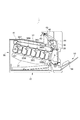
まず、本発明の第1の実施の形態について説明する。本発明の実施の形態に係るプリンタ1(画像形成装置)は、4色のトナー像を形成する電子写真方式のレーザビームプリンタである。プリンタ1は、図1に示すように、シートを給送するカセット給送部10及び手差し給送部50と、シートに転写する画像を形成する画像形成部30と、を有している。
First Embodiment
First, a first embodiment of the present invention will be described. The printer 1 (image forming apparatus) according to the embodiment of the present invention is an electrophotographic laser beam printer that forms toner images of four colors. As shown in FIG. 1, the
プリンタ1に画像形成の指令が出力されると、プリンタ1に接続された外部のコンピュータ等から入力された画像情報に基づいて、画像形成部30による画像形成プロセスが開始される。画像形成部30は、スキャナユニット31と、イエロー(Y)、マゼンタ(M)、シアン(C)及びブラック(Bk)の4色の画像を形成する4つのプロセスカートリッジ32Y,32M,32C,32Bkと、を備えている。なお、4つのプロセスカートリッジ32Y,32M,32C,32Bkは、形成する画像の色が異なること以外は同じ構成であり、プロセスカートリッジ32Yの画像形成プロセスのみを説明し、プロセスカートリッジ32M,32C,32Bkの説明は省略する。
When an image formation command is output to the
スキャナユニット31は、入力された画像情報に基づいて、プロセスカートリッジ32Yの感光ドラム33に向けてレーザ光を照射する。このとき感光ドラム33は、不図示の帯電ローラにより予め帯電されており、レーザ光が照射されることで感光ドラム33上に静電潜像が形成される。その後、現像ローラ35によりこの静電潜像が現像され、感光ドラム33上にイエロー(Y)のトナー像が形成される。
The
同様にして、プロセスカートリッジ32M,32C,32Bkの感光ドラム上にも、マゼンタ(M)、シアン(C)及びブラック(Bk)のトナー像が形成される。各感光ドラム上に形成された各色のトナー像は、一次転写ローラ36Y,36M,36C,36Bkにより中間転写ベルト37に転写され、M方向に回転する中間転写ベルト37により二次転写ローラ38まで搬送される。なお、各色の画像形成プロセスは、中間転写ベルト37上に一次転写された上流のトナー像に重ね合わせるタイミングで行われる。
Similarly, toner images of magenta (M), cyan (C) and black (Bk) are formed on the photosensitive drums of the
上述の画像形成動作に並行して、カセット給送部10に収納されたシート又は手差し給送部50に積載されたシートが、1枚ずつレジストレーションローラ15に向けて給送される。そして、レジストレーションローラ15により所定の搬送タイミングで搬送されたシートには、二次転写ローラ38によって、中間転写ベルト37上のトナー像が転写される。トナー像が転写されたシートは、定着部39でトナー像が定着され、排出ローラ対40により排出トレイ41上に排出される。
In parallel with the above-described image forming operation, the sheets stored in the
シートの両面に画像を形成する場合には、二次転写ローラ38によって第1面に画像が形成されたシートは、切換え部材42によって反転ローラ対43に向けて案内されて、反転ローラ対43によって反転された後に両面搬送路44に案内される。そして、このシートは、レジストレーションローラ15へと再度搬送されて、二次転写ローラ38によって第2面に画像が形成され、排出トレイ41上に排出される。
When forming an image on both sides of the sheet, the sheet on which the image is formed on the first side by the
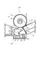
次に、シート搬送装置としての手差し給送部50について、図2、図3及び図4に沿って説明する。手差し給送部50は、シートS若しくはシート束Saを積載可能なシートトレイ51と、固定部材である給紙フレーム52(フレーム部材)に回転可能に支持されたフィードローラ53(回転体)及び搬送ローラ対55と、を有している。また、手差し給送部50は、不図示のトルクリミッタを内蔵した分離ローラ54(分離部材)を有している。シートトレイ51には、給送方向下流側が昇降可能となるように、中板56(積載部)が回動可能に支持されている。中板56は、フィードローラ53に当接してシート束Saの最上位のシートSが給送可能となるように、中板ばね57によってフィードローラ53に向けて付勢されている。
Next, the manual
また、中板56は、積載されたシートが1枚給送される毎に追加してシートを積載できるように、シートの給送が終わる度にフィードローラ53に対して、シート積載上限高さ以上離れて配置される必要がある。そのため、図4に示すように、フィードローラ53を回転可能に支持するフィードローラ軸53cには、昇降カム58,58が固定されており、中板56には、昇降カム58,58に摺動可能なカムフォロワ56a,56aが形成されている。フィードローラ軸53cの軸端部には、フィードローラギヤ59が取付けられており、フィードローラギヤ59の駆動伝達経路上流には、不図示のクラッチが取付けられている。そして、このクラッチによって、不図示の駆動源からフィードローラ53へ伝達される動力が断接される。
In addition, the
すなわち、フィードローラ53が待機状態においては、昇降カム58,58によって中板56のカムフォロワ56a,56aが押し下げられており、シートを中板56上に積載可能な状態になっている。クラッチがONされてフィードローラ軸53cが回転すると、カムフォロワ56a,56aが昇降カム58,58に摺動しつつ、中板ばね57によって、中板56が上昇する。そして、中板56に積載されたシート束Saの最上位のシートSがフィードローラ53に当接し、シートSがフィードローラ53によって給送される。フィードローラ53が1回転すると、シートSは給送方向下流の搬送ローラ対55,55によって搬送され、中板56は昇降カム58,58によって再度押し下げられた状態となる。
That is, when the
ここで、フィードローラ53が1回転し、シートSが搬送ローラ対55,55によって搬送される際には、停止しているフィードローラ53とシートSとが摺動して、フィードローラ53の外周面を覆うフィードローラゴム53aが偏摩耗してしまう。そのため、フィードローラ53は、Dカット形状に形成されたフィードローラゴム53aと、フィードローラゴム53aの軸方向両端部に配置され、回転自在に支持されたフィードローラコロ53b、53bと、を有している。フィードローラコロ53b、53bは、フィードローラゴム53aよりも外径が小さく形成されており、フィードローラゴム53aがDカットされた部分のみ、フィードローラゴム53aよりも外径方向に突出している。
Here, when the
また、フィードローラ53は、待機状態においては、フィードローラコロ53b、53bがシートSと当接する位置で待機しており、搬送ローラ対55,55によってシートSが搬送される際には、シートSとフィードローラゴム53aは摺動しない。したがって、フィードローラゴム53aが偏摩耗することを防止して、フィードローラ53を長寿命化することができる。
Further, in the standby state, the
図2に示すように、給紙フレーム52には、回動支点60aを中心に分離ローラホルダ60(保持部材)が回動可能に支持されており、分離ローラホルダ60は、分離ローラ54を回転可能に保持している。分離ローラホルダ60は、分離バネ61(第1付勢部材)によって上方に付勢されており、これにより分離ローラ54が所定の接触圧でフィードローラ53に接触し、分離ニップN(接触部)を形成している。分離バネ61は、分離ローラホルダ60と給紙フレーム52の底板52bとの間に縮設されている。フィードローラ53によって給送されたシートSは、分離ニップNによって1枚ずつに分離されて搬送ローラ対55へと搬送される。
As shown in FIG. 2, the separation roller holder 60 (holding member) is rotatably supported by the
中板56に積載されたシート束Saと分離ニップNとの間には、ニップガイド63(ガイド部材)が配置されており、ニップガイド63は、回動支点63aを中心に、分離ローラホルダ60に回動可能に支持されている。ニップガイド63の上面には、シートSを分離ニップNに滑らかに案内可能な先端ガイド63b(押圧面)が形成されており、ニップガイド63の右側面には、シートSの先端が接触するガイド面63c(当接面)が形成されている。
A nip guide 63 (guide member) is disposed between the sheet bundle Sa stacked on the
ニップガイド63は、ニップガイドバネ64(第2付勢部材)によって上方に付勢されており、分離ローラホルダ60に設けられたストッパ65(規制部)に当接した当接位置で位置決めされている。ニップガイドバネ64は、ニップガイド63と分離ローラホルダ60との間に縮設されている。そして、ニップガイド63が当接位置にある状態では、先端ガイド63bとフィードローラ53の外周面は、所定距離hだけ離間している。ニップガイド63の右側面には、上記ガイド面63cと、ガイド面63cの下方に形成されるシート非接触面63dと、が形成されている(図5参照)。給紙フレーム52は、シート非接触面63dにシートが当接しないように、突き当て面52aによってシート非接触面63dを覆うように折曲されている。
The nip guide 63 is urged upward by the nip guide spring 64 (second urging member), and is positioned at an abutting position in contact with a stopper 65 (regulating portion) provided on the
すなわち、シート非接触面63dは、中板56に積載されたシートがシート非接触面63dに接触することで、図2におけるニップガイド63が時計回りに回動するように形成されている。ニップガイド63が時計回りに回動すると、所定距離hよりも厚いシート束が分離ニップNに突入し易くなってしまう。そのため、本実施の形態では、給紙フレーム52に突き当て面52aを形成することで、シート非接触面63dにシートが当接することを規制して、所定距離hよりも厚いシート束が分離ニップNに突入し難いように構成されている。これにより、シートの端部が損傷することを防止すると共に、シートの分離性能を向上することができる。また、突き当て面52aは、中板56に積載されたシート束Saと略直角に当接するように形成されており、中板56が昇降する際にシート束Saにダメージを与えないようになっている。なお、ニップガイド63のガイド面63cにシートが当接した際には、図2におけるニップガイド63が反時計回りに回動するように、ニップガイド63に対して力が作用する。
That is, the sheet
次に、手差し給送部50の一連の動作について、図5乃至図13を用いて説明する。シートトレイ51にシート束Saが積載され、プリンタ1から給送信号が送られると、不図示の駆動源が駆動し、不図示のクラッチが所定の給送タイミングに従ってONされる。これにより、中板56が上昇してシート束Saがフィードローラ53に当接し、フィードローラ53が図5において時計回りに回転することで、シート束Saの最上位のシートSが分離ニップNに向かって搬送され始める。
Next, a series of operations of the
ここで、フィードローラ53によりシート束SaのシートSが1枚給送される場合と、複数枚給送される場合とのそれぞれについて、図5乃至図7を用いて説明する。まず、シートSが1枚ずつ給送される場合には、図5に示すように、シートSは、フィードローラ53と先端ガイド63bとの間を通過して分離ニップNに向けて搬送される。最上位のシートS以外のシート束Saは、最上位のシートSがフィードローラ53により分離ニップNへの搬送力を受けると、シート同士の摩擦によってガイド面63cに接触して押圧力が生じる。
Here, the case where one sheet S of the sheet bundle Sa is fed by the
そのため、ニップガイド63は、ガイド面63cにおいて矢印Q方向に押圧力を受け、回動支点63aを支点として反時計回り方向に回動しようとするが、ストッパ65によって反時計回り方向(フィードローラ53に近づく方向)の回動が規制される。これにより、ニップガイド63は、ストッパ65に当接する当接位置が維持される。
Therefore, the
よって、薄紙や厚紙といった剛性の異なる多種多様なシートが給送されても、ニップガイド63の姿勢は変化せず、ニップガイド63の先端ガイド63bがフィードローラ53から離間して、シートSの先端と分離ローラ54との当接角が大きくなることもない。これにより、シートSの先端と分離ローラ54との当接角が大きな状態でシートSの先端が分離ローラ54に衝突することが無く、シートSの先端へのダメージを軽減することができる。また、分離ローラ54にシートSが突き刺さってジャムが発生することを防止することができる。
Therefore, even if a wide variety of sheets with different rigidity such as thin paper and thick paper are fed, the posture of the
そして、1枚のシートSが分離ニップNに給送された場合には、フィードローラ53と分離ローラ54の間の摩擦力により、分離ローラ54に内蔵された不図示のトルクリミッタが空転する。これにより、分離ローラ54は、シート給送方向に搬送されるシートSに従動回転して、シートSは下流側へ搬送される。
Then, when one sheet S is fed to the separation nip N, a torque limiter (not shown) incorporated in the
次いで、複数枚のシートSがフィードローラ53によって束となって給送される場合について説明するが、以下の2つの場合がある。
Next, a case where a plurality of sheets S are fed in a bundle by the
1つ目は、図6に示すように、シート束Saの上部の数枚が、ガイド面63cを乗り越えて分離ニップNに搬送される場合である。つまり、先端ガイド63bとフィードローラ53の外周面との所定距離hよりも、ガイド面63cを乗り越えた数枚のシートSの厚みが小さい場合(t<h)である。
The first case is a case where several sheets of the upper part of the sheet bundle Sa are transported to the separation nip N over the
この場合、1枚のシートSが分離ニップNに給送された場合と同様に、ニップガイド63は、ガイド面63cにおいて矢印Q(シート搬送方向)の方向に押圧力を受け、反時計回り方向に回動しようとするが、ストッパ65によってその回動が規制される。そして、ガイド面63cを乗り越えた数枚のシートSは、フィードローラ53と先端ガイド63bとの間を通過して分離ニップNに搬送される。この時、不図示のトルクリミッタの負荷に対してシートS間の摩擦力が小さいことから、分離ローラ54は回転せず、分離ニップNにおいて数枚のシートSを1枚ずつ分離することができる。これにより、中板56から給送された数枚のシートのうち、最上位のシートSのみが搬送方向下流側に搬送され、それ以外のシートは、停止している分離ローラ54によって止められて分離ニップNにとどまる。
In this case, as in the case where one sheet S is fed to the separation nip N, the
2つ目は、図7に示すように、ガイド面63cを乗り越えた複数枚のシートSの厚みtが所定距離h以上の場合(t≧h)である。この場合、シートSの束は、先端ガイド63bとフィードローラ53との間に挟み込まれる。すると、ニップガイド63には、先端ガイド63bにおいて、シートSの束を挟み込む挟持力の反力が矢印R方向に作用する。そして、ニップガイド63は、矢印R方向の反力によって、ニップガイドバネ64の付勢力に抗して、回動支点63aを中心に時計回り(フィードローラ53から離れる方向)に回動する。
The second case is a case where the thickness t of the plurality of sheets S which get over the
このようにニップガイド63が時計回りに回動すると、ニップガイド63とフィードローラ53によるシートSの束への挟持力は、ニップガイドバネ64の付勢力によって生じる力のみとなる。その結果、シートSの束への挟持力は低減する。この状態でシートSの束が分離ニップNに到達した場合、不図示のトルクリミッタの負荷に対してシートS間の摩擦力が小さいために、分離ローラ54は回転せず、シートSの束を捌くことができる。そして、シートSの束のうち、最上位の1枚のシートのみがシート搬送方向下流側に搬送される。
As described above, when the
このように、シートSの束がニップガイド63の先端ガイド63bとフィードローラ53との間に挟み込まれた時に、ニップガイド63が時計回りに回動するためには、ニップガイド63の回動支点63aは、図8に示すような位置に位置決めされている。すなわち、回動支点63aは、ガイド面63cのフィードローラ53から最も近い側の端部63fを通り、ガイド面63cに垂直な第1直線Aに対してフィードローラ53から遠い側に配置される。また、回動支点63aは、先端ガイド63bのシート搬送方向における下流端63eを通り、分離ニップNの法線に平行な第2直線Bに対して分離ニップNに近い側に配置されている。このように、第1直線Aに対してフィードローラ53から遠い側であって、かつ第2直線Bに対して分離ニップNに近い側である領域(図の斜線部分)を領域Cとする。
Thus, when the bundle of sheets S is nipped between the
ここで、比較例として、ニップガイド63の回動支点63aが領域Cに配置されない構成について、図9を用いて説明する。なお、この比較例では、本実施の形態と同じ構成については、図面に同一の符号を付して、説明を省略する。まず、図9(a)に示すように、第1直線Aに対してフィードローラ53側にニップガイド163の回動支点163aを配置した場合について説明する。
Here, as a comparative example, a configuration in which the
このような場合では、ガイド面163bに接触したシート束Saの矢印U方向の押圧力により、ニップガイド163が時計回りに回動する。すると、先端ガイド163cとフィードローラ53との所定距離hが広がって、ガイド面163bを乗り越えて分離ローラ54に当接したシートSの先端と分離ローラ54の周面との当接角が急激に大きくなる。分離ローラ54の周面は、摩擦係数が大きく設定されているため、当接角が大きな状態でシートSの先端と分離ローラ54とが衝突すると、シートの先端に大きなダメージが発生したり、ジャムが発生したりしてしまう。
In such a case, the pressing force of the sheet bundle Sa in contact with the
次いで、図9(b)に示すように、第2直線Bに対して分離ニップN側にニップガイド263の回動支点263aを配置した場合について説明する。このような場合では、ニップガイド263の先端ガイド263bとフィードローラ53との間に所定距離h以上の厚みのシートSの束が挟み込まれると、ニップガイド263が反時計回りに回動しようとする。すると、シートSの束の挟持圧が大きくなって、先端ガイド263bとフィードローラ53との間で搬送力が発生する。この搬送力が過大になると、複数枚のシートSが分離ニップNを超えて搬送されてしまい、シートが重送されることとなり、ジャムが発生する。
Next, as shown in FIG. 9B, the case where the
したがって、本実施の形態では、領域Cにニップガイド63の回動支点63aを配置することで、ニップガイド63のガイド面63cに対してシート束Saからの押圧力が作用して、ニップガイド63は反時計回りに回動しようとする。しかし、ストッパ65によってニップガイド63は当接位置で位置決めされるため、搬送されるシートSの先端と分離ローラ54の周面との当接角が大きな状態でシートの先端が分離部材に衝突することが無い。これにより、シートの先端へのダメージを軽減することができ、分離部材にシートが突き刺さってジャムが発生することを防止することができる。
Therefore, in the present embodiment, by disposing the
また、ニップガイド63の先端ガイド63bとフィードローラ53との間に所定距離h以上の厚みのシートSの束が挟み込まれると、ニップガイド63は、ニップガイドバネ64の付勢力に抗して、時計回りに回動する。この際、分離ローラホルダ60と給紙フレーム52の底板52b(図2参照)との間に縮設された分離バネ61の付勢力は、分離ローラホルダ60とニップガイド63との間に縮設されたニップガイドバネ64の付勢力よりも十分大きく設定されている。そのため、ニップガイド63が時計回りに回動しても、分離ローラホルダ60は、ニップガイド63と共に回動することはない。これにより、分離ローラ54がフィードローラ53を押圧した状態が維持されるので、シートを確実に1枚ずつ分離することができる。また、ニップガイド63の先端ガイド63bとフィードローラ53との間にシートSの束が詰まって、ジャムが発生することを防止することができる。
Further, when a bundle of sheets S having a thickness equal to or greater than a predetermined distance h is nipped between the
また、本実施の形態では、ニップガイド63の回動支点63aと、ストッパ65と、を分離ローラホルダ60に設けている。これは、フィードローラ53が、互いに外径の異なるフィードローラゴム53a及びフィードローラコロ53bから構成され、フィードローラ53が1回転する際に分離ローラ54と接触している部分の直径が変化するためである。
Further, in the present embodiment, the
ここで、比較例として、ニップガイドの回動支点と、ストッパと、を給紙フレーム52に設け、これらを回動支点463a、ストッパ465とした場合について、図10を用いて説明する。なお、この比較例では、本実施の形態と同じ構成については、図面に同一の符号を付して、説明を省略する。
Here, as a comparative example, the case where the rotation support point of the nip guide and the stopper are provided on the
フィードローラコロ53bと先端ガイド63bが対向する際には、図10(a)に示すように、フィードローラ53と先端ガイド63bは所定距離h1離れている。フィードローラゴム53aと先端ガイド63bが対向する際には、図10(b)に示すように、フィードローラ53と先端ガイド63bは所定距離h2離れている。したがって、中板56に積載されたシートSを給送するためにフィードローラ53が1回転すると、フィードローラ53と先端ガイド63bとの距離は、待機時には所定距離h1であるが、給送時には所定距離h2に変化する。
When the
また、フィードローラが1回転すると、分離ニップNにおいてフィードローラ53の直径が変化するために、分離ローラ54及び分離ローラホルダ60は、フィードローラ53の直径に応じて回動する。この分離ローラ54及び分離ローラホルダ60の回動は、シートSが分離ニップNに到達する前に行われる。しかし、この比較例では、回動支点463a及びストッパ465を給紙フレーム52に設けたために、分離ローラホルダ60が回動しても、ニップガイド63が分離ローラホルダ60に追従しない。
In addition, when the feed roller makes one rotation, the diameter of the
図10(c)及び図10(d)に示すように、ガイド面63cを乗り越えたシートSの厚みtが所定距離h1と同じ場合(t=h1)、フィードローラ53が1回転すると、所定距離h1から所定距離h2に変化した分だけ、ニップガイド63が回動する。すると、シートSの先端と分離ローラ54の周面との当接角αが急激に大きくなる。分離ローラ54の周面は、摩擦係数が大きく設定されているため、当接角αが大きな状態でシートSの先端と分離ローラ54とが衝突すると、シートの先端に大きなダメージが発生したり、ジャムが発生したりしてしまう。
As shown in FIGS. 10 (c) and 10 (d), when the thickness t of the sheet S having passed over the
そのため、本実施の形態では、図11に示すように、ニップガイド63の回動支点63aと、ストッパ65と、を分離ローラホルダ60に設け、分離ローラホルダ60が回動すると、ニップガイド63が分離ローラホルダ60に追従するように構成している。すなわち、分離ニップNにおいてフィードローラ53の直径が変化し、分離ローラ54及び分離ローラホルダ60が回動しても、フィードローラ53と先端ガイド63bとの距離は、常に所定距離h1となる。これは、フィードローラゴム53aと先端ガイド63bとの間に挟まれたシートSの束によってニップガイド63が回動する前に、分離ローラ54及び分離ローラホルダ60がフィードローラゴム53aによって押し下げられるためである。これにより、シートSの先端と分離ローラ54の周面との当接角βが大きくなることはなく、シートの先端のダメージを低減し、ジャムの発生を防止することができる。
Therefore, in the present embodiment, as shown in FIG. 11, when the
なお、本実施形態においては、フィードローラゴム53aによって分離ローラ54が押し下げられる構成としているが、フィードローラゴム53aの回転方向上流に、摩擦係数の低いテーパ面を形成し、該テーパ面によって分離ローラ54を押し下げてもよい。これにより、シートSが分離ニップNに到達する前に、確実に分離ローラ54及び分離ローラホルダ60を押し下げることができ、シートSの先端にダメージが発生することを防止することができる。
In this embodiment, the
また、ガイド面63cは、ニップガイド63がストッパ65に当接した状態で、中板56に積載されたシート束Saと略直角に当接するように形成されている。言い換えれば、ガイド面63cは、シート搬送方向と略直交する方向に沿って形成されている。これにより、分離ローラホルダ60が回動してニップガイド63が追従する際に、ガイド面63cがシート束Saと摺動することに起因してシート束Saの先端にダメージを与えることを防止することができる。なお、略直角又は略直交とは、必ずしも90°でなくてもよく、例えば80°〜100°でもよい。
Further, the
また、先端ガイド63bは、ニップガイド63がストッパ65に当接した状態で、中板56に積載されたシート束Saと略平行となるように形成されている。言い換えれば、先端ガイド63bは、シート搬送方向と略平行に形成されている。そのため、先端ガイド63bとフィードローラ53との間に挟み込まれたシートSの束から先端ガイド63bに作用する挟持力の反力は、先端ガイド63bの全面に亘ってバランスよく作用する。これにより、ニップガイド63を滑らかに回動することができると共に、シートSの表面の一部に力が集中してシートSの表面にダメージを与えることを防止することができる。
Further, the
なお、略平行とは、必ずしも先端ガイド63bとシート束Saとのなす角が0°にならなくてもよく、例えばシート搬送方向下流に向かって分離ニップNに近づくように若干の傾斜をつけることで、シートSを滑らかに分離ニップNに案内するようにしてもよい。
The term “substantially parallel” does not necessarily mean that the angle formed between the
次に、分離ローラホルダ60の回動支点60aの位置について、図12を用いて説明する。回動支点60aは、図12(a)に示すように、ガイド面63cのフィードローラ53から最も遠い側の端部Pを通り、中板56に積載可能な上限高さのシート束Sa1の表面に平行な第3直線Dに対して、フィードローラ53に近い側に配置されている。また、回動支点60aは、第4直線Eに対して、フィードローラ53から遠い側に配置されている。第4直線Eとは、ガイド面63cのフィードローラ53から最も近い側の端部63fを通り、中板56に積載されてフィードローラ53に当接した状態の所定厚さ以下のシート束Sa2の表面に平行な直線である。所定厚さ以下のシート束Sa2は、例えば2,3枚のシート束でもよい。
Next, the position of the
更に、回動支点60aは、分離ニップNの法線G、すなわち分離ニップNにおけるフィードローラ53及び分離ローラ54の接線に垂直な線よりも、シート搬送方向における下流側に配置されている。このように、第3直線Dに対してフィードローラ53に近い側、第4直線Eに対してフィードローラ53から遠い側、かつ法線Gよりシート搬送方向における下流側である領域(図の斜線部分)を領域Fとする。
Further, the
本実施の形態では、領域F内に分離ローラホルダ60の回動支点60aを配置したので、シート給送時にシート束Sa1又はシート束Sa2からガイド面63cに作用する矢印Q方向の押圧力は、おおよそ回動支点60aに向けて作用する。そのため、ストッパ65によって移動規制されたニップガイド63を介して、分離ローラホルダ60に作用するこの押圧力は、分離ローラホルダ60の回転モーメントとしては作用しない。これにより、中板56に積載されたシート束Saの厚さが変動したとしても、シート給送時の分離ニップNの接触圧(分離圧)は変化せず、安定してシートSを1枚ずつに分離することができる。
In the present embodiment, since the
以上のように、本実施の形態では、剛性の異なる多種多様なシートSがニップガイド63のガイド面63cに突入した時に、シートSが束であっても1枚であってもニップガイド63は回動せず、シートの先端を傷つけずに分離ニップNに案内することができる。
As described above, in the present embodiment, when various types of sheets S having different rigidity rush into the
また、シートSの束がニップガイド63の先端ガイド63bとフィードローラ53との間に挟み込まれた時は、ニップガイド63がフィードローラ53から離れる方向に回動する。この際、分離ローラホルダ60はニップガイド63と共に回動することはなく、分離ローラ54がフィードローラ53を押圧した状態は維持される。これにより、シートSが重送されることを防止して、ジャムの発生を防止することができる。
When the bundle of sheets S is nipped between the
従って、プリンタ等の画像形成装置の高速化、小型化、使用されるメディアの多様化に対して、シートSにダメージを与えず、シートSを1枚ずつ確実に分離して、画像形成部30に搬送することができる。 Therefore, the sheet S is reliably separated one by one without damaging the sheet S with respect to speeding up, downsizing, and diversification of media used for the image forming apparatus such as a printer, and the like. Can be transported to
(第2の実施の形態)
次に、本発明の第2の実施の形態について説明するが、上述した第1の実施の形態と同じ構成については、図面に同一の符号を付して、説明を省略する。シート給送装置650のニップガイド63は、図13に示すように、ニップガイドバネ664によってフィードローラ53に向けて付勢されている。ニップガイドバネ664は、ニップガイド63と給紙フレーム52の底板52bとの間に縮設されている。
Second Embodiment
Next, a second embodiment of the present invention will be described. The same reference numerals as in the above-described first embodiment denote the same parts as in the first embodiment, and a description thereof will be omitted. The nip guide 63 of the
これにより、ニップガイド63が、ニップガイドバネ664の付勢力に抗して時計回りに回転する際に、分離ローラホルダ60には力がほとんど作用しない。そのため、ニップガイドバネ664及び分離バネ61の設計自由度を向上することができる。
Thus, when the
なお、上述の2つの実施形態においては、ストッパ65は、分離ローラホルダ60と一体に構成されてもよく、別部材を分離ローラホルダ60に固定してもよい。また、ストッパ65を分離ローラホルダ60以外の部材に固定してもよい。
In the two embodiments described above, the
また、上述の2つの実施形態においては、フィードローラ53及び分離ローラ54を備えた手差し給送部50を例に挙げて説明したが、以下のような給送方式によっても、同様の効果が得られる。例えば、ピックアップローラによってシートの給送を行い、フィードローラ及び分離ローラによってシートを1枚ずつに分離するものでもよい。例えば、分離ローラの代わりに、給送方向と逆の回転方向に回転するリタードローラ(分離部材)を用いたものや、分離パッド(分離部材)等の非回転体を用いてシートを1枚ずつに分離するものでもよい。
Further, in the above two embodiments, the
また、本発明は、手差し給送部だけでなく、カセット式のカセット給送部に適用してもよい。また、昇降可能な中板を備えずに、シートトレイに直接シートを積載するシート給送装置に適用してもよい。 The present invention may be applied not only to the manual feed unit but also to a cassette type cassette feed unit. Further, the present invention may be applied to a sheet feeding apparatus which directly stacks sheets on a sheet tray without providing an up-and-down movable middle plate.
1:画像形成装置(プリンタ)、30:画像形成部、50:シート搬送装置(手差し給送部)、52:フレーム部材(給紙フレーム)、52b:フレーム部材(底板)、53:回転体(フィードローラ)、54:分離部材(分離ローラ)、56:積載部(中板)、60:分離ローラホルダ(保持部材)、60a:回動支点、61:第1付勢部材(分離バネ)、63:ガイド部材(ニップガイド)、63a:回動支点、63b:押圧面(先端ガイド)、63c:当接面(ガイド面)、63e:下流端、63f:端部、64:第2付勢部材(ニップガイドバネ)、65:規制部(ストッパ)、A:第1直線、B:第2直線、D:第3直線、E:第4直線、G:法線、N:接触部(分離ニップ)、S:シート、Sa:シート束、Sa1:上限高さのシート束、Sa2:所定厚さ以下のシート束、Q:シート搬送方向 1: Image forming apparatus (printer), 30: Image forming section, 50: Sheet conveying apparatus (manual feeding section), 52: Frame member (sheet feeding frame), 52b: Frame member (bottom plate), 53: Rotatable body ( Feed roller), 54: separation member (separation roller), 56: stacking portion (middle plate), 60: separation roller holder (holding member), 60a: rotation fulcrum, 61: first biasing member (separation spring), 63: guide member (nip guide), 63a: rotation fulcrum, 63b: pressing surface (tip guide), 63c: abutment surface (guide surface), 63e: downstream end, 63f: end, 64: second biasing Member (nip guide spring), 65: restriction part (stopper), A: first straight line, B: second straight line, D: third straight line, E: fourth straight line, G: normal, N: contact part (separate Nip), S: sheet, Sa: sheet bundle, Sa1: upper limit of height Over sheet bundle, Sa2: predetermined thickness less the sheet bundle, Q: the sheet conveying direction
Claims (12)
前記積載部に積載されたシートに接触した状態で回転することで、シートを搬送する回転体と、
前記回転体に向けて押圧され、前記回転体との接触部でシートを1枚ずつ分離する分離部材と、
前記分離部材を保持する保持部材と、
前記保持部材に対して回動可能に設けられ、前記接触部にシートの先端を案内可能なガイド部材と、
前記ガイド部材に当接して、前記ガイド部材が前記回転体に近づく方向に回動することを規制する規制部と、を備え、
前記ガイド部材は、前記積載部に積載されたシートに当接する当接面と、前記当接面と別の位置で前記回転体と前記ガイド部材との間に搬送されたシート束が当接する押圧面と、を有し、前記押圧面が前記シート束に押圧されることによって、前記回転体から離れる方向に前記保持部材に対して回動し、
前記保持部材に対して前記ガイド部材が回動する回動支点は、前記当接面の前記回転体から最も近い側の端部を通り、前記当接面に垂直な第1直線に対して前記回転体から遠い側であって、かつ前記押圧面のシート搬送方向における下流端を通り、前記接触部の法線に平行な第2直線に対して前記接触部に近い側に配置される、
ことを特徴とするシート搬送装置。 A loading unit on which sheets are loaded;
A rotating body for conveying the sheet by rotating in a state of being in contact with the sheet stacked on the stacking unit;
A separation member which is pressed toward the rotating body and separates the sheets one by one at a contact portion with the rotating body;
A holding member for holding the separation member;
A guide member provided rotatably with respect to the holding member and capable of guiding the front end of the sheet to the contact portion;
And a restricting portion that abuts on the guide member and restricts rotation of the guide member in a direction approaching the rotating body.
The guide member is a pressing surface against which the sheet bundle conveyed between the rotating body and the guide member abuts at a position different from the contact surface that abuts against the sheets stacked on the stacking unit and the contact surface has a face, and by the pressing surface is pressed against the sheet bundle, pivoted relative to the holding member in a direction away from said rotary member,
The pivot point on which the guide member pivots with respect to the holding member passes the end portion of the contact surface closest to the rotary body, and the first straight line is perpendicular to the contact surface. It is disposed on the side far from the rotating body, and on the side closer to the contact portion with respect to a second straight line parallel to the normal to the contact portion, passing through the downstream end of the pressing surface in the sheet conveying direction.
Sheet conveying apparatus characterized in that.
請求項1記載のシート搬送装置。 Said guide member, prior Symbol forces in the sheet conveyance direction in the abutment surface is by acting, it is pressed against the regulating unit,
Claim 1 Symbol placement of the sheet conveying device.
請求項1又は2に記載のシート搬送装置。 The guide member, by the previous SL pressing surface is pressed against the sheet bundle, is rotated in a direction away from said rotary member,
The sheet conveying apparatus according to claim 1 .
請求項1から3のいずれか1項に記載のシート搬送装置。 The restricting portion is provided on the holding member.
The sheet conveying apparatus according to any one of claims 1 to 3 .
請求項4に記載のシート搬送装置。 The rotation supporting point at which the holding member rotates is a third end of the contact surface that is farthest from the rotating body and is parallel to the surface of the sheet bundle of the upper limit height that can be loaded on the loading unit. A predetermined thickness of a state of being loaded on the loading portion and in contact with the rotating body, passing an end portion on the side closer to the rotating body with respect to a straight line and on the side closest to the rotating body of the contact surface It is disposed on a side far from the rotating body with respect to a fourth straight line parallel to the surface of the sheet bundle having a size smaller than that, and on the downstream side in the sheet conveying direction from the normal line of the contact portion.
The sheet conveying apparatus according to claim 4 .
請求項1から5のいずれか1項に記載のシート搬送装置。 The contact surface is formed along a direction substantially orthogonal to the sheet conveyance direction in a state where the guide member contacts the restriction portion.
The sheet conveying apparatus according to any one of claims 1 to 5 .
請求項1から6のいずれか1項に記載のシート搬送装置。 The pressing surface is formed substantially in parallel with the sheet conveying direction in a state where the guide member is in contact with the regulating portion.
The sheet conveying apparatus according to any one of claims 1 to 6 .
前記ガイド部材は、前記保持部材及び前記分離部材を前記シート搬送方向に直交する幅方向における外側から覆い、かつ前記シート搬送方向における前記分離部材の下流端よりも上流に配置されている、 The guide member covers the holding member and the separating member from the outside in the width direction orthogonal to the sheet conveying direction, and is disposed upstream of the downstream end of the separating member in the sheet conveying direction.
請求項1から7のいずれか1項に記載のシート搬送装置。 The sheet conveying apparatus according to any one of claims 1 to 7.
前記分離部材を前記回転体に押圧するように前記保持部材を付勢する第1付勢部材と、
前記ガイド部材を前記回転体に向けて付勢する第2付勢部材と、を備え、
前記ガイド部材が、前記第2付勢部材の付勢力に抗して、前記回転体から離れる方向に回動する際には、前記分離部材は、前記第1付勢部材によって前記回転体を押圧した状態が維持される、
請求項1から7のいずれか1項に記載のシート搬送装置。 The holding member is rotatably supported by the frame member,
A first biasing member biasing the holding member to press the separating member against the rotating body;
And a second biasing member for biasing the guide member toward the rotating body,
When the guide member rotates in a direction away from the rotating body against the biasing force of the second biasing member, the separation member presses the rotating body by the first biasing member. Is maintained,
The sheet conveying apparatus according to any one of claims 1 to 7 .
前記第1付勢部材の付勢力は、前記第2付勢部材の付勢力よりも大きい、
請求項9に記載のシート搬送装置。 The second biasing member is contracted between the holding member and the guide member,
The biasing force of the first biasing member is greater than the biasing force of the second biasing member.
The sheet conveying apparatus according to claim 9 .
請求項9に記載のシート搬送装置。 The second biasing member is compressed between the guide member and the frame member.
The sheet conveying apparatus according to claim 9 .
前記シート搬送装置から搬送されたシートに画像を形成する画像形成部と、を備えた、
ことを特徴とする画像形成装置。 A sheet conveying apparatus according to any one of claims 1 to 11.
An image forming unit configured to form an image on a sheet conveyed from the sheet conveying apparatus;
An image forming apparatus characterized by
Priority Applications (2)
| Application Number | Priority Date | Filing Date | Title |
|---|---|---|---|
| JP2014246302A JP6529249B2 (en) | 2014-12-04 | 2014-12-04 | Sheet conveying apparatus and image forming apparatus |
| US14/955,415 US9758324B2 (en) | 2014-12-04 | 2015-12-01 | Sheet conveyance apparatus and image forming apparatus |
Applications Claiming Priority (1)
| Application Number | Priority Date | Filing Date | Title |
|---|---|---|---|
| JP2014246302A JP6529249B2 (en) | 2014-12-04 | 2014-12-04 | Sheet conveying apparatus and image forming apparatus |
Publications (2)
| Publication Number | Publication Date |
|---|---|
| JP2016108079A JP2016108079A (en) | 2016-06-20 |
| JP6529249B2 true JP6529249B2 (en) | 2019-06-12 |
Family
ID=56123249
Family Applications (1)
| Application Number | Title | Priority Date | Filing Date |
|---|---|---|---|
| JP2014246302A Active JP6529249B2 (en) | 2014-12-04 | 2014-12-04 | Sheet conveying apparatus and image forming apparatus |
Country Status (1)
| Country | Link |
|---|---|
| JP (1) | JP6529249B2 (en) |
Families Citing this family (1)
| Publication number | Priority date | Publication date | Assignee | Title |
|---|---|---|---|---|
| JP7404858B2 (en) | 2019-12-23 | 2023-12-26 | コニカミノルタ株式会社 | Sheet stacking device and image forming device |
Family Cites Families (4)
| Publication number | Priority date | Publication date | Assignee | Title |
|---|---|---|---|---|
| JPS61166447A (en) * | 1985-01-18 | 1986-07-28 | Sanyo Electric Co Ltd | Paper feeding device |
| JPS63225044A (en) * | 1987-03-09 | 1988-09-20 | Minolta Camera Co Ltd | Automatic paper feeder |
| JP3870103B2 (en) * | 2002-02-18 | 2007-01-17 | キヤノン株式会社 | Feeding device and recording device |
| JP6157123B2 (en) * | 2013-01-11 | 2017-07-05 | キヤノン株式会社 | Sheet feeding apparatus and image forming apparatus |
-
2014
- 2014-12-04 JP JP2014246302A patent/JP6529249B2/en active Active
Also Published As
| Publication number | Publication date |
|---|---|
| JP2016108079A (en) | 2016-06-20 |
Similar Documents
| Publication | Publication Date | Title |
|---|---|---|
| US9856099B2 (en) | Sheet feeder and image forming apparatus incorporating the sheet feeder | |
| JP6157123B2 (en) | Sheet feeding apparatus and image forming apparatus | |
| US10040652B2 (en) | Sheet feeding apparatus, sheet conveyance apparatus, and image forming apparatus | |
| US9452902B2 (en) | Sheet feeding apparatus and image forming apparatus | |
| JP6545028B2 (en) | Sheet conveying apparatus and image forming apparatus | |
| JP5925162B2 (en) | Sheet feeding apparatus and image forming apparatus | |
| US10183822B2 (en) | Sheet feeding unit, sheet feeding apparatus including sheet feeding unit, and image forming apparatus including sheet feeding apparatus | |
| JP2018108873A (en) | Transport device, medium ejecting device and image forming device | |
| US20170108813A1 (en) | Sheet feeding apparatus and image forming apparatus | |
| US10543996B2 (en) | Sheet feeding apparatus and image forming apparatus | |
| US9758324B2 (en) | Sheet conveyance apparatus and image forming apparatus | |
| JP6529249B2 (en) | Sheet conveying apparatus and image forming apparatus | |
| US8777213B2 (en) | Recording medium storage cassette and image forming apparatus including the same | |
| US11613439B2 (en) | Sheet feeding apparatus and image forming apparatus | |
| US9885988B2 (en) | Sheet conveying apparatus and image forming apparatus including same | |
| JP5139463B2 (en) | Paper feeding device and image forming apparatus | |
| JP6323377B2 (en) | Sheet conveying apparatus and image forming apparatus provided with the same | |
| JP6463105B2 (en) | Sheet conveying apparatus and image forming apparatus | |
| JP4792073B2 (en) | Image forming apparatus | |
| JP2010155681A (en) | Sheet ejecting device and image forming device | |
| JP6686544B2 (en) | Recording medium feeding device and image forming apparatus | |
| JP4569907B2 (en) | Medium conveying apparatus and image forming apparatus | |
| JP7225979B2 (en) | Sheet conveying device, image reading device and image forming device | |
| JP2020040765A (en) | Sheet feeding apparatus and image forming apparatus | |
| JP2006016176A (en) | Paper feeder |
Legal Events
| Date | Code | Title | Description |
|---|---|---|---|
| A621 | Written request for application examination |
Free format text: JAPANESE INTERMEDIATE CODE: A621 Effective date: 20171201 |
|
| A977 | Report on retrieval |
Free format text: JAPANESE INTERMEDIATE CODE: A971007 Effective date: 20180918 |
|
| A131 | Notification of reasons for refusal |
Free format text: JAPANESE INTERMEDIATE CODE: A131 Effective date: 20181002 |
|
| A521 | Written amendment |
Free format text: JAPANESE INTERMEDIATE CODE: A523 Effective date: 20181130 |
|
| TRDD | Decision of grant or rejection written | ||
| A01 | Written decision to grant a patent or to grant a registration (utility model) |
Free format text: JAPANESE INTERMEDIATE CODE: A01 Effective date: 20190416 |
|
| A61 | First payment of annual fees (during grant procedure) |
Free format text: JAPANESE INTERMEDIATE CODE: A61 Effective date: 20190514 |
|
| R151 | Written notification of patent or utility model registration |
Ref document number: 6529249 Country of ref document: JP Free format text: JAPANESE INTERMEDIATE CODE: R151 |