EP2447646A2 - Kühlschrank mit Getränkeausgabereinigungssystem - Google Patents
Kühlschrank mit Getränkeausgabereinigungssystem Download PDFInfo
- Publication number
- EP2447646A2 EP2447646A2 EP20110186550 EP11186550A EP2447646A2 EP 2447646 A2 EP2447646 A2 EP 2447646A2 EP 20110186550 EP20110186550 EP 20110186550 EP 11186550 A EP11186550 A EP 11186550A EP 2447646 A2 EP2447646 A2 EP 2447646A2
- Authority
- EP
- European Patent Office
- Prior art keywords
- fluid
- cleaning
- refrigerator
- line
- beverage
- Prior art date
- Legal status (The legal status is an assumption and is not a legal conclusion. Google has not performed a legal analysis and makes no representation as to the accuracy of the status listed.)
- Withdrawn
Links
- 235000013361 beverage Nutrition 0.000 title claims abstract description 83
- 238000004140 cleaning Methods 0.000 title claims abstract description 82
- 239000012530 fluid Substances 0.000 claims abstract description 113
- 238000000034 method Methods 0.000 claims description 12
- 239000000843 powder Substances 0.000 claims description 6
- 239000006188 syrup Substances 0.000 claims description 6
- 235000020357 syrup Nutrition 0.000 claims description 6
- 238000002156 mixing Methods 0.000 claims description 2
- 238000005086 pumping Methods 0.000 description 16
- 230000000977 initiatory effect Effects 0.000 description 4
- 239000000203 mixture Substances 0.000 description 4
- 238000003825 pressing Methods 0.000 description 4
- XLYOFNOQVPJJNP-UHFFFAOYSA-N water Substances O XLYOFNOQVPJJNP-UHFFFAOYSA-N 0.000 description 3
- 238000011109 contamination Methods 0.000 description 2
- 239000000796 flavoring agent Substances 0.000 description 2
- 235000019634 flavors Nutrition 0.000 description 2
- 238000007792 addition Methods 0.000 description 1
- 230000002411 adverse Effects 0.000 description 1
- 230000001143 conditioned effect Effects 0.000 description 1
- 238000011010 flushing procedure Methods 0.000 description 1
- 239000007788 liquid Substances 0.000 description 1
- 238000012986 modification Methods 0.000 description 1
- 230000004048 modification Effects 0.000 description 1
- 238000006467 substitution reaction Methods 0.000 description 1
Images


Classifications
-
- B—PERFORMING OPERATIONS; TRANSPORTING
- B67—OPENING, CLOSING OR CLEANING BOTTLES, JARS OR SIMILAR CONTAINERS; LIQUID HANDLING
- B67D—DISPENSING, DELIVERING OR TRANSFERRING LIQUIDS, NOT OTHERWISE PROVIDED FOR
- B67D1/00—Apparatus or devices for dispensing beverages on draught
- B67D1/07—Cleaning beverage-dispensing apparatus
-
- F—MECHANICAL ENGINEERING; LIGHTING; HEATING; WEAPONS; BLASTING
- F25—REFRIGERATION OR COOLING; COMBINED HEATING AND REFRIGERATION SYSTEMS; HEAT PUMP SYSTEMS; MANUFACTURE OR STORAGE OF ICE; LIQUEFACTION SOLIDIFICATION OF GASES
- F25D—REFRIGERATORS; COLD ROOMS; ICE-BOXES; COOLING OR FREEZING APPARATUS NOT OTHERWISE PROVIDED FOR
- F25D23/00—General constructional features
- F25D23/12—Arrangements of compartments additional to cooling compartments; Combinations of refrigerators with other equipment, e.g. stove
- F25D23/126—Water cooler
-
- B—PERFORMING OPERATIONS; TRANSPORTING
- B67—OPENING, CLOSING OR CLEANING BOTTLES, JARS OR SIMILAR CONTAINERS; LIQUID HANDLING
- B67D—DISPENSING, DELIVERING OR TRANSFERRING LIQUIDS, NOT OTHERWISE PROVIDED FOR
- B67D1/00—Apparatus or devices for dispensing beverages on draught
- B67D1/08—Details
- B67D1/0857—Cooling arrangements
-
- F—MECHANICAL ENGINEERING; LIGHTING; HEATING; WEAPONS; BLASTING
- F25—REFRIGERATION OR COOLING; COMBINED HEATING AND REFRIGERATION SYSTEMS; HEAT PUMP SYSTEMS; MANUFACTURE OR STORAGE OF ICE; LIQUEFACTION SOLIDIFICATION OF GASES
- F25D—REFRIGERATORS; COLD ROOMS; ICE-BOXES; COOLING OR FREEZING APPARATUS NOT OTHERWISE PROVIDED FOR
- F25D2400/00—General features of, or devices for refrigerators, cold rooms, ice-boxes, or for cooling or freezing apparatus not covered by any other subclass
- F25D2400/22—Cleaning means for refrigerating devices
Definitions
- the present invention generally relates to a beverage dispenser. More particularly, but not exclusively, the present invention relates to a refrigerator beverage dispenser having a cleaning subsystem.
- the background of the invention is discussed in the context of a beverage dispenser used in a refrigerator.
- the present invention is not to be limited to this specific context.
- Refrigerators have long been used to dispense fluid such as water. More recently it has been desirous to provide refrigerators with beverage dispensers.
- One of the problems of dispensing beverages from a refrigerator relates to keeping the beverage dispensing system clean. Failure to keep a beverage dispensing system clean may adversely affect its use. In addition failure to clean may lend to flavor contamination. Yet users may not be willing to take the steps necessary to properly clean a beverage dispenser.
- Another object, feature, or advantage of the present invention is to provide a refrigerator with a beverage dispensing system which is easy and convenient for a user to operate.
- a still further object, feature, or advantage of the present invention is to assist in preventing flavor contamination.
- a refrigerator which includes a cabinet.
- a first compartment and second compartment are disposed within the cabinet.
- a first door provides access to the first compartment and a second door provides access to the second compartment.
- a beverage dispensing system is operatively connected to the cabinet.
- the beverage dispensing system has a fluid line, a fluid enhancement line, and a cleaning subsystem for cleaning the fluid enhancement line and the fluid line.
- a refrigerator has a cabinet with a first compartment and a second compartment disposed within the cabinet.
- a first door provides access to the first compartment and a second door provides access to the second compartment.
- a beverage dispensing system is disposed within the cabinet.
- the beverage dispensing system has fluid lines, syrup or powder lines, and a cleaning subsystem for cleaning out the fluid lines and syrup or powder lines.
- a method of using a refrigerator with a beverage dispensing system includes providing a refrigerator having a refrigerator cabinet and a beverage dispenser operatively connected to the refrigerator cabinet.
- the method further includes receiving an indicia from a user to dispense a beverage.
- the method further includes dispensing the beverage and circulating a cleaning fluid through the fluid line or the fluid enhancement line for cleaning after dispensing.
- Figure 1 is a front elevation view of a refrigerator with a beverage dispenser.
- Figure 2 is a schematic representation of the refrigerator beverage dispenser.
- FIG. 3 is a schematic representation of the refrigerator beverage dispenser cleaning system.
- Figure 4 is a schematic representation of the refrigerator beverage dispenser with a cleaning subsystem.
- Figure 5 is a schematic representation of the refrigerator beverage dispenser with a cleaning subsystem and drain.
- Figure 6 is a schematic representation of the refrigerator beverage dispenser with a permanent cleaning subsystem and drain.
- Figure 7 is a schematic representation of the refrigerator beverage dispenser with a permanent cleaning subsystem.
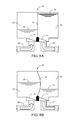
- Figures 8A-B represent a cleaning cartridge for use in a cleaning subsystem of a beverage dispenser.
- FIG 1 illustrates a refrigerator 10 having a fresh food compartment 14 and a freezer compartment 12.
- a fresh food compartment door 18 provides access to the fresh food compartment 14.
- the freezer compartment door 16 provides access to the freezer compartment 12.
- the refrigerator 10 includes a beverage dispensing system 20 which is shown at the door 16.
- the beverage dispenser 20 may include a user interface with control buttons 84 which enable a user to select a preferred dispensing operation. Of course, other types of user interfaces may be provided.
- a first nozzle 90 in the dispenser 20 may deliver a flow of fluid downward.
- a second nozzle 92 adjacent the first nozzle 90 in the dispenser 20 may also deliver a flow of enhanced fluid downward.
- the refrigerator 10 is shown in a side-by-side configuration. Of course, the refrigerator 10 may take on other configurations as well, such as a bottom mount freezer configuration.
- FIG. 2 illustrates a first embodiment which shows the beverage dispenser 20 and associated components for beverage dispensing.
- the beverage dispenser 20 includes a fluid supply 22 and a fluid enhancement component 24.
- the fluid supply 22 is controlled by a valve 36.
- the fluid supply may supply conditioned or unconditioned fluid, such as, unfiltered fluid, filtered fluid, carbonated fluid, uncarbonated fluid, water, or filtered water.
- the fluid lines 34 and 38 provide paths to the beverage mixer 32.
- the fluid enhancement component 24 may be housed within a BIB (bag-in-box), a cartridge, a bottle, or any other type of fluid enhancement container.
- the fluid enhancement component 24 may connect directly into the pump 26 or via the liquid enhancement line 46 or otherwise.
- the fluid enhancement component 24 may be drawn through the pump 26.
- the pump 26 is one component of a pumping mechanism 72.
- the pumping mechanism 72 also may include a motor 28 which actuates the pump 26 and may also be easily separated from the pump 26.
- the pump 26 may be easily removed by a consumer.
- the pump 26 may also be disassembled and cleaned by the consumer either by hand or in a dishwasher.
- the pump 26 may also be attached to a replaceable cartridge and disposed of or returned and cleaned when the cartridge is refilled.
- the fluid supply 22 and the fluid enhancement component 24 are introduced at a beverage mixer 32 via supply lines 38 and 48, respectively.
- the fluid and fluid enhancement may then mix an output to a cup 52 via a beverage mixer line 58.
- the beverage mix line 58 is operatively connected to the nozzle 92, such as shown in Figure 1 .
- the fluid supply valve 36 and the pumping mechanism 72 may be controlled by the control unit 30 in a manner such that a predetermined ratio of the fluid enhancement from the fluid enhancement component 24 to the fluid from the fluid supply 22 is delivered to the beverage mixer 32. Hence, whenever a beverage is requested via the beverage dispenser 20 user interface, the control unit 30 receives this input request and dispenses the selected beverage.
- FIG 3 illustrates another embodiment which shows the beverage dispenser 20 and associated components for beverage dispensing.
- the beverage dispenser 20 includes the fluid supply 22 and the fluid enhancement component 24.
- the fluid supply 22 is controlled by the valve 36.
- the fluid lines 34 and 38 provide a path to the beverage mixer 32.
- the fluid enhancement component 24 may be housed within a BIB (bag-in-box), a cartridge, a bottle, or any other type of fluid enhancement container.
- the fluid enhancement component 24 flows through the pump 26 and the lines 42, 46 respectively via the valve 44.
- the fluid enhancement component 24 may connect directly into valve 44 or via the fluid enhancement line 46.
- the beverage mixing system may utilize a manifold wherein the fluid enhancement component 24, the fluid supply 22, the beverage mixer 32 and the pumping mechanism 72 are interconnected without the use of the various fluid lines.
- the fluid enhancement component 24 is drawn through the pump 26.
- the pump 26 is one component of the pumping mechanism 72.
- Pumping mechanism 72 also has a motor 28 which actuates the pump 26 and also may be easily separated from the pump 26.
- the pump 26 is designed to be easily removable for replacement.
- the fluid supply 22 and the fluid enhancement component 24 are introduced at the beverage mixer 32 via the supply lines 38 and 48 respectively.
- the two fluids are then mixed and output to a cup 52 via a beverage mix line 58.
- the beverage mix line 58 is mated to the nozzle 92, refer to Figure 1 .
- the fluid supply valve 36 and the pumping mechanism 72 may be controlled by the control unit 30 in a manner such that a predetermined ratio of the fluid enhancement to fluid is delivered to the beverage mixer 32.
- the control unit 30 receives this input request and dispenses the selected beverage.
- the pumping mechanism 72, and more specifically the pump 26 is cleaned of residue from the fluid enhancement component 24 by flushing the lines 46, 48 and 58 with a small amount of the fluid from the fluid supply 22.
- the fluid is dispensed into the cup 52 after the initial beverage is mixed. This additional amount of fluid may have a minimum impact on the taste of the mixed beverage.
- fluid supply 22 and fluid enhancement 24 may be delivered directly to cup 52.
- Figure 4 illustrates another embodiment wherein a cleaning cartridge or a cleaning subsystem 50 which may be swapped into the same position as the fluid enhancement 24 as they share the same configuration.
- the pumping mechanism 72, and more specifically the pump 26 may be cleaned of residues from the fluid enhancement component 24 by directing the cleaning solution within the cleaning subsystem 50 through the line 42, the valve 44, and the lines 46 and 48 which are operatively connected to the pump 26.
- the control unit 30 may then direct the fluid supply 22 to flow through the lines 34, 40, 46, 48 and 58 by actuating the valves 36 and 44, and through the pumping mechanism 72 to rinse all the lines and the pump 26 of the cleaning solution.
- the control unit 30 may alert the consumer via the beverage dispenser 20 display 86 when the pump 26 should be cleaned or the consumer may independently initiate a cleaning cycle for the pump 26 by pressing the control button 84 associated with initiating a cleaning cycle. In either example, the consumer may place the cup 52 beneath the beverage dispenser nozzle 92 to collect cleaning solution for disposal.
- Figure 5 illustrates another embodiment wherein a cleaning cartridge or a cleaning subsystem 50 which may be swapped into the same position as the fluid enhancement 24 as they share the same configuration.
- the pumping mechanism 72 and more specifically the pump 26 may be cleaned of residues from the fluid enhancement component 24 by directing the cleaning solution within the cleaning subsystem 50 through the line 42, the valve 44, and the lines 46 and 48 which are operatively connected to the pump 26.
- the control unit 30 may then direct the fluid supply 22 to flow through the lines 34, 40, 46, 48 and 58 by actuating the valves 36 and 44, and through the pumping mechanism 72 to rinse all the lines and the pump 26 of the cleaning solution.
- the control unit 30 may alert the consumer via the beverage dispenser 20 display 86 when the pump 26 should be cleaned or the consumer may independently initiate a cleaning cycle for the pump 26 by pressing the control button 84 associated with initiating a cleaning cycle. In either example, the consumer may place a cup beneath the beverage dispenser nozzle 92 or the consumer may allow the cleaning solution to flow directly into a plumbed drain or a non-plumbed drain 54.
- Figure 6 illustrates another embodiment wherein a cleaning cartridge or a cleaning subsystem 50 is positioned next to the fluid enhancement component 24 instead of being swapped into and out of the same position as the fluid enhancement component 24, refer to Figure 5 .
- the pumping mechanism 72 and more specifically the pump 26 may be cleaned of residues from the fluid enhancement component 24 by directing the cleaning solution within the cleaning subsystem 50 through the line 62, valve 44, line 46, pump 26 and line 48 which feeds beverage mixer 32 and dispenses via line 58.
- the control unit 30 may then direct the fluid within fluid supply 22 to flow through lines 34, 40, 46, 48 and 58 by actuating valves 36 and 44, and pumping mechanism 72 to rinse the lines and pump 26 of the cleaning solution.
- the control unit 30 may alert the consumer via the beverage dispenser display 86 when the pump 26 should be cleaned or the consumer may independently initiate a cleaning cycle for the pump 26 pressing the control button 84 associated with initiating a cleaning cycle.
- the consumer may place the cup 52 beneath the beverage dispenser nozzle 92 to collect cleaning solution for disposal.
- a plumbed or non-plumbed drain 54 may be implemented for removing the cleaning solution as opposed to the cup 52.
- Figure 7 illustrates another embodiment wherein a cleaning cartridge or a cleaning subsystem 70 is positioned next to the fluid enhancement component 24 instead of being swapped into and out of the same position as the fluid enhancement 24, refer to Figure 5 .
- a cleaning subsystem 70 contains the unused cleaning solution 78 and the used cleaning solution 80 which are separated by a flexible divider 82 to form a first chamber 83 and a second chamber 85.
- the cleaning solution 78 from the first chamber 83 enters the beverage dispensing system 20 via a check valve 74 through a line 62.
- the used cleaning solution 80 returns to the second chamber 85 of the cleaning subsystem 70 through the line 68 via a check valve 76.
- the pumping mechanism 72 and more specifically the pump 26 may be cleaned of residue from the fluid enhancement component 24 by directing the cleaning solution 78 within the cleaning subsystem 70 through the line 62, the valve 44, the line 46, the pump 26 and the line 48 which feeds the beverage mixer 32 and continues via the line 64 to the valve 66 which directs the flow path to the line 68 and returns the used cleaning solution 80 to the cleaning subsystem 70.
- the control unit 30 may then direct the fluid within the fluid supply 22 to flow through the lines 34, 40, 46, 48, 64 and 68 by actuating the valves 36, 44, 66 and the pumping mechanism 72 to rinse all the lines and the pump 26 of the cleaning solution 78.
- the flexible divider 82 may be seen extending due to the inflow of used cleaning solution 80 and the fluid rinse within the area vacated by the unused cleaning solution 78, refer to Figure 8B .
- the control unit 30 may alert the consumer via the beverage dispenser display 86 when the pump 26 should be cleaned or the consumer may independently initiate a cleaning cycle for the pump 26 pressing the control button 84 associated with initiating a cleaning cycle.
Landscapes
- Engineering & Computer Science (AREA)
- Chemical & Material Sciences (AREA)
- Combustion & Propulsion (AREA)
- Physics & Mathematics (AREA)
- Mechanical Engineering (AREA)
- Thermal Sciences (AREA)
- General Engineering & Computer Science (AREA)
- Devices For Dispensing Beverages (AREA)
- Beverage Vending Machines With Cups, And Gas Or Electricity Vending Machines (AREA)
Applications Claiming Priority (1)
| Application Number | Priority Date | Filing Date | Title |
|---|---|---|---|
| US12/915,187 US8733595B2 (en) | 2010-10-29 | 2010-10-29 | Refrigerator with beverage dispenser cleaning system |
Publications (1)
| Publication Number | Publication Date |
|---|---|
| EP2447646A2 true EP2447646A2 (de) | 2012-05-02 |
Family
ID=44862688
Family Applications (1)
| Application Number | Title | Priority Date | Filing Date |
|---|---|---|---|
| EP20110186550 Withdrawn EP2447646A2 (de) | 2010-10-29 | 2011-10-25 | Kühlschrank mit Getränkeausgabereinigungssystem |
Country Status (3)
| Country | Link |
|---|---|
| US (2) | US8733595B2 (de) |
| EP (1) | EP2447646A2 (de) |
| BR (1) | BRPI1106813A2 (de) |
Cited By (2)
| Publication number | Priority date | Publication date | Assignee | Title |
|---|---|---|---|---|
| WO2018081117A1 (en) * | 2016-10-25 | 2018-05-03 | Cornelius, Inc. | Systems of food dispenser cleaning |
| CN112179004A (zh) * | 2020-09-14 | 2021-01-05 | 珠海格力电器股份有限公司 | 冷藏柜及其控制方法 |
Families Citing this family (17)
| Publication number | Priority date | Publication date | Assignee | Title |
|---|---|---|---|---|
| IT1401822B1 (it) * | 2010-09-24 | 2013-08-28 | Casadio Prati | Distributore automatico, particolarmente per bevande fredde. |
| CN104411178A (zh) * | 2012-06-28 | 2015-03-11 | 开利公司 | 冷冻食品分配机和操作方法 |
| US10919752B2 (en) * | 2012-12-19 | 2021-02-16 | Michael John Breault | Refrigerator with carbonated drink spout |
| KR102104539B1 (ko) * | 2013-02-28 | 2020-04-27 | 삼성전자주식회사 | 탄산수 제조 장치를 갖춘 냉장고 |
| US9233824B2 (en) | 2013-06-07 | 2016-01-12 | The Coca-Cola Company | Method of making a beverage including a gas in a beverage making machine |
| US9630826B2 (en) | 2013-06-07 | 2017-04-25 | The Coca-Cola Company | Beverage making machine |
| US20170283235A1 (en) * | 2015-07-07 | 2017-10-05 | 87K, Llc | Beverage distribution assembly |
| WO2018191136A1 (en) * | 2017-04-11 | 2018-10-18 | Freshbev Llc | Beverage distribution assembly |
| US9849429B2 (en) | 2015-07-07 | 2017-12-26 | 87K, Llc | Container and fitment for use in high pressure processing |
| DE102016202679A1 (de) * | 2016-02-22 | 2017-08-24 | BSH Hausgeräte GmbH | Mischgetränk-Erzeugungsgerät, Haushaltskältegerät mit einem derartigen Mischgetränk-Erzeugungsgerät sowie Verfahren zum Zubereiten eines Mischgetränks |
| TWI647166B (zh) * | 2018-04-18 | 2019-01-11 | Chien Chih Chen | 具有排空及致冷功能的飲料供應機 |
| USD898084S1 (en) * | 2018-10-02 | 2020-10-06 | Elkay Manufacturing Company | Bottle filler |
| USD898783S1 (en) * | 2018-10-02 | 2020-10-13 | Elkay Manufacturing Company | Bottle filler |
| US11213061B2 (en) * | 2019-08-23 | 2022-01-04 | Po-Chiao Tseng | Device for refilling vape solution |
| JP7497120B2 (ja) * | 2020-09-16 | 2024-06-10 | 株式会社ディスコ | 研磨液供給装置 |
| US11524886B2 (en) | 2021-02-05 | 2022-12-13 | Cana Technology, Inc. | Ingredients cartridge for a beverage mixture dispensing system |
| JP2024143089A (ja) * | 2023-03-30 | 2024-10-11 | ニデック株式会社 | 電子機器及び冷媒循環装置 |
Family Cites Families (30)
| Publication number | Priority date | Publication date | Assignee | Title |
|---|---|---|---|---|
| US3687050A (en) * | 1970-08-14 | 1972-08-29 | Eastman Kodak Co | Package for dispensing and disposing of processing liquids in a developing apparatus |
| US4033481A (en) * | 1973-02-14 | 1977-07-05 | Artek Industries, Inc. | Liquid material-dispensing apparatus |
| US3898861A (en) * | 1973-08-20 | 1975-08-12 | Cornelius Co | Beverage dispenser |
| US4527585A (en) * | 1983-06-22 | 1985-07-09 | Mirabile Paul J | Automatic beverage tube cleaner |
| US4572230A (en) * | 1983-06-22 | 1986-02-25 | Mirabile Paul J | Beverage tube cleaner |
| US4753372A (en) * | 1986-12-24 | 1988-06-28 | Beta Partners Limited Partnership | Venting system for sanitizing beverage dispensing systems |
| DE3742821C1 (de) * | 1987-12-17 | 1989-05-24 | Agfa Gevaert Ag | In eine Nassbehandlungsvorrichtung einsetzbarer Vorratskanister fuer Behandlungsfluessigkeiten fuer fotografisches Material |
| US5090440A (en) * | 1990-10-26 | 1992-02-25 | Legris Incorporated | Line cleaning apparatus |
| US5086800A (en) * | 1991-03-04 | 1992-02-11 | Wallace Dunn | Multi-tank liquid variable container storage system |
| US6378657B2 (en) * | 1991-10-23 | 2002-04-30 | James P. Viken | Fluid exchange system |
| US5603432A (en) | 1993-05-12 | 1997-02-18 | Jet Spray Corp. | Dispenser valve |
| US5871068A (en) * | 1994-10-18 | 1999-02-16 | Selby; Theodore W. | Device for precise replacement of liquids, before, during, or after operation of a mechanism with method of use thereof |
| US6374872B1 (en) * | 1999-03-17 | 2002-04-23 | Mega Products, Inc. | Apparatus for cleaning and flushing a transmission |
| US6669051B1 (en) | 1999-11-09 | 2003-12-30 | Niagara Pump Corporation | High speed beverage dispensing method and apparatus |
| US6751525B1 (en) | 2000-06-08 | 2004-06-15 | Beverage Works, Inc. | Beverage distribution and dispensing system and method |
| US6821480B2 (en) | 2001-01-30 | 2004-11-23 | James N. Suddath | Water line decontamination system |
| BR0311860A (pt) * | 2002-06-13 | 2005-03-15 | Unilever Nv | Dispensador de bebida |
| US6889603B2 (en) | 2002-12-24 | 2005-05-10 | Nestec S.A. | Clean-in-place automated food or beverage dispenser |
| DE102004006095A1 (de) | 2004-02-06 | 2005-09-01 | Niro-Plan Ag | Vorrichtung zur Erzeugung von Milchschaum |
| US7651015B2 (en) | 2004-02-13 | 2010-01-26 | Intelligent Coffee Company, Llc | Liquid concentrate/extract beverage dispenser with replaceable concentrate/extract cartridge |
| US7293675B1 (en) * | 2004-06-01 | 2007-11-13 | Veryfresh Juice Company, Inc. | Beverage line cleaning system |
| US7347345B2 (en) | 2004-06-02 | 2008-03-25 | Nestec S.A. | Device and method for hygienically delivering a liquid food |
| US7331483B2 (en) | 2004-08-26 | 2008-02-19 | Imi Vision Limited | Beverage dispenser |
| US7472805B2 (en) | 2004-08-26 | 2009-01-06 | Imi Vision Limited | Beverage dispenser |
| JP4693430B2 (ja) | 2005-01-31 | 2011-06-01 | 三洋電機株式会社 | 飲料ディスペンサ |
| US7562793B2 (en) | 2005-02-08 | 2009-07-21 | Nestec S.A. | Dispensing device with self-cleaning nozzle |
| EP1855571A2 (de) | 2005-02-28 | 2007-11-21 | Coffee Nation Ltd. | Gerät zur zubereitung von getränken |
| EP1952698B1 (de) * | 2005-08-26 | 2009-11-04 | FBD Partnership LP | Abgabeventil |
| US8678239B2 (en) | 2007-07-13 | 2014-03-25 | The Coca-Cola Company | Clean in place system for beverage dispensers |
| US8181824B2 (en) * | 2008-10-15 | 2012-05-22 | The Coca-Cola Company | Systems and methods for predilution of sweetener |
-
2010
- 2010-10-29 US US12/915,187 patent/US8733595B2/en not_active Expired - Fee Related
-
2011
- 2011-10-25 EP EP20110186550 patent/EP2447646A2/de not_active Withdrawn
- 2011-10-27 BR BRPI1106813-2A2A patent/BRPI1106813A2/pt not_active Application Discontinuation
-
2014
- 2014-04-22 US US14/258,087 patent/US9145290B2/en not_active Expired - Fee Related
Non-Patent Citations (1)
| Title |
|---|
| None |
Cited By (3)
| Publication number | Priority date | Publication date | Assignee | Title |
|---|---|---|---|---|
| WO2018081117A1 (en) * | 2016-10-25 | 2018-05-03 | Cornelius, Inc. | Systems of food dispenser cleaning |
| CN112179004A (zh) * | 2020-09-14 | 2021-01-05 | 珠海格力电器股份有限公司 | 冷藏柜及其控制方法 |
| CN112179004B (zh) * | 2020-09-14 | 2022-03-04 | 珠海格力电器股份有限公司 | 冷藏柜及其控制方法 |
Also Published As
| Publication number | Publication date |
|---|---|
| US20120104024A1 (en) | 2012-05-03 |
| US8733595B2 (en) | 2014-05-27 |
| US20140312071A1 (en) | 2014-10-23 |
| US9145290B2 (en) | 2015-09-29 |
| BRPI1106813A2 (pt) | 2013-12-31 |
Similar Documents
| Publication | Publication Date | Title |
|---|---|---|
| US9145290B2 (en) | Refrigerator with beverage dispenser cleaning system | |
| CN102859559B (zh) | 用于分配饮料配料的集成方法和系统 | |
| RU2480027C2 (ru) | Интегрированный способ и система для дозирования ингредиентов напитка | |
| CN102245496B (zh) | 自动饮料配制器 | |
| US10919752B2 (en) | Refrigerator with carbonated drink spout | |
| CN103946145B (zh) | 用于通过膨胀阀控制来自饮品分配器的滴落物的方法和系统 | |
| AU2011326812B2 (en) | Method and apparatus for dispensing a beverage from a liquid concentrate | |
| CN103025646B (zh) | 用于后混合饮料分配器的快速重新配置的系统和方法 | |
| US6073539A (en) | Combination bottled water and coffee dispenser | |
| CN110337419B (zh) | 用于饮料分配机的自动化清洁系统 | |
| CN115010078A (zh) | 饮料分配系统及清洗饮料分配系统的方法 | |
| JP7575453B2 (ja) | 液状食品用保管容器のための冷却装置 | |
| CN107249408B (zh) | 能更换的供应包以及相关的方法 | |
| JP2021518314A (ja) | 遠隔制御方式の飲料分注システム | |
| GB2160178A (en) | Fresh milk hot drink vending machine | |
| RU2790227C1 (ru) | Охлаждающее устройство для хранения нескольких резервуаров с жидкими пищевыми продуктами и установка, содержащая такое охлаждающее устройство | |
| HK40066569A (zh) | 用於装有液体食品的贮存容器的冷却装置 |
Legal Events
| Date | Code | Title | Description |
|---|---|---|---|
| PUAI | Public reference made under article 153(3) epc to a published international application that has entered the european phase |
Free format text: ORIGINAL CODE: 0009012 |
|
| AK | Designated contracting states |
Kind code of ref document: A2 Designated state(s): AL AT BE BG CH CY CZ DE DK EE ES FI FR GB GR HR HU IE IS IT LI LT LU LV MC MK MT NL NO PL PT RO RS SE SI SK SM TR |
|
| AX | Request for extension of the european patent |
Extension state: BA ME |
|
| STAA | Information on the status of an ep patent application or granted ep patent |
Free format text: STATUS: THE APPLICATION HAS BEEN WITHDRAWN |
|
| 18W | Application withdrawn |
Effective date: 20170626 |