EP2447513A2 - Apparatus to improve the efficiency of internal combustion engines and method therefor - Google Patents
Apparatus to improve the efficiency of internal combustion engines and method therefor Download PDFInfo
- Publication number
- EP2447513A2 EP2447513A2 EP11165673A EP11165673A EP2447513A2 EP 2447513 A2 EP2447513 A2 EP 2447513A2 EP 11165673 A EP11165673 A EP 11165673A EP 11165673 A EP11165673 A EP 11165673A EP 2447513 A2 EP2447513 A2 EP 2447513A2
- Authority
- EP
- European Patent Office
- Prior art keywords
- air
- cylinder
- piston
- inlet
- stroke
- Prior art date
- Legal status (The legal status is an assumption and is not a legal conclusion. Google has not performed a legal analysis and makes no representation as to the accuracy of the status listed.)
- Granted
Links
- 238000002485 combustion reaction Methods 0.000 title claims abstract description 163
- 238000000034 method Methods 0.000 title claims abstract description 36
- 239000000446 fuel Substances 0.000 claims abstract description 210
- 239000000203 mixture Substances 0.000 claims abstract description 116
- 230000006835 compression Effects 0.000 claims description 99
- 238000007906 compression Methods 0.000 claims description 99
- 239000000567 combustion gas Substances 0.000 description 73
- 230000004048 modification Effects 0.000 description 54
- 238000012986 modification Methods 0.000 description 54
- 239000003502 gasoline Substances 0.000 description 34
- 239000007789 gas Substances 0.000 description 23
- 230000009467 reduction Effects 0.000 description 21
- 230000008569 process Effects 0.000 description 17
- 238000010586 diagram Methods 0.000 description 12
- 238000002347 injection Methods 0.000 description 12
- 239000007924 injection Substances 0.000 description 12
- 238000013461 design Methods 0.000 description 11
- 238000004458 analytical method Methods 0.000 description 9
- 239000000498 cooling water Substances 0.000 description 9
- 230000006872 improvement Effects 0.000 description 9
- 238000001816 cooling Methods 0.000 description 8
- 230000007246 mechanism Effects 0.000 description 8
- CURLTUGMZLYLDI-UHFFFAOYSA-N Carbon dioxide Chemical compound O=C=O CURLTUGMZLYLDI-UHFFFAOYSA-N 0.000 description 6
- 230000009471 action Effects 0.000 description 6
- 230000008859 change Effects 0.000 description 6
- 230000000694 effects Effects 0.000 description 6
- 230000007613 environmental effect Effects 0.000 description 6
- VNWKTOKETHGBQD-UHFFFAOYSA-N methane Chemical compound C VNWKTOKETHGBQD-UHFFFAOYSA-N 0.000 description 6
- 229910002092 carbon dioxide Inorganic materials 0.000 description 5
- 238000000605 extraction Methods 0.000 description 5
- 230000002349 favourable effect Effects 0.000 description 5
- LFQSCWFLJHTTHZ-UHFFFAOYSA-N Ethanol Chemical compound CCO LFQSCWFLJHTTHZ-UHFFFAOYSA-N 0.000 description 4
- QVGXLLKOCUKJST-UHFFFAOYSA-N atomic oxygen Chemical compound [O] QVGXLLKOCUKJST-UHFFFAOYSA-N 0.000 description 3
- 238000010276 construction Methods 0.000 description 3
- 239000001257 hydrogen Substances 0.000 description 3
- 229910052739 hydrogen Inorganic materials 0.000 description 3
- 239000003915 liquefied petroleum gas Substances 0.000 description 3
- 239000002184 metal Substances 0.000 description 3
- 239000001301 oxygen Substances 0.000 description 3
- 229910052760 oxygen Inorganic materials 0.000 description 3
- 238000012546 transfer Methods 0.000 description 3
- XKRFYHLGVUSROY-UHFFFAOYSA-N Argon Chemical compound [Ar] XKRFYHLGVUSROY-UHFFFAOYSA-N 0.000 description 2
- IJGRMHOSHXDMSA-UHFFFAOYSA-N Atomic nitrogen Chemical compound N#N IJGRMHOSHXDMSA-UHFFFAOYSA-N 0.000 description 2
- UFHFLCQGNIYNRP-UHFFFAOYSA-N Hydrogen Chemical compound [H][H] UFHFLCQGNIYNRP-UHFFFAOYSA-N 0.000 description 2
- 229910000831 Steel Inorganic materials 0.000 description 2
- 238000013459 approach Methods 0.000 description 2
- 239000002551 biofuel Substances 0.000 description 2
- 230000007423 decrease Effects 0.000 description 2
- 239000002283 diesel fuel Substances 0.000 description 2
- 239000003350 kerosene Substances 0.000 description 2
- 239000003345 natural gas Substances 0.000 description 2
- 239000010959 steel Substances 0.000 description 2
- 239000004215 Carbon black (E152) Substances 0.000 description 1
- 239000003570 air Substances 0.000 description 1
- 229910052786 argon Inorganic materials 0.000 description 1
- 239000001569 carbon dioxide Substances 0.000 description 1
- 230000015556 catabolic process Effects 0.000 description 1
- 239000004035 construction material Substances 0.000 description 1
- 238000011161 development Methods 0.000 description 1
- 238000011038 discontinuous diafiltration by volume reduction Methods 0.000 description 1
- 239000003344 environmental pollutant Substances 0.000 description 1
- 239000012530 fluid Substances 0.000 description 1
- 238000010438 heat treatment Methods 0.000 description 1
- 239000001307 helium Substances 0.000 description 1
- 229910052734 helium Inorganic materials 0.000 description 1
- SWQJXJOGLNCZEY-UHFFFAOYSA-N helium atom Chemical compound [He] SWQJXJOGLNCZEY-UHFFFAOYSA-N 0.000 description 1
- 229930195733 hydrocarbon Natural products 0.000 description 1
- 150000002430 hydrocarbons Chemical class 0.000 description 1
- 150000002431 hydrogen Chemical class 0.000 description 1
- 229910052743 krypton Inorganic materials 0.000 description 1
- DNNSSWSSYDEUBZ-UHFFFAOYSA-N krypton atom Chemical compound [Kr] DNNSSWSSYDEUBZ-UHFFFAOYSA-N 0.000 description 1
- 210000004185 liver Anatomy 0.000 description 1
- 238000004519 manufacturing process Methods 0.000 description 1
- 239000000463 material Substances 0.000 description 1
- 229910052754 neon Inorganic materials 0.000 description 1
- GKAOGPIIYCISHV-UHFFFAOYSA-N neon atom Chemical compound [Ne] GKAOGPIIYCISHV-UHFFFAOYSA-N 0.000 description 1
- 230000007935 neutral effect Effects 0.000 description 1
- 229910052757 nitrogen Inorganic materials 0.000 description 1
- 230000001473 noxious effect Effects 0.000 description 1
- TVMXDCGIABBOFY-UHFFFAOYSA-N octane Chemical compound CCCCCCCC TVMXDCGIABBOFY-UHFFFAOYSA-N 0.000 description 1
- 231100000719 pollutant Toxicity 0.000 description 1
- 230000008092 positive effect Effects 0.000 description 1
- 238000005086 pumping Methods 0.000 description 1
- 239000007787 solid Substances 0.000 description 1
- 229910052717 sulfur Inorganic materials 0.000 description 1
- XLYOFNOQVPJJNP-UHFFFAOYSA-N water Substances O XLYOFNOQVPJJNP-UHFFFAOYSA-N 0.000 description 1
- 229910052724 xenon Inorganic materials 0.000 description 1
- FHNFHKCVQCLJFQ-UHFFFAOYSA-N xenon atom Chemical compound [Xe] FHNFHKCVQCLJFQ-UHFFFAOYSA-N 0.000 description 1
Images


Classifications
-
- F—MECHANICAL ENGINEERING; LIGHTING; HEATING; WEAPONS; BLASTING
- F02—COMBUSTION ENGINES; HOT-GAS OR COMBUSTION-PRODUCT ENGINE PLANTS
- F02D—CONTROLLING COMBUSTION ENGINES
- F02D41/00—Electrical control of supply of combustible mixture or its constituents
- F02D41/0002—Controlling intake air
-
- F—MECHANICAL ENGINEERING; LIGHTING; HEATING; WEAPONS; BLASTING
- F02—COMBUSTION ENGINES; HOT-GAS OR COMBUSTION-PRODUCT ENGINE PLANTS
- F02B—INTERNAL-COMBUSTION PISTON ENGINES; COMBUSTION ENGINES IN GENERAL
- F02B75/00—Other engines
- F02B75/04—Engines with variable distances between pistons at top dead-centre positions and cylinder heads
-
- F—MECHANICAL ENGINEERING; LIGHTING; HEATING; WEAPONS; BLASTING
- F02—COMBUSTION ENGINES; HOT-GAS OR COMBUSTION-PRODUCT ENGINE PLANTS
- F02D—CONTROLLING COMBUSTION ENGINES
- F02D13/00—Controlling the engine output power by varying inlet or exhaust valve operating characteristics, e.g. timing
- F02D13/02—Controlling the engine output power by varying inlet or exhaust valve operating characteristics, e.g. timing during engine operation
-
- F—MECHANICAL ENGINEERING; LIGHTING; HEATING; WEAPONS; BLASTING
- F02—COMBUSTION ENGINES; HOT-GAS OR COMBUSTION-PRODUCT ENGINE PLANTS
- F02D—CONTROLLING COMBUSTION ENGINES
- F02D15/00—Varying compression ratio
- F02D15/02—Varying compression ratio by alteration or displacement of piston stroke
-
- F—MECHANICAL ENGINEERING; LIGHTING; HEATING; WEAPONS; BLASTING
- F02—COMBUSTION ENGINES; HOT-GAS OR COMBUSTION-PRODUCT ENGINE PLANTS
- F02B—INTERNAL-COMBUSTION PISTON ENGINES; COMBUSTION ENGINES IN GENERAL
- F02B21/00—Engines characterised by air-storage chambers
-
- F—MECHANICAL ENGINEERING; LIGHTING; HEATING; WEAPONS; BLASTING
- F02—COMBUSTION ENGINES; HOT-GAS OR COMBUSTION-PRODUCT ENGINE PLANTS
- F02B—INTERNAL-COMBUSTION PISTON ENGINES; COMBUSTION ENGINES IN GENERAL
- F02B2275/00—Other engines, components or details, not provided for in other groups of this subclass
- F02B2275/32—Miller cycle
-
- F—MECHANICAL ENGINEERING; LIGHTING; HEATING; WEAPONS; BLASTING
- F02—COMBUSTION ENGINES; HOT-GAS OR COMBUSTION-PRODUCT ENGINE PLANTS
- F02D—CONTROLLING COMBUSTION ENGINES
- F02D13/00—Controlling the engine output power by varying inlet or exhaust valve operating characteristics, e.g. timing
- F02D13/02—Controlling the engine output power by varying inlet or exhaust valve operating characteristics, e.g. timing during engine operation
- F02D13/0269—Controlling the valves to perform a Miller-Atkinson cycle
-
- Y—GENERAL TAGGING OF NEW TECHNOLOGICAL DEVELOPMENTS; GENERAL TAGGING OF CROSS-SECTIONAL TECHNOLOGIES SPANNING OVER SEVERAL SECTIONS OF THE IPC; TECHNICAL SUBJECTS COVERED BY FORMER USPC CROSS-REFERENCE ART COLLECTIONS [XRACs] AND DIGESTS
- Y02—TECHNOLOGIES OR APPLICATIONS FOR MITIGATION OR ADAPTATION AGAINST CLIMATE CHANGE
- Y02T—CLIMATE CHANGE MITIGATION TECHNOLOGIES RELATED TO TRANSPORTATION
- Y02T10/00—Road transport of goods or passengers
- Y02T10/10—Internal combustion engine [ICE] based vehicles
- Y02T10/12—Improving ICE efficiencies
-
- Y—GENERAL TAGGING OF NEW TECHNOLOGICAL DEVELOPMENTS; GENERAL TAGGING OF CROSS-SECTIONAL TECHNOLOGIES SPANNING OVER SEVERAL SECTIONS OF THE IPC; TECHNICAL SUBJECTS COVERED BY FORMER USPC CROSS-REFERENCE ART COLLECTIONS [XRACs] AND DIGESTS
- Y02—TECHNOLOGIES OR APPLICATIONS FOR MITIGATION OR ADAPTATION AGAINST CLIMATE CHANGE
- Y02T—CLIMATE CHANGE MITIGATION TECHNOLOGIES RELATED TO TRANSPORTATION
- Y02T10/00—Road transport of goods or passengers
- Y02T10/10—Internal combustion engine [ICE] based vehicles
- Y02T10/40—Engine management systems
Abstract
Description
- This invention relates to the field of reciprocating internal combustion engines such as those operating using the 'Air Standard Otto Cycle', or 'Air standard Diesel Cycle'. It also relates to modifications to such engines to improve their efficiency.
- The fundamental theoretical principles of this idea have emerged and evolved from the long and detailed study and thorough scrutiny of structure and components of the internal combustion automotive engines, operation and thermodynamics of steps (strokes) of the 'Air Standard Power Cycles', effect of each stroke and contribution to reasons of the relatively low efficiency of their operation, etc.
- Gasoline car engines operating on 'Air standard Otto Cycle' have an efficiency of between 22 and 28 %
- Diesel car Engines Operating on 'Air standard Diesel Cycle have an efficiency of between 36 and 42 %.
- Large engines such as marine units have a higher efficiency which can reach 50%. However, two-stroke engines, have a lower efficiency which is seldom above 22%.
- A major portion of the energy released in gasoline and diesel engines is lost due to the hot exhaust gases and to the cooling water or cooling air used to cool the engines.
- Design, structure and construction materials of the gasoline and diesel conventional engines have been continuously studied and developed for over 100 years, to obtain highest efficiency from the used fuels. Quality of fuels and the mode of operation of the two-stroke and four-stroke engines have also been developed and tuned to better control the timings and progress of each stroke and their synchronization (between different cylinders of the same engine).
- Significant efforts have been made by many scientists, designers, researchers, inventors, and the like to further improve the efficiency of the internal combustion engines and many patents have been granted worldwide for a variety of claims. Many of them involve better control and timing of the operation, while others involve addition of new complicated parts and components and are difficult or very costly to implement or introduce into the existing engines. Some suggestions weaken the structure of engines and are actually not practical to implement. However, efficiency of the internal combustion engines has continued to generally remain low in terms of utilizing the released fuel energy.
- Embodiments of the invention provide ways and means, which can increase extraction of the useful energy from fuels combustion and achieve higher efficiency of conventional engines, but also seek to minimise changes and modifications of their structure, construction, operation, and hence to:
- minimise (or eliminate) the requirements for addition of new complicated parts or equipment, particularly moving parts;
- confine and simplify the identified and potentially useful modification to the existing components, as far as possible;
- minimise (or preferably with no) interference in the moving parts, mechanisms and control systems;
- maximise the positive effect from operation of strokes of the current conventional engines;
- be easy to introduce into the new engine with minimum cost (Preferably less or no extra cost);
- be able to be introduced into the existing engines with minimum cost;
- achieve highest efficiency; and
- improve the 'Environmental' effect of automotive industry on atmosphere.
- Embodiments of the invention modify conventional engines (both two-stroke or a four-stroke internal combustion engines) and significantly increase the efficiency and performance of those engines, and also improve the overall environmental effect of the automotive industry on environment.
- Embodiments of the invention modify the cam shaft, or any alternate devices with the function of the cam shaft so that the opening and closing of the individual (and all) inlet-outlet portals (suction valves) of the involved engines, to extend (or reduce) opening of the said valves for a calculated and predetermined time, and also reduce the volume of combustion chambers by a predetermined and calculated amount.
- Embodiments of the invention can either be introduced into existing engines or included in new engines and have the advantages of:
- maintaining all principles of operation of the 'Power Cycle' strokes (suction, compression, power and expansion strokes) of the involved conventional or new engines;
- not involving addition of any new moving part or cancelling any existing component;
- maintaining the current basic design, structure and operation principles of the conventional engines;
- only slightly dividing or extending the action of some of the strokes and rearrange their operation and effect in a manner which significantly improve extraction of the useful energy from the used fuels, and hence;
- requiring less water or air cooling;
- not adding any extra cost to designing and manufacturing the modified new engines. It may actually cost less after mastering the design and construction of the modified engines and reducing the need for large and costly cooling systems, exhaust systems, less fuel consumption, less need to very high Octane fuels, etc.
- increasing the efficiency and performance of those engines. For gasoline engines using the 'Air standard Otto Cycle' efficiency increases from about 25 % to over 40 %. For diesel engines using the - 'Air standard Diesel Cycle' efficiency increases from about 38 % to over 48 %.
- The modifications can be readily introduced into currently operating engines with acceptable level of costs (as compared with significant savings in the fuels and their costs), which can be confined to only replacing the existing engine cover (head) with another cover comprising embodiments of the invention.
- Embodiments of the invention can also be applied to two-stroke engines and could actually increase the efficiency of those types of engines by higher margins and conservatively to above 35 %, with huge improvement of their environmental effect.
- Embodiments of the invention allow modified engines (gasoline and diesel) to operate with 50% to 60 % of the required fuel of unmodified engines, while they achieve more than 85 to 95 % of the power, as compared with the situation if the same engine is operated on conventional mode with 100% fuel. Embodiments of the invention achieve this by creating conditions of extended expansion ratio of the combustion gases and subsequently reducing pressure and temperature of the exhaust gases from the current levels of over 0.55 M Pascal (abs) (5.5 Bar) to less than 0.2 M Pascal (abs) (2.0 Bar) and the exhaust temperature from the current levels of over 1300 K to less than 1000 K.
- According to a first embodiment of the present invention, there is provided apparatus for controlling the volume of air inside a combustion chamber and cylinder of an internal combustion engine, comprising an inlet-outlet portal having open and closed states and connected to an air source; and combustion chamber with reduced volume; wherein the inlet-outlet portal is controlled, when open, to permit air to enter the combustion chamber and cylinder and when closed to prevent air from entering or exiting the chamber and cylinder, in which the volume of air located inside the chamber and cylinder when the inlet-outlet portal closes, is less than the volume of the combustion chamber and cylinder defined when the piston is at the bottom dead centre (BDC) position inside the cylinder when the inlet-outlet portal is closed. This embodiment has particular application to engines in which fuel is injected into combustion chamber separately from the air taken into the combustion chamber and cylinder during the intake stroke. Preferably the portal closes during the intake stroke when the piston head has moved to a position of between substantially 40% to substantially 70% of the distance from the top dead centre position towards the bottom dead centre position.
- According to a second embodiment of the present invention, there is provided apparatus for controlling the volume of air inside a combustion chamber and cylinder of an internal combustion engine, comprising an inlet-outlet portal having open and closed states and connected to an air source; and combustion chamber with reduced volume; wherein the inlet-outlet portal is controlled, when open, to permit air to enter and exit the combustion chamber and cylinder and when closed to prevent air from entering or exiting the chamber and cylinder, in which the volume of air located inside the chamber and cylinder when the inlet-outlet portal closes, is less than the volume of the combustion chamber and cylinder defined when the piston is at the bottom dead centre (BDC) position inside the cylinder when the inlet-outlet portal is closed. This embodiment has particular application to engines in which fuel is injected into combustion chamber separately from the air taken into the combustion chamber and cylinder during the intake stroke. Preferably, the portal closes during the compression stroke of the piston when the piston head has moved to a position of between substantially 30% to substantially 60% of the distance from the bottom dead centre position towards the top dead centre position.
- According to a third embodiment of the present invention, there is provided apparatus for controlling the volume of air and non-combusted fuel mixture inside a combustion chamber and cylinder of an internal combustion engine, comprising an inlet-outlet portal having open and closed states and connected to air and non-combusted fuel source(s); and combustion chamber with reduced volume; wherein the inlet-outlet portal is controlled, when open, to permit air and non-combusted fuel mixture to enter the combustion chamber and cylinder and when closed to prevent air and non-combusted fuel mixture from entering or exiting the chamber and cylinder, in which the volume of air and non-combusted fuel mixture located inside the chamber and cylinder when the inlet-outlet portal closes, is less than the volume of the combustion chamber and cylinder defined when the piston is at the bottom dead centre (BDC) position inside the cylinder when the inlet-outlet portal is closed. This embodiment has particular application to engines in which an air-fuel mixture is taken into the combustion chamber and cylinder during the intake stroke of the engine. Preferably the portal closes during the intake stroke when the piston head has moved to a position of between substantially 40% to substantially 70% of the distance from the top dead centre position towards the bottom dead centre position.
- According to a fourth embodiment of the present invention, there is provided apparatus for controlling the volume of air and non-combusted fuel mixture inside a combustion chamber and cylinder of an internal combustion engine, comprising an inlet-outlet portal having open and closed states and connected to air and non-combusted fuel source(s); and combustion chamber with reduced volume; wherein the inlet-outlet portal is controlled, when open, to permit air and non-combusted fuel mixture to enter or enter and exit the combustion chamber and cylinder and when closed to prevent air and non-combusted fuel mixture from entering or exiting the chamber and cylinder, in which the volume of air and non-combusted fuel mixture located inside the chamber and cylinder when the inlet-outlet portal closes, is less than the volume of the combustion chamber and cylinder defined when the piston is at the bottom dead centre (BDC) position inside the cylinder when the inlet-outlet portal is closed. This embodiment has particular application to engines in which an air-fuel mixture is taken into the combustion chamber and cylinder during the intake stroke of the engine. Preferably, the portal closes during the compression stroke of the piston when the piston head has moved to a position of between substantially 30% to substantially 60% of the distance from the bottom dead centre position towards the top dead centre position.
- Preferably, the inlet-outlet portal comprises an inlet-outlet valve.
- According to a fifth embodiment of the present invention, there is provided an internal combustion engine comprising: at least one cylinder; at least one piston; a combustion chamber with reduced volume connected to the or each cylinder; at least one inlet-outlet portal for each combustion chamber having open and closed states and connected to an air or air and non-combusted fuel sources; a rotating cam to control each inlet-outlet portal; in which the cam is offset with respect to the bottom dead centre position of the or its respective piston.
- According to a sixth embodiment of the present invention, there is provided an internal combustion engine comprising a substantially incompressible member located inside the combustion chamber of an internal combustion engine for reducing the volume of the internal combustion engine.
- A preferred embodiment of the present invention will now be described with reference to the accompanying drawings in which:
-
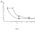
Figure 1 shows the schematic P - V diagram of the 'Air Standard Otto Cycle'; -
Figure 2 shows the schematic P - V diagram of the 'Air Standard Diesel Cycle' -
Figure 3 shows the schematic P V diagram of the 'Air Standard Atalla Mod. Cycle' with modification; -
Figure 4 shows the schematic P V diagram of the 'Air Standard Atalla Mod Cycle' for diesel engines with modification; -
Figure 5 shows the schematic T - S diagrams of the gasoline cycles (engines); -
Figure 6 shows the schematic T - S diagrams of the diesel type cycles; -
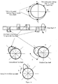
Figure 7 shows the schematic diagram showing components of the cylinder and rotation of the crank shaft (conventional and modified); -
Figure 8 shows the schematic diagram showing the required design modifications of the cam shaft and timing of opening of the inlet-outlet portal; -
Figure 9 shows the combustion chambers, conventional and modified cylinders; -
Figure 9a shows the combustion chambers, conventional and modified cylinders; -
Figure 10 shows the schematic diagram showing components of the cylinder and rotation of the crank shaft; -
Figure 11 shows a schematic diagram of the four-cylinder engine, and how cranks on the crank shaft are organized at 180 angular degrees from each other; and -
Figure 12 shows the schematic diagram showing components of the cylinder and rotation of the crank shaft (conventional and modied) of the two stroke engines. - Referring to
figures 7 ,8 ,9 ,9a ,10 ,11 and12 of the drawings, embodiments of the invention may comprise an engine which comprises apiston 1 housed within acylinder 3. However embodiments of the invention can be used to modify existing engines as well as converting conventional engines to operate according to embodiments of the invention, and so need not contain all the features of the engine. - The
piston 1 is housed within thecylinder 3 so that thepiston 1 is free to move within the cylinder. The piston is pivotally connected aliver 5 connection, which is in turn pivotally connected to a crankshaft (not shown). This connection of thepiston 1 to the crankshaft converts the reciprocating motion of the piston within the cylinder to rotary motion of the crankshaft. This connection also limits the movement of thepiston 1 within the cylinder between a position in which the piston head 8 (the face of the piston exposed to the combusted fuel or fuel and air) is furthest away from the crankshaft. This position is known as Top Dead Centre (TDC). The position of thepiston head 8 within the cylinder such that it is closest to the crankshaft is known as Bottom Dead Centre (BDC). In reciprocating combustion engines, TDC defines the volume of the combustion chamber, and BDC defines the volume of the combustion chamber plus the volume of the cylinder. The piston is free to travel from the Bottom Dead Centre Position (BDC) to the Top Dead Centre Position (TDC) within the cylinder. - The seal between the piston and cylinder must be sufficiently good so that expanding combusted gases (during the expansion stroke of the engine as the piston moves from TDC to BDC) cannot escape between the piston and cylinder joint. Furthermore, the seal between the piston and cylinder must be sufficiently good so that it can contain the air or air and fuel mixture as this is compressed by the piston in the cylinder during the compression stroke of the engine as the piston moves from BDC to TDC.
- The cylinder has a working volume which is equal to the volume traced out by the piston head as the piston head moves between BDC and TDC. Therefore the working volume of the cylinder will be the cross sectional area of the cylinder, for example the area of a circle if the cylinder has a circular cross section, multiplied by the distance between TDC and BDC. The volume of the cylinder is usually used as a measure of the power of the engine.
- One end of the
cylinder 3 is connected to acombustion chamber 7. The combustion chamber is the volume into which air or air and non-combusted fuel is compressed when the piston reaches the TDC position. The combustion chamber has at one end an inlet-outlet portal 9. Preferably the inlet-outlet portal comprises an inlet-outlet valve. The inlet-outlet portal has open and closed states and is connected to an air or air and non-combusted fuel source(s) via apipe 9 preferably a suction pipe. Typically, if the inlet-outlet portal is connected to an air and fuel source, there will be one source for the air and a different source for the fuel. The two components will then be mixed before being supplied to the suction pipe. Also provided at one end of the combustion chamber is anexhaust valve 11, shown infigure 7 in the open position, and aspark plug 13. Theexhaust valve 11 is connected to an exhaust pipe 15 so that combusted gas can be removed from thecombustion chamber 7. Usually,cams 17 mounted on acamshaft 19 will control the inlet-outlet portal 9 andexhaust valve 11. However, any other apparatus may be used to control the opening and closing of the inlet-outlet portal 9 andexhaust valve 11. - Embodiments of the invention modify the current design and operation of the reciprocating combustion engines, particularly, internal combustion engines (2 stroke or 4 stroke) of piston and cylinder type, operating on the principles of 'Air Standard Power Cycles' such as 'Air Standard Otto Cycle'
Fig 1 , or 'Air standard Diesel Cycle'Fig 2 . The said engines may use any of the fuels as the source of energy such as: natural gas, LPG, gasoline, kerosene, diesel fuel, light or heavy vacuum fuel, residue fuel, alcohol, bio fuel, hydrogen, combination of fuels or any other type of fuels. These are referred to as fuel. The modifications allow repeated operation of all the strokes of a full power cycle, for example four strokes (successions of: suction, compression, expansion and exhaustion strokes) in a manner which will result in the improved extraction of useful energy (thermal or mechanical) from the combusted fuels and thus improve efficiency and performance of these types of engines. In order to achieve this, embodiments of the invention modify conventional engines in two ways. - The piston and cylinder will usually be of circular section when viewed along the axis of movement of the piston. However, any shaped piston and cylinder could be used, for example oval or other shape.
- Embodiments of the invention change (modify) the existing cam shaft, by increasing (extending) the circular span of the mechanism of the cam shaft (metal humps) or any alternate devices with the function of the cam shaft, in positions that control the opening and closing of individual inlet-outlet ports (suction valves) of the involved engines. Note that only the cams actuating the inlet-outlet ports need to be modified, and the cams actuating exhaust ports remain unmodified. The cams will normally be mounted on a camshaft. The modified cam comprises a portion which is substantially oval in cross section. Preferably, the cross section of the cam is substantially that of a Cartesian oval. The modification should be such to extend opening of each inlet-outlet port for the duration of the movement of the corresponding piston as follows:
- a- Open Inlet-outlet port when the corresponding piston is at the Top Dead Center (TDC), (start of the 'Suction Stroke')
- b- Keep inlet-outlet port open, while the piston moves from TDC to Bottom Dead Center (BDC).
- c- Continue to keep the inlet-outlet port open while the piston had reached the BDC and turned to move back toward the TDC and covers a distance of, ideally but no necessarily, 30% to 60% of the distance between the BDC and TDC,
- This movement of the piston will evict a proportional volume of air-fuel or just air from the cylinder through the still opened inlet-outlet port back into the air-fuel supply pipe. When cams are used to actuate the inlet-outlet portal, this is achieved by extending the cam as shown in the modified cam in
figure 8 , so that it is offset from the BDC position of the piston. In this way, the inlet-outlet portal is controlled so that it is open for at least a portion of the first part of the compression stroke so that air or air and fuel mixture exits the combustion chamber and cylinder through the inlet-outlet portal. As shown infigure 8 , the modified cam is extended so that as it rotates clockwise, the extended hump of the cam shown as Z will force the inlet outlet portal to remain open as the piston moves from BDC to TDC, so that some air or air and fuel exits from the combustion chamber and cylinder. In this embodiment, the modified cam actuating the inlet-outlet portal opens the inlet outlet portal at point Y infigure 8 , at the normal time, which will usually when the piston head reaches TDC at the end of the exhaust stroke. - The evicted air-fuel mixture will not have undergone a noticeable change of composition, (probably with little higher CO2 content and higher temperature). This air-fuel mixture will mix with the other incoming fresh mixture being received from the carburetor or air supply pipe and air filter, and will be fed to the other cylinders of the said operating engine, which are or will be, performing the suction stroke (step),
- d- Close inlet-outlet portal when the said piston reaches the predetermined position as per point (c) above,
- The mechanical modification of the cam shaft (or any alternate device with the function of cam) should be able to force the closure of the inlet-outlet portal at the moment corresponding to position of the said piston at the end of covering the predetermined distance described above, which is preferably about 30% to 60% from BTC to TDC.
- Effect of the modified cam shaft mechanism (or alternate device) on operation of the 4 'strokes' of the involved engines, is as follows:
- Referring to
figure 7 from point A (TDC) to B (BDC) the inlet-outlet portal of any cylinder will be opened by means of the cam shaft mechanism at the moment when the said cylinder starts suction stroke with corresponding piston at the Top Dead Center (TDC). Then piston will move to the Bottom Dead Center (BDC) and fill the cylinder with air-fuel mixture, or just air in cases of injection type fuel supply, and in the case of pressure charging air-fuel mixture, opening of the inlet-outlet portal will allow feeding the cylinder with the air-fuel mixture. - Referring to
figure 7 , from point B (BDC) to point C, the said inlet-outlet portal will continue to be forced to stay open, while piston after reaching BDC of the cylinder (per item c above) will turn and move toward TDC and cover a predetermined distance, which could be, ideally but not necessarily, about 30% to 60% of the distance between TDC and BDC, and evict a proportional volume of air-fuel or just air from the said cylinder through the still opened inlet-outlet portal back into the air-fuel supply pipe. -
- ii-1 Eviction Step (section):
Fig 7 , from point B (BDC) to point C, Same as described in item c above. - ii-2 Compression Step (section):
Fig 7 , from point C to point A (TDC), - At the moment when the modified cam shaft, or any alternate device will force the closure of (closes) inlet-outlet portal of the said cylinder (as described in item c above), the piston will continue to move from point C toward the TDC and compress air-fuel mixture, or just air in the injection type engines. When the piston reaches TDC of the cylinder, the piston compresses the full volume of air-fuel mixture or just air from the cylinder into the combustion chamber and achieves the predetermined and required 'Compression Ratio' of the air-fuel mixture, or just air.
- Referring to
figure 8 , for a conventional camshaft, the time duration of operation of the suction valve is about 90 angular degrees, while the crank shaft will move 180 angular degrees. For the modified cam shaft, time duration of operation of the inlet-outlet port will be approximately 90 + 45 = 135 angular degrees, while crank shaft moves 270 angular degrees. - In this manner the inlet-outlet portal is expected to stay open for about 250 to 280 angular degrees of the full one revolution of the crank shaft, representing items a, b, c and d above.
- During the remainder of that revolution (80 to 110 angular degrees) inlet-outlet portal (and exhaust valve is in closed position) will be closed and piston will perform compression stage (section) of the compression stroke.
- Required economic 'Compression Ratio':
- a- For'Air standard Otto Cycle' -gasoline engines: 8 to 10
- b- For 'Air standard Diesel Cycle' -diesel engines 22 to 26
- The most suitable distance for the piston to travel and achieve the desired compression ratio, will be optimised by the actual operation experience to achieve the highest efficiency, which could be less than 30% or higher than 60%.
- In conventional engines, the expansion ratio is usually equal to the compression ratio, and is mostly:
- a- For 'Air standard Otto Cycle' -gasoline engines: 8 to 10
- b- For 'Air standard Diesel Cycle' -diesel engines 22 to 26
- Hence, by dividing the working volume (length) of the cylinders of the intended engines between the TDC and BDC into 2 sections, namely:
- 'Eviction Section', as per item i.1 above,
- 'Compression Section' as per item i-2 above,
- For 'Gasoline Engines', From 15 to 22
- For Diesel Engines, From 35 to 50
- While high pressure of the combustion gases will continue to force the involved pistons to travel the full stroke from TDC to BDC (working length of the said cylinder) under favourable positive pressure of those combustion gases,
- In reality the dividing line of the eviction and compression section of cylinders of the intended engines, could be selected to provide Expansion Ratio at over 100. However, the most practical dividing line of the eviction and compression section cylinders would be such, which will yield suitable and economic expansion ratio, highest efficiency and reliable and smooth operation of the said engine.
- As the cam shaft in the
gasoline 4 stroke engines makes one complete revolution for every 2 complete revolutions of the crank shaft, then the turning angular relation of these shafts, for the conventional and modified engines (cases) for a full Power Cycle (suction, compression, power stroke (expansion) and exhaustion) will be as follows in the table 1 below. - - Assuming the movement of piston for the eviction step from point B to Point C is equal to 50% of the stroke, (per item ii-2 above).
- In a further embodiment, the same effect of eviction of air-fuel mixture into the supply pipe can be achieved by closing the inlet-outlet portal before the corresponding piston reaches the BDC by 40 to 70%, which will lead to the said piston to move the remainder of the distance to BDC under partial vacuum.
- Such a case will also involve modifying the system in a different manner, particularly the cam shaft hump, which controls or actuates the opening and closing inlet-outlet ports, will be reduced rather than to be extended as mentioned above, as shown in
figure 8 (alternative). In this way, the inlet-outlet portal is controlled by offsetting the cam from the BDC position of the piston. The portal is closed before the piston reaches the BDC position during the intake stroke of air or air and fuel. Closing the portal for at least a portion of the last part of the intake stroke means that the volume of air etc taken into the combustion chamber and cylinder when the valve closes is less than the total volume of the combustion chamber and cylinder when the cylinder is at BDC. However the modified cam still opens the portal at the beginning of the intake stroke, shown as point Y infigure 8 . - Of course, the piston will continue to move towards the BDC position even when the valve is closed. When the piston reaches BDC, the cylinder will contain air or air and fuel, with a volume which is equal to that of the volume inside the combustion chamber when the piston is at the bottom dead centre position inside the cylinder, but the pressure of the gas contained within that volume will be at a lower, assuming that this is carried out at constant enthalpy (internal energy). Therefore, the inlet-outlet port is controlled to permit air or air and non-combusted fuel at a pressure P and temperature T to enter or enter and exit the combustion chamber and cylinder, and when closed to prevent air or air and non-combusted fuel from entering or exiting the chamber and cylinder. The volume of air or air and non-combusted fuel located inside the chamber and cylinder at the pressure P and temperature T when the inlet-outlet portal is closed (and remains closed), is less than the volume of the combustion chamber and cylinder when the piston is at the BDC position inside the cylinder.
Table 1 Description of Process (Stroke) Piston Movement Ref. ( Fig 7 )Angular Rotation of Shafts Degrees Conventional Engines Modified Engines Cam Shaft Crank Shaft Cam Shaft Crank Shaft 1- Suction Stroke a-Filling Step From Point A to Point B 90 180 90 180 b-Eviction Step From Point B to Point C - - 45 90 2- Compression Stroke a- Conventional Engines From point B to Point A 90 180 b- Modified Engines From Point C to Point A 45 90 3- Expansion Stroke a- Conventional Engines From Point A to Point B 90 180 b- Modified Engines From Point A to Point B 90 180 4- Exhaust Stroke From Point B to Point A 90 180 90 180 Total Degrees 360 One Full Rev. 2 x 360 2 Full Revs. 360 One Full Rev. 2 x 360 2 Full Revs. - Referring to
Figures 7 ,8 ,9 ,9a ,10 ,11 and12 of the drawings, the volume of the combustion chamber is reduced, to restore the compression ratio. In the conventional engines, the compression ratio is the ratio of the volume of the cylinder and combustion chamber when the piston is at the BDC position to the volume of the combustion chamber when the piston is at the TDC position. - As volume of the air-fuel mixture left in the cylinders at the end of the suction and eviction process per modification No. 1 above is reduced, then a proportionate reduction in the volume of the relating combustion chamber is required. This restores the predetermined and efficient compression ratio of the air-fuel mixture in the involved cylinder (engine). Referring to
figures 9 and9a , this is be achieved by means of, but not limited to, the following measures: - a- Add fixed dead volume, a substantially
incompressible member 21 to each
combustion chamber (cylinder C2 ofFig 9 andfig 9a ). The dead volume should be substantially incompressible and heat resistant at the pressures and temperatures experienced inside an internal combustion engine, for example at about 10 to 12 M Pascal and temperatures of up to 2500 K. The member should be fixedly attached to the inside of the chamber such that it does not impede the action of the piston in the cylinder. - b- Add fixed dead volume, a substantially
incompressible member 23 to the top face of
each piston (the piston head) (Cylinder C1), which could also change the position of TDC and BDC (to A1 and B1). This should be substantially incompressible and heat resistant at the pressures and temperatures experienced inside the internal combustion engine. The member should be fixedly attached to piston head such that it does not impede the action of the piston in the cylinder. - c- Change stroke of the involved pistons (cylinder C1) between points A1 and B2, so
that the stroke is extended beyond the normal BDC and TDC positions. When the piston is at the extended TDC position, the volume of the combustion chamber will be reduced compared to the unextended position of the piston at the TDC position. - d- Combination of the above and other options.
- The materials chosen should have a high Bulk Modulus (incompressibility) and resist high temperatures. Typically, most types of steel will be adequate and usually steel, with a bulk modulus of ~2×10¹¹ Pascal is sufficiently incompressible and resists higher temperatures. Any of these options provide the necessary conditions, which will allow to achieve the required and predetermined compression ratio for the air-fuel mixture, while the relevant piston will move a predetermined distance from the point (moment) of closure of the inlet-outlet portal (as described in the modification No. 1 above) to TDC, which could be about 30% to 60% of the distance between BDC and TDC, such as the distance from point C to TDC -
figs 7 and9 . - Compression ratio of the air-fuel mixture is a very important parameter in operation of 'Air Standard Cycles', and is usually selected based on the main objective to achieve the best efficiency (performance) from the fuel used in the intended engine under reasonably acceptable (controlled) operation conditions. The current levels of compression ratios are:
- a- For `Air standard Otto Cycle' -gasoline engines: 8 to 10
- b- For 'Air standard Diesel Cycle' -diesel engines 22 to 26
- The required volume reduction of the combustion chambers for any modified engine therefore, should be such that when any piston travels the remainder of the distance of the relating cylinder, from the position where the inlet-outlet portal of that cylinder was closed (as described above) to the TDC (travels about 40% to 70% of the full stroke), will achieve the predetermined compression ratio. The achieved compression ratio should be similar to the compression ratios of operation of the conventional engines (Air Standard Otto Cycles or Air Standard Diesel Cycles).
- Determination of the required reduction to a specific combustion chambers of an engine could be estimated as follows:
-
- Engine is 'Air Standard Otto Cycle', (4 cylinder and 4 stroke, gasoline type),
- Engine working size 2000 cc (cubic centimeter); Each cylinder has the working volume of 2000/4 = 500 cc (cubic centimeter),
- The original designed compression ratio was 9.5, for the full travel of the piston from BDC to TDC,
- Compression chamber size - volume (Vcomp) for the conventional cylinder, is :
- By closing the inlet-outlet ports at 50% distance of the relating pistons stroke from BDC to TDC for the modified engines, will mean that the said pistons have evicted about 50% of air-fuel mixture (or just air in cases of injection engines) from the corresponding cylinders back into the feeding pipe, and the cylinders are only half full of the air-fuel mixture. Hence, without the reduction of volumes of the combustion chambers, will mean that when the said pistons had reached the TDC of the relating cylinders, the achieved compression ratio will be only about half of what is required level, as follows:

- This is not a good and efficient compression ratio for operating 'Air Standard Otto Cycle' and will result in significant energy losses, particularly with the exhausted combustion gases. The physical reduction required of size of the combustion chamber to restore the compression ratio at 9.5 for an engine of 2000 cc size with 4 cylinders of 500 cc working volume each, will need to be reduced to:

- Hence, compression ratio (C R) of the modified engine (cylinder) will be restored to:

- This compression ratio of the modified cylinder will give a corresponding 'Expansion Ratio' in the same cylinder from TDC to BDC of the cylinder as follows:

- This is a significant increase in the expansion ratio and will provide suitable operation conditions to extract significant amount of additional energy (mechanical or thermal) from such a 'Power Cycle'.
- To achieve even a higher expansion ratio of the operating engines, it will be required to proportionally and physically reduce the size of combustion chamber, and reduce the volume of the compressed air-fuel mixture in the cylinder.
- Fore example, if it is required to have expansion ratio of 22, for the above cylinder, the required physical reductions in the volume of combustion chambers (Vc), will be estimated as:

Vc - is the required volume of combustion chamber
Vc = 23.8 cc - Required further reduction in size of the combustion chamber:

- Volume of the working air-fuel mixture to achieve compression ratio of 9.5 in this combustion chamber will be calculated from the following equation:

Vaf - is the working volume of air-fuel mixture in the cylinder,
Vaf = 202.3 cc
- Of the full cylinder size (volume), when operated on the conventional mode of operation (without modifications).
- By restoring the compression ratio of the gas-fuel mixture in gasoline engines - say to 9.5, for only half distance of piston movement between the BDC and TDC and half of the working cylinder volume of air-fuel mixture, will allow the combustion gases to achieve an extended expansion ratio of 18 to 19, and operate (move) the piston by positive pressure of the combustion gases for much longer distance (time) as compared with the current engines, as follows;
- i. Piston will perform the conventional part of the power cycle while travelling half of the cylinder distance between TDC and BDC. This section of the power cycle is performed under similar operation conditions and manner as the current conventional engines 'Air Standard Otto Cycle' in terms of:
- Achieve the expansion ratio of about 9.5,
- Combustion gases pressure decreases from over 7.5 M Pascal (75 Bar) down to about or little over 0.45 M Pascal (4.5 bar),
- Combustion gases temperature, decreases from over 2400 K down to about 1250 K (probably about 1400 K)
- ii. However, as the piston is approximately in the middle of the cylinder, it will continue to travel the other half of the cylinder to the BDC, and also under the continued action of high pressure of the combustion gases (very favourable conditions), which will expand further for another expansion ratio of about 8.5 to 9.5 (or even to 12). This will help to extract significant amount of additional useful mechanical energy from the combustion gases and improve the overall engine efficiency and performance.
- Pressure and temperature conditions of the combustion gases at the start and the end of this section of the expansion stroke are expected to be as follow:
- Pressure, Start: Over 0.45 M Pascal, End: Down to about 0.15 M Pascal,
- Start, Probably over 0.6 M Pascal
- Temperature, Start: Over 1250 K End: Down to about 950 K,
- Start, Probably over 1400 K
- Hence, the said engine will operate on only 50% to 60 % of the designed amount of the fuel, while it could be capable to achieve 85% to 95 % of the designed horse power of the same engine at the same RPM, (if it was working per the conventional power cycle). This entails that the engine will be capable to move the car for which it has been designed for much longer distance per litre of the used fuel (more kms). Embodiments of the invention improve the engine efficiency by more than 30% as compared with the current operation (assuming the reference efficiency of the current gasoline engines as 100 %, as will be shown in the example).
- Introduction of this
modification No 2, (Physical reduction of the Volume of the Combustion Chambers) into both the existing and future engines, could be achieved as follows: - The modifications are introduced into the existing vehicles by means of:
- a- Increase Piston Stroke,
Fig 9 Cylinder C1,
It is very difficult (and could prove very costly) to modify the stroke length of the existing and operating engine, for which the travel (stroke) of the corresponding piston is already designed , in a manner to be able to provide the required compression ratio 9.5. - b- Add appropriate dead volume to the top face of each piston, which could be possible by actually replacing the pistons
Fig 9 Cylinder C1.
This measure may also not be easy to introduce due to the current design restriction and negligible gap between the TDC and the engine cover (head). - c- Instead, reduce the size of the combustion chamber (over the piston when it reaches the TDC), by adding dead volume to the existing volume of each involved cylinder,
Fig 9 Cylinder C2.
It is believed that this measure should not be a very difficult or highly costly exercise, while the engine (car) performance is expected to significantly improve (as will be shown below). Position and shape of the dead volume, such as a piece of solid metal, could be fixed inside the combustion chamber in a selected suitable position. - d- Combination of any of these options as appropriate,
- e- Replace the existing engine cover (head) with a new one with reduced combustion chamber volume.
- The modification issues will be more simple and straight forward. They could be included with skilful engineering designs and measures.
- It is important to mention that most of the required modifications could be confined to the cover (head) part of the engine including the cam shaft modification. It is possible to just remove the engine head of the existing vehicle and perform the necessary modifications, or simply replace it with an already similar and modified engine head, and the modified car engine can be operated with significantly improved efficiency.
- For the fuel injection type engines, modification of injection mechanism will be required to adjust the fuel injection per the modified operation volume of the air in the combustion chambers.
- Embodiments of the invention modify current operating engines (such as gasoline or diesel engines) are not complicated, but rather simple and:
- Maintain the overall engine sizes at the existing levels,
- Maintain the bore and stroke of cylinders of the existing engines,
- Proportionally Reduce the size of the combustion chambers (dead volume), without affecting other components of the said engines,
- Reduce the volume of the working air-fuel mixture in the cylinder (ideally but not necessarily, by 30% to 60 %), while maintaining the compression ratio of the air- fuel mixture at the current levels,
- Utilize the full cylinder size for the expansion stroke (combustion gases expansion) and hence, significantly increase the expansion ratio of the combustion gases,
- Theoretically the expansion ratio could be made very high and as high as 100. However practically it should be optimized so that the involved engine will produce the highest mechanical and thermal efficiencies and performances and maintain the smooth operation of the engine, According to the available theoretical information, the most economic expansion ratios, are expected be:
- For gasoline engines 15 to 22
- For diesel engines and 35 to 50
- Extract significant additional useful energy (probably over 15%) from the released energy of the fuel (in the combustion gases), which could increase the Net extracted useful energy (mechanical efficiency) from the current levels:
- For gasoline engines, from the current 22 % to 28 %, to over 40 %,
- For diesel engines, from the current 36 % to 42 %, to over 50 %,
- To properly explain the novel idea and to show how the improvement in efficiency and performance of the involved 'Air Standard Cycles' is achieved, will require a detailed analysis and explanation of components and operation of a full 'Power Cycle' (for example for a 4 stroke gasoline engine) per the following steps:
- i. Describe and analyse operation of the 'Air Standard Otto Cycle' which is applied to the existing conventional gasoline engines (without modification),
- The min principles are also applicable to the "Air Standard Diesel Cycle'
- ii. Describe the modifications to the conventional engine in actual physical terms, and describe operation of the modified engine,
- iii. Analyse operation and performance of the modifications to the 'Air Standard Otto cycle'
- iv. Compare results of operation of both 'air standard power cycles',
- Referring to the
figures 1, 2 and5 to 12 , it should be stressed that description of the 4 stroke gasoline engines, carburetor type operating per the 'Air Standard Otto Cycle' is well known in the automotive industry, and the following description, is mainly for the purpose of the necessary comparison between operation of the conventional engines and operation of the same engine with the modifications. - Each function of the 4 (four) strokes of the conventional engine is usually completed during a full stroke of the piston (movement of the said piston from one end of the cylinder -say TDC to the other end BDC). These strokes are:
- Suction of fresh air-fuel mixture into the cylinder, as the piston moves from TDC to the BDC (or charged into, in the case of turbo and positive pressure charger),
- Compression of the air-fuel mixture (or just air in the injection type engines) is performed to induce favourable conditions into the power cycle, which will assist in extracting the highest amount of useful energy from the combusted fuel and achieve best efficiency. This stroke is performed while the piston moves from the BDC to TDC,
- This is the most important step of the 'Air Standard Power Cycle', which converts the thermal energy of combustion air-fuel mixture into the useful mechanical work. It is performed from a point when piston is ideally placed at the TDC and both inlet-outlet portal and exhaust valves are closed,
- This is a necessary step to evict the combustion gases from the cylinder to allow fresh air-fuel mixture to be brought in and perform the next cycle. This cycle is performed while piston is approaching the BDC, the inlet-outlet portal is closed and the exhaust vale will be opened in a position while the piston is approaching the BTC to allow for sufficient time to evict the combustion gases (which will significantly expand as the exhaust valve opens) with least amount of energy,
- Hence, piston by reaching the TDC at the end of the exhaust stroke, the full power cycle will be completed and another cycle will start immediately and in the same manner, as described in the steps a to d above. The cycles will repeat over and over during the operation of the said engine and could last sometimes for days or even years.
- Due to many factors of operation of the 'Air Standard Otto Cycle' and 'Air Standard Diesel Cycle', and particularly the very high temperature of the combustion gases at the start and during the 'Power Strokes', which could reach (instantaneously) over 2300 °C (2600 K), leads to significant losses of the released thermal energy from fuel combustion. Generally the released thermal energy of the fuel is divided into two major parts, which are:
- The useful energy (energy used for the purpose for which the engine is used, such as car movement, fluids pumping, etc.),
- The lost energy (not utilized for the purpose for which the engine is used),
- Ratio of the used useful energy Eu to the total released energy Et expresses the engine Net efficiency as follows:

Where: - η - is the engine thermal efficiency
- Eu - is the useful thermal energy, which could be used to perform the required work,
- Et - is the total thermal energy released from the fuel consumption
- Current level of efficiencies (η) of the conventional 'Air Standard Power Cycle', operating under favourable conditionals, are:
- 'Air Standard Otto Cycle' - in the range of 22 to 28 %
- 'Air Standard Diesel Cycle' - in the range of 36 to 42 %
- This means that a significant portion of the fuel energy (actually the majority portion) is lost during operation of the current conventional gasoline and diesel engines, and could not be used (for example) to move the intended vehicles, and is usually lost is the form of:
- a- Residual thermal energy in the exhaust combustion gases,
- b- Thermal energy lost to the cooling water or cooling air
- c- Mechanical losses, to operate engine's parts and components,
- Approximate breakdown (distribution) of the released energy between the outlets (components) in operation of the conventional engine, are usually as follows:

- The above table shows that the major part of the released energy is lost to the exhaust gases and to the cooling water. The medium size gasoline car engines (of 1600 cc to 2200 cc) seldom achieve above 10 to 14 km per litre, while the same size diesel cars can achieve about 15 to 17 km per litre. Even in ideal conditions the manufacturers may claim little higher performance.
- Hence, an amount of energy equal to moving the same car for about 35 to 40 km per liter is lost mainly to atmosphere (combustion gases and cooling water).
- To show, explain and substantiate the expected claimed improvements of engine efficiency and performance, the case will require to analyse the involved thermodynamics, operation and work principles of both the conventional 'Air Standard Otto cycle' and the modified 'Air standard Cycle', explain the modifications and compare the achieved results.
- Accordingly, the following description will include and show:
- i- Explanation of operation strokes and results under current conventional conditions,
- ii- Explanation of the same operation strokes and results with the modifications,
- iii- Comparison of the results,
- Refer to Figs. No 1, 2, 3, 4, 5 and 6
-
- Assume the compression ratio for operation of the current and future 'Air Standard Cycles' (gasoline engines) will be at 9.5 (which is a suitable and economic ratio). Comparison of each stroke of the involved engine is explained as follows:
- A-1 For conventional engines 'Air Standard Otto Cycle', from TDC to
BDC Fig No 7, and point A onFigs 1, 2 ,3 ,4 ,5 and 6 , - This stroke is performed to fill the cylinder with fresh air-fuel mixture and is considered mostly to require very little energy in operation and is treated as neutral stroke in terms of energy requirement or release.
- B-1 For the modified engines, from TDC to BDC and back to point
C Fig No 7, and point A onFigs 1, 2 ,3 ,4 ,5 and 6 , - For the modified engines the same principle of air-fuel mixture suction (intake) into the cylinder from TDC to BDC is applicable. There is no significant difference in energy requirements.
- However, when the said piston reaches BDC will turn and move back toward TDC, while inlet-outlet portal continues to be open. Hence, when piston moves toward TDC, will expel a proportional amount of air-fuel mixture from the cylinder back into the supply pipe, until the point when the inlet-outlet portal is closed, and by which time the piston will cover the predetermined distance of about 30% to 50% of the distance between BDC to TDC.
- Assume the piston is filled with 50% of the full working size (stroke).
- This operation also does not require much energy, and is neglected.
- The principle of compressing air-fuel mixture to the required compression ratio is applicable to both conventional engines and also to engines with the modifications.
- A-1 For conventional engines, piston moves from BDC to
TDC Fig No 7, which is from point A to point B onFigs No - The said piston moves and performs compression stroke, while both suction and exhaust valves are closed.
- B-1 For the modified engines, piston moves from point C to
TDC Fig No 7, which is from point A to point B onFigs1, 2 ,3 ,4 ,5 and 6 , - The modification divides the cylinder itself into two distinct sections of the piston action (movement) during the compression stroke, which are:
- i- Eviction Section: From BDC to point C (about 30% to 60% of the stroke -lower part of cylinder), while piston moves, it performs the eviction of a portion of air-fuel mixture from cylinder back into the air-fuel distributor (supply system) and inlet-outlet portal is still open during this section, and closes at the end of this section,
- ii- Compression Section: From point C (the position described, above) to TDC (upper part of cylinder), piston moves and performs the compression stroke; while both the inlet-outlet valve and exhaust valves are closed.
- Amount of air-fuel mixture in the said cylinder is about 50% of the full cylinder working size (stroke)
- For operation of the conventional engines, compression of the air fuel mixture takes place by the movement of the relevant piston from BDC and when the piston reaches TDC, will complete the compression stroke and pushes the entire amount of the air-fuel mixture, or jut air, into the combustion chamber. This process requires significant amount of energy and causes the adiabatic rise of both temperature and pressure. Theoretical pressure increase will be according to the following equation:

Where: - P1 - Is the air-fuel mixture pressure at the end of the suction stroke and the start of the compression stroke, and is ideally (usually) 0.1 M Pas (1 bar),
- P2 - Is the air-fuel mixture pressure at the end of the compression stroke and the start of the power stroke (prior to ignition of the fuel),
- V1 - Is the air-fuel mixture volume at the end of the suction stroke and the start of the compression stroke (full volume of the cylinder and the combustion chamber),
- V2 - Is the air-fuel mixture volume at the end of the compression stroke and the start of the power stroke (volume of the combustion chamber),
- K - Is a constant and expresses Cp / Cv, and for air: K = 1.4
- Cp - Is specific heat of air under constant pressure,
- Cv - Is specific heat of air under constant volume,
- Temperature of the compressed air-fuel mixture will also increase adiabatically, and will be increasing according to the following equation:

Where: - T1 - Is the air-fuel mixture (atmospheric air) temperature at the end of the suction stroke and the start of the compression stroke,
- T2 - Is the compressed air-fuel mixture temperature at the end of the compression stroke and the start of the power stroke (and prior to the ignition of the air-fuel mixture),
- Assume the suction temperature (atmospheric Temperature) is 15 °C (288 K), then the theoretical temperature at the end of the compression stroke will be:

T2 = 710 K - As could be noticed, this stroke requires significant amount of mechanical energy to increase the pressure and temperature of the compressed air-fuel mixture. The required power is usually provided by the Power Stroke of another cylinder (or fly wheel), but will then be released as part of released power during the subsequent Power Cycle of the said cylinder, which results in a balanced situation, except for some losses.
- Compression stroke (process) will be performed for engines with the modifications, in the same manner as described for the 'Air Standard Otto Cycle' with the associated corresponding energy requirement and pressure and temperature increases.
- The major difference is in the actual volume of air-fuel mixture in cylinders of exactly the same stroke and bore (same size). As mentioned for the suction stroke (inlet-outlet stroke), the cylinder will be only about 50% full with air-fuel mixture of the full working stroke -plus the combustion chamber.
- Hence, if the volume of air-fuel mixture in the conventional cylinder will be twice that of the air-fuel mixture for the modified cylinder and are compressed to the same compression ratio, then obviously the required energy for performing the compression ratio will also be twice for the conventional engine. However, there will be little difference in the net energy requirement, as most of the spent energy for compression is recovered during the subsequent expansion (power) stroke.
- As for the pressure and temperature at the end of compression section, they will be similar to the pressure and temperature of the conventional 'Air standard Otto Cycle' as follows (if same compression ratio is applied):
- Pressure 2.33 M Pascal (23.3 Bar)
- Temperature 710 K
-
- For conventional engines, from point B to Point C and ends in point D on Figs. No 1, 2, 3, 4, 5 and 6,
- For the modified engines, also from point B to Point C to point D and ends in point E on
Figs. 3 ,4 and6 , - During this stroke, two simultaneous processes will take place, for both the conventional and the modified engines, they are:
-
- From point B to point C for 'Air Standard Otto Cycle',
Fig. 1 , - From point B to point C for 'Air Standard diesel Cycle'
Fig. 2 - However, the major differences between 'Air Standard Otto Cycle' and 'Air Standard Diesel Cycle' are:
- a- Very high combustion pressure of 'Air Standard Diesel Cycle', due to the much higher compression ratio,
- b- Auto Ignition of the air-fuel mixture in 'Air Standard Diesel Cycle', while the 'Air Standard Otto Cycle' has the electrical ignition system, c- In the fuel introduction (injection) type Diesel Engines, fuel injection could be controlled in a manner to sustain near a constant and predetermined pressure (close to the compression pressure) while the piston moves for about 20 to 30 % of the distance from TDC to BDC.
- d- This process assists to extract more useful energy from combustion gases and increase the cycle's efficiency.
- Amount of fuel used (supplied to the engine) for the normal operation of `Internal Combustion Engines' (for speeds of 70 to 100 km/h) is such to produce about 2300 to 3260 Joule (550 to 780 cal) per litre of air, to achieve air to fuel ratio of about 16.5 to 19).
- For analysis of this 'Power Cycle', it is assumed:
- a-1 Ignition of the air-fuel Mixture will be initiated by the action of the cam shaft and the spark plug,
- a-2 Ignition (combustion) of the air-fuel mixture and release of energy is instantaneous process,
- a-3 The above process takes place at constant volume (within the combustion chamber volume),
- a-4 The specific heat of the combustion gases at 1.15 Joule (0.275 cal) per gram per one degree °K at temperature of 750 K plus,
- a-5 Density of air-fuel mixture (gases) at 1.14 g / Litre,
- a-6 The calorific value of the supplied fuel at 46,872 Joule (11200 cal) per gram,
- a-7 Supplied energy is 2720 Joule (650 cal) per litre of air at normal conditions,
- This energy supply to the intended engine is normally related to the weight ratio of air to hydrocarbon fuel mixture at:

- This rate is relatively high as compared with the ideal ratio of air to fuel of: (16.0 to 16.5) / 1 ; which provides:
- Better economic combustion conditions of the fuel consumption.
- Excess oxygen in the exhaust gases at about 2 to 4 % and
- Better conditions of fuel combustion.
- Furthermore, the high air to fuel rate (19.64 /1) will cause significant energy losses as it means heating additional amounts of air -more than 15 to 20 % above the ideal rate, from 288 K to over 1200 K and exhausting to atmosphere.
- The supplied thermal energy, assumed at 2720 Joule (650 cal) per litre, will raise temperature of the compressed (and combusted) gases in the combustion chamber instantaneously and very sharply. Theoretical increase of temperature from combustion of fuel in the combustion chamber (Ticrease), assuming an instantaneous release of energy, will be:

Where : 1.150 is the specific heat of air joule/g.K.
1.14 is the air density at 298 K - Overall combustion gases temperature (theoretical) at the end of the full combustion of fuel Tth com, assuming ideal conditions, will be :

Note : Theoretical ideal temperature (Tth id) under conditions of ideal air to fuel ratio of 16, will be significantly higher and over 3200 K: - Temperature increase of the combustion gases in the combustion chamber will result in the pressure increase, per the ideal gas equation, under constant volume V :

Where: - P3 - is the pressure of the combustion gases after ignition of the air-fuel mixture and transfer of the full theoretical released heat to those gases,
- T3 - is the temperature of the combustion gases after ignition of the air-fuel mixture and transfer of the full theoretical released heat to those gases,
- Hence, the theoretical pressure and temperature after fuel ignition and start of the 'Power Stroke' of the conventional 'Air standard Otto Cycle' will be:
- i. Pressure 9.13 M Pascal
- ii. Temperature 2785 K
- However, from the practical experience of operation of 'Internal Combustion Engines', both the combustion gas temperature and pressure are significantly lower than these levels, because of:
- i- Exact timing (tuning) of the ignition moment, (preferably little before the piston reaches the TDC) is difficult to maintain effectively,
- ii- Time required to complete the fuel combustion, (preferably very fast and while the piston has just passed the TDC and starts to move to the BDC),
- iii- Heat transfer from the very hot gases (temperature over 2400 K) to cylinder's walls (metal) and the cooling water or air,
- This is an unavoidable factor, and all the attempts are to minimize the heat loss while maintaining the efficient and smooth operation of the engine (power cycle) rather than to eliminate it Etc.
- Actual highest temperature and pressure of operation of the gasoline engines could be lower by as much as 15 to 25 % than the theoretical highest values (per the 'Air Standard Otto Cycle'),
- Air-fuel ignition (or auto-ignition in the case of diesel engines), energy release and pressure increase described before, for the 'Air Standard Otto Cycle' will also be performed in the same manner for engines with the modifications.
- Again the major difference is in the actual volume of air-fuel mixture in cylinders of exactly the same stroke and bore (same size). As mentioned before the said cylinder will be only about 50% full with air-fuel mixture of the full stroke - plus the combustion chamber.
- As for the pressure and temperature after fuel ignition and start of the 'Power Stroke' will be similar to the pressure and temperature of the conventional 'Air standard Otto Cycle'
- Pressure 9.13 M Pascal
- Temperature 2783 K
-
- For conventional engine, from point C to point D, on Figs, No 1, 2, 3, 4, 5 and 6
- For the modified engine, from point C to point D, and to point E on Figs, No 3, 4, 5 and 6,
- Expansion of combustion gases for both the conventional and modified engines starts immediately after the piston had passed the TDC and moves toward the BDC. Expansion of the combustion gases will also take place adiabatically and will be per
Equations 2 and 3 (mentioned before). - Assume the actual temperature at the start of the expansion stroke is 2400 K
- Assume the actual pressure at the start of the expansion stroke is 7.5 M Pascal (75 Bar),
- From point C to point D on Figs. No 1, 2, 3, 4, 5 and 6,
- Temperature at the end of the expansion stroke (BDC) will be:
- A-1 Theoretical temperature (Tth) at the end of the expansion stroke (BDC), will be:

- A-2 However, expected temperature (Te) at the end of the expansion stroke (BDC) with the assumed temperature at the start of expansion stroke (TDC) at 2400 K, will be:

In reality, the actual temperature at the end of the expansion stroke and the start of exhaust stroke, is significantly higher (by as much as 15 to 30%) than both of these temperatures, due to the fact that combustion of the air-fuel mixture could still be in progress, while the piston is close to the BDC.
Assume: Exhaust temperature of the combustion gases is about 1250 °K.
Exhausted Energy (Eex) with combustion gases will be:
Note : Specific heat of the combusted gases is expected to be little higher at higher temperatures,
Per cent exhausted energy = (1106/(2720/1.14))x 100 = 46.35%
This is a very substantial amount of energy, which is lost with exhaust gases. - A-3 Theoretical pressure at the end of the expansion stroke at the point E, (PE) with conventional engine, will be:

- A-4 Pressure at the end of the expansion stroke at point E, (PE) with the assumed pressure of 7.5 M Pascal (75 Bar) at the start of the expansion stroke (conventional engine), will be per eq. 2:

- A-1 Theoretical temperature (Tth) at the end of the expansion stroke (BDC), will be:
- However, the actual pressure at the end of the expansion stroke PD, will be significantly higher due to the very high temperature of the combustion gases at the end of the expansion stroke, and will be:

- This is again a very high pressure and could perform proportionate mechanical work, if it could be beneficially utilized, particularly as it is applied to the full volume of the cylinder of combustion gases.
- The modification of the engine, addresses this exact issue and try to utilize most of this available (but currently lost) mechanical work (energy), prior to expelling the combustion gases to atmosphere, as explained below.
- Points C to D then to E on
Figs No - Combustion gases continue to expand adiabatically, under controlled conditions by another 9.5 times of the size of the combustion chamber (from point D to point E on the
Figs 3 and4 ) starting from the end point of the conventional cycle expansion section. This will assist to complete combustion process of the introduced fuel and significantly reduce the exhaust temperature, as shown below: - B-1 Theoretical temperature at the end of the expansion stroke Tthmod, will be:

- B-2 Expected temperature (TExmod) at the end of the expansion stroke with the assumed initial temperature at 2400 K, will be:

However, the real exhaust temperature will be slightly higher, due to the much longer time of combustion, and could be (conservatively) at about 850 to 1000 K.
This is a very significant reduction of the exhaust temperature of the expelled gases and the associated thermal energy. Exhausted energy with combustion gases with the modifications will be (assuming the exhaust temperature at high 950 K):


By all measures and considerations, this is a very significant reduction in the expected exhausted thermal energy, and could be utilized usefully to move the intended vehicles. - B-3 Theoretical pressure at the end of the modified expansion (adiabatic) stroke Pth,mod , will be:

Pmod = 0.146 M Pascal (1.46 Bar) - B-4 Expected pressure at the end of the modified expansion (adiabatic) stroke Pmod with the assumed initial temperature at the start of expansion stroke of 2400 K, will be :

Pmod = 0.119 M Pascal (1.19 Bar) - However, the actual pressure at the end of the expansion stroke P will be slightly higher than both of these pressures, depending on the exhaust temperature, and conservatively could be at about 0.14 to 0.17 M Pascal (1.4 to 1.7 Bar), due to higher exhaust temperature.
- On
Figs. 3 and4 the area from point D to Point E to point F to point A and back to point D represents the additional useful energy, which will be added to the conventional engine useful energy between the point A to point B, to point C, to point D and back to point A. This area could represent a major input and will significantly improve the operation efficiency and parameters of the vehicles. - Note: For injection cars, the injection of fuel will need to be tuned also with the modification of the actual amount of air to fill 30% to 60% of the cylinder size:
- Summary of the temperature and pressure for the two 'Power Cycles' at the end of expansion stroke are:
Otto Cycle Modified Power Cycle i- Temperature K • Theoretical 1132 856 • With assumed temperature at the Start of expansion stroke 975 739 • Assumed operational 1250 950 ii- Pressure M Pascal • Theoretical 0.391 0.146 • With assumed pressure at the start of expansion stroke 0.321 0.119 • Assumed operational 0.43 0.15 lii- Rejected heat with combustion gases Joule • With assumed exhaustion temperature 1106 761 - The above data show a significant improvement (reduction) in the temperature and pressure of the combustion gases at the end of expansion stroke and start of the exhaust stroke.
- This stroke is performed to evict the combustion gases from the cylinder to the outside environment and prepare that cylinder for the next cycle. This stroke does not require high energy demand at lower engine speeds (crank shaft) of less than 1600 revolution per minute (RPM), and also depends on the size of the exhaust valve. However as the engine speed increases with increased energy input into the engine and the resulting significant increase of residual pressure and temperature of the combustion gases at the end of the power stroke (combustion gases expansion), energy requirement to evict the combustion gases out of the cylinder increases. It is expected that by the time the engine speed reaches to about 3000 RPM, eviction process of the combustion gases may require up to 0.1 M Pascal (over 1.0 bar) pressure from the piston and crank shaft.
- - Due to the significant reduction in the volume of fresh air-fuel mixture in the cylinders and the resulting significant reduction in the residual pressure and temperature at the end of the power stroke (combustion gases expansion) of the modified engines, demand for energy to evict the combustion gases will be negligible at engine speeds (crank shaft) of even over 6000 RPM.
► Overall summary of operation results (data) of the two power cycles is shown in the
table 2 below.Table 2: Summary of results of the operation of the two types of engines. Description Gasoline engine, 4 stroke Units Conventional Engine Modified Engine 1- Compression Ratio 9.5 19 2- Temperature at the end of compression stroke K 710 710 3- Pressure at the end of compression stroke M Pascal 2.33 2.33 4- Energy introduced joule/litre of air Joule 2720 2720 5- Temperature at the end of fuel combustion (Assumed) K Theoretical 2783 2783 Assumed 2400 2400 6- Temperature at the end of Expansion stroke Theoretical K 1132 856 With Assumed initial temperature K 975 739 Assumed K 1250 950 7- Pressure at the end of Expansion stroke M Pascal Theoretical 0.391 0.138 with the assumed initial expansion temperature of 2400 K 0.321 0.119 With Assumed exhaust temperature 0.43 0.15 8- Energy exhausted with combustion gases Joule /litre 1106 761 9- Thermal efficiency % 53.64 68.1 - The table shows significant increase of thermal efficiency of the modified engine to 68.1 % as compared with efficiency of the conventional engine of 53.64 %, with the increase of about 14 %. Reduced temperature of the engine operation by more than 200 K will in turn reduce the energy lost with cooling water by several percents (probably by more than 5%) and will result in an overall improvement of the gasoline engines operation efficiency by over 19% (of the net energy input) as compared with current operation of the 'Air Standard Otto Cycle'. A near similar improvement in the efficiency in operation of 'Air Standard diesel Cycle' could also be expected.
- (This could be tested and further improved in actual experience).
- Below is the comparison of distribution of the released energy between the major outlets (components) in operation of the conventional engines and the expected distribution from operation of the modification, is as follows in table 3.
Table 3 comparison of distribution of the released energy. Energy outlet Gasoline Engines Diesel Engines Conventional Operation % With Modification % Conventional Operation % With Modifications % 1- Useful energy to move the car 22 to 28 40 to 48 34 to 40 45 to 55 2- With exhausted combustion gases 44 to 48 26 to 32 36 to 40 21 to 28 3- With cooling water 23 to 25 20 to 25 18 to 21 18 to 21 4- Mechanical Losses 5 5 6 6 Total 100 100 100 100 - Note: These figures are only estimates and may be different in the actual practice. The changes are expected to be positive.
- The modifications significantly increase efficiency and performance of the involved engine (even much higher than those shown in the above tables) and subsequently increase the km per litre for the automotive industry. The modifications are very useful in the operation of larger engines, such as the Diesel Power stations, which operate on light and heavy Vacuum Gasoil (ship engines) with cylinder bore and stroke of over 300 mm. The reduced temperature of the exhaustion gases and extended expansion stroke are expected to noticeably improve the engine's efficiency and performance, in terms of:
- Significant reduction in the exhaust gases temperature (probably by more than 300 K, from -say 1250 K to below 950 K)
- less heat loss to the cooling water or cooling air due to the overall significantly reduced operation temperature, while maintaining and improving the main operation parameters as compared with the conventional engine,
- Only air cooling may prove to be sufficient even for engines of 2000 cc size, - less mechanical losses by restricting the very high pressure and temperature to the top quarter portion of the stroke (softer operation conditions),
- less requirement for cooling water or cooling air, by converting more thermal energy into the useful mechanical work,
- Less severe conditions in the exhaust pipe, due to the reduced amount of combustion gases (probably by more than 40%) and lower temperature as mentioned in
item No 1 above, for the same gross horse power, - For smoother operation of the involved engines, cranks arrangement on the crank shaft for the future 4 cylinder engine, may be arranged at 90 angular degrees from each other, as compared with the current preferred arrangement of 180 angular degrees (
fig 11 ), -
- Very significant reduction in the emission of CO2 and other pollutants to atmosphere by the increased efficiencies of the Internal Combustion Engines, which should require much less fuel for the same net break horse power,
- Emission of significantly less harmful and incompletely combusted mater (quantity and quality) to atmosphere by allowing much more time for completing the combustion of fuels in the cylinder itself and under conditions of higher temperature,
- Hence more favourable and significantly improved environmental conditions from the operation of such engines,
- The modifications (when introduced into the existing cars) may slightly change engine's power, particularly in achieving very high speeds, of say over 120 km/h. However, this may be a small price to afford as compared with significant expected savings in the purchase of fuels (LPG, gasoline, diesel, etc). It may also require a little larger 'fly wheel' to ensure a continuous engine operation at low parking RPMs of -say about 750 RPM.
- The issue of sufficient performance (higher power and speed requirements) for the new engine, could be included directly in the designs, and should not pose a problem for expert designers.
- To show the impact of a lower case of compression ratio, the same above analysis will be performed for a case when the cylinder is filled 60% at the start of compression stroke.
- With 60% of the cylinder full of air-fuel mixture at the start of the compression stroke, the new compression ratio will be:

- Temperature and pressure at the end of the compression stroke will be:

- The real exhaust temperature could be (conservatively) about 920 to 1000 °C,
- This is a very significant reduction of the exhaust temperature of the expelled gases and the associated thermal energy. Exhausted energy with combustion gases with the modifications will be :

- Per cent of the exhausted energy will be:


- By all measures and considerations, this is also a very significant reduction, and could be utilized usefully to move the intended vehicles.
- Theoretical pressure at the end of the modified expansion (adiabatic) stroke Pmod, will be :

- This pressure is also significantly lower than the experienced pressures with conventional operation of the 'Air standard Otto Cycle' (gasoline engines).
- As could be seen, from
Figs 3 and4 , further energy extraction (mechanical) from the combustion gases (beyond 20 compression ratios) within the cylinders may prove negligible or highly costly, as the pressure of the exhaust gases could actually be reduced to less than 0.12 M Pascal abs (1.2 bar) abs with compression ratios of about 19 to 22. - Actual experience may prove that this residual positive pressure will be required, which is just enough to avoid creating a vacuum inside the cylinder under low RPM (parking conditions).
- These analysis show, that a significant amount of additional energy could be extracted from the combustion gases and used to perform the useful mechanical work (to move the car) as shown in the extended expansion stroke on the PV diagrams
Figs 3 and4 . - The 'Power Cycle' shown in the
Figs 3 and4 , is a new type of 'Air Standard Power Cycles', which can significantly extend the expansion stroke of this Power Cycle beyond those of both the conventional 'Air Standard Otto Cycle' and 'Air Standard Diesel Cycle' and is substantially different from both of them. - This new power cycle re-organizes and re-designs the engines operation as follows:
- i- Splits the conventional suction stroke to:
- a- Filling stage,
The moving piston from TDC to BDC will fill the cylinders with air-fuel mixture, (inlet-outlet portal is open) - b- Eviction stage,
When the said piston reaches BDC and fills the said cylinder with air-fuel mixture as per stage a- above, the piston will turn and starts to move toward the TDC and covers a predetermined distance of about 30% to 60% of the distance between BDC and TDC, with inlet-outlet portal still open during this section. During this stage, piston will evict a proportional portion of air-fuel mixture back into the fuel distribution (supply) pipe.
Inlet-outlet portal will be closed at the piston position corresponding to the end of the predetermined distance of 30% to 60% of the full distance between BDC to TDC.
- a- Filling stage,
- ii-Splits the conventional compression stroke to:
- a- Eviction stage, while piston moves from BDC and covers a predetermined distance
between BDC and TDC as per item i-b above, - b- Compression stage, while piston moves from the predetermined distance (as
described in point a above) and moves to the TDC of the corresponding cylinder, (covers the top half -part of that cylinder),
- a- Eviction stage, while piston moves from BDC and covers a predetermined distance
- lii- Extend the expansion stroke:
- a. Significantly Extends the expansion stroke of the Power Cycle and accordingly the expansion ratio of the combustions gases, beyond those of both the conventional 'Air Standard Otto Cycle' and 'Air Standard Diesel Cycle'.
- It actually provides the opportunity to select the expansion ratio for the intended engines in a manner to achieve the highest efficiency for that engine.
- a. Significantly Extends the expansion stroke of the Power Cycle and accordingly the expansion ratio of the combustions gases, beyond those of both the conventional 'Air Standard Otto Cycle' and 'Air Standard Diesel Cycle'.
- vi- Improve conditions of exhaustion stroke:
- a- Exhaust stroke is similar to the conventional operation of the involved engines and
is performed while corresponding piston moves from BDC to TDC. However the main difference in the actual size of the exhausted combustion gases, which is much smaller in the modified engines and at lower pressure and temperature. Hence, requirement for power to evict the combustion gases out of the cylinders will be much less (negligible)
- a- Exhaust stroke is similar to the conventional operation of the involved engines and
- As could be noticed the new power cycle is substantially different from both of the conventional 'Air Standard Otto Cycle' and 'Air Standard Diesel Cycle'. It has it's own analytical characteristics and approach and of particular importance is the provision of high flexibility of the expansion ratio of the combustion gases. Controlling system and mechanism (cam shaft) could also be further tuned and controlled to have lower expansion ratios with lower RPM of the 'crank shaft' and higher expansion ratios with higher RPM, and also to control the exhaust pressure just above atmospheric pressure.
- It is applied to operation of the reciprocating 'internal combustion engines', which have some or all the modifications introduced into their construction, and will provide operation conditions of higher efficiency and performance for the said engines.
Figs 3 ,4 ,5 and 6 , - It is only fair that this new applied "Power Cycle " to be named as the: " Air Standard Atalla Modified Cycle ".
- Engines operating on this 'Air Standard Atalla Modified Cycle' could be categorized and expressed in the actual practice as:
- Atalla Mod 30 - The Cylinders will be filled with 70% of the full size, - Atalla Mod 40 - The Cylinders will be filled with 60% of the full size, - Atalla Mod 50 - The Cylinders will be filled with 50% of the full size, - Atalla Mod 60 - The Cylinders will be filled with 40% of the full size, - And all other selected filling of the cylinders, as:
- Atalla Mod 35, Atalla Mod 38, or Atalla Mod 42, or Atalla Mod 45, etc.
- These are usually small type of engines and applied to motorcycles (fast moving vehicles). However, the modification could also be successfully applied to the two stroke engines and improve their efficiency, performance and the environmental issues associated with these types of engines.
- The modification for 'Air Standard Otto Cycle' or the 'Air Standard Diesel Cycle', could also be applied to the two stroke engines. The modifications comprise also the mechanism on the cam shaft or any alternate devices with the function of the cam shaft, which controls the opening and closing of inlet-outlet portal, and the required reduction of size of the combustion chambers.
- However, due to the different mode of operation of the two stroke engines, which could be characterized by:
Fig. 12 , - a- All four operation strokes are performed during one full revolution of the crank shaft,
- b. There is no exhaust valve,
- c. Exhaustion of combustion gases takes place through a longitudinal slot in the lower section of each cylinder,
- d. Air-fuel mixture is little compressed and fed to the cylinder under positive pressure,
- e. The fed air-fuel mixture into the cylinder also performs the eviction of the combustion gases (exhaust process - stroke),
- f. Efficiency of these engines is usually very low,
- Hence, the modification will need to be applied skilfully and carefully to realize the expected improvements. Modification of the mechanism controlling opening and closing of the inlet-outlet portal should be applied (introduced) in a manner to allow the full power cycle (2 strokes - for every one full revolution of the crank shaft) to run smoothly and trouble free also, as compared with the conventional operation, and improve the efficiency of the involved engines.
- The increased efficiency of the two-stroke engine could be explained from the operation strokes of the modified engine as compared with the conventional engine, as follows:
- For every full revolution of the Crank Shaft (360 angular degrees), starting from point A (
fig. 12 ) the two strokes of the modified engine, as compared with the conventional engines, will be performed as follows:- Assume the power cycle start from Power Stroke :
-
- Piston will move from TDC to point C (
Fig 12 a ) and from point A to point C (fig 12 b ) - Ignition of the compressed air-fuel mixture commences and significantly raises temperature and pressure of the combustion gases, which will expand and push the piston down from TDC to point C (
Fig 12 a ), or point A to point C on the angular path of the crank shaft (fig 12b ), - Expansion ratio: 8 to 9
-
- Piston will also move from TDC to point C (
Fig 12 a ) and from point A to point C (fig 12c ) - Ignition of the compressed air-fuel mixture commences the fuel combustion and significantly raises temperature and pressure of the combustion gases, which will expand and push the piston down from TDC to point C (
Fig 12 a ), or point A to point C on the angular path of the crank shaft (fig 12 c ), - Expansion ratio: 16 to 18
-
- Piston will move from point C to BDC and return back to point C (
Fig 12 a ) and from point C to point D1 (fig 12 b ), - When piston reaches and exceeds Point C, it will also exceed the top line (edge) of the exhaust slot and the combustion gases still under high pressure and at very high temperature will start to exit (at very high speed) the respective cylinder into the exhaust pipe and then to outside atmosphere. The process will continue while the piston moves and reaches BDC (point D on
fig 12 a ) and returns to move back towards TDC and reaches point D1 (fig 12 a ) at which point the piston will pass the top edge of the exhaust slot and complete the exhaust process (stroke). -
- Piston will also move from point C to BDC and return back to point C (
Fig 12a ) and from point C to point D1 (fig 12 c ), - When piston reaches and exceeds Point C, it will also exceed the top line (edge) of the exhaust slot and the combustion gases still under high pressure and at very high temperature will start to exit (at high speed) the respective cylinder into the exhaust pipe and then to outside atmosphere. However, the exit pressure and temperature of the combustion gases are significantly lower that those of the similar conventional two-stroke engine. The process will continue while the piston moves and reaches BDC (point D on
fig 12 a ) and returns to move back towards TDC and reaches point D1 (fig 12 a ) at which point the said piston will pass the top edge of the exhaust slot and complete the exhaust process (stroke). -
- Piston will moves from point C to BDC and return back to point C (
Fig 12 a ) and from point C to point D1 (fig 12 b ), - When piston reaches BDC, point D (
fig 12 b ), charge valve (suction) opens, - Air-Fuel mixture will be charged under positive pressure into the cylinder, and pushes the combustion gases through the exhaust slot into the exhaust pipe and outside. This process will continue until piston reaches point C (
Fig 12a ) point D1 (Fig 12 b ). Although the replacement of the combustion gases will not be complete, but it is expected that most of the combustion gases will be pushed out of the cylinder. - When piston reaches point C (
Fig 12 a ), Charge valve will be closed, - Cylinder will be filled to point C (
Fig 12 a ) with fresh air-fuel mixture. -
- Piston will also move from point C to BDC and return back to point C (
Fig 12a ) and from point C to point D1 (fig 12 c ), - When piston reaches BDC, point D (
figs 12 a and 12c), charge valve (suction) opens, - Air-Fuel mixture will be charged under positive pressure into the cylinder, and pushes the combustion gases through the exhaust slot into the exhaust pipe and outside. This process will continue also until piston reaches point C (
Fig 12a ) point D1 (Fig 12c ). Although the replacement of the combustion gases will not be complete, but it is expected that most of the combustion gases will be pushed out. - When piston reaches point C (
Fig 12 a ), Charge valve (inlet-outlet valve) will continue to be open and will be closed when piston reaches point E (Fig 12 c ),
This will allow the said piston to evict some air-fuel mixture from the involved cylinder, from point C to point C1 (Fig 12 a ), (from point D1 to point E,Fig 12c ), - Cylinder will be filled from TDC to point C1 (
Fig 12 a ) with fresh air-fuel mixture (40% to 60% of working size of the conventional cylinders). -
- Piston will moves from point C to TDP (
Fig 12 a ) and from point D1 to TDC point A (fig 12b ), -
- Piston will moves from point C1 to TDP (
Fig 12 a ) and from point D1 to point A (TDC) (fig 12 c ), - By introducing the modifications, operation of the same revolution will change slightly, but expected to significantly improve the engine's efficiency and performance. Hence, for every full revolution of the Crank Shaft (360 angular degrees), starting from point A (
fig. 12b ) the two strokes of the modified engine, as compared with two strokes of the conventional engine, as shown in table 4. - Embodiments of the invention significantly improve operation of the two stroke engines, and in a similar manner as the modified 4 stroke engines, in terms of:
- Significant reduction in the exhaust gases temperature (probably by more than 400 K, from -say 1400 K to below 1000 K)
- less heat loss to the cooling air due to the overall significantly reduced operation temperature, while maintaining and improving the main operation parameters as compared with the conventional engine,
- less mechanical losses by restricting the very high pressure and temperature to the top quarter portion of the stroke (softer operation conditions),
- Less severe conditions in the exhaust pipe, due to the reduced amount of combustion gases (probably by more than 40%) and lower temperature as mentioned in
item No 1 above, for the same gross horse power, - Very significant reduction in the emission of CO2 to atmosphere by the increased
efficiencies of the Internal Combustion Engines, which should require much less fuel for the same net break horse power,
Emission of significantly less harmful and incompletely combusted mater (quantity and
quality) to atmosphere by allowing much more time for completing the combustion of fuels in the cylinder itself and under conditions of higher temperature,
Significant reduction of the engine noise, as a result of the much reduced exhaust
pressure,Table 4 (continued): Operation of conventional and modified two-stroke engines according to embodiments of the invention. Performed Stroke Conventional Engine ( Fig 12 b )Modified Engine ( Fig 12c )1- Power Stroke
Ignition and combustion gases expansion. Piston moves, whilea- Adiabatic expansion of combustion gases and extraction of useful energy, a- From point A to Point C a- From point A to Point C b- Inlet-outlet portal is closed b- Continue to be closed b- Continue to be closed 2- Exhaustion Stroke,
Combustion gases will be exhausted through a side slot on the side of cylinder Piston will move, while:a- Exhaustion of combustion gases starts and continues, a- From point C To Point D1. a- From point C To Point D1. b- b- Co-current Suction (or in this case charge) valve opens : b- From a point just pass point D, b- From a point just pass point D c- Inlet-outlet portal closure, c- When the piston reaches point D1, c- When the piston reaches point E, 4 Compression Stroke - Piston will move, while : a- Air-fuel mixture is compressed, b- From point D1 to point A a- From point E to point A b- Charge valve is closed c- Continue to be closed b- Continue to be closed Start new cycle and repetitively repeat? Yes Yes Operation Parameters Compression ratio 8 to 9 8 to 9 Expansion Ratio 8 to 9 15 to 18 Efficiency % 16 to 22 Min. 25 to 35 - Ironically, efficiency of the 2 stroke engines may be improved even by a higher margin than the 4 stroke engines and also significantly improve the environmental aspects of operation of the 2 stroke engines, in terms of much reduced noise and emission of CO2 and noxious gases.
- Compare performance of a conventional engine operating on 'Air Standard Otto Cycle' and the same engine modified and being operated on the 'Air Standard Atalla Modified Cycle' as per the following:
- Assume a 4 stroke gasoline engine of 2000 cc size,
- Assume the engine is running at 2400 RPM
- Compression ratio 9.5
- Fuel supply 2720 Joule (650 cal) per litre,
- - Assume the engine efficiency at 25 %
- Main operation Indicators :

Where 2* represents the full 2 revolutions of the crank shaft to complete a full one power cycle,

Where 10 is the conversion factor between the thermal and mechanical energies.
-
- Same gasoline engine (active operation work will be 1000cc)
-
Compression ratio 19, - Efficiency at 40 % ,
- This horsepower is developed with the use of only 50% fuel as compared with the 'Air Standard Otto Cycle'.
- Hence, improved performance could be expressed as the achieved power in two 'Power Cycles' with the same size physical engine, for the same amount of fuel,

- This is a very encouraging result and is believed to be achievable in practice or could even be further improved with development and selection of the most suitable engineering designs and operation conditions.
- Improvement could be shown: If a current conventional car makes -say 10 km per litre fuel, then with the modifications the same car will make about:

- The same engine (car) with modification will also develop 36.26 horse power (HP), by increasing the RPM from the assumed 2400 RPM - in the example - to : (indicative only)

- The same engine can also develop 36,26 horse power (HP), by increasing the filling the working volume of air-fuel mixture - in the example - to : (indicative only)
- Air-fuel mixture working volume (W V) in the involved cylinders:

- The following numbered clauses are hereby included to give further description of embodiments of the invention.
- 1. Apparatus for controlling the volume of air or air and non-combusted fuel mixture inside a combustion chamber and cylinder of an internal combustion engine, comprising:
- (a) an inlet-outlet portal having open and closed states and connected to air or air and non-combusted fuel source(s); and
- (b) combustion chamber with reduced volume; wherein the inlet-outlet portal is controlled, when open, to permit air or air and non-combusted fuel mixture to enter or enter and exit the combustion chamber and cylinder and when closed to prevent air or air and non-combusted fuel mixture from entering or exiting the chamber and cylinder, in which the volume of air or air and non-combusted fuel mixture located inside the chamber and cylinder when the inlet-outlet portal closes, is less than the volume of the combustion chamber and cylinder defined when the piston is at the bottom dead centre (BDC) position inside the cylinder when the inlet-outlet portal is closed.
- 2. Apparatus according to
clause 1 further comprising a substantially incompressible member located inside the chamber to reduce the volume of the combustion chamber. - 3. Apparatus according to
clause 1 further comprising a substantially incompressible member attached to the piston head to reduce the volume of the combustion chamber. - 4. Apparatus according to
clause 1 further comprising extending the stroke of the piston beyond the BDC and top dead centre (TDC) positions to reduce the volume of the combustion chamber. - 5. Apparatus according to
clause 1 in which the inlet-outlet portal remains open for at least a portion of a compression stroke as the piston moves from the bottom dead centre position towards the top dead centre position permitting air or air and fuel out of the combustion chamber and cylinder: - 6. Apparatus according to
clause 1 in which the inlet-outlet portal is closed during at least a portion of the intake stroke as the piston moves from the top dead centre position towards the bottom dead centre position preventing further air or fuel and air from entering the chamber. - 7. Apparatus according to
clause 1 in further comprising a cam to open the portal and a spring to close the portal. - 8. Apparatus according to
clause 7 in which the cam is offset with respect to the bottom dead centre position of the piston. - 9. Apparatus according to
clause 7 in which the cam and valve are arranged such that the portal closes during the compression stroke of the piston when the piston head has moved to a position of between substantially 30% to substantially 60% of the distance from the bottom dead centre position towards the top dead centre position. - 10. Apparatus according to
clause 7 in which the cam and valve are arranged such that the portal closes during the intake stroke when the piston head has moved to a position of between substantially 40% to substantially 70% of the distance from the top dead centre position towards the bottom dead centre position. - 11. Apparatus according to any preceding clause in which the fuel comprises any one or more of natural gas, liquid petroleum gas, gasoline kerosene, diesel fuel, light or heavy gas-oil, residue, alcohol, ethanol, bio fuel, hydrogen.
- 12. An internal combustion engine comprising:
- (a) at least one cylinder;
- (b) at least one piston;
- (c) a combustion chamber with reduced volume connected to the or each cylinder;
- (d) at least one inlet-outlet portal for each combustion chamber having open and closed states and connected to an air or air and non-combusted fuel sources;
- (e) a rotating cam to control each inlet-outlet portal; in which the cam is offset with respect to the bottom dead centre position of the or its respective piston.
- 13. An internal combustion engine according to
clause 12 further comprising a substantially incompressible member located inside the combustion chamber. - 14. An internal combustion engine comprising a substantially incompressible member located inside the combustion chamber of an internal combustion engine for reducing the volume of the internal combustion engine.
- 15. A method for controlling the volume of air or air and non-combusted fuel mixture inside a cylinder and combustion chamber of reduced volume of an internal combustion engine, comprising the steps of:
- (a) controlling an inlet-outlet portal having open and closed states and connected to air or air and non-combusted fuel source(s); wherein the inlet-outlet portal is controlled, when open, to permit air or air and non- combusted fuel mixture to enter or enter and exit the combustion chamber and cylinder and when closed to prevent air or air and non-combusted fuel mixture from entering or exiting the chamber and cylinder, in which the volume of air or air and non-combusted fuel mixture located inside the chamber and cylinder when the inlet-outlet portal closes, is less than the volume of the combustion chamber and cylinder defined when the piston is at the bottom dead centre position inside the cylinder when the inlet-outlet portal is closed.
- 16. A method according to clause 15 in which the inlet-outlet portal remains open for at least a portion of a compression stroke as the piston moves from the bottom dead centre position towards the top dead centre position permitting air or air and fuel out of the chamber.
- 17. A method according to clause 15 in which the inlet-outlet portal closes during at least a portion of the intake stroke as the piston moves from the top dead centre position towards the bottom dead centre position preventing further air or fuel and air from entering the chamber.
- 18. A method according to clause 15 in which a cam and spring are arranged to control the portal such that the portal closes during the compression stroke of the piston when piston head has moved to a position of between substantially 30% to substantially 60% of the distance from the bottom dead centre position towards the top dead centre position.
- 19. A method according to clause 15 in which a cam and spring are arranged to control the portal such that the portal closes during the intake stroke when the piston head has moved to a position of between substantially 40% to substantially 70% of the distance from the top dead centre position towards the bottom dead centre position.
- 20. A method substantially as herein described with reference to the accompanying drawings.
- 21. Apparatus substantially as herein described with reference to the accompanying drawings.

Pressure P2:

P2 = 2.33 M Pascal (23.3 Bar)


Claims (15)
- A method of modifying an internal combustion engine comprising apparatus (17) for controlling the opening and closing of an inlet-outlet portal (9); a piston (1); a cylinder (3); combustion chamber (7) and an engine head, the method comprising the steps of:modifying the control apparatus to control the inlet-outlet portal, when open, to permit air or air and non-combusted fuel mixture to enter or enter and exit the combustion chamber and cylinder and when closed to prevent air or air and non-combusted fuel mixture from entering or exiting the chamber and cylinder, in which the volume of air or air and non-combusted fuel mixture located inside the chamber and cylinder when the inlet-outlet portal closes, is less than the volume of the combustion chamber and cylinder defined when the piston is at the bottom dead centre, BDC, position inside the cylinder when the inlet-outlet portal is closed; and
adding a substantially incompressible member (21) fixedly attached to the inside of the combustion chamber or adding a substantially incompressible member (23) fixedly attached to a top face of the piston or replacing the engine head to reduce the volume of the combustion chamber. - A method according to claim 1 further comprising modifying the engine such that the engine has an expansion ratio of 15 to 22 or 35 to 50.
- A method according to claim 2 further comprising modifying the engine such that the engine has a compression ratio of 8 to 10 or 22 to 26.
- A method according to claim 1 further comprising modifying the stroke of the piston to extend beyond the bottom dead centre, BDC, and top dead centre, TDC, positions to reduce the volume of the combustion chamber.
- A method according to claim 1 in which the control apparatus is modified such that the inlet-outlet portal remains open for at least a portion of a compression stroke as the piston moves from the bottom dead centre position towards the top dead centre position permitting air or air and fuel out of the combustion chamber and cylinder.
- A method according to claim 1 in which the control apparatus is modified such that the inlet-outlet portal is closed during at least a portion of the intake stroke as the piston moves from the top dead centre position towards the bottom dead centre position preventing further air or fuel and air from entering the chamber.
- A method according to claim 1 in which the control apparatus comprises a cam to open the portal and a spring to close the portal.
- A method according to claim 7 further comprising modifying the cam such that the cam is offset with respect to the bottom dead centre, BDC, position of the piston.
- A method according to claim 7 in which the cam and inlet-outlet portal are arranged such that the portal closes during the compression stroke of the piston when the piston head has moved to a position of between substantially 30% to substantially 60% of the distance from the bottom dead centre position towards the top dead centre position.
- A method according to claim 7 in which the cam and inlet-outlet portal are arranged such that the portal closes during the intake stroke of the piston when the piston head has moved to a position of between substantially 40% to substantially 70% of the distance from the top dead centre position towards the bottom dead centre position.
- A substantially incompressible member (21) fixedly attachable to the inside of a combustion chamber or a substantially incompressible member (23) fixedly attachable to a top face of a piston; and
apparatus (17) for controlling an inlet-outlet portal (9), when open, to permit air or air and non-combusted fuel mixture to enter or enter and exit a combustion chamber (7) and cylinder (3) and when closed to prevent air or air and non-combusted fuel mixture from entering or exiting the chamber and cylinder, in which the volume of air or air and non-combusted fuel mixture located inside the chamber and cylinder when the inlet-outlet portal closes, is less than the volume of the combustion chamber and cylinder defined when the piston is at a bottom dead centre, BDC, position inside the cylinder when the inlet-outlet portal is closed;
for modifying an internal combustion engine. - Apparatus according to claim 11 in which the control apparatus controls the inlet-outlet portal to remain open for at least a portion of a compression stroke as the piston moves from the bottom dead centre position towards the top dead centre position permitting air or air and fuel out of the combustion chamber and cylinder.
- Apparatus according to claim 11 in which the control apparatus controls the inlet-outlet portal to remain closed during at least a portion of the intake stroke as the piston moves from the top dead centre position towards the bottom dead centre position preventing further air or fuel and air from entering the combustion chamber.
- Apparatus according to claim 11 in which the control apparatus further comprises a cam to open the inlet-outlet portal and a spring to close the portal, and in particular in which the cam is offset with respect to the bottom dead centre position of the piston.
- Apparatus according to claim 11 in which the cam and inlet-outlet portal are arranged such that the portal closes during the compression stroke of the piston when the piston head has moved to a position of between substantially 30% to substantially 60% of the distance from the bottom dead centre position towards the top dead centre position, or in which the cam and inlet-outlet portal are arranged such that the portal closes during the intake stroke when the piston head has moved to a position of between substantially 40% to substantially 70% of the distance from the top dead centre position towards the bottom dead centre position.
Priority Applications (1)
| Application Number | Priority Date | Filing Date | Title |
|---|---|---|---|
| PL11165673T PL2447513T3 (en) | 2006-09-08 | 2006-11-22 | Method to improve the efficiency of internal combustion engines |
Applications Claiming Priority (3)
| Application Number | Priority Date | Filing Date | Title |
|---|---|---|---|
| GBGB0617726.5A GB0617726D0 (en) | 2006-09-08 | 2006-09-08 | Device (modifications) to improve efficiency of internal combustion engines |
| PCT/GB2006/004373 WO2007045918A2 (en) | 2006-09-08 | 2006-11-22 | Apparatus to improve the efficiency of internal combustion engines, and method therefor |
| EP06808649A EP2061962A2 (en) | 2006-09-08 | 2006-11-22 | Apparatus to improve the efficiency of internal combustion engines, and method therefor |
Related Parent Applications (2)
| Application Number | Title | Priority Date | Filing Date |
|---|---|---|---|
| EP06808649A Division EP2061962A2 (en) | 2006-09-08 | 2006-11-22 | Apparatus to improve the efficiency of internal combustion engines, and method therefor |
| EP06808649.5 Division | 2006-11-22 |
Publications (3)
| Publication Number | Publication Date |
|---|---|
| EP2447513A2 true EP2447513A2 (en) | 2012-05-02 |
| EP2447513A3 EP2447513A3 (en) | 2015-10-07 |
| EP2447513B1 EP2447513B1 (en) | 2020-07-08 |
Family
ID=37232624
Family Applications (3)
| Application Number | Title | Priority Date | Filing Date |
|---|---|---|---|
| EP11165673.2A Active EP2447513B1 (en) | 2006-09-08 | 2006-11-22 | Method to improve the efficiency of internal combustion engines |
| EP06808649A Withdrawn EP2061962A2 (en) | 2006-09-08 | 2006-11-22 | Apparatus to improve the efficiency of internal combustion engines, and method therefor |
| EP11172932A Pending EP2405119A1 (en) | 2006-09-08 | 2006-11-22 | Apparatus to improve the efficiency of internal combustion engines, and method therefor |
Family Applications After (2)
| Application Number | Title | Priority Date | Filing Date |
|---|---|---|---|
| EP06808649A Withdrawn EP2061962A2 (en) | 2006-09-08 | 2006-11-22 | Apparatus to improve the efficiency of internal combustion engines, and method therefor |
| EP11172932A Pending EP2405119A1 (en) | 2006-09-08 | 2006-11-22 | Apparatus to improve the efficiency of internal combustion engines, and method therefor |
Country Status (10)
| Country | Link |
|---|---|
| US (1) | US10036336B2 (en) |
| EP (3) | EP2447513B1 (en) |
| JP (4) | JP2010502887A (en) |
| KR (5) | KR20140019444A (en) |
| CN (1) | CN101641506B (en) |
| DE (2) | DE202006021157U1 (en) |
| ES (1) | ES2813092T3 (en) |
| GB (1) | GB0617726D0 (en) |
| PL (1) | PL2447513T3 (en) |
| WO (1) | WO2007045918A2 (en) |
Families Citing this family (10)
| Publication number | Priority date | Publication date | Assignee | Title |
|---|---|---|---|---|
| US8086386B2 (en) * | 2007-05-29 | 2011-12-27 | Ab Engine Incorporated | High efficiency internal combustion engine |
| DE102008051383A1 (en) * | 2008-10-11 | 2010-04-15 | Mäding, Chris Udo, Dr. | Internal-combustion engine i.e. four-stroke engine, has internal combustion chamber for adjusting stroke volume, such that crankshaft is not shifted during throttling, where stroke length remains constant in power range and throttle range |
| US8226284B2 (en) | 2009-05-29 | 2012-07-24 | GM Global Technology Operations LLC | Electric charge receptacle with illumination feature |
| CN102493846A (en) * | 2011-11-29 | 2012-06-13 | 周联群 | Fluid triggering dynamical system |
| WO2013130661A1 (en) | 2012-02-27 | 2013-09-06 | Sturman Digital Systems, Llc | Variable compression ratio engines and methods for hcci compression ignition operation |
| KR20220145922A (en) * | 2012-12-25 | 2022-10-31 | 가부시키가이샤 한도오따이 에네루기 켄큐쇼 | Semiconductor device |
| GB2540315A (en) | 2014-04-03 | 2017-01-11 | Sturman Digital Systems Llc | Liquid and gaseous multi-fuel compression ignition engines |
| CN104727957B (en) * | 2014-12-12 | 2018-01-09 | 西安电子科技大学 | A kind of internal-combustion piston engine control method of dynamic change burning room volume |
| US10393011B1 (en) * | 2016-12-22 | 2019-08-27 | Nickolas Adam Rowland | Method of operating an internal combustion engine utilizing heat in engine cycles |
| CN117252041B (en) * | 2023-11-16 | 2024-01-26 | 北京理工大学 | Optimal selection method of cylinder diameter size of ultra-high-strength power generation diesel engine |
Family Cites Families (85)
| Publication number | Priority date | Publication date | Assignee | Title |
|---|---|---|---|---|
| US336505A (en) | 1886-02-16 | atkinson | ||
| GB116012A (en) | 1917-10-01 | 1918-05-30 | Francis Alan Wilkinson | Improvements in and relating to Internal Combustion Engines. |
| GB739740A (en) | 1952-09-23 | 1955-11-02 | Miller Ralph | Improvements in and relating to spark-fired internal combustion engines |
| JPS4720567Y1 (en) * | 1969-01-25 | 1972-07-10 | ||
| JPS5362009A (en) * | 1976-11-15 | 1978-06-03 | Toyota Motor Corp | Internal combustion engine with sub-combustion chamber |
| US4242948A (en) | 1977-12-16 | 1981-01-06 | Cummins Engine Company, Inc. | Insulated composite piston |
| JPS587079Y2 (en) * | 1977-12-22 | 1983-02-07 | 京セラ株式会社 | Piston head for internal combustion engine |
| JPS5497608A (en) | 1978-01-17 | 1979-08-01 | Uop Inc | Multistage modification of hydrocarbon using catalyst gravity flow |
| US4174683A (en) * | 1978-01-20 | 1979-11-20 | Vivian Howard C | High efficiency variable expansion ratio engine |
| JPS54140018A (en) * | 1978-04-21 | 1979-10-30 | Takashi Narata | Automatic compression ignition timing adjustor |
| JPS57181923A (en) | 1981-02-02 | 1982-11-09 | Shii Burianto Kuraido | Internal combustion engine |
| US4565167A (en) | 1981-12-08 | 1986-01-21 | Bryant Clyde C | Internal combustion engine |
| JPS60230549A (en) | 1984-04-28 | 1985-11-16 | Mazda Motor Corp | Variable compression-ratio type engine |
| US4742805A (en) * | 1986-08-14 | 1988-05-10 | Sanshin Kogyo Kabushiki Kaisha | Internal combustion engine |
| JPS6361556A (en) | 1986-09-01 | 1988-03-17 | Nec Corp | Facsimile equipment |
| JPS6361556U (en) * | 1986-10-13 | 1988-04-23 | ||
| CN1015395B (en) * | 1988-02-08 | 1992-02-05 | 胡国栋 | Guide ring mounted in the combustion room of a direct-spraying type diesel engine |
| JPH0240056A (en) | 1988-07-28 | 1990-02-08 | Fuji Heavy Ind Ltd | Ignition timing control device for variable compression ratio type engine |
| JPH031231A (en) | 1989-02-09 | 1991-01-07 | Nec Corp | Microprogram controller |
| JP2711565B2 (en) * | 1989-05-11 | 1998-02-10 | 株式会社いすゞセラミックス研究所 | Engine cycle control device |
| JPH0734184Y2 (en) * | 1989-05-29 | 1995-08-02 | 株式会社丸山製作所 | Two-cycle engine compression ratio variable device |
| JPH0364649A (en) * | 1989-08-02 | 1991-03-20 | Mazda Motor Corp | Control device of engine with mechanical supercharger |
| JPH045457A (en) * | 1990-04-21 | 1992-01-09 | Kanesaka Gijutsu Kenkyusho:Kk | Otto cycle engine |
| JP2760151B2 (en) * | 1990-11-28 | 1998-05-28 | 日産自動車株式会社 | 2-stroke diesel engine |
| JPH0666200A (en) * | 1991-08-09 | 1994-03-08 | Adiabatics Inc | Hybrid piston for high-temperature engine |
| US5269144A (en) * | 1991-09-10 | 1993-12-14 | Detroit Diesel Corporation | Methanol fueled turbocharged diesel cycle internal combustion engine |
| US5322042A (en) * | 1992-06-17 | 1994-06-21 | Sonex Research, Inc. | Combustion chamber for internal combustion engine and process of combustion using fuel radical species |
| JPH0633805A (en) * | 1992-07-16 | 1994-02-08 | Toyota Motor Corp | Variable compression ratio device of engine |
| JP3551435B2 (en) * | 1992-09-29 | 2004-08-04 | マツダ株式会社 | Engine with turbocharger |
| US5233948A (en) * | 1992-12-10 | 1993-08-10 | Ford Motor Company | Variable cycle engine |
| US5363822A (en) * | 1993-07-09 | 1994-11-15 | Tuohy Matthew J | Assembly and method of using a multi-part piston with a removable head |
| GB2301398B (en) * | 1994-03-07 | 1998-01-14 | Komatsu Mfg Co Ltd | Variable compression ratio engine |
| DE4415073A1 (en) * | 1994-04-29 | 1995-11-02 | Fev Motorentech Gmbh & Co Kg | IC engine using alcohol-based fuel with spark ignition and direct fuel injection |
| US5427063A (en) * | 1994-08-30 | 1995-06-27 | Anderson; Eric M. | Variable compression ratio cylinder |
| CN1078928C (en) * | 1994-09-29 | 2002-02-06 | 索尼克斯研究有限公司 | Charge conditioning system for enabling cold starting and running of spark-ignited, diesel piston engines |
| JP3284815B2 (en) * | 1995-03-13 | 2002-05-20 | 三菱自動車工業株式会社 | Combustion chamber of internal combustion engine |
| KR960041660A (en) | 1995-05-17 | 1996-12-19 | 조원진 | Compression Ratio Variable Engine |
| JPH08326548A (en) | 1995-06-05 | 1996-12-10 | Tokyo Gas Co Ltd | Lag closing mirror cycle engine |
| JP4044625B2 (en) | 1995-12-13 | 2008-02-06 | トヨタ自動車株式会社 | Combustion control device for internal combustion engine |
| US5692478A (en) * | 1996-05-07 | 1997-12-02 | Hitachi America, Ltd., Research And Development Division | Fuel control system for a gaseous fuel internal combustion engine with improved fuel metering and mixing means |
| CN1233313B (en) | 1996-08-23 | 2013-01-02 | 卡明斯发动机公司 | Premixed charge compression ignition engine with optimal combustion control |
| KR19980021346A (en) * | 1996-09-16 | 1998-06-25 | 양재신 | Piston structure of a car engine |
| KR200141519Y1 (en) | 1996-10-19 | 1999-05-15 | 김광호 | Airconditioner |
| IT1291490B1 (en) * | 1997-02-04 | 1999-01-11 | C R F Societa Consotile Per Az | DIESEL CYCLE MULTI-CYLINDER ENGINE WITH VARIABLE ACTING VALVES |
| JPH1193810A (en) * | 1997-09-26 | 1999-04-06 | Kubota Corp | Fuel injection type engine |
| JPH11159311A (en) * | 1997-11-28 | 1999-06-15 | Toyota Motor Corp | Adjuster for internal combustion engine |
| EP0945606A3 (en) | 1998-03-27 | 2001-02-14 | Isuzu Ceramics Research Institute Co., Ltd. | Turbocharged gas-combustion engine equipped with motor generator |
| US6125802A (en) * | 1998-05-20 | 2000-10-03 | Pen; Pao Chi | Piston engine powertrain |
| JP2000073768A (en) | 1998-08-31 | 2000-03-07 | Komatsu Ltd | Engine and engine ignition method |
| AUPP581098A0 (en) * | 1998-09-11 | 1998-10-01 | Ecotrans Pty. Limited | Engine conversions |
| JP4286419B2 (en) | 2000-02-16 | 2009-07-01 | 信也 ▲高▼原 | Piston type internal combustion engine |
| JP2001248447A (en) | 2000-03-06 | 2001-09-14 | Yamaha Motor Co Ltd | Structure of combustion chamber for cylinder fuel injection engine |
| JP2002004865A (en) | 2000-06-23 | 2002-01-09 | Fuji Heavy Ind Ltd | Two-cycle engine |
| JP2002070598A (en) * | 2000-09-04 | 2002-03-08 | Nissan Motor Co Ltd | Quick closing miller cycle internal combustion engine |
| US6474278B1 (en) * | 2000-11-20 | 2002-11-05 | General Motors Corporation | Global cam sensing system |
| JP2002213244A (en) | 2001-01-19 | 2002-07-31 | Honda Motor Co Ltd | Natural-intake internal combustion engine for vehicle |
| JP4395272B2 (en) | 2001-06-14 | 2010-01-06 | 三菱重工業株式会社 | Variable compression ratio piston |
| JP2003083099A (en) * | 2001-09-06 | 2003-03-19 | Yanmar Co Ltd | Control method for internal combustion engine |
| US6578533B1 (en) | 2001-11-29 | 2003-06-17 | The United States Of America As Represented By The Administrator Of The U.S. Environmental Protection Agency | Controlled homogeneous-charge, compression-ignition engine |
| US6745745B2 (en) | 2002-02-22 | 2004-06-08 | General Motors Corporation | Combustion chamber for reverse tumble spark ignition direct injection engine |
| US6651611B2 (en) | 2002-04-25 | 2003-11-25 | General Motors Corporation | Combustion chamber for swirl flow two valve spark ignition direct injection engine |
| US20050235953A1 (en) * | 2002-05-14 | 2005-10-27 | Weber James R | Combustion engine including engine valve actuation system |
| US7252054B2 (en) * | 2002-05-14 | 2007-08-07 | Caterpillar Inc | Combustion engine including cam phase-shifting |
| JP4416377B2 (en) * | 2002-05-16 | 2010-02-17 | 日産自動車株式会社 | Control device for internal combustion engine |
| US6672270B2 (en) | 2002-05-31 | 2004-01-06 | Rollin A. Armer | Fuel efficient valve mechanism for internal combustion engines |
| DE10225305A1 (en) * | 2002-06-07 | 2003-12-18 | Bosch Gmbh Robert | Method and device for controlling an internal combustion engine |
| JP3975132B2 (en) | 2002-08-05 | 2007-09-12 | 本田技研工業株式会社 | Variable compression ratio device for internal combustion engine |
| JP3769251B2 (en) | 2002-08-28 | 2006-04-19 | 本田技研工業株式会社 | Combustion chamber structure of internal combustion engine |
| US6584943B1 (en) * | 2002-09-18 | 2003-07-01 | Daimlerchrysler Corporation | Variable compound rocker system for push rod and overhead camshaft engines |
| JP4089408B2 (en) | 2002-11-29 | 2008-05-28 | 三菱自動車工業株式会社 | High compression ratio cycle engine |
| US7093568B2 (en) * | 2003-01-13 | 2006-08-22 | Ford Global Technologies, Llc | Control of autoignition timing in a HCCI engine |
| JP4345307B2 (en) * | 2003-01-15 | 2009-10-14 | トヨタ自動車株式会社 | Control device for internal combustion engine with variable compression ratio mechanism |
| JP3885740B2 (en) * | 2003-02-06 | 2007-02-28 | トヨタ自動車株式会社 | Control of internal combustion engine when changing two operation modes with different compression ratio and air-fuel ratio |
| KR100922213B1 (en) | 2003-06-13 | 2009-10-20 | 엘지전자 주식회사 | Hermatic compressor |
| US6986329B2 (en) * | 2003-07-23 | 2006-01-17 | Scuderi Salvatore C | Split-cycle engine with dwell piston motion |
| JP4057976B2 (en) * | 2003-08-05 | 2008-03-05 | 本田技研工業株式会社 | Variable compression ratio engine |
| WO2005019619A1 (en) | 2003-08-18 | 2005-03-03 | Bryant, Clyde, C. | Improved internal combustion engine and working cycle |
| JP4103769B2 (en) * | 2003-10-23 | 2008-06-18 | トヨタ自動車株式会社 | Control device for internal combustion engine |
| CN1696481A (en) * | 2004-05-11 | 2005-11-16 | 缪波 | Method for implementing increment of expansion ratio of reciprocating intermal-combustion engine and control of compression ratio |
| US7258100B2 (en) * | 2004-08-03 | 2007-08-21 | Bruce Pinkston | Internal combustion engine control |
| JP4351966B2 (en) * | 2004-08-27 | 2009-10-28 | 本田技研工業株式会社 | Control device |
| JP2006161666A (en) * | 2004-12-07 | 2006-06-22 | Mazda Motor Corp | Intake exhaust control device for engine |
| JP5671775B2 (en) | 2006-01-27 | 2015-02-18 | 三菱化学株式会社 | Lithium ion secondary battery |
| US7624709B2 (en) * | 2006-06-21 | 2009-12-01 | Yiding Cao | Cao cycles of internal combustion engine with increased expansion ratio, constant-volume combustion, variable compression ratio, and cold start mechanism |
| US8448440B2 (en) | 2007-03-07 | 2013-05-28 | Thermal Power Recovery Llc | Method and apparatus for achieving higher thermal efficiency in a steam engine or steam expander |
-
2006
- 2006-09-08 GB GBGB0617726.5A patent/GB0617726D0/en not_active Ceased
- 2006-11-22 EP EP11165673.2A patent/EP2447513B1/en active Active
- 2006-11-22 US US12/310,809 patent/US10036336B2/en active Active
- 2006-11-22 DE DE202006021157U patent/DE202006021157U1/en not_active Expired - Lifetime
- 2006-11-22 PL PL11165673T patent/PL2447513T3/en unknown
- 2006-11-22 JP JP2009527186A patent/JP2010502887A/en active Pending
- 2006-11-22 KR KR1020137033136A patent/KR20140019444A/en active Search and Examination
- 2006-11-22 CN CN200680056271.2A patent/CN101641506B/en active Active
- 2006-11-22 DE DE202006021155U patent/DE202006021155U1/en not_active Expired - Lifetime
- 2006-11-22 KR KR1020177000626A patent/KR102105234B1/en active IP Right Grant
- 2006-11-22 EP EP06808649A patent/EP2061962A2/en not_active Withdrawn
- 2006-11-22 KR KR1020157035309A patent/KR20160003874A/en not_active IP Right Cessation
- 2006-11-22 EP EP11172932A patent/EP2405119A1/en active Pending
- 2006-11-22 KR KR1020097007122A patent/KR20090127119A/en active Application Filing
- 2006-11-22 KR KR1020177035578A patent/KR102105240B1/en active IP Right Grant
- 2006-11-22 WO PCT/GB2006/004373 patent/WO2007045918A2/en active Application Filing
- 2006-11-22 ES ES11165673T patent/ES2813092T3/en active Active
-
2012
- 2012-03-21 JP JP2012064294A patent/JP2012112393A/en active Pending
-
2013
- 2013-07-22 JP JP2013151949A patent/JP2013213507A/en active Pending
-
2015
- 2015-09-10 JP JP2015178456A patent/JP6290836B2/en active Active
Non-Patent Citations (1)
| Title |
|---|
| None |
Also Published As
| Publication number | Publication date |
|---|---|
| EP2061962A2 (en) | 2009-05-27 |
| JP2013213507A (en) | 2013-10-17 |
| EP2447513A3 (en) | 2015-10-07 |
| US10036336B2 (en) | 2018-07-31 |
| DE202006021157U1 (en) | 2013-04-22 |
| JP2015222079A (en) | 2015-12-10 |
| ES2813092T3 (en) | 2021-03-22 |
| GB0617726D0 (en) | 2006-10-18 |
| JP2010502887A (en) | 2010-01-28 |
| CN101641506B (en) | 2014-08-06 |
| DE202006021155U1 (en) | 2013-04-22 |
| EP2405119A1 (en) | 2012-01-11 |
| CN101641506A (en) | 2010-02-03 |
| KR20170008883A (en) | 2017-01-24 |
| KR102105240B1 (en) | 2020-06-01 |
| KR20170140430A (en) | 2017-12-20 |
| JP2012112393A (en) | 2012-06-14 |
| WO2007045918A2 (en) | 2007-04-26 |
| KR20160003874A (en) | 2016-01-11 |
| KR102105234B1 (en) | 2020-06-01 |
| KR20140019444A (en) | 2014-02-14 |
| WO2007045918A3 (en) | 2007-08-16 |
| JP6290836B2 (en) | 2018-03-07 |
| PL2447513T3 (en) | 2020-12-28 |
| EP2447513B1 (en) | 2020-07-08 |
| KR20090127119A (en) | 2009-12-09 |
| US20100024750A1 (en) | 2010-02-04 |
Similar Documents
| Publication | Publication Date | Title |
|---|---|---|
| EP2447513A2 (en) | Apparatus to improve the efficiency of internal combustion engines and method therefor | |
| US7958872B1 (en) | Airless engine with gas and water recycling | |
| US6202416B1 (en) | Dual-cylinder expander engine and combustion method with two expansion strokes per cycle | |
| EP0463818B1 (en) | Internal combustion engine and method | |
| US20070022977A1 (en) | Method and apparatus for operating an internal combustion engine | |
| US9638136B2 (en) | High thermal efficiency six stroke internal combustion engine with heat recovery | |
| CA2765762A1 (en) | Dev cycle engine | |
| US8006654B1 (en) | High efficiency eight stroke internal combustion engine | |
| US6393841B1 (en) | Internal combustion engine with dual exhaust expansion cylinders | |
| WO2008055329A1 (en) | Internal-combustion engine and the vehicle containing such engine | |
| JP3189114U (en) | Device for improving the efficiency of an internal combustion engine | |
| CN2704690Y (en) | Main body of three-stroke IC engine without compression | |
| WO2003058043A1 (en) | A kind of structures of a reciprocating internal combustion engine | |
| US20080141966A1 (en) | Efficient 5-Phase Motor with Turbo and Two Compressible Chambers | |
| Harianton et al. | Development of Two Stroke DPE-SACI Engine in Lean Mixture |
Legal Events
| Date | Code | Title | Description |
|---|---|---|---|
| PUAI | Public reference made under article 153(3) epc to a published international application that has entered the european phase |
Free format text: ORIGINAL CODE: 0009012 |
|
| 17P | Request for examination filed |
Effective date: 20110606 |
|
| AC | Divisional application: reference to earlier application |
Ref document number: 2061962 Country of ref document: EP Kind code of ref document: P |
|
| AK | Designated contracting states |
Kind code of ref document: A2 Designated state(s): AT BE BG CH CY CZ DE DK EE ES FI FR GB GR HU IE IS IT LI LT LU LV MC NL PL PT RO SE SI SK TR |
|
| RAP1 | Party data changed (applicant data changed or rights of an application transferred) |
Owner name: ATALLA, NAJI AMIN |
|
| RIN1 | Information on inventor provided before grant (corrected) |
Inventor name: ATALLA, NAJI AMIN |
|
| PUAL | Search report despatched |
Free format text: ORIGINAL CODE: 0009013 |
|
| AK | Designated contracting states |
Kind code of ref document: A3 Designated state(s): AT BE BG CH CY CZ DE DK EE ES FI FR GB GR HU IE IS IT LI LT LU LV MC NL PL PT RO SE SI SK TR |
|
| RIC1 | Information provided on ipc code assigned before grant |
Ipc: F02D 41/00 20060101AFI20150903BHEP Ipc: F02D 13/02 20060101ALI20150903BHEP Ipc: F02D 15/02 20060101ALI20150903BHEP Ipc: F02B 75/04 20060101ALI20150903BHEP |
|
| STAA | Information on the status of an ep patent application or granted ep patent |
Free format text: STATUS: EXAMINATION IS IN PROGRESS |
|
| 17Q | First examination report despatched |
Effective date: 20170201 |
|
| RAP1 | Party data changed (applicant data changed or rights of an application transferred) |
Owner name: HAWAR TECHNOLOGIES LIMITED |
|
| RIN1 | Information on inventor provided before grant (corrected) |
Inventor name: ATALLA, NAJI AMIN |
|
| GRAP | Despatch of communication of intention to grant a patent |
Free format text: ORIGINAL CODE: EPIDOSNIGR1 |
|
| STAA | Information on the status of an ep patent application or granted ep patent |
Free format text: STATUS: GRANT OF PATENT IS INTENDED |
|
| RIC1 | Information provided on ipc code assigned before grant |
Ipc: F02D 41/00 20060101AFI20191031BHEP Ipc: F02D 13/02 20060101ALI20191031BHEP Ipc: F02B 75/04 20060101ALI20191031BHEP Ipc: F02D 15/02 20060101ALI20191031BHEP Ipc: F02B 21/00 20060101ALI20191031BHEP |
|
| INTG | Intention to grant announced |
Effective date: 20191114 |
|
| GRAS | Grant fee paid |
Free format text: ORIGINAL CODE: EPIDOSNIGR3 |
|
| GRAA | (expected) grant |
Free format text: ORIGINAL CODE: 0009210 |
|
| STAA | Information on the status of an ep patent application or granted ep patent |
Free format text: STATUS: THE PATENT HAS BEEN GRANTED |
|
| RAP1 | Party data changed (applicant data changed or rights of an application transferred) |
Owner name: HAWAR TECHNOLOGIES LIMITED |
|
| AC | Divisional application: reference to earlier application |
Ref document number: 2061962 Country of ref document: EP Kind code of ref document: P |
|
| AK | Designated contracting states |
Kind code of ref document: B1 Designated state(s): AT BE BG CH CY CZ DE DK EE ES FI FR GB GR HU IE IS IT LI LT LU LV MC NL PL PT RO SE SI SK TR |
|
| REG | Reference to a national code |
Ref country code: GB Ref legal event code: FG4D |
|
| REG | Reference to a national code |
Ref country code: CH Ref legal event code: EP Ref country code: AT Ref legal event code: REF Ref document number: 1288711 Country of ref document: AT Kind code of ref document: T Effective date: 20200715 |
|
| REG | Reference to a national code |
Ref country code: DE Ref legal event code: R096 Ref document number: 602006059541 Country of ref document: DE |
|
| REG | Reference to a national code |
Ref country code: IE Ref legal event code: FG4D |
|
| REG | Reference to a national code |
Ref country code: SE Ref legal event code: TRGR |
|
| REG | Reference to a national code |
Ref country code: LT Ref legal event code: MG4D |
|
| REG | Reference to a national code |
Ref country code: AT Ref legal event code: MK05 Ref document number: 1288711 Country of ref document: AT Kind code of ref document: T Effective date: 20200708 |
|
| REG | Reference to a national code |
Ref country code: NL Ref legal event code: MP Effective date: 20200708 |
|
| PG25 | Lapsed in a contracting state [announced via postgrant information from national office to epo] |
Ref country code: GR Free format text: LAPSE BECAUSE OF FAILURE TO SUBMIT A TRANSLATION OF THE DESCRIPTION OR TO PAY THE FEE WITHIN THE PRESCRIBED TIME-LIMIT Effective date: 20201009 Ref country code: BG Free format text: LAPSE BECAUSE OF FAILURE TO SUBMIT A TRANSLATION OF THE DESCRIPTION OR TO PAY THE FEE WITHIN THE PRESCRIBED TIME-LIMIT Effective date: 20201008 Ref country code: FI Free format text: LAPSE BECAUSE OF FAILURE TO SUBMIT A TRANSLATION OF THE DESCRIPTION OR TO PAY THE FEE WITHIN THE PRESCRIBED TIME-LIMIT Effective date: 20200708 Ref country code: LT Free format text: LAPSE BECAUSE OF FAILURE TO SUBMIT A TRANSLATION OF THE DESCRIPTION OR TO PAY THE FEE WITHIN THE PRESCRIBED TIME-LIMIT Effective date: 20200708 Ref country code: PT Free format text: LAPSE BECAUSE OF FAILURE TO SUBMIT A TRANSLATION OF THE DESCRIPTION OR TO PAY THE FEE WITHIN THE PRESCRIBED TIME-LIMIT Effective date: 20201109 Ref country code: AT Free format text: LAPSE BECAUSE OF FAILURE TO SUBMIT A TRANSLATION OF THE DESCRIPTION OR TO PAY THE FEE WITHIN THE PRESCRIBED TIME-LIMIT Effective date: 20200708 |
|
| PG25 | Lapsed in a contracting state [announced via postgrant information from national office to epo] |
Ref country code: LV Free format text: LAPSE BECAUSE OF FAILURE TO SUBMIT A TRANSLATION OF THE DESCRIPTION OR TO PAY THE FEE WITHIN THE PRESCRIBED TIME-LIMIT Effective date: 20200708 Ref country code: IS Free format text: LAPSE BECAUSE OF FAILURE TO SUBMIT A TRANSLATION OF THE DESCRIPTION OR TO PAY THE FEE WITHIN THE PRESCRIBED TIME-LIMIT Effective date: 20201108 |
|
| REG | Reference to a national code |
Ref country code: ES Ref legal event code: FG2A Ref document number: 2813092 Country of ref document: ES Kind code of ref document: T3 Effective date: 20210322 |
|
| PG25 | Lapsed in a contracting state [announced via postgrant information from national office to epo] |
Ref country code: NL Free format text: LAPSE BECAUSE OF FAILURE TO SUBMIT A TRANSLATION OF THE DESCRIPTION OR TO PAY THE FEE WITHIN THE PRESCRIBED TIME-LIMIT Effective date: 20200708 |
|
| REG | Reference to a national code |
Ref country code: DE Ref legal event code: R097 Ref document number: 602006059541 Country of ref document: DE |
|
| PG25 | Lapsed in a contracting state [announced via postgrant information from national office to epo] |
Ref country code: RO Free format text: LAPSE BECAUSE OF FAILURE TO SUBMIT A TRANSLATION OF THE DESCRIPTION OR TO PAY THE FEE WITHIN THE PRESCRIBED TIME-LIMIT Effective date: 20200708 Ref country code: EE Free format text: LAPSE BECAUSE OF FAILURE TO SUBMIT A TRANSLATION OF THE DESCRIPTION OR TO PAY THE FEE WITHIN THE PRESCRIBED TIME-LIMIT Effective date: 20200708 Ref country code: DK Free format text: LAPSE BECAUSE OF FAILURE TO SUBMIT A TRANSLATION OF THE DESCRIPTION OR TO PAY THE FEE WITHIN THE PRESCRIBED TIME-LIMIT Effective date: 20200708 |
|
| PLBE | No opposition filed within time limit |
Free format text: ORIGINAL CODE: 0009261 |
|
| STAA | Information on the status of an ep patent application or granted ep patent |
Free format text: STATUS: NO OPPOSITION FILED WITHIN TIME LIMIT |
|
| 26N | No opposition filed |
Effective date: 20210409 |
|
| PG25 | Lapsed in a contracting state [announced via postgrant information from national office to epo] |
Ref country code: SK Free format text: LAPSE BECAUSE OF FAILURE TO SUBMIT A TRANSLATION OF THE DESCRIPTION OR TO PAY THE FEE WITHIN THE PRESCRIBED TIME-LIMIT Effective date: 20200708 Ref country code: MC Free format text: LAPSE BECAUSE OF FAILURE TO SUBMIT A TRANSLATION OF THE DESCRIPTION OR TO PAY THE FEE WITHIN THE PRESCRIBED TIME-LIMIT Effective date: 20200708 |
|
| REG | Reference to a national code |
Ref country code: CH Ref legal event code: PL |
|
| PG25 | Lapsed in a contracting state [announced via postgrant information from national office to epo] |
Ref country code: LU Free format text: LAPSE BECAUSE OF NON-PAYMENT OF DUE FEES Effective date: 20201122 |
|
| REG | Reference to a national code |
Ref country code: BE Ref legal event code: MM Effective date: 20201130 |
|
| PG25 | Lapsed in a contracting state [announced via postgrant information from national office to epo] |
Ref country code: LI Free format text: LAPSE BECAUSE OF NON-PAYMENT OF DUE FEES Effective date: 20201130 Ref country code: SI Free format text: LAPSE BECAUSE OF FAILURE TO SUBMIT A TRANSLATION OF THE DESCRIPTION OR TO PAY THE FEE WITHIN THE PRESCRIBED TIME-LIMIT Effective date: 20200708 Ref country code: CH Free format text: LAPSE BECAUSE OF NON-PAYMENT OF DUE FEES Effective date: 20201130 |
|
| PG25 | Lapsed in a contracting state [announced via postgrant information from national office to epo] |
Ref country code: IE Free format text: LAPSE BECAUSE OF NON-PAYMENT OF DUE FEES Effective date: 20201122 |
|
| PG25 | Lapsed in a contracting state [announced via postgrant information from national office to epo] |
Ref country code: CY Free format text: LAPSE BECAUSE OF FAILURE TO SUBMIT A TRANSLATION OF THE DESCRIPTION OR TO PAY THE FEE WITHIN THE PRESCRIBED TIME-LIMIT Effective date: 20200708 |
|
| PG25 | Lapsed in a contracting state [announced via postgrant information from national office to epo] |
Ref country code: BE Free format text: LAPSE BECAUSE OF NON-PAYMENT OF DUE FEES Effective date: 20201130 |
|
| PGFP | Annual fee paid to national office [announced via postgrant information from national office to epo] |
Ref country code: PL Payment date: 20221122 Year of fee payment: 17 |
|
| P01 | Opt-out of the competence of the unified patent court (upc) registered |
Effective date: 20230514 |
|
| PGFP | Annual fee paid to national office [announced via postgrant information from national office to epo] |
Ref country code: GB Payment date: 20231129 Year of fee payment: 18 |
|
| PGFP | Annual fee paid to national office [announced via postgrant information from national office to epo] |
Ref country code: ES Payment date: 20231204 Year of fee payment: 18 |
|
| PGFP | Annual fee paid to national office [announced via postgrant information from national office to epo] |
Ref country code: TR Payment date: 20231110 Year of fee payment: 18 Ref country code: SE Payment date: 20231115 Year of fee payment: 18 Ref country code: IT Payment date: 20231120 Year of fee payment: 18 Ref country code: FR Payment date: 20231129 Year of fee payment: 18 Ref country code: DE Payment date: 20231124 Year of fee payment: 18 Ref country code: CZ Payment date: 20231109 Year of fee payment: 18 |
|
| PGFP | Annual fee paid to national office [announced via postgrant information from national office to epo] |
Ref country code: PL Payment date: 20231109 Year of fee payment: 18 |