JP4286419B2 - Piston type internal combustion engine - Google Patents
Piston type internal combustion engine Download PDFInfo
- Publication number
- JP4286419B2 JP4286419B2 JP2000038581A JP2000038581A JP4286419B2 JP 4286419 B2 JP4286419 B2 JP 4286419B2 JP 2000038581 A JP2000038581 A JP 2000038581A JP 2000038581 A JP2000038581 A JP 2000038581A JP 4286419 B2 JP4286419 B2 JP 4286419B2
- Authority
- JP
- Japan
- Prior art keywords
- cylinder
- expansion
- piston
- compression
- engine
- Prior art date
- Legal status (The legal status is an assumption and is not a legal conclusion. Google has not performed a legal analysis and makes no representation as to the accuracy of the status listed.)
- Expired - Fee Related
Links
Images


Landscapes
- Output Control And Ontrol Of Special Type Engine (AREA)
Description
【0001】
【発明の属する技術分野】
この発明は、燃料の爆発力でシリンダ内を直線移動するピストンの動きを回転運動に変換するピストン形内燃機関に関する。
【0002】
【従来の技術】
ガソリン等の燃料をシリンダ内で爆発させてシリンダ内を直線移動するピストンの動きを回転運動に変換するピストン形内燃機関として古くよりガソリンエンジンとディーゼルエンジンとが広く用いられている。周知のように、ガソリンエンジンは気化した燃料と空気を混合した混合気をシリンダへ送り、点火プラグにより点火して爆発をシリンダ内に生じさせる形式であり、ディーゼルエンジンはシリンダ内で高い圧縮を受けて温度の高くなった空気に燃料噴射ポンプにより高圧にした燃料を噴射させて自然着火により爆発を起こさせる形式のものである。
【0003】
上記エンジンは、吸気、圧縮、爆発(膨張)、排気の4つの行程を1サイクルとしてクランク軸の2回転、即ちピストンの4行程で行なう4サイクルエンジンが代表的であるが、このようなピストンエンジンでは上記4つの行程を1つのシリンダ内に摺動自在に嵌合された1つのピストンで行なうことを前提としている。このため、ピストンが移動する際の移動ストロークに関して必然的に圧縮比と膨張比は同一である。又、ガソリンエンジンの圧縮比は、一般に約7〜10程度であり、ディーゼルエンジンでは12〜22程度である。
【0004】
【発明が解決しようとする課題】
ところで、上記ガソリンエンジンの圧縮比は前述した値に一般に設定され、この値を大きくすれば理論上熱効率は向上するが、これを12以上にするとノッキングを起して使用できないし、又仮りに圧縮比をその範囲より大きく出来たとしても若干の改善に止まり、熱効率を大きく向上させることは困難である。ディーゼルエンジンは圧縮比を大きくすることに起因してノッキングを起すことはなく、むしろノッキングを起さないようにするだけのことを考えれば高圧縮比とするのが好ましい。
【0005】
しかし、燃料の着火遅れに起因するディーゼルノックが生じることがあり、このため上述したように燃焼温度が高く、有害なNOxの発生が多く、これを完全に抑制することは困難であるなどの不利がある。上記のような着火燃焼方式のそれぞれに伴う種々の問題は吸入、圧縮、爆発(膨張)、排気の4つの行程を1つのシリンダ内で行なっていることに起因する。特に、圧縮と膨張の各行程はそれぞれ要求される性能が異なるにも拘らず、1つのシリンダで行なうため圧縮比と膨張比が必然的に同一となるからである。
【0006】
一方、上述した従来のピストン形内燃機関は、シリンダがピストンによる4つの行程に対し1つであるから、吸入される混合気又はエアーの給気を冷却することが困難である。圧縮された給気は爆発(膨張)行程で急激に温度上昇し、実際のシリンダの周囲には冷却手段が取り付けられているとしても、その後この冷却手段だけでは十分冷却されないまま同じシリンダに給気が吸入されるため、必然的に給気も温度が高くなるからである。
【0007】
給気冷却ができ、かつNOxの発生を抑制できるピストンエンジンが所望されている。この場合、圧縮と膨張を異なるシリンダで行えば少なくとも給気冷却は従来より容易となり得るが、給気冷却に見合うコスト上のメリットから異なるシリンダで圧縮と膨張を行うピストン形内燃機関が試みられた例は知られていない。
【0008】
この発明は、上記従来のピストン形内燃機関の熱効率を1つのシリンダで向上させるには限界がある点に留意し、エンジンを圧縮シリンダと膨張シリンダに分離し、かつ圧縮比と膨張比を異ならせて熱効率を大きく向上させることができるピストン形内燃機関を提供することを課題とする。
【0009】
【課題を解決するための手段】
この発明は、上記の課題を解決する手段として、シリンダ内に摺動自在に嵌合されるピストンを燃料の爆発力で駆動して回転力を出力するピストン形内燃機関のシリンダを圧縮シリンダと膨張シリンダとに分離して設け、両シリンダを連結管により連結し、圧縮シリンダより膨張シリンダの体積を大きく形成して圧縮比より膨張比を大とし、前記膨張シリンダの上部で燃料を爆発させ、その膨張シリンダのピストンにより出力軸を回転駆動するように構成して成るピストン形内燃機関としたのである。
【0010】
上記構成の発明では、膨張シリンダと圧縮シリンダが分離して設けられ、膨張比を圧縮比より大きく設定するようにしたから、クランク軸の1回転中に吸入、圧縮された混合気は爆発、膨張の際、圧縮比より大きい膨張比で膨張する。その間に膨張比が大きければ大きい程爆発によるエネルギは大きく動力に変換され、このため熱効率が著しく向上する。
【0011】
また、エンジンの圧縮シリンダが膨張シリンダから分離して設けられているから、膨張シリンダで燃料が爆発、膨張して膨張シリンダが高温となってもその加熱温度が圧縮シリンダへ移動することはなく、従って圧縮シリンダは膨張シリンダからの熱の影響を受けることなく温度上昇が抑制される。ディーゼルエンジンとして利用する場合、圧縮シリンダで吸気を高圧縮比で圧縮することによる温度上昇は冷却手段を圧縮シリンダに設けることにより有効に抑制され、従って有害なNOxの発生も減少する。
【0012】
【実施の形態】
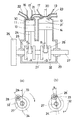
以下、この発明の実施の形態を図面を参照して説明する。図1は第1実施形態のピストン形内燃機関の主要断面図である。図示のように、シリンダ及びピストンは圧縮シリンダ11と膨張シリンダ12、及び各シリンダに摺動自在に嵌合するピストン13、14とから成り、両シリンダはクランクケース29に一体に取り付けられ、全体でエンジンを形成している。膨張シリンダ12は、図示のように、圧縮シリンダ11とストロークが同一であり、かつ圧縮シリンダ11の圧縮比より大きい所望の膨張比(例えば圧縮比8.5に対して膨張比16)の体積となるような径のシリンダとして形成されている。
【0013】
膨張シリンダ12の上部には燃焼室15が設けられており、シリンダ11、12の上方に形成されるシリンダ室30、31への気体の流入、送出を制御するための吸入弁16、送出弁17’(送出弁17’は省略されることもある)、17、膨張弁18、排気弁19が対応する各シリンダ11、12に対して設けられている。20は点火プラグである。なお、この実施形態の内燃機関はガソリンエンジンとして説明するが、ディーゼルエンジンとして応用するときは点火プラグ20は燃料噴射ノズル20’に代えるものとする。
【0014】
燃焼室15と圧縮シリンダ11とは連結管21により連結し、圧縮シリンダ11のシリンダ室30で圧縮された混合気を燃焼室15へ導入するようにしている。又、圧縮シリンダ11の上端には混合気を供給する吸入管22が接続され、膨張シリンダ12の上端には排気管23が接続されている。ディーゼルエンジンとして用いるときは吸入管22から混合気に代えてエアーが供給される。各シリンダ11、12の下方にはクランクケース29内にクランク32、クランク軸28が取付けられ、コンロッド24、25によりピストン13、14とそれぞれ連結され、クランクケース29から突出するように出力軸27、外部にフライホイール26が設けられている。
【0015】
上記の構成としたこの実施形態のエンジンの作用は次の通りである。説明の都合上始動後の通常運転に入り圧縮シリンダ11で圧縮が始まる直前から説明する。圧縮が始まる前の行程で吸入弁16を開き混合気がシリンダ室30に給気されているものとする。クランク軸28が回転してピストン13、14が上昇する直前に吸入弁16は閉じられ、送出弁17’、17は開とされ、膨張弁18は閉、排気弁19は開とされる。
【0016】
この状態からピストン13、14が上昇を始めると、圧縮シリンダ11ではシリンダ室30の混合気は圧縮されて圧力が上昇し燃焼室15へ圧入される。一方、膨張シリンダ12では排気弁19が開いているためシリンダ12内の膨張後の排気はピストン14の上昇により排気弁19を通り排気管23を経て外部へ排出される。
【0017】
上記ピストン13、14の上昇によりそれぞれが上死点に達した後下降に転じる際に、送出弁17’、17は閉、膨張弁18は開、排気弁19は閉となり、点火プラグ20の点火により燃焼室15内の混合気が爆発してピストン14を押し下げる。ディーゼルエンジンの場合は燃料噴射ノズル20’の燃料噴射により燃焼、膨張してピストン14を押し下げる。
【0018】
このピストン14の下降に連動してピストン13も下降し、その際吸入弁16が開かれて混合気が吸入される。その後は上記1サイクルの動作が連続して繰り返され、その駆動力はクランク32を介して回転力に転換され出力軸27により出力される。なお、上記サイクルは圧縮と排気、爆発(膨張)と吸入の行程がクランク軸の1回転で行なわれるから、このエンジンは掃気作用を要しない新形の2サイクルエンジンとなり、従来型の同一出力の4サイクルの2シリンダエンジンとシリンダの単位容積当りの出力は大差ない程度となる。
【0019】
上記の作用でエンジンが動力を発生する際の熱効率は高効率となるが、その理由について説明する。図3に従来形のガソリンエンジンとこの実施形態のエンジン(以下DCエンジンという)の理論熱効率を計算するためのPV線図を示す。(a)図は従来形、(b)図はDCエンジンのものである。但し、理解し易くするため、(b)図では膨張シリンダ12の内径を圧縮シリンダ11と同一と仮定し、膨張比が圧縮比より大きいことを膨張比に比例するシリンダストロークS2 のシリンダに置き換えて示している。
【0020】
従来形のエンジンに比較すると、図3の(b)図において、1’→1→4→4’の面積に相当する出力エネルギーを回収したこととなり、その分だけ熱効率の向上に寄与する。但し、実際には発生した熱量の全てが軸馬力として利用できる訳ではなく、平均有効圧力や正味平均有効圧力を考慮した仕事量しか転換されないから、実際の熱効率は上記より低くなるが、理論熱効率が大きいということは実際に有効に得られる動力もそれだけ大きくなることを意味しており、熱効率が大きく改善されるという結果に変わりはない。
【0021】
なお、上記説明では理論熱効率が向上する作用を圧縮シリンダと同一径でストロークが長い膨張シリンダを用いて説明したが、図1の例では反対にピストンのストロークが圧縮シリンダと膨張シリンダで同一であり、かつ膨張シリンダの径が所望の膨張比となるように圧縮シリンダの径より大きいものとされており、作用の説明は図示の実施形態のエンジンの構成とは異なる。しかし、膨張シリンダの体積が圧縮シリンダより大きい点では同じであり、理解し易く図示するためにストロークの長い例で作用の説明をした。
【0022】
従って、膨張シリンダの体積が圧縮シリンダより大きい例として、第1実施形態とは反対に膨張シリンダと圧縮シリンダの径を同一とし、膨張シリンダのストロークを長くするようにしてもよい。あるいは、膨張シリンダのストローク及びシリンダ径のいずれをも圧縮シリンダより大きいものとして設定してもよい。
【0023】
図4に第2実施形態のピストン形内燃機関の主要断面図を示す。この実施形態のエンジンは、第1実施形態のものに比して、独立した燃焼室15と膨張弁18を省略した点が異なっている。独立の燃焼室15を省略したため膨張シリンダ12のピストン14より上方のシリンダ室31’が燃焼室として用いられる。又、独立の燃焼室15がないため圧縮シリンダ11のシリンダ室30を連結管21により直接膨張シリンダ12のシリンダ室31’に連結している。
【0024】
又、(a)図、(b)図に示すように、膨張シリンダ12のピストン14のクランク軸28’が上死点33の手前付近で位相角αの位置にあるとき、圧縮シリンダ1のピストン13のクランク軸28は上死点33の手前で位相角2αの位置にくるようにクランク軸28と28’の取付角度を互いに角度αだけずらして、即ちクランクの矢印fの回転方向に対してクランク軸28’を28より位相角度α進み角となるように取り付けられている。その理由については後で説明する。その他の構成については第1実施形態と同様であり、同一機能部材については同一符号を付して詳細な説明を省略する。
【0025】
上記構成のこの実施形態のエンジンの作用も、基本的には第1実施形態と同様であり、従来形の単一シリンダのエンジンに比して高効率な出力を得ることができるが、この実施形態ではさらに次のような有利な作用が得られる。以下、その有利な作用について図5A、図5Bを参照して説明する。
【0026】
説明の都合上圧縮及び排気行程から説明する。図5Aの(a)図に示すように、クランク軸28、28’の回転と共にピストン13、14が下方位置から上昇して圧縮、排気行程が始まると、その行程の始まる直前に吸入弁16は閉、送出弁17’、17も閉、排気弁19は開とされ、ピストン13、14の上昇により圧縮シリンダ11では圧縮、膨張シリンダ12では排気が行なわれる。
【0027】
上記圧縮、排気行程の終わる少し手前までピストン13、14が上昇して、クランク軸28’が上死点33の手前の位相角α、28が位相角2αの位置に来たとき、(b)図に示すように、ピストン14の上端が上死点よりXだけ手前の高さに、ピストン13の上端が上死点よりYだけ手前の高さ位置にあるとする。この状態位置までピストン13、14が上昇する間に圧縮シリンダ11では所望の圧縮比に混合気は十分圧縮され、排気も大部分は終わりに近づいている。
【0028】
このとき送出弁17’、17を開放し、排気弁19を閉じると、圧縮シリンダ11のシリンダ室30で圧縮された混合気は連結管21を介して膨張シリンダ12のシリンダ室31’(燃焼室)へ送り込まれる。なお、吸入弁16は閉じたままとする。そして、さらにピストン13、14が上昇し、図5Bの(c)図に示すように、ピストン13の上端が上死点まで上昇すると、その間に進み角に設けられているクランク軸28’に連結されたピストン14は既に上死点を通過し、先の上死点手前の距離Xと同じ距離だけ下降している。
【0029】
このようにピストン13が上死点に達しかつピストン14が距離Xだけ下降した時点で、送出弁17’、17を閉じ、点火プラグ20の点火により混合気を爆発させると、その爆発による圧力の急激な上昇でピストン14が押圧されて(d)図に示すように下降し、シリンダ室31’(燃焼室)が体積膨張する。このピストン14の下降に連動してピストン13も下降するが、その下降の始まる際に吸入弁16を開いて吸入管22から混合気が吸入される。
【0030】
以上から、この実施形態のエンジンの基本作用は第1実施形態と同様に2サイクルエンジンとして作用することが分かるが、この実施形態では図5Aの(b)図から図5Bの(c)図において説明したように、膨張シリンダ12のピストン14が上死点近くに上昇し、圧縮シリンダ11のピストン13の上昇距離より小さい範囲でさらに上昇して上死点からさらに下降側の距離Xだけ下降する容積変動の少ない間に排気を充分行なった残留排気の少ない状態で圧縮シリンダ11から圧縮された混合気が送り込まれる。
【0031】
このため、膨張シリンダ12のシリンダ室31’(燃焼室)での混合気の爆発、燃焼が十分に行なわれる。又、図1の燃焼室15及び膨張弁18が設けられていないので製作が容易であり、かつ膨張シリンダ12の上部のシリンダ室31’は燃焼室を兼用しているためピストン14が最も上昇したとき上部に残る残留排気が少なく、容積変動の少ない動作時間中に圧縮された混合気を圧入することができる。
【0032】
以上のように、各実施形態のエンジンをガソリンエンジンとして利用した場合、圧縮比が従来例と同様に低圧縮比とすることができるためノッキングを起こさず、膨張比は大きく設定できるため、熱効率が高効率となり、CO2 の削減及び燃費の節減となる。
【0033】
ディーゼルエンジンとして利用する場合は、圧縮シリンダが膨張シリンダと別になっているので、給気を高温の膨張シリンダを通すことなく単独に圧縮シリンダで冷却できるので、給気冷却が容易であり、給気冷却の結果燃焼温度が低下し、NOxの発生を抑制することができる。又、燃焼による膨張シリンダの温度上昇を低くすることにより燃料の約30%を占める冷却損失を低減し、又膨張比を大きくすることにより排気のエネルギーを回収し、熱効率の向上、即ち燃費の低減となる。
【0034】
従来形のエンジンではシリンダを断熱化しても給気が熱され、熱効率の向上の効果は少ないが、上記実施形態では圧縮シリンダが膨張シリンダと分離しているため直接吸気を加熱せず、従って断熱化が有効となり、冷却損失が減少し、熱効率の向上となる。
【0035】
【発明の効果】
以上、詳細に説明したように、この発明のピストン形内燃機関はシリンダを圧縮シリンダと膨張シリンダとに分離して設け、膨張比を圧縮比より大きい所望の値に設定したものとしたから、従来形ではシリンダが1つであるため、圧縮比を大きくすると必然的に膨張比も大きくなり、熱効率は向上するが圧縮比を所定以上に大きくするとガソリンエンジンではノッキングを起こし、ディーゼルエンジンでは燃焼温度が高くなり有害NOX の発生が多くなり、冷却損失が大きくなるなどの不都合を避けることができないのに対して、本発明では圧縮比を小さくすることにより上記不都合を抑制し、一方膨張比は大きく設定することにより熱効率を大きく向上させることができるという画期的な効果を達成できる。
【図面の簡単な説明】
【図1】第1実施形態のピストン形内燃機関の主要断面図
【図2】同上の内燃機関の作用の説明図
【図3】同上の内燃機関と従来形の内燃機関のPV線図
【図4】第2実施形態のピストン形内燃機関の主要断面図
【図5A】同上の内燃機関の作用の説明図
【図5B】同上の内燃機関の作用の説明図
【符号の説明】
11 圧縮シリンダ
12 膨張入り
13、14 ピストン
15 燃焼室
16 吸入弁
17’、17 送出弁
18 膨張弁
19 排気弁
20 点火プラグ
21 連結管
22 吸入管
23 排気管
24、25 コンロッド
26 フライホイール
27 出力軸
28、28’ クランク軸
29 クランクケース
30、31 シリンダ室
31’ シリンダ室
32 クランク[0001]
BACKGROUND OF THE INVENTION
The present invention relates to a piston-type internal combustion engine that converts a movement of a piston that linearly moves in a cylinder by an explosive force of fuel into a rotational movement.
[0002]
[Prior art]
For a long time, gasoline engines and diesel engines have been widely used as piston-type internal combustion engines that convert the movement of a piston that linearly moves in a cylinder by detonating fuel such as gasoline into a rotary motion. As is well known, a gasoline engine is a type in which a mixture of vaporized fuel and air is sent to a cylinder and ignited by a spark plug to cause an explosion in the cylinder. A diesel engine is subjected to high compression in the cylinder. In this type of fuel, high-pressure fuel is injected into the air at a high temperature by a fuel injection pump to cause explosion by spontaneous ignition.
[0003]
The above engine is typically a four-cycle engine in which four strokes of intake, compression, explosion (expansion), and exhaust are taken as one cycle and the crankshaft is rotated twice, that is, with four strokes of the piston. Therefore, it is assumed that the above four strokes are performed by one piston slidably fitted in one cylinder. For this reason, the compression ratio and the expansion ratio are necessarily the same with respect to the movement stroke when the piston moves. Moreover, the compression ratio of a gasoline engine is generally about 7 to 10, and about 12 to 22 for a diesel engine.
[0004]
[Problems to be solved by the invention]
By the way, the compression ratio of the gasoline engine is generally set to the above-mentioned value, and if this value is increased, the thermal efficiency is theoretically improved. However, if this value is set to 12 or more, knocking may not be used and the compression is temporarily performed. Even if the ratio can be made larger than that range, it is only slightly improved and it is difficult to greatly improve the thermal efficiency. It is preferable that the diesel engine does not cause knocking due to an increase in the compression ratio, but rather has a high compression ratio in view of only preventing knocking.
[0005]
However, diesel knock may occur due to the delay in ignition of the fuel. For this reason, as described above, the combustion temperature is high, harmful NOx is often generated, and it is difficult to completely suppress this. There is. Various problems associated with each of the ignition combustion systems as described above are caused by performing four strokes of suction, compression, explosion (expansion), and exhaust in one cylinder. In particular, the compression ratio and the expansion ratio are inevitably the same because the compression and expansion strokes are performed by one cylinder even though the required performance is different.
[0006]
On the other hand, in the conventional piston type internal combustion engine described above, since the number of cylinders is one for four strokes by the piston, it is difficult to cool the intake air mixture or the air supply. The compressed supply air rises rapidly in the explosion (expansion) process, and even if a cooling means is installed around the actual cylinder, it is supplied to the same cylinder without being sufficiently cooled by this cooling means alone. This is because the temperature of the air supply inevitably increases because the air is inhaled.
[0007]
A piston engine that can supply and cool air and can suppress the generation of NOx is desired. In this case, if the compression and expansion are performed in different cylinders, at least air supply cooling can be easier than in the past. However, a piston-type internal combustion engine that performs compression and expansion using different cylinders has been attempted due to cost advantages commensurate with air supply cooling. There are no known examples.
[0008]
In the present invention, it is noted that there is a limit in improving the thermal efficiency of the conventional piston type internal combustion engine with a single cylinder, the engine is separated into a compression cylinder and an expansion cylinder, and the compression ratio and the expansion ratio are made different. It is an object of the present invention to provide a piston-type internal combustion engine that can greatly improve thermal efficiency.
[0009]
[Means for Solving the Problems]
As a means for solving the above-described problems, the present invention expands a cylinder of a piston-type internal combustion engine that outputs a rotational force by driving a piston slidably fitted in the cylinder with an explosive force of fuel and a compression cylinder. The cylinder is separated from the cylinder, and both cylinders are connected by a connecting pipe. The volume of the expansion cylinder is larger than that of the compression cylinder so that the expansion ratio is larger than the compression ratio. The piston-type internal combustion engine is configured such that the output shaft is rotationally driven by the piston of the expansion cylinder.
[0010]
In the invention with the above configuration, the expansion cylinder and the compression cylinder are provided separately, and the expansion ratio is set to be larger than the compression ratio. Therefore, the air-fuel mixture sucked and compressed during one rotation of the crankshaft explodes and expands. In this case, it expands at an expansion ratio larger than the compression ratio. In the meantime, the larger the expansion ratio, the greater the energy from the explosion is converted into motive power, thus significantly improving the thermal efficiency.
[0011]
Also, since the compression cylinder of the engine is provided separately from the expansion cylinder, even if the fuel explodes and expands in the expansion cylinder and the expansion cylinder becomes hot, the heating temperature does not move to the compression cylinder. Accordingly, the temperature rise of the compression cylinder is suppressed without being affected by the heat from the expansion cylinder. When used as a diesel engine, the temperature rise caused by compressing the intake air at a high compression ratio in the compression cylinder is effectively suppressed by providing the cooling means in the compression cylinder, and therefore the generation of harmful NOx is also reduced.
[0012]
Embodiment
Embodiments of the present invention will be described below with reference to the drawings. FIG. 1 is a main cross-sectional view of the piston-type internal combustion engine of the first embodiment. As shown in the figure, the cylinder and the piston are composed of a
[0013]
A
[0014]
The
[0015]
The operation of the engine of this embodiment configured as described above is as follows. For convenience of explanation, the operation will be described from immediately before the start of compression in the
[0016]
When the
[0017]
When the
[0018]
In conjunction with the lowering of the
[0019]
The thermal efficiency when the engine generates power by the above action is high efficiency. The reason will be described. FIG. 3 shows a PV diagram for calculating the theoretical thermal efficiency of the conventional gasoline engine and the engine of this embodiment (hereinafter referred to as DC engine). (A) A figure is a conventional type, (b) A figure is a thing of DC engine. However, for ease of understanding, replaced by (b) the inner diameter of the
[0020]
Compared to the conventional form of the engine, in (b) of FIG 3, 1 '→ 1 → 4 → 4' corresponds to the area of will be to recover the output energy, that contribute to the improvement of the thermal efficiency by that amount. However , in reality, not all of the generated heat can be used as axial horsepower, and only the amount of work taking into account the average effective pressure and net average effective pressure is converted, so the actual thermal efficiency is lower than the above, but the theoretical thermal efficiency A large value means that the power that can be actually obtained effectively increases accordingly, and the thermal efficiency is greatly improved.
[0021]
In the above description, the theoretical thermal efficiency has been improved by using an expansion cylinder having the same diameter and a long stroke as the compression cylinder. However, in the example of FIG. 1, the piston stroke is the same in the compression cylinder and the expansion cylinder. In addition, the diameter of the expansion cylinder is made larger than the diameter of the compression cylinder so as to obtain a desired expansion ratio, and the description of the action is different from the configuration of the engine of the illustrated embodiment. However, it is the same in that the volume of the expansion cylinder is larger than that of the compression cylinder, and the operation has been described with an example of a long stroke for easy understanding.
[0022]
Therefore, as an example in which the volume of the expansion cylinder is larger than that of the compression cylinder, the diameters of the expansion cylinder and the compression cylinder may be the same as in the first embodiment, and the stroke of the expansion cylinder may be increased. Alternatively, both the stroke of the expansion cylinder and the cylinder diameter may be set larger than the compression cylinder.
[0023]
FIG. 4 shows a main cross-sectional view of the piston type internal combustion engine of the second embodiment. The engine of this embodiment is different from that of the first embodiment in that the
[0024]
When the crankshaft 28 'of the
[0025]
The operation of the engine of this embodiment having the above-described configuration is basically the same as that of the first embodiment, and a high-efficiency output can be obtained as compared with a conventional single cylinder engine. In the embodiment, the following advantageous effects can be obtained. The advantageous operation will be described below with reference to FIGS. 5A and 5B.
[0026]
For convenience of explanation, explanation will be given from the compression and exhaust strokes. As shown in FIG. 5A (a), when the
[0027]
When the
[0028]
At this time, when the
[0029]
Thus, when the
[0030]
From the above, it can be seen that the basic operation of the engine of this embodiment acts as a two-cycle engine as in the first embodiment. In this embodiment, in FIGS. 5B to 5C, FIG. As described, the
[0031]
For this reason, the explosion and combustion of the air-fuel mixture in the
[0032]
As described above, when the engine of each embodiment is used as a gasoline engine, the compression ratio can be set to a low compression ratio as in the conventional example, so that knocking does not occur and the expansion ratio can be set large. High efficiency, CO 2 reduction and fuel economy.
[0033]
When using as a diesel engine, the compression cylinder is separate from the expansion cylinder, so the supply air can be cooled by the compression cylinder alone without passing through the high-temperature expansion cylinder. As a result of the cooling, the combustion temperature decreases, and the generation of NOx can be suppressed. Also, by reducing the temperature rise of the expansion cylinder due to combustion, the cooling loss occupying about 30% of the fuel is reduced, and by increasing the expansion ratio, the exhaust energy is recovered, improving the thermal efficiency, that is, reducing the fuel consumption. It becomes.
[0034]
In the conventional engine, even if the cylinder is insulated, the supply air is heated and the effect of improving the thermal efficiency is small. However, in the above embodiment, since the compression cylinder is separated from the expansion cylinder, the intake air is not directly heated. Is effective, cooling loss is reduced, and thermal efficiency is improved.
[0035]
【The invention's effect】
As described above in detail, the piston-type internal combustion engine of the present invention is provided with the cylinder separated into the compression cylinder and the expansion cylinder, and the expansion ratio is set to a desired value larger than the compression ratio. Since there is only one cylinder in the form, increasing the compression ratio inevitably increases the expansion ratio, improving the thermal efficiency. However, if the compression ratio is increased beyond a predetermined level, the gasoline engine knocks, and the diesel engine has a combustion temperature higher than that. higher becomes the more the generation of harmful nO X, whereas it is impossible to avoid the inconvenience such as the cooling loss increases, the present invention suppresses the disadvantage by reducing the compression ratio, whereas the expansion ratio is greater By setting, an epoch-making effect that the thermal efficiency can be greatly improved can be achieved.
[Brief description of the drawings]
FIG. 1 is a main cross-sectional view of a piston-type internal combustion engine of a first embodiment. FIG. 2 is an explanatory view of the operation of the internal combustion engine. FIG. 4] Main sectional view of piston type internal combustion engine of the second embodiment [FIG. 5A] Explanatory view of the operation of the internal combustion engine of the above [FIG. 5B] Explanatory view of the operation of the internal combustion engine of the above [Description of reference numerals]
DESCRIPTION OF
Claims (1)
Priority Applications (1)
| Application Number | Priority Date | Filing Date | Title |
|---|---|---|---|
| JP2000038581A JP4286419B2 (en) | 2000-02-16 | 2000-02-16 | Piston type internal combustion engine |
Applications Claiming Priority (1)
| Application Number | Priority Date | Filing Date | Title |
|---|---|---|---|
| JP2000038581A JP4286419B2 (en) | 2000-02-16 | 2000-02-16 | Piston type internal combustion engine |
Publications (3)
| Publication Number | Publication Date |
|---|---|
| JP2001227368A JP2001227368A (en) | 2001-08-24 |
| JP2001227368A5 JP2001227368A5 (en) | 2007-02-15 |
| JP4286419B2 true JP4286419B2 (en) | 2009-07-01 |
Family
ID=18562294
Family Applications (1)
| Application Number | Title | Priority Date | Filing Date |
|---|---|---|---|
| JP2000038581A Expired - Fee Related JP4286419B2 (en) | 2000-02-16 | 2000-02-16 | Piston type internal combustion engine |
Country Status (1)
| Country | Link |
|---|---|
| JP (1) | JP4286419B2 (en) |
Families Citing this family (10)
| Publication number | Priority date | Publication date | Assignee | Title |
|---|---|---|---|---|
| GB0617726D0 (en) | 2006-09-08 | 2006-10-18 | Atalla Naji A | Device (modifications) to improve efficiency of internal combustion engines |
| MX2009011292A (en) * | 2007-08-07 | 2009-10-30 | Scuderi Group Llc | Split-cycle engine with early crossover compression valve opening. |
| CA2696377A1 (en) * | 2007-08-13 | 2009-02-19 | Scuderi Group Llc | Pressure balanced engine valves |
| US8151747B2 (en) * | 2009-04-07 | 2012-04-10 | Scuderi Group, Llc | Crescent-shaped recess in piston of a split-cycle engine |
| HUE026544T2 (en) * | 2009-06-29 | 2016-06-28 | Jenoe Polgar | Internal combustion engine with separate combustion chamber and a method to achieve modified and controlled autoignition in said chamber |
| ITPI20090117A1 (en) * | 2009-09-23 | 2011-03-23 | Roberto Gentili | SPONTANEOUS IGNITION ENGINE WITH PROGRESSIVE LOAD ENTRY IN THE COMBUSTION PHASE |
| JP2014515068A (en) * | 2010-09-29 | 2014-06-26 | スクデリ グループ インコーポレイテッド | Crossover passage sized for split-cycle engines |
| US8833315B2 (en) | 2010-09-29 | 2014-09-16 | Scuderi Group, Inc. | Crossover passage sizing for split-cycle engine |
| JP6494662B2 (en) * | 2014-01-20 | 2019-04-03 | ツアー エンジン インコーポレーティッド | Variable volume transfer shuttle capsule and valve mechanism |
| WO2017052207A1 (en) * | 2015-09-22 | 2017-03-30 | 조주혁 | Two-stroke-cycle internal combustion engine supplying air using air compressing device outside engine |
-
2000
- 2000-02-16 JP JP2000038581A patent/JP4286419B2/en not_active Expired - Fee Related
Also Published As
| Publication number | Publication date |
|---|---|
| JP2001227368A (en) | 2001-08-24 |
Similar Documents
| Publication | Publication Date | Title |
|---|---|---|
| US5103645A (en) | Internal combustion engine and method | |
| CA2433433C (en) | Eight-stroke internal combustion engine utilizing a slave cylinder | |
| US6095100A (en) | Combination internal combustion and steam engine | |
| US7273023B2 (en) | Steam enhanced double piston cycle engine | |
| KR20080011162A (en) | Double piston cycle engine | |
| US3959974A (en) | Internal combustion engine | |
| JP4286419B2 (en) | Piston type internal combustion engine | |
| JP2010285977A (en) | Built-in compressor type six-stroke engine exclusive for hydrogen | |
| US6314925B1 (en) | Two-stroke internal combustion engine with recuperator in cylinder head | |
| CA1209925A (en) | Internal combustion engine and operating cycle | |
| US8353159B2 (en) | Combustion engine with heat recovery system | |
| WO2007088560A1 (en) | An improved hybrid internal combustion engine with extended expansion | |
| JP4951143B1 (en) | Three-output shaft type internal combustion engine | |
| GB2481980A (en) | I.c. engine in which water is recovered from the exhaust and re-used | |
| JPH0338410Y2 (en) | ||
| JP5002721B1 (en) | Operating gas generator | |
| JPH0759888B2 (en) | Water-injected adiabatic ceramic diesel engine | |
| Jangalwa et al. | Scuderi Split Cycle Engine: A Review | |
| US6941903B2 (en) | System and method for adding air to an explosion chamber in an engine cylinder | |
| RU2167315C2 (en) | Thermodynamic cycle for internal combustion engine and device for executing the cycle | |
| KR20080038273A (en) | Steam enhanced double piston cycle engine | |
| EP1528234B1 (en) | Eight-stroke internal combustion engine utilizing a slave cylinder | |
| CN1934341A (en) | Method for making internal combustion engine super expansion working and low-temperature exhausting and reciprocating circulating internal combusion engine | |
| GB2312475A (en) | Internal combustion and steam engine | |
| JPS61190125A (en) | Complete expansion type internal-combustion engine |
Legal Events
| Date | Code | Title | Description |
|---|---|---|---|
| A521 | Written amendment |
Free format text: JAPANESE INTERMEDIATE CODE: A523 Effective date: 20061227 |
|
| A621 | Written request for application examination |
Free format text: JAPANESE INTERMEDIATE CODE: A621 Effective date: 20061227 |
|
| A131 | Notification of reasons for refusal |
Free format text: JAPANESE INTERMEDIATE CODE: A131 Effective date: 20080819 |
|
| A521 | Written amendment |
Free format text: JAPANESE INTERMEDIATE CODE: A523 Effective date: 20081017 |
|
| A131 | Notification of reasons for refusal |
Free format text: JAPANESE INTERMEDIATE CODE: A131 Effective date: 20081202 |
|
| A521 | Written amendment |
Free format text: JAPANESE INTERMEDIATE CODE: A523 Effective date: 20090130 |
|
| TRDD | Decision of grant or rejection written | ||
| A01 | Written decision to grant a patent or to grant a registration (utility model) |
Free format text: JAPANESE INTERMEDIATE CODE: A01 Effective date: 20090317 |
|
| A01 | Written decision to grant a patent or to grant a registration (utility model) |
Free format text: JAPANESE INTERMEDIATE CODE: A01 |
|
| A61 | First payment of annual fees (during grant procedure) |
Free format text: JAPANESE INTERMEDIATE CODE: A61 Effective date: 20090325 |
|
| FPAY | Renewal fee payment (event date is renewal date of database) |
Free format text: PAYMENT UNTIL: 20120403 Year of fee payment: 3 |
|
| R150 | Certificate of patent or registration of utility model |
Free format text: JAPANESE INTERMEDIATE CODE: R150 |
|
| FPAY | Renewal fee payment (event date is renewal date of database) |
Free format text: PAYMENT UNTIL: 20120403 Year of fee payment: 3 |
|
| FPAY | Renewal fee payment (event date is renewal date of database) |
Free format text: PAYMENT UNTIL: 20130403 Year of fee payment: 4 |
|
| FPAY | Renewal fee payment (event date is renewal date of database) |
Free format text: PAYMENT UNTIL: 20130403 Year of fee payment: 4 |
|
| FPAY | Renewal fee payment (event date is renewal date of database) |
Free format text: PAYMENT UNTIL: 20140403 Year of fee payment: 5 |
|
| LAPS | Cancellation because of no payment of annual fees |