EP2447464B1 - Transportsystem für durchgehende Stangen - Google Patents
Transportsystem für durchgehende Stangen Download PDFInfo
- Publication number
- EP2447464B1 EP2447464B1 EP11186976.4A EP11186976A EP2447464B1 EP 2447464 B1 EP2447464 B1 EP 2447464B1 EP 11186976 A EP11186976 A EP 11186976A EP 2447464 B1 EP2447464 B1 EP 2447464B1
- Authority
- EP
- European Patent Office
- Prior art keywords
- rod
- reel
- transport
- trailer
- unit
- Prior art date
- Legal status (The legal status is an assumption and is not a legal conclusion. Google has not performed a legal analysis and makes no representation as to the accuracy of the status listed.)
- Active
Links
Images


Classifications
-
- B—PERFORMING OPERATIONS; TRANSPORTING
- B60—VEHICLES IN GENERAL
- B60P—VEHICLES ADAPTED FOR LOAD TRANSPORTATION OR TO TRANSPORT, TO CARRY, OR TO COMPRISE SPECIAL LOADS OR OBJECTS
- B60P3/00—Vehicles adapted to transport, to carry or to comprise special loads or objects
- B60P3/035—Vehicles adapted to transport, to carry or to comprise special loads or objects for transporting reel units
-
- B—PERFORMING OPERATIONS; TRANSPORTING
- B21—MECHANICAL METAL-WORKING WITHOUT ESSENTIALLY REMOVING MATERIAL; PUNCHING METAL
- B21C—MANUFACTURE OF METAL SHEETS, WIRE, RODS, TUBES, PROFILES OR LIKE SEMI-MANUFACTURED PRODUCTS OTHERWISE THAN BY ROLLING; AUXILIARY OPERATIONS USED IN CONNECTION WITH METAL-WORKING WITHOUT ESSENTIALLY REMOVING MATERIAL
- B21C47/00—Winding-up, coiling or winding-off metal wire, metal band or other flexible metal material characterised by features relevant to metal processing only
- B21C47/02—Winding-up or coiling
- B21C47/04—Winding-up or coiling on or in reels or drums, without using a moving guide
-
- B—PERFORMING OPERATIONS; TRANSPORTING
- B21—MECHANICAL METAL-WORKING WITHOUT ESSENTIALLY REMOVING MATERIAL; PUNCHING METAL
- B21C—MANUFACTURE OF METAL SHEETS, WIRE, RODS, TUBES, PROFILES OR LIKE SEMI-MANUFACTURED PRODUCTS OTHERWISE THAN BY ROLLING; AUXILIARY OPERATIONS USED IN CONNECTION WITH METAL-WORKING WITHOUT ESSENTIALLY REMOVING MATERIAL
- B21C47/00—Winding-up, coiling or winding-off metal wire, metal band or other flexible metal material characterised by features relevant to metal processing only
- B21C47/24—Transferring coils to or from winding apparatus or to or from operative position therein; Preventing uncoiling during transfer
-
- B—PERFORMING OPERATIONS; TRANSPORTING
- B21—MECHANICAL METAL-WORKING WITHOUT ESSENTIALLY REMOVING MATERIAL; PUNCHING METAL
- B21C—MANUFACTURE OF METAL SHEETS, WIRE, RODS, TUBES, PROFILES OR LIKE SEMI-MANUFACTURED PRODUCTS OTHERWISE THAN BY ROLLING; AUXILIARY OPERATIONS USED IN CONNECTION WITH METAL-WORKING WITHOUT ESSENTIALLY REMOVING MATERIAL
- B21C47/00—Winding-up, coiling or winding-off metal wire, metal band or other flexible metal material characterised by features relevant to metal processing only
- B21C47/28—Drums or other coil-holders
-
- B—PERFORMING OPERATIONS; TRANSPORTING
- B65—CONVEYING; PACKING; STORING; HANDLING THIN OR FILAMENTARY MATERIAL
- B65H—HANDLING THIN OR FILAMENTARY MATERIAL, e.g. SHEETS, WEBS, CABLES
- B65H49/00—Unwinding or paying-out filamentary material; Supporting, storing or transporting packages from which filamentary material is to be withdrawn or paid-out
- B65H49/38—Skips, cages, racks, or containers, adapted solely for the transport or storage of bobbins, cops, or the like
-
- B—PERFORMING OPERATIONS; TRANSPORTING
- B65—CONVEYING; PACKING; STORING; HANDLING THIN OR FILAMENTARY MATERIAL
- B65H—HANDLING THIN OR FILAMENTARY MATERIAL, e.g. SHEETS, WEBS, CABLES
- B65H75/00—Storing webs, tapes, or filamentary material, e.g. on reels
- B65H75/02—Cores, formers, supports, or holders for coiled, wound, or folded material, e.g. reels, spindles, bobbins, cop tubes, cans, mandrels or chucks
- B65H75/18—Constructional details
- B65H75/20—Skeleton construction, e.g. formed of wire
-
- B—PERFORMING OPERATIONS; TRANSPORTING
- B65—CONVEYING; PACKING; STORING; HANDLING THIN OR FILAMENTARY MATERIAL
- B65H—HANDLING THIN OR FILAMENTARY MATERIAL, e.g. SHEETS, WEBS, CABLES
- B65H75/00—Storing webs, tapes, or filamentary material, e.g. on reels
- B65H75/02—Cores, formers, supports, or holders for coiled, wound, or folded material, e.g. reels, spindles, bobbins, cop tubes, cans, mandrels or chucks
- B65H75/18—Constructional details
- B65H75/22—Constructional details collapsible; with removable parts
- B65H75/2218—Collapsible hubs
- B65H75/2227—Collapsible hubs with a flange fixed to the hub part
-
- B—PERFORMING OPERATIONS; TRANSPORTING
- B65—CONVEYING; PACKING; STORING; HANDLING THIN OR FILAMENTARY MATERIAL
- B65H—HANDLING THIN OR FILAMENTARY MATERIAL, e.g. SHEETS, WEBS, CABLES
- B65H75/00—Storing webs, tapes, or filamentary material, e.g. on reels
- B65H75/02—Cores, formers, supports, or holders for coiled, wound, or folded material, e.g. reels, spindles, bobbins, cop tubes, cans, mandrels or chucks
- B65H75/34—Cores, formers, supports, or holders for coiled, wound, or folded material, e.g. reels, spindles, bobbins, cop tubes, cans, mandrels or chucks specially adapted or mounted for storing and repeatedly paying-out and re-storing lengths of material provided for particular purposes, e.g. anchored hoses, power cables
- B65H75/36—Cores, formers, supports, or holders for coiled, wound, or folded material, e.g. reels, spindles, bobbins, cop tubes, cans, mandrels or chucks specially adapted or mounted for storing and repeatedly paying-out and re-storing lengths of material provided for particular purposes, e.g. anchored hoses, power cables without essentially involving the use of a core or former internal to a stored package of material, e.g. with stored material housed within casing or container, or intermittently engaging a plurality of supports as in sinuous or serpentine fashion
- B65H75/362—Cores, formers, supports, or holders for coiled, wound, or folded material, e.g. reels, spindles, bobbins, cop tubes, cans, mandrels or chucks specially adapted or mounted for storing and repeatedly paying-out and re-storing lengths of material provided for particular purposes, e.g. anchored hoses, power cables without essentially involving the use of a core or former internal to a stored package of material, e.g. with stored material housed within casing or container, or intermittently engaging a plurality of supports as in sinuous or serpentine fashion with stored material housed within a casing or container
- B65H75/364—Cores, formers, supports, or holders for coiled, wound, or folded material, e.g. reels, spindles, bobbins, cop tubes, cans, mandrels or chucks specially adapted or mounted for storing and repeatedly paying-out and re-storing lengths of material provided for particular purposes, e.g. anchored hoses, power cables without essentially involving the use of a core or former internal to a stored package of material, e.g. with stored material housed within casing or container, or intermittently engaging a plurality of supports as in sinuous or serpentine fashion with stored material housed within a casing or container the stored material being coiled
-
- B—PERFORMING OPERATIONS; TRANSPORTING
- B65—CONVEYING; PACKING; STORING; HANDLING THIN OR FILAMENTARY MATERIAL
- B65H—HANDLING THIN OR FILAMENTARY MATERIAL, e.g. SHEETS, WEBS, CABLES
- B65H75/00—Storing webs, tapes, or filamentary material, e.g. on reels
- B65H75/02—Cores, formers, supports, or holders for coiled, wound, or folded material, e.g. reels, spindles, bobbins, cop tubes, cans, mandrels or chucks
- B65H75/34—Cores, formers, supports, or holders for coiled, wound, or folded material, e.g. reels, spindles, bobbins, cop tubes, cans, mandrels or chucks specially adapted or mounted for storing and repeatedly paying-out and re-storing lengths of material provided for particular purposes, e.g. anchored hoses, power cables
- B65H75/38—Cores, formers, supports, or holders for coiled, wound, or folded material, e.g. reels, spindles, bobbins, cop tubes, cans, mandrels or chucks specially adapted or mounted for storing and repeatedly paying-out and re-storing lengths of material provided for particular purposes, e.g. anchored hoses, power cables involving the use of a core or former internal to, and supporting, a stored package of material
- B65H75/44—Constructional details
- B65H75/4402—Guiding arrangements to control paying-out and re-storing of the material
-
- E—FIXED CONSTRUCTIONS
- E21—EARTH OR ROCK DRILLING; MINING
- E21B—EARTH OR ROCK DRILLING; OBTAINING OIL, GAS, WATER, SOLUBLE OR MELTABLE MATERIALS OR A SLURRY OF MINERALS FROM WELLS
- E21B19/00—Handling rods, casings, tubes or the like outside the borehole, e.g. in the derrick; Apparatus for feeding the rods or cables
- E21B19/22—Handling reeled pipe or rod units, e.g. flexible drilling pipes
-
- B—PERFORMING OPERATIONS; TRANSPORTING
- B65—CONVEYING; PACKING; STORING; HANDLING THIN OR FILAMENTARY MATERIAL
- B65H—HANDLING THIN OR FILAMENTARY MATERIAL, e.g. SHEETS, WEBS, CABLES
- B65H2701/00—Handled material; Storage means
- B65H2701/30—Handled filamentary material
- B65H2701/33—Hollow or hose-like material
-
- B—PERFORMING OPERATIONS; TRANSPORTING
- B65—CONVEYING; PACKING; STORING; HANDLING THIN OR FILAMENTARY MATERIAL
- B65H—HANDLING THIN OR FILAMENTARY MATERIAL, e.g. SHEETS, WEBS, CABLES
- B65H2701/00—Handled material; Storage means
- B65H2701/50—Storage means for webs, tapes, or filamentary material
- B65H2701/53—Adaptations of cores or reels for special purposes
- B65H2701/534—Stackable or interlockable reels or parts of reels
Definitions
- Continuous rod is a long string of hardened, solid steel rod.
- the continuous rod was developed nearly 30 years ago for reciprocating pump applications where multiple-coupled sucker rods were typically used. Unlike separate sucker rods that couple together every 7.6 to 9.1 m (25 or 30-ft), the continuous rod only requires couplings at the top and bottom of the rod string.
- An early example of a unitary steel sucker rod string is disclosed in U.S. Pat. No. 3,923,469 .
- continuous rod such as COROD ® brand of continuous sucker rod
- COROD is a registered trademark of Weatherford/Lamb, Inc.
- the continuous rod also called continuous sucker rod or coiled sucker rod
- the rod is typically heat treated to a tensile strength of about 758 MPa (110-ksi), which corresponds to a Rockwell hardness value of about 26-HRc. Any hardness value above this may result in increased corrosion in an H 2 S environment.
- the cross-section of the rod can be round or elliptical and can range in size from about 30.5/40.6 cm (12/16-in) to about 45.7/40.6 cm (18/16-in). Both the round and elliptical rods can be used for reciprocating rod-pumping applications, but the round rod is better suited for rotary-type rod-pumping applications.
- round rod is a necessary component to meet the high torsional needs of progressing cavity pumps. In fact, most of the continuous rod produced today has a round cross-section, and the demand for larger diameter rod continues to increase.
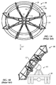
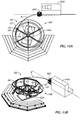
- Fig. 1A reproduces a conventional transport reel 10 used for storing and transporting coiled rod.
- the reel 10 has a hub 12 with arms 14 extending outward therefrom. Bars 16/18 connected to each of the arms 14 extend upwards, and wire rings 22/24/26/28 interconnect the bars 16/18 together.
- a length of continuous rod (not shown) can be coiled in (and uncoiled from) the bars 16/18 as the reel 10 is rotated about the hub 12.
- This conventional reel 10 has a diameter of 5.5 m (18-ft), which is the standard throughout the industry.
- the elliptical rod was used for a long time exclusively in North America and mainly in Canada. Accordingly, manufacturers configured a reel with a 5.5 m (18-ft; 216-in) diameter based on Canada's transport regulations to store and transport rod. This 5.5 m(18-ft) diameter reel, such as disclosed in U.S. Pat. No. 3,504,866 , was large enough for coiling the rod on the reel 10 without permanent deformation, but was small enough to facilitate transporting the reel 10 under Canada's regulations.
- Fig. 1B shows an end view of a truck trailer 30 carrying a conventional 5.5 m (18-ft) diameter reel 10 on a support 40.
- the trailer 30 can have one or more such reels 10 disposed along its length and can be hauled by a truck, a dedicated vehicle, etc.
- the reels 10 carry the continuous rod, and the trailer 30 transports the reels 10 from a manufacturing facility to a well site for installation or to a ship for international or overseas shipment.
- the traveling space for the trailer 30 and reels 10 viewed from the end is limited to about 3.7 m (12-ft) by 4.6 m (15-ft). In this way, the reels 10 with their 5.5 m (18-ft) diameter are built as large as possible to just meet the dimensional limits defined by Canada's transport regulations so they can be transported with less restriction.
- the conventional reel 10 shipped with the coiled rod is a substantial inventory item. Therefore, the empty reel 10 must be returned to a facility for reuse. As expected, returning the empty reel 10 from a distant location to the manufacturing facility can still cost a considerable amount.
- US 3,504,866 describes an apparatus for the transportation of a coil such as a coiled, continuous sucker rod string.
- a ring-like open-topped storage channel is rotatably mounted on a carrier, such a truck bed, in a tilted position.
- Rod string may be fed into the moving channel and its outer upstanding side wall will form the string into an elastically deformed, coiled condition for transportation.
- US 5,215,272 describes a method and apparatus for pulling cables having a subassembly including a cooperatively driven line pulling take-up spool and level winding device.
- FR 2,707,221 describes a vehicle for transporting at least one reel for packaging and storing an elongate flexible element.
- the transport vehicle includes an axle assembly equipped with means for supporting a reel including two lateral cheeks arranged on either side of a central drum equipped with an axial bore.
- the transport vehicle further includes handling means designed to move the reel from a storage position into a transport position.
- FR 2,342,865 describes an articulated console activated by an actuator manipulated by a road crew, which enables the transport of items that are relatively light but very wide.
- US 4,767,073 describes a stationary or mobile cable spooling system for winding up electrical cables used on drilling rigs comprised of an axle for insertion into a cable spool, a yoke for rotationally mounting the axle, a hydraulic motor coupled to the axle for rotating the spool and a cable guide system which evenly winds the cable onto the spool.
- US 3,655,218 describes an articulated flat bed trailer for transporting large, bulky objects such as ships propellers and the like.
- the flat bed of the trailer includes a hinged portion hydraulically rotatable from the horizontal position to an angle of approximately 55 degrees to 35 degrees from the horizontal to minimize simultaneously horizontal and vertical overhang of the object.
- Means are provided to maintain the center of gravity of the rotated flat bed portion.
- AU 2008/100744 describes a transportable pumping apparatus.
- US 6,347,761 describes a mobile cable dispensing system for dispensing and retrieving cable from a spool of cable.
- WO 2010/019047 describes a reel assembly for supplying a continuous composite tubing of a type used in oilfield operations, which reel assembly comprises a stand onto which a spool of continuous composite tubing is lowered and a drive coupling for transmitting rotational force from the stand to the spool. A removable cage is connected with the stand. The continuous composite tubing is arranged around the outer periphery of the spool, in a U-formed housing.
- US 5,404,757 describes a device for driving rods used primarily for soil mechanics tests into the ground, of the type comprising a traction and compression resistant tubular one-piece rod made of a material and capable of being curved by reversible elastic derformation, a drum for winding said rod and a device for driving and extracting said rod.
- EP 0266206 describes a method and apparatus for driving one piece ground rods into the earth.
- a coiled supply of rod is fed from coiled supply downwardly through a driver which includes two sets of straightener rolls, and into a vertically movable gripping jaw.
- the jaw is mounted on a slide movable axially of the rod.
- the subject matter of the present disclosure is directed to overcoming, or at least reducing the effects of, one or more of the problems set forth above.
- the platform may rotatably support the reel thereon.
- the system may further comprise a motor disposed on the platform and coupled to a wheel to which the reel is rotatably supported, the motor controlling rotation of the reel.
- the system may further comprise a piston coupled between the base and the platform and pivoting the platform relative to the base.
- the platform may comprise arms extending therefrom and having ends enclosing around an edge of the reel.
- the ends may be movable on the arms relative to the edge.
- the ends may comprise wheels rotatably disposed thereon, the wheels having blades engaging portion of the reel and rotating with the reel by the engagement.
- the system may further comprise a trailer supporting the pedestal.
- the trailer may comprise a hydraulic system and a power unit providing power to the hydraulic system.
- the trailer may comprise a deployment unit disposed thereon for moving the continuous rod relative to the reel.
- the deployment unit may comprise a rod transfer unit and a rod bender unit communicating the rod between each other, the rod transfer unit moving the rod relative to the reel, the rod bender unit bending the rod being moved.
- the system may further comprise a guide tube positioned adjacent the reel and connected to the deployment unit and guiding the continuous rod therebetween.
- the deployment unit may comprise a frame removably mountable on the trailer.
- At least a portion of the deployment unit may be mounted on the trailer and pivots relative to the trailer.
- the system may further comprise a gate disposed on the reel and selectively opening and closing over a passage in the reel for the continuous rod coiled therein.
- the gate may comprise a first bar rotatably coupled to a second bar, wherein the first bar selectively opens and closes over the passage when rotated by the second bar.
- the pedestal may comprise: a first location engaging the second bar when the reel rotates relative thereto and opening the first bar over the passage; and a second location engaging the second bar when the reel rotates relative thereto and closing the first bar over the passage.
- a trailer transport stand for a reel of continuous rod comprises: a base disposing on a bed of the trailer; a platform pivotably connected to the base and supporting the reel for the continuous rod thereon; at least one support removably disposing between the platform and the base and holding the platform at an angle relative to the base; and a plurality of arms connected to the platform and pivotable inward to the platform around an edge of the reel.
- the platform may collapse against the base, and the arms may pivot outward from the platform.
- Ends of the arms may affix to one another across the reel supported on the platform.
- the platform may comprises a mount to which a hub of the reel affixes.
- a transport trailer for a reel of continuous rod comprises: a body supported by wheels; a pedestal supported on the body and rotatably supporting the reel for the continuous rod thereon; a deployment unit disposed on the body, the deployment unit bending and moving the rod relative to the reel.
- the deployment unit may comprise a rod transfer unit and a rod bender unit communicating the rod between each other, the rod transfer unit moving the rod relative to the reel, the rod bender unit bending the rod being moved.
- the deployment unit may comprise a guide tube positioning from adjacent the reel to the deployment unit and guiding the moving rod therebetween.
- the deployment unit may comprise a frame removably mountable on the body of the trailer.
- the frame may hold a rod bender unit adjacent a rod transfer unit and may store a guide tube thereon.
- At least a portion of the deployment unit may mount on the trailer and move relative to the reel.
- the deployment unit may comprise a rod bender unit disposed on an arm, the arm pivotably affixed to the body of the trailer and pivoting the rod bender unit relative to the reel.
- the deployment unit may comprise a rod transfer unit disposed on a platform, the platform slidably affixed to the body of the trailer and sliding the rod transfer unit relative to the reel.
- a method of unwinding continuous rod from a transport reel to a destination comprises: uncoiling the continuous rod from the transport reel; permanently straightening the uncoiled rod relative to its axial length; and conveying the straightened rod to the destination.
- a continuous rod transport system uses a pedestal having a base and a platform.
- This pedestal can be a transport stand for a bed of a trailer or can be a mount disposed on the frame of a dedicated trailer.
- the platform articulates relative to the base and supports a reel for continuous rod thereon.
- the pedestal's platform When used on a dedicated trailer, the pedestal's platform rotatably supports the reel thereon and has a motor coupled to a wheel to which the reel is rotatably supported. During operation, the motor controls the rotation of the reel.
- a piston coupled between the base and the platform can pivot the platform relative to the base about a pivot to prepare the reel for winding or unwinding rod from the reel.
- arms extend outward and have ends enclosing around an edge of the reel. These ends can have wheels rotatably disposed thereon.
- the wheels have blades engaging portion of the reel and rotating with the reel by the engagement. These blades can close off a passage in the reel for the rod into or out of the reel.
- gates disposed on the reel can selectively open and close over the passage in the reel for the continuous rod coiled therein.
- Interconnected bars rotate together. When one bar reaches a first point in the reel's rotation, it opens the connected bar to open up the passage. Then, when the bar reaches a second point in the reel's rotation, it closes the connected bar to close off the passage.
- the reel for the continuous rod has a cage with a support disposed about a center of the cage.
- the support holds the continuous rod coiled about the center of the cage.
- the cage can have a fixed hub or a removable hub for rotating the cage.
- the removable hub positions in the center of the cage and can removably attach to the cage.
- the reel can have any suitable diameter and can have a reduced diameter at least less than 5.5 m (18-ft) and approximately 4.3 m (14-ft) or even less.
- a trailer transport stand transports a reel of continuous rod on a bed of the trailer.
- the stand has a base that disposes on the bed.
- a platform pivotably connects to the base and supports the reel for the continuous rod thereon.
- At least one support removably disposes between the platform and the base and holds the platform at an angle relative to the base when transporting the reel with the stand.
- arms connected to the platform can pivot inward to the platform around an outer edge of the reel. Ends of these arms affix to one another with chains across the reel to support the reel on the platform.
- the stand When not holding a reel, the stand can collapse to a flat condition for return transport. In this condition, the platform collapses against the base, and the arms pivot outward from the platform.
- a transport trailer for a reel of continuous rod has a body supported by wheels.
- a pedestal supported on the body rotatably supports the reel for the continuous rod thereon.
- a deployment unit disposed on the body can both bend and move the rod relative to the reel.
- the deployment unit can have a rod transfer unit and a rod bender unit that communicate the rod between each other. The rod transfer unit moves the rod relative to the reel, and the rod bender unit bends the rod being moved.
- a guide tube can connect from adjacent the reel to the deployment unit and can guide the moving rod therebetween.
- the deployment unit can have a frame for the bender and transfer units.
- This frame can removably mount on the body of the trailer so it can be set up for operation.
- the rod bender unit can pivot on an arm affixed to the body of the trailer to pivot relative to the reel.
- the rod transfer unit can slide on a platform affixed to the body of the trailer to slide relative to the bender unit.
- the transfer unit and the rod bender may be connected to each other such that they may be deployed together by a single action. Deployment of the transfer unit and the rod bender can be achieved manually or automatically (i.e., using a hydraulic actuator or the like).
- the continuous rod is conveyed along its axial length from a source and is permanently bent at an angle relative to its axial length. Once bent, the bent rod is coiled a number of times in the transport reel.
- manufactured rod is first curved before being loaded into the reel at least at the start of winding the rod in the reel. Eventually, the rod may not need to be bent before being coiled in the reel.
- the continuous rod is uncoiled from the transport reel and is permanently straightened relative to its axial length.
- the straightened rod is then conveyed to the handling unit, such as a gripper system at a wellsite.
- the transport reels disclosed herein can be transported using commonly available transport units, such as flat deck trailers and flat deck railcars. All the same, the system can reduce transportation costs.
- the disclosed transport system has a number of independent modules (i.e., units, reels, stands, etc). These modules can be manufactured independently and at different locations along a transport chain. Thus, certain modules can built within one regulatory area where the complete unit is intend to be deployed, while other modules can be built in other locations. In this way, the modules can be built based on local variations to meet specific local requirements for transporting coiled rod in transport reels using road, trailer, railcar, ship, etc.
- a first transport reel 50A for continuous rod (not shown) has a cage 100 and a removable hub 200 that are separate components coupleable together to form the complete reel 50A.
- the cage 100 has a support 102 disposed about a center 104 of the cage 100 for holding the continuous rod coiled in the cage 100.
- several separate support members 110 are used for the support 102 to hold the coiled rod therein.
- the cage's support 102 has eight such support members 110, although more or less support members 110 could be used.
- These support members 110 are disposed about the cage's center 104 and are interconnected together by several rings 160 as discussed in more detail later.
- the support 102 can be a continuous wall disposed about the periphery of the cage 100 for holding the coiled rod therein.
- the hub 200 has arms 220 disposed about a central member 210. Each of the arms 220 has a distal end 230 with a lock 240. As best shown in Fig. 2B , the arm's distal ends 230-of which there are also eight-couple to the support members 110 of the cage to form the complete reel 50A.
- each support member 110 is disposed about a center of the cage 100 for holding the coiled rod.
- Each support member 110 has an outer upright 120 toward the cage's outer perimeter and has an inner upright 130 toward the cage's inner perimeter.
- the outer upright 120 define an acute angle 122 and holds the spring bias of the rod when coiled in the cage 100. This angle 122 helps to layer the continuous rod at it is coiled inside the cage 100.
- Each of the inner uprights 130 has a foot 140 at one end (connected to the outer upright 120) and has a head 150 at a free end (separated from the outer upright 120).
- Rings 160 disposed about the cage 100 attach to the uprights 120/130 and interconnect the support members 110 together.
- one ring 162 attaches inside the outer upright's angles 122
- another ring 164 attaches inside the outer uprights 120 where they connect to the inner uprights 130.
- the cage 100 also has two rings 166/168 disposed about the free ends of the uprights 120/130. These two rings 166/168 define a circumferential slot 165 for passage of the continuous rod into and out of the cage 100 during use.
- the support members 110 can be composed of square, round, flat, or other shaped bars or rods that can be integrally formed or can be welded, bolted, or otherwise affixed together. Separate support members 110 tied together by interconnecting rings 160 is preferred to reduce the weight and cost of the cage 100, which may be reusable or may be an expendable component. However, the support 102 can use walls or other flat surface disposed about the outer perimeter of the cage 100 to hold the continuous rod if desired.
- the hub 200 has arms 220 that extend from the hub's central member 210 and that removably couple to the cage 100. As best shown in Fig. 2B , the hub 200 positions in the center of the cage 100, and the locks 240 on the arms' distal ends 230 attach to the feet 140 on the cage's inner uprights 130. Further details of this coupling are provided later.
- the hub's central member 210 can fit onto an axle or axis of handling equipment, and the reel 50A having the cage 100 and hub 200 can be rotated thereabout when coiling and uncoiling the rod. Therefore, the hub 200 can be used for handling the cage 100 in a manufacturing facility and at a work site, but can be removed for transporting the cage 100 by itself.
- the cage 100 can not only couple to the hub 200 as shown in Fig. 2B , but separate cages 100A-B as shown in Fig. 3 can stack on top of one another.
- each of the inner uprights 130 has a head 150 at one end and has a foot 140 on the opposite end.
- the feet 140 on the upper cage 100A fit onto the heads 150 on the lower cage 100B.
- two or more cages 100 can be stacked together as shown. Stacking of the cages 100A-B in this way can facilitate the storage and handling of the cages 100A-B whether they have continuous rod coiled therein or not. This stacking also allows the cages 100 to be easily stored as inventory at a facility.
- Figs. 4 through 6 provide further details directed to the coupling between the cage 100 and the removable hub 200.
- Fig. 4 shows a foot 140 on the cage's inner upright 130.
- the lower end of the upright 130 has a slot 132 surrounded by a skirt 142 on three outer sides.
- the inner side of the upright 130 facing toward the cage's center has a shoulder 148.
- the upper face of this shoulder 148 is perpendicular to the upright 130, while the lower face is slanted.
- Fig. 5 shows a distal end 230 of the hub's arm 200.
- a lower bar 222 of the arm 220 connected to the hub's central member (210) extends to the arm's distal end 230, while an upper bar 224 of the arm 220 connects from the central member (210) to the lower bar 222 just short of the distal end 230.
- a nub 232 extends upward from the lower bar 224, and a pivot base 234 extends downward from the lower bar 222.
- the lock 240 on the arm 220 has parallel levers 242 on one side of the bar 224 and has an opposing lever 244 on the other side. These levers 242/244 pivot on a pin 246 disposed in the bar's pivot base 234. An upper pin 248 connects the distal ends of the levers 242/244 together, and an intermediate pin 243 is disposed between the parallel levers 242.
- An actuator 250 pivotably extends from a shelf 223 on the lower bar 222 to the lock 240.
- the actuator 250 includes a cylinder 252 with a piston rod 254 extending therefrom and biased by a spring 256. Although shown unattached in Fig. 5 , the distal end of the piston rod 254 couples to the intermediate pin 243 on the levers 242 to pivot the lock 240 about the pivot pin 246.
- the actuator 250 is a pneumatic piston operated by a separate air supply (not shown) that can be connected to the actuator 250 to activate it.
- Fig. 6 shows how the cage's foot 140 couples to the hub's arm 220.
- the foot 140 on the cage's inner upright 130 aligns with the nub 232 on the arm's distal end 230.
- the cage (100) and hub (200) are brought together, and the nub 232 inserts into the upright's slot 132.
- the skirt 142 helps align the nub 232 with the upright 130 and also helps to hold the foot 140 on the distal end 230 of the arm 220.
- the lock 240 With its levers is pivoted upward from the bias of the spring 256. However, the slanted face of the shoulder 148 pushes the lock 240 when it hits the locking pin 248 as the cage (100) and hub (200) are brought together. When the foot 140 seats on the nub 232, the lock 240 is biased back to its upright position so that the locking pin 248 engages the perpendicular face of the shoulder 148. This coupling is done for each of the hub's arms 220 to each of the cage's feet 140 to connect the hub (200) and cage (100).
- the location of the pivot 246 offset from the alignment between the foot 140 and nub 232 tends to force the lever arms 242/244 further onto the shoulder 148 if the cage (100) and the hub (200) move to separate from one another.
- the lock 240 is held on the shoulder 148 by the spring 256.
- the location of the pivot 246 with regards to the shoulder 148 on the upright 130 helps to draw the locking pin 248 into the inner upright 130 if the cage 100 is drawn off the hub 200. This helps ensure the engagement of the locking pin 248 on the shoulder 148 without the need for the application of force by the spring 256.
- the lock 240 is pulled back from the shoulder 148 to release the cage's foot 140 to the hub's arm 220. This can be done manually using a tool or the like. Alternatively, as shown in Fig. 6 , the pneumatic piston 250 can be activated to pull back the lock 240 from the shoulder 148 to release the foot 140 from the arm 220. Either way, each of the hub's arms 220 is uncoupled from each of the cage's feet 140 to release the hub (200) and cage (100).
- Figs. 7A through 8B provide further details of another lock for coupling the cage 100 and the removable hub 200 together.
- the distal end 230 of the hub's arm 200 has the nub 232 extending from the lower bar 222 as before.
- a pivot base 236 attached to the side of the bar 222 has a lever arm 245 pivotably disposed therein.
- One end of this lever arm 245 connects by a coupling 255 to the actuator 250 having the cylinder 252, piston 254, and spring 256.
- this actuator 250 is affixed to a shelf 223 attached on the bar 222.
- the foot 140 on the cage's inner upright 130 has the slot 132 surrounded by the skirt 142 as before.
- the inner side of the upright 130 has a shoulder 148, although it may be less wide than before.
- the nub 232 inserts into the upright's slot 132 when brought together.
- the slanted face of the shoulder 148 pushes the lever arm 245 so that it turns in the pivot base 236.
- the lever arm 245 is biased back by the spring 256 to catch on the shoulder 148.
- the upper face of this shoulder 148 can be slanted inward to further catch with the lever arm 245 if desired.
- the lever arm 245 is held on the shoulder 148 by the spring 256, and the slant of the shoulder 148 can further pull the lever arm 245 toward the upright 130 if the cage (100) is drawn off the hub (200).
- the lever arm 245 is pulled back from the shoulder 148 manually using a tool or the like or using the actuator 250.
- the pneumatic cylinder 252 can be activated to pull back the lever arm 245 from the shoulder 148 to release the foot 140 from the arm 220.
- locks Although two locks have been disclosed for coupling the cage 100 to the removable hub 200, other forms of locks can be used. In general, the locks can use levers, latches, bolts, shoulders, ties, or other fasteners or mechanisms that removably interconnect portion of the cage 100 to portion of the hub 200.
- a second transport reel 50B for continuous rod (not shown) has a cage 300 and a removable hub 400 that are separate components coupleable together to form the complete reel 50B.
- the cage 300 has a support 302 disposed about a center 304 of the cage 300 for holding the continuous rod coiled in the cage 300.
- the support 302 has eight support members 310, although more or less could be used.
- the cage's support 302 could be in the form of a continuous wall or the like disposed about the periphery of the cage for holding the coiled rod therein.
- the hub 400 has arms 420 disposed about a central member 410.
- Each of the arms 420 has a distal end 430.
- the arm's distal ends 430-of which there are also eight-couple to the support members 310 of the cage 300 to form the complete reel 50B.
- one or more of the arm's distal ends 430 can have a lock (labeled 440), such as described in more detail later.
- the support members 310 are disposed about the center 304 of the cage 300 for holding the coiled rod. Some of the support members (i.e., such as those labeled 311) are smaller than the main support members 310. Each support member 310 has an outer upright 320 toward the cage's outer perimeter to hold the spring bias of the rod when coiled in the cage 300.
- Each outer upright 320 has upper and lower legs 322/324 extending from the ends of the uprights 320 toward the center of the cage 300. Preferably, these legs 322/324 are slightly angled from perpendicular to the upright 320, which facilitates stacking the cages 300 as described below. Rings 360 disposed about the cage 300 attach around the ends of the uprights 320 and interconnect the support members 310 together. In addition, upper and lower rings 362/364 attach around the upper and lower legs 322/324 to interconnect the support members 310 together.
- the uprights 320 on the main support members 310 each have a foot 340 at one end and have a head 350 at the other end.
- the lower legs 324 on the main support members 310 each have a guide 325.
- the feet 340, heads 350, and guides 325 are discussed in more detail later.
- this cage 300 defines a diameter less than 5.5 m (18-ft). Yet, this cage 300 preferably defines a diameter less than 4.3 m (14-ft) and more preferably about 3.7 m (12-ft) or 3.5 m (11.5-ft).
- the outer uprights 320 of this cage 300 do not define an angle so the outer periphery of the cage 300 is cylindrical. Lacking an angle to guide the rod naturally into layers into the cage 300, coiling rod into this cage 300 may require equipment to feed the rod into the cage 300 so that it layers neatly inside. To facilitate proper layering, this equipment may also load the rod into the cage 300 while the cage 30 is upright.
- the hub 400 has arms 420 that extend from the central member 410 and that removably couple to the cage 300. As best shown in Fig. 9B , the hub 400 positions in the center of the cage 300, and locks (labeled at 440) on the arms' distal ends 430 attach to the cage's support members 310. Further details of one type of lock 440 for this coupling are provided later.
- the hub's arms 420 have lower and upper bars 422/424 that extend from the central member 410 to the arm's distal ends 430.
- Inner uprights 426 extend from the upper bars 424 and have a ring 428 interconnecting the upright's ends together.
- the hub's ring 428 defines a circumferential slot with the cage's upper ring 362 so continuous rod can be passed into and out of the cage 300 during use.
- the hub's central member 410 can fit onto an axle or axis of handling equipment, and the reel 50B having the cage 300 and hub 400 can be rotated thereabout when coiling and uncoiling the rod. Therefore, the hub 400 can be used for handling the cage 300 in a manufacturing facility and at a work site, but can be removed for transporting the cage 300 by itself.
- the cage 300 can not only couple to the hub 400 as shown in Fig. 9B , but separate cages 300A-B as shown in Fig. 10 can stack together.
- each of the support members 310 has an upper leg 322 and a lower leg 324.
- the guides 325 on the lower legs 324 of the upper cage 300A fit onto the upper legs 322 of the lower cage 300B.
- the heads 350 if present on the lower cage 300B, can insert in the feet 340 on the upper cage 300A as described later.
- two or more cages 300 can be stacked together as shown. Stacking of the cages 300A-B in this way can facilitate storage and handling of the cages 300A-B whether they have continuous rod coiled therein or not. This stacking also allows the cages 300 to be easily stored as inventory at a facility.
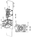
- Figs. 11A-11B show one type of lock 440 for coupling the cage (300) and hub (400) together.
- an upper bar 424 of the hub's arm 420 connected to the central member (410) extends to the arm's distal end 430, while a lower bar 422 of the arm 420 connects from the central member (410) to the upper bar 424 just short of the distal end 430.
- a nub 432 extends upward from the end of the upper bar 422. This nub 432 positions in the foot 340 of the cage's upright 310 when disposed thereon, as the guide 325 on the support's lower leg 324 positions against the upper bar 424.
- the angled lower leg 324 and the guides 325 on the cage (300) along with the angled bar 422 on the hub (400) help to locate and self-center the cage (300) and hub (400) together. Therefore, the arm 420 may not have (or require) the nub 432.
- this lock 440 has a lever 442 pivotably connected to the upper bar 424.
- the lever 442 moves a cross pin 448 relative to a shoulder 348 on the support's leg 324, and an actuator 450 pivotably extends from the upper bar 424 to the lever 442.
- this actuator 450 can have a cylinder 452 with a piston rod 454 biased by a spring 456.
- the nub 432 if present, can insert into the upright's foot 340.
- the lever 442 is pivoted outward by the bias of the spring 456.
- the slanted face of the shoulder 348 pushes the lever 442 when it hits the cross pin 448 as the cage (300) and hub (400) are brought together.
- the lever 442 is biased back to its upright position so that the cross pin 448 engages the perpendicular face of the shoulder 348.
- the offset location of the pivot 446 tends to force the lever 442 further onto the shoulder 348 if the cage (300) and the hub (400) move to separate from one another.
- the actuator 450 pulls back the lever 442 from the shoulder 348.
- a rod or pin 449 disposed on the upper arm 424 can be biased by spring 456 to insert into an open end of the lower leg 324 when the leg 324 is brought next to the arm 424.
- the biased pin 449 can then be pulled out of the end of the lower leg 324 by an actuator 450.
- Fig. 12 seating one cage 300A on another 300B when stacking them together is shown in more detail.
- the guide 325 on the leg 324 of the upper cage's upright 310A fits onto the leg 322 of the lower cage's upright 310B.
- the upright 310A is shown having its foot 340 positioned on the head 350 of the other upright 310B, the heads 350 may not be needed.
- the angled lower leg 324 and guides 325 on the upper cage 300A along with the angled leg 322 on the lower cage 300B help to locate and self-center the cages 300A-B when stacked together. These and other forms of coupling could be used when stacking cages together.
- the cages 100/300 have reduced size compared to conventional reels used in the art.
- the conventional reel for storing and transporting coiled rod-even round rod- has an 5.5 m (18-ft) diameter that has become the industry standard.
- the 5.5 m (18-ft) diameter reel was initially suited for elliptical cross-section rod and Canada's transport regulations.
- round rod developed later for rotary pump applications also used the existing 5.5 m (18-ft) diameter reels, and the yielding produced in the round rod when coiled on these 5.5 m (18-ft) reels simply became accepted. Therefore, the round rod has been used with the conventional 5.5 m (18-ft) diameter reels for many years.
- the cages 100/300 of the disclosed reels 50A-B have diameters less than 5.5 m (18-ft, (216-in).
- the cage 100 of Figs. 2A-2B has a diameter of approximately 4.3 m (14-ft, 168-in)
- the cage 300 of Figs. 9A-9B has a diameter of approximately 3.7 m (12-ft, 144-in) or 3.5 m (11.5-ft, 137-in).
- the plastic strain resulting from coiling round rod on a conventional 5.5 m (18-ft) diameter reel is about 0.5%, which has not caused performance problems so that the use of the 5.5 m (18-ft) diameter reel for round rod has become accepted practice.
- Coiling round rod on as small as a 3.7 m (12-ft) diameter would increase the plastic strain to about 0.7%.
- the increase in the strain is small (i.e., 0.2%)
- the cold work from coiling the rod on a smaller spooling diameter would be expected to adversely affect various properties of the round rod, which would be detrimental to the rod's performance. These affected properties relate to mechanical property changes, localized corrosion resistance, environmental cracking resistance, and high cycle fatigue.
- SSC sulfide stress cracking
- test specimens Four-point bent beam specimens were machined from each of the test samples, and the test specimens were strain gauged in different H 2 S environments. The purpose of the tests was to determine whether there would be a difference in performance between the coiling diameters in an environment that more closely approximated a typical oil environment. None of the test specimens failed during the tests in the different H 2 S environment. In fact, no environmental cracking was detected so the rod was found to exhibit good resistance to sulfide stress cracking regardless of bending diameter (as low as 3.7 m (12-ft)).
- the most common failure mode for continuous rod is high cycle fatigue. Accordingly, high cycle fatigue tests were performed to assess changes in the fatigue resistance with respect to the spooling diameter as low as 3.7 m (12-ft).
- the fatigue tests were conducted using the standard 0.1 "R" ratio and high cycle fatigue specimens that are appropriate to the rod's geometry. As is known, the "R" ratio is the ratio of the minimum load to the maximum load.
- the specimens were curved such that the gage section that was fatigue-tested was near the OD of the rod along the plane of highest bending (outer radius). The samples tested were from the standard 5.5 m (18-ft) spooling diameter and the smaller 3.7 m (12-ft) spooling diameter.
- the tests investigated tensile properties, localized corrosion resistance, environmental cracking resistance, and high cycle fatigue life of the rod having 3.7 m (12-ft) and 5.5 m (18-ft) spooling diameters. In all measured properties, there were no significant differences between rod samples subjected to the two spooling diameters.
- the spooling diameter of the disclosed cages 100/300 can be less than 5.5 m (18-ft) without adversely affecting the properties and performance expected from the continuous rod.
- the spooling diameter of the disclosed cage 300 in Figs. 9A-9B can be as small as 3.7 m (12-ft) based on the testing.
- a 4 m (13-ft) spooling diameter has been chosen for the disclosed cage 100 of Figs. 2A-2B and a 3.7 m (12-ft, or 11.5-ft) spooling diameter has been chosen for the disclosed cage 300 of Figs. 9A-9B .
- these diameters just meet the size and space limitations conducive to transporting the cage.
- the cages 100/300 can hold the spring bias of the continuous rod once coiled therein. Because the hub 200/400 is removable, operators can transport coiled rod in the cage 100/300 alone without the removable hub 200/400. This reduces the total weight of what must be shipped to transport the coiled rod and greatly reduces the transportation costs.
- the modular nature of the reels 50A-B can also reduce transportation cost because some components used to transport the coiled rod may be specifically expendable while other may be reusable.
- the cages 100/300 may be an expendable transport component or could be reusable depending on transportation costs and where the rod is being shipped.
- the cages 100/300 can be lost packaging for long distance transport, but the cages 100/300 can be reused if returned to the manufacturing facility when economically feasible.
- the removable hubs 200/400 can be shipped separately from worksite to worksite and do not need to be shipped and returned with the cages 100/300.
- the cages 100/300 are also more amenable to forms of transportation not available for conventional 5.5 m (18-ft) reels used in the industry.
- the smaller diameter cages 100/300 can be transported by rail and can require less space on a truck trailer.
- the smaller diameter cages 100/300 can fit inside a shipping container typically used for rail and oversea transport.
- This container is commonly referred to as a super rack container.
- the super rack container is available from Super Rack Global Pte Ltd. and disclosed in U.S. Pat. No. 6,227,397 .
- the super rack container is open an all sides, although it may have fixed or collapsible end walls. Unlike the conventional flat rack, the super rack container has telescoping corner posts that can extend to different levels.
- One available super rack container is the 40' Highcube Super Rack available from Super Rack that has interior dimensions of 11.615 m (457.3-in) () (L) x 2.438-m (96-in) (W) x a height (H) ranging in 4 increments from 2.264-m (89-in) to 3.483-m (137-in).
- These types of super rack containers can be used by shipping services and carriers, such as the United Arab Shipping Company (UASC), Hanjin Shipping, Sarjak, HMM, STX Pan Ocean, etc.
- the cages 100/300 can be transported by the intermodal transport system in an intermodal container by rail, ship, and truck.
- This form of transport does not require the cages 100/300 to be handled directly when changing from one mode of transport to another. Therefore, standard cranes and other handling equipment of the intermodal transport system can be used when transporting the cages 100/300 in the containers.
- Empty cages 100/300, if to be returned to a manufacturing facility, are preferably transported in the containers so they can be handled using the existing intermodal container system even when returned.
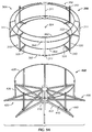
- Figs. 13A-13B show side and end views of a super rack container 500 having two cages 100A-B of the first transport reel 50A. As noted previously, these cages 100A-B define a diameter of about 4.3 m (14-ft).
- the super rack container 500 has a platform 502, end walls 504, and extendable corner posts 506. The sides of the container 500 can be open to facilitate loading.
- the container 500 can be carried on a rail car or on a ship and can have the standard outer dimensions of about 12.19 m (480-in) (length) x 243.8 cm (96-in) (width) x 411.5 cm (162-in) (height) or similar thereto.
- the interior dimensions of the container 500 may be 11.63 m (458-in) (L) x 243.8 cm (96-in) (W) x 348 cm (137-in) (H).
- the platform 502 and posts 506 allow several such containers 500 to be stacked one on top of another when carried on a ship.
- Stands 510A-B hold the cages 100A-B in the container 500.
- Each stand 510A-B sits on the platform 502 and has an angled wall 512 extending therefrom, which can be at an angle ⁇ of about 60-degrees.
- the angled wall 512 supports the cage 100 thereon in a space defining a height (h) less than or equal to 348 cm (137-in) ( i.e., about 345.4 cm (136-in)) and defining a depth (d) less than or equal to 243.8 cm (96-in (i.e., about 93-in)).
- the cage 100 may encompass a space having 247.5 cm (92 7/16-in) (d) x 345.3 cm (135 15/16-in) (h) x 426.7 cm (168-in) (w).
- the cages 100A-B can be transported without the hubs 200 disposed thereon, and ledges or shelves 514 may support the lower end of the cages 100A-B.
- ties, bolts, or other form of fastening can be used to affix the cages 100A-B to the walls 512 and/or platform 502 depending on the transportation needs.
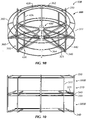
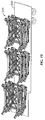
- Figs. 14A-14C illustrate perspective, side, and end views of a super rack container 500 having multiple cages 300 of the second transport reel disclosed herein.
- these cages 300 define a diameter (d) of about 3.48 m (11-ft 5-in (137-in), although the cage 300 may measure a diameter of about 356 cm (140-in) from one outer upright to the other. With the diameter of 348 cm (137-in), six such cages 300 stand upright in the dimensions of the super rack container 500. In particular, the cages 300 stand in pairs side-by-side along the length of the container 500.
- the two cages 300 side-by-side define a width of about 229 cm (90 3/16-in), which is less than the internal width (W) of 243.8 cm (96-in) for the container 500.
- the height of the standing cage 300 is about 348 cm (137-in), which is at the internal height (H) of 348 cm (137-in) for the container 500.
- These cages 300 can be supported by triangular supports between the pairs and by chains and other conventional means for supporting cargo. Although shown without the hubs 400, transporting the cages 300 with the hubs 400 with the super rack containers 500 could also maintain reduced shipping costs. As such, the benefits of the smaller diameter cage 300 could be maintained even though the hub 400 is not removed or is not even removable.
- the cost of transporting the continuous rod is expected to be significantly reduced below the current industry standard, and in some instances, the cost may be reduced by as much as fifty percent.
- the conventional shipping method uses the conventional 5.5 m (18-ft) diameter reels that must be transported by truck on land. For overseas shipments, the conventional reels are break bulk and are stored below deck.
- a new shipping method can use super rack containers (500) that can be transported by rail and stored above deck on a ship.
- example cost for shipping two reels by the conventional method from Canada to Houston and then Houston to the Middle East may be about $12,500.00 per reel.
- Table 1 Example Transportation Costs by Conventional Method Description Total Cost Reels Cost/Reel Canada to Houston $10,000.00 2 $5,000.00 Houston to Middle East $15,000.00 2 $7,500.00 Summary $25,000.00 2 $12,500.00
- example cost for shipping continuous rod by the new method from Canada to the Middle East may be about $6,250.00 per cage.
- This new method uses the cages (100) having the 4.3 m (14-ft) diameter shipped with coiled rod without the removable hub (200). These cages (100) can be positioned on stands (510) and fit onto super rack containers (500), which can be carried like standard freight on rail lines, vessels, and the like. Using this new method, the shipping cost per cage is about 50% less expensive compared to the conventional method currently in use.
- Table 2 Example Transportation Costs by New Method Description Total Cost Cage Cost/Cage Canada to Middle East $12,500.00 2 $6,250.00
- Each cage (100), however, for the new transportation method has about 20% less coiled rod compared to the conventional 5.5 m (18-ft) diameter reels. Therefore, more cages (100) need to be shipped in order to transport the same amount of coiled rod. As shown in the cost analysis of Table 5 below, transporting forty conventional reels of coiled rod at $12,500 per reel may cost a total of $500,000 using the conventional method. Using the new method, forty-eight cages (100) must be used to transport the same length of rod. As can be seen by the difference in cost, however, even though more cages must be shipped, the new method still results in a total cost that is about 40% less than the conventional method. Table 3: Cost Analysis Description Cost/Reel No. of Reels Total Cost Conventional Method $12,500.00 40 $500,000.00 New Method $6,250.00 48 $300,000.00 Savings $200,000.00
- the disclosed reel 50 having the 4.3m (14-ft) diameter cage 100 and removable hub 200 represents a significant improvement over current industry practices for transporting continuous rod. Moreover, due to the long-standing use of the conventional 4.3 m, (18-ft) diameter reels and the reluctance to use any other transport method, the disclosed reel 50 having the 4.3 m (14-ft) diameter cage 100 and removable hub 200 satisfies a long felt need in the industry to deal with the existing limits of transporting continuous rod. The use of the smaller diameter cages 300 of Figs. 9A-9B in the super rack containers 500 is expected to reduce transportation costs as well.
- Figures 15A-15B show an assembly for winding a transport reel 50C with rod R.
- the transport reel 50C has a fixed cage and frame arrangement as opposed to the modular arrangement disclosed previously.
- the procedures for winding the modular reels discussed previously can be the same.
- the transport reel 50C can have a diameter less than the typical diameter of 5.5 m (18-ft).
- the reel 50C can have a diameter of about 4.3 m (14-ft, 196-in), 4 m (13-ft, 156-in), or even less.
- the height of the reel 50C can be about 106.7 cm (42-in).
- the reel 50C has a hub 62 with arms 64 extending outward therefrom to support a cage 60.
- the cage 60 has bars 66/68 that connect to each of the arms 64 and that extend upwards therefrom.
- Wire rings 67 of the cage 60 interconnect the bars 66/68 together.
- Top rings 67 define a circumferential slot 65 around the top of the cage 60.
- a length of continuous rod R can be coiled in (and uncoiled from) the cage 60 through this slot 65 as the reel 50C is rotated about the hub 62.
- the hub 62 and arms 64 can be fixedly connected to the bars 66/68 of the cage 60, although an alternative embodiment may use a separate cage and removable hub according to the previous teachings.
- Winding the transport reel 50C uses a transfer unit 600, a rod bender 602, and an operation platform 604.
- transfer unit 600 feeds the manufactured rod R, and the rod bender 602 initially curves or bends the rod R prior to entering the reel 50C.
- the transfer unit 600 combined with the rod bender 602 are installed in the immediate proximity of the reel 50C so the curved rod R can enter into the transport reel 50C primarily along the rod's natural curved path in the shortest possible distance.
- loading the rod R on the smaller reel 50C requires operators to pay attention to any increased buckling tendency of the curved rod R under load.
- the transfer unit 600 and bending unit 602 are located in close proximity to the transport reel 50C being loaded because the rod R gets pushed through the bending unit 602 and fed into the reel 50C.
- the bending unit 602 bends the rod R directly from the transfer unit 600 to reduce the risk of rod buckling in the process.
- the transport reel 50C rotates on a slanted pedestal 604 to ensure the rod R is being forced towards the bottom of the transport reel 50C as it enters the reel's cage 60.
- the rod bender 602 curves (permanently deforms) the rod R prior to the rod R entering into the reel 50C.
- curving the rod R prior to entering the reel 50C can reduce the rod's stored energy, which helps the reel 50C contain the rod R.
- Curvature applied to the rod R at a small radius provides improved handling conditions, while curvature at a large radius provides improved stacking conditions.
- any curvature applied to the rod R is a compromise between good stacking behavior of the rod R in the reel 50C and improved handling conditions of the rod R in the reel 50C.
- Good stacking behavior of the rod R focuses on creating a dense rod bundle, using available space in the reel 50C effectively, loading the rod R in the reel 50C at a desirable speed and bending radius.
- Improved handling conditions of the rod R focus on creating less stored energy in the curved rod R, easing how the rod R is secured in the reel 50C, by using a small bending radius.
- rod R of over 1-in. in diameter fed into the reel 50C of small diameter i.e., ⁇ 5.5 m (18ft) or as small as 4.3 m (14-ft) or less
- rod R of over 1-in. in diameter fed into the reel 50C of small diameter i.e., ⁇ 5.5 m (18ft) or as small as 4.3 m (14-ft) or less
- the rod R can be fed into the reel 50C essentially without bending by the unit 602. This procedure tends to wind the rod R in the reel 50C as desired.
- reels 50A-50C of the present disclosure When the reels 50A-50C of the present disclosure are wound with rod, they can be transported in a number of ways to a well site. Often, many forms of transportation must be used to move the loaded reels 50A-50C from a production site to their ultimate destination.
- Figures 13A-13B and 14A-14B disclose arrangements for transport that use stands or pedestals for containers or the like.
- an arrangement for transporting reels illustrated in Figures 16A-16B uses a step deck trailer 550 and dedicated support stands or pedestals 610.
- the reels 50C again in this example are the fixed cage and frame arrangement as opposed to the modular arrangement disclosed previously.
- the procedures for transporting the modular reels 50A-50B discussed previously can be the same.
- the reel 50C mounts in the dedicated transport stand 610.
- one or more of these stands 610 mount on the deck of the trailer 550 that has an appropriate deck height.
- the stands 610 can be used on rail cars, ships, and other means of transport for long distance, for example, from a plant to a harbor or from a harbor to a distribution center.
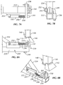
- Figures 17A-17C show side, front, and back views of the reel 50C mounted on a stand 610
- Figures 18A-18C show perspective, front, and side views of the stand 610 without a reel.
- the transport reels 50C mount in the transport stands 610 fastened to a deck of the trailer 550 or the like. This allows a conventional step deck trailer 550 to be used in North America to transport the reels 50C while still meeting the regular transport envelope dictated by law.
- the transport stands 610 allow operators to send a number of reels 50C on a one-way trip to a given destination.
- the transport stands 610 have containment frame or platform 612 connected to a base frame 615 by pivots 614.
- the base frame 615 mounts to the deck of the trailer 550 using known techniques, and the containment frame 612 can pivot relative to the base frame 615 to facilitate loading of the reels 50C onto the stands 610.
- the containment frame 612 can have a central mount for the hub of the reel 50C. At four corners, the containment frame 612 has jointed arms 616 that can collapse inward around the edge of the reel 50C.
- the containment frame 612 lays down closer to the base frame 615 mounted on the deck using short back legs (not shown).
- the jointed arms 616 opened outward, operators use a crane to place the reel 50C in position on the containment frame 612. Then, operators close the jointed arms 616 in around the edges of the reel 50C and can install locking pins (not shown) in the elbows of the jointed arms 616. Operators then connect chains (not shown) diagonally across the reel 50C by affixing the chains to opposing ends 617 of the jointed arms 616.
- the reel 50C and stand 610 encompass an envelope that is approximately 2.5-m. wide and 4-m. high for the reel 50C that is 4.3 m (14-ft) in diameter. This corresponds to a standard transport envelope when a step deck trailer of proper deck height is used in North America. As expected, being able to use standard transport enables operators to reduce overall transport costs.
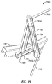
- stands 610 When a number of stands 610 have been collected at a site, operators can make a return shipment of the transport stands 610 without any reels 50C. As shown in Figure 19 , stands 610 can be folded up and stacked on the trailer 550 so the stands 610 can be returned to a distribution center.
- a number of reels 50 can be transported on a one-way trip to a destination.
- the reels 50 can be removed from the stands 610 and transported further or used in the field. Since the transport reels 50 can be transported as break bulk cargo on a ship, for example, there is no need for any transport stands to be used. Therefore, the empty stands 610 can be stored temporarily while the reels 50 are handled separately. Eventually, operators can fold up the stands 610 and stack a number of them on one trailer 550 for a return trip to a distribution center. This arrangement allows operators to reduce transport cost.
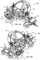
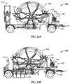
- FIGS 20A-20B transporting and deploying the rod at an installation site uses a dedicated trailer 700.
- the trailer 700 can meet regular road transport envelopes when transporting a reel 50.
- the transport reel 50C in Figures 20A-20B has a fixed cage and frame arrangement, but the trailer 700 can also hold the modular reel 50A discussed previously, as shown for example in Figure 22A .
- the trailer 700 has a trailer body 702 with wheels and a pedestal 750 disposed thereon.
- the transport trailer 700 also has a power system 704, a hydraulic system 706, a guide arm 708, and a deployment unit 710.
- the pedestal 750 which is described in more detail later, affixes to the trailer's body 702 and supports the reel 50 at a slanted angle. When used, the pedestal 750 can articulate the reel 50 on the body 702 and can control rotation of the reel 50.
- the power system 704 can use an electric motor, combustion engine, or the like.
- the hydraulic system 706 has a reservoir, a pump, valves, and other hydraulic components.
- the power system 704 situates at the front of the trailer 700 and provides power for the hydraulic system 706.
- a deployment unit support 720 retains the deployment unit 710, which can be removed from the trailer 700.
- the deployment unit 710 includes a frame 712 that supports a transport unit 714, a rod bender unit 716, and a guide tube 718.
- the transport trailer 700 carries the small reel 50 from a distribution center to a well site.
- operators remove the unit 710 and set it up next to the reel 50.
- the deployment unit 710 can be lifted from the trailer 700 by a crane (not shown) and set up next to the reel 50 when at an installation site.
- the unit 710 acts as an autonomous system to extract the curved rod from the reel 50, straighten the rod, and feed the rod over an extended distance to installation equipment or specific welding equipment.
- the unit 710 can accept the rod from the installation equipment, curve it, and spool the rod back into the transport reel 50.
- the guide tube 718 connects to the guide support 708 and assembles to the rod bender unit 716.
- the guide support 708 attached to the trailer body 702 can be moved relative to the slanted reel 50 to guide rod into and out of the reel 50.
- the trailer 700 and deployment unit 710 feed the continuous rod (described previously) into the guide tube 718, through the bender unit 716, and out the small transfer unit 714.
- the bender unit 716 seeks to sufficiently straighten the rod, which has a deformed curvature from being stored in the reel 50.
- the rod can feed to a gripper system positioned above the wellhead.
- a gripper system can take over the transport of the rod to install it into or out of the well.
- the deployment unit 710 straightens/bends the rod.
- the hub motor (756; Fig. 26C ) of the pedestal 750 deals with the inertia of the rotating reel 50C on the trailer 700.
- the transfer unit 714 can have a roller system with two driven rollers opposing one another or can have a chain gripping system.
- the bender unit 716 can have opposing rollers to deform (bend) the rod as desired.
- the orientation of the bender unit 716 may or may not be adjustable so that the bending that it applies can align with the bend of the rod relative to the reel 50.
- the deployment unit 710 also accepts the rod returned from the well to the transport reel 50. In this direction, the unit coils the rod back into the small transport reel 50.
- This deployment unit 710 can also deliver the rod end of the coiled rod to a welder system positioned at a distance from the wellhead and can return the rod end with the added on features back to the reel 50.
- the bender unit 716 installs on a linkage 715.
- the linkage 715 can swing the bender unit 716 from a transport position ( Fig. 24A ) to an operating position ( Fig. 24B ) so the bender unit 716 can connect by the guide tube 718 to the guide support 708.
- a director 709 can connect to the guide tube 718 to facilitate travel of the rod between the reel 50C and the guide tube 718.
- the transfer unit 714 can slide out from a transport position ( Fig. 24A ) to an operating position ( Fig. 24B ) on a platform 719 installed on the trailer 700.
- the transfer unit 714 slides out independent of the bending unit 716, and an intermediate guide tube 717 connects the bending unit 716 to the transfer unit 718.
- the orientation of the bender unit 716 may or not be adjustable so that the bending that it applies can align with the bend of the rod relative to the reel 50C.
- the transfer unit 714 and the bender unit 716 can be connected to each other such that they can be deployed together by a single action, such as pivoting on a linkage. Moreover, the units 714 and 716 can be deployed so that there is as little space between them as practical. In general, deployment of the transfer unit 714 and the bender unit 716 for any of the various configurations can be achieved manually or automatically (i.e., using a hydraulic actuator or the like).
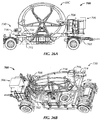
- Figs. 26A-26B show side and perspective views of the transport trailer 700 with the transport reel 50C and third transfer components 730.
- the bender unit 716 installs on an arm 732 connected to a linkage 715 on the trailer 700.
- the bender unit 716 can pivot on the arm 732, and the arm 732 can swing out from the trailer 700 from a transport position ( Fig. 26A ) to an operating position ( Fig. 26B ).
- the bender unit 716 can connect by the guide tube 718 to the guide support 708.
- the transfer unit 714 installs on a slide 734 that can extend out from the trailer 700.
- the transfer unit 714 can pivot on this slide 734 and can slide out from a transport position ( Fig. 26A ) to an operating position ( Fig. 26B ).
- the bender unit 716 and transfer unit 714 are coupled together, and they move in tandem between transport and operating positions. This allows for a single action (manual or automatic) to move the transfer components 730 and keeps the distance between the units 714 and 716 to a minimum.
- the orientation of the bender unit 716 may or may not be adjustable so that the bending that it applies can align with the bend of the rod relative to the reel 50C.
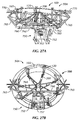
- Figures 27A-27C show various views of the pedestal 750 with a reel mounted thereon.
- the reel is actually a modular reel 50A as described previously and having separable cage 100 and frame 200, although as disclosed herein a fixed reel could also be used.
- the pedestal 750 on which the reel 50A mounts has a base 752 with an articulating mount 754.
- the base 752 can affix or mount in a number of ways on the transport vehicle. As shown in previous Figures, the base 752 can attach to I-beams on the trailer's body (702).
- the mount 754 connects by pivots 753 to the base 752, which allows the mount 754 with reel 50A to articulate.
- a telescoping support bar 755 is shown in Figures 27A-27C connected between the base 752 and the mount 754. This telescoping support bar 755 can be extended or collapsed to the desired length and then pinned in place to support the orientation of the mount 754.
- the piston 757 connects between the base 752 and mount 754 to articulate the mount 754 hydraulically when the bar 755 is unpinned.
- the articulating mount 754 can pivot relative to the base 752 so the angle of the reel 50A can be changed as needed during operation.
- an integrated brake (not visible) can be used to brake the rotation of the reel 50A.
- Side arms 760 extend from opposite sides of the articulating base 754.
- the arms 760 include upward angled elbows 765 that fit around the edge of the reel 50A. These angled elbows 765 can move in and out of the fixed arms 760 to install, enclose, and remove the reel 50A.
- Pistons 762 connect to the elbow 765 and the arms 760 to position the elbows 765 in place.
- Gates can be used as the rod is wound out of (and into) the reel 50 on the trailer 700 to selectively close and open the slot around the top of the reel 50.
- the elbows 765 can have posts on their tips on which forked wheels 770 can be provided to close off the open slot 165 around the top of the reel 50A.
- the outer uprights 120 on the reel's cage 10 intermittently engage blades of the forked wheels 770 on the opposing side arms 760.
- the blades of the wheel 770 consistently cover the open slot 165 defined around the reel 50A where the rod is intended to pass out of the cage 100. By keeping portions of this slot 165 covered, the blades of the wheel 770 can keep the rod inside the cage 100. As described below, other devices can be used to close the cage's slot 165 to prevent premature escape of the rod from the reel.
- a transport reel in this example fixed 50C, although a modular reel could be used
- passive gates 780 selectively open and close due to the rotation of the transport reel 50.
- at least two of the inner uprights 68 on the reel 50C have gates 780 mounted thereon.
- the gate 780 includes an upward stem 782 that fits adjacent the reel's inner upright (68).
- a bracket member 787 connects by frame elements 789 to the upward stem 782.
- the bracket 787 fits onto the angled bar of the reel's arm (64).
- the upward stem 782 has an axle 784 between upper and lower joints 785a-b that allow the axle 784 to rotate relative to the stem 782.
- the axle 784 has a cross bar 786 on its upward end and has a fan bar 788 on its lower end.
- These gates 780 provide a defined opening of the cage's open slot 65 for the passage of rod into and out of the transport reel 50C.
- two bars 764/766 extend in opposite directions from one of the pedestals side arms 760.
- the bars 764/766 are offset from one another, and each has an upward projecting tip.
- the gates 780 on the reel 50C move relative to these bars 764/766.
- one of the fan bars 788 on one of the gates 780 engages the tip on one of the bars 764. This turns the fan bar 788 and the connected cross bar 786 to open the slot 65 at this portion around the reel 50C.
- a section of the slot 65 can be opened around the reel 50C as it turns on the pedestal 750 while the remainder stays covered by the gates 780.
- the gates 780 can prevent premature escape of the rod from the reel 50C.
- These gates 780 can be used in place of or in addition to other closure devices, such as the forked wheels 770.
Landscapes
- Engineering & Computer Science (AREA)
- Mechanical Engineering (AREA)
- Geology (AREA)
- Life Sciences & Earth Sciences (AREA)
- Mining & Mineral Resources (AREA)
- General Life Sciences & Earth Sciences (AREA)
- Fluid Mechanics (AREA)
- Environmental & Geological Engineering (AREA)
- Physics & Mathematics (AREA)
- Geochemistry & Mineralogy (AREA)
- Health & Medical Sciences (AREA)
- Public Health (AREA)
- Transportation (AREA)
- Storage Of Web-Like Or Filamentary Materials (AREA)
- Handcart (AREA)
- Unwinding Of Filamentary Materials (AREA)
Claims (15)
- Transportsystem für durchgehende Stangen, das aufweist:einen Ständer (604, 610, 750) mit einer Basis (615, 752) und einer Plattform (612, 754), wobei die Plattform (612, 754) relativ zur Basis (615, 752) gelenkig befestigt ist und eine Rolle (50) für die durchgehende Stange (R) darauf trägt; undeine Einsatzeinheit (600, 602, 710), die benachbart der Rolle (50) angeordnet ist, wobei die Einsatzeinheit (600, 602, 710) eine Stangenübertragungseinheit (714), die funktionsfähig ist, um die durchgehende Stange (R) entlang ihrer axialen Länge von einer Quelle aus zu transportieren, und eine Stangenbiegeeinheit (716) aufweist, die funktionsfähig ist, um die transportierte Stange (R) unter einem Winkel relativ zu ihrer axialen Länge dauerhaft zu biegen, bevor die Stange (R) in der Rolle (50) aufgewickelt wird, wobei die Einsatzeinheit (600, 602, 710) einen ersten Modus und einen zweiten Modus aufweist, wobei die Einsatzeinheit (600, 602, 710) im ersten Modus die Stangenübertragungseinheit (714) und die Stangenbiegeeinheit (716) betätigt, um die gebogene Stange (R) einige Male in der Rolle (50) aufzuwickeln, und wobei sie im zweiten Modus die Stangenübertragungseinheit (714) betätigt und nicht die Stangenbiegeinheit (716), um mit dem dauerhaften Biegen der transportierten Stange (R) unter einem Winkel aufzuhören, nachdem die Stange (R) einige Male in der Rolle (50) aufgewickelt wurde.
- System nach Anspruch 1, bei dem die Plattform (754) drehbar die Rolle (50) darauf trägt, und wobei das System wahlweise außerdem einen Motor (756) aufweist, der auf der Plattform (754) angeordnet und mit einem Rad gekuppelt ist, an dem die Rolle (50) drehbar getragen wird, wobei der Motor (756) die Drehung der Rolle (50) steuert.
- System nach Anspruch 1 oder 2, das außerdem einen Kolben (757) aufweist, der zwischen der Basis (752) und der Plattform (754) gekuppelt ist, und wobei die Plattform (754) relativ zur Basis (752) gedreht wird.
- System nach Anspruch 1, 2 oder 3, bei dem die Plattform (612, 754) Arme (616, 760) aufweist, die sich von dort aus erstrecken und Enden (617, 765) aufweisen, die einen Rand der Rolle (50) umschließen, und wobei wahlweise mindestens eines von:den Enden (617) an den Armen (616) relativ zum Rand beweglich ist; undden Enden (765) Räder (770) aufweist, die drehbar daran angeordnet sind, wobei die Räder (770) Schaufeln aufweisen, die mit einem Teil der Rolle (50) in Eingriff kommen und sich durch den Eingriff mit der Rolle (50) drehen.
- System nach einem der vorhergehenden Ansprüche, das außerdem einen Anhänger (550, 700) aufweist, der den Ständer (610, 750) trägt.
- System nach Anspruch 5, bei dem der Anhänger (700) ein Hydrauliksystem (706) und eine Leistungseinheit (704) aufweist, die dem Hydrauliksystem (706) eine Leistung zuführt.
- System nach Anspruch 5 oder 6, bei dem der Anhänger (700) die Einsatzeinheit (710) aufweist, die darauf für ein Bewegen der durchgehenden Stange (R) relativ zur Rolle (50) angeordnet ist; wobei wahlweise mindestens eine der:Stangenübertragungseinheit (714) und der Stangenbiegeeinheit (716) funktionsfähig ist, um die Stange (R) dazwischen zu verbinden, wobei die Stangenübertragungseinheit (714) die Stange (R) relativ zur Rolle (50) bewegt, und wobei die Stangenbiegeeinheit (716) die Stange (R) biegt, die bewegt wird, und wobei wahlweise außerdem mindestens eines davon zu verzeichnen ist, dass:das System außerdem ein Führungsrohr (718) aufweist, das benachbart der Rolle (50) und verbunden mit der Einsatzeinheit (710) positioniert ist und die durchgehende Stange (R) dazwischen führt;die Einsatzeinheit (710) einen Rahmen (712) aufweist, der entfernbar am Anhänger montiert werden kann; undmindestens ein Abschnitt der Einsatzeinheit (710) am Anhänger (700) montiert ist und relativ zum Anhänger (700) schwenkt.
- System nach einem der vorhergehenden Ansprüche, das außerdem einen Durchlass (780) aufweist, der auf der Rolle (50) angeordnet ist und sich selektiv über einem Durchgang (65) in der Rolle (50) für die darin aufgewickelte durchgehende Stange (R) öffnet und schließt,
wobei wahlweise der Durchlass (780) einen ersten Stab (786) aufweist, der drehbar mit einem zweiten Stab (788) verbunden ist, wobei sich der erste Stab (786) selektiv über dem Durchgang (65) öffnet und schließt, wenn er durch den zweiten Stab (788) gedreht wird; und
wobei wahlweise außerdem der Ständer (750) eine erste Stelle (764), die mit dem zweiten Stab (788) in Eingriff kommt, wenn sich die Rolle (50) relativ dazu dreht und den ersten Stab (786) über dem Durchgang (65) öffnet, und eine zweite Stelle (766) aufweist, die mit dem zweiten Stab (788) in Eingriff kommt, wenn sich die Rolle relativ dazu dreht und die erste Stange (764) über dem Durchgang (65) schließt. - System nach Anspruch 1, das außerdem einen Transportanhänger (700) für die Rolle (50) der durchgehenden Stange (R) aufweist, wobei der Transportanhänger (700) aufweist:eine Karosserie (702), die von Rädern getragen wird, wobei der Ständer (750) an der Karosserie (702) getragen wird und die Rolle (50) für die durchgehende Stange (R) daran drehbar trägt; unddie Einsatzeinheit (710), die an der Karosserie (702) angeordnet ist, wobei die Einsatzeinheit (710) funktionsfähig ist, um die Stange (R) relativ zur Rolle (50) zu biegen und zu bewegen.
- System nach Anspruch 9, bei dem mindestens eine von:der Stangenübertragungseinheit (714) und der Stangenbiegeeinheit (716) funktionsfähig ist, um die Stange (R) dazwischen zu verbinden, wobei die Stangenübertragungseinheit (714) die Stange relativ zur Rolle (50) bewegt, und wobei die Stangenbiegeeinheit (716) die Stange (R) biegt, die bewegt wird;der Einsatzeinheit (710) einen Rahmen (712) aufweist, der entfernbar an der Karosserie (702) des Anhängers (700) montiert werden kann, wobei wahlweise der Rahmen (712) die Stangenbiegeeinheit (716) benachbart der Stangenübertragungseinheit (714) hält und ein Führungsrohr (718) daran lagert;mindestens einem Abschnitt der Einsatzeinheit (710) am Anhänger (700) montiert ist und sich relativ zur Rolle (50) bewegt;der Stangenbiegeeinheit (716) an einem Arm (715, 732) angeordnet ist, wobei der Arm (715, 732) schwenkbar an der Karosserie (702) des Anhängers (700) befestigt und funktionsfähig ist, um die Stangenbiegeeinheit (716) relativ zur Rolle (50) zu schwenken;der Stangenübertragungseinheit (714) auf einer Plattform (719, 734) angeordnet ist, wobei die Plattform (719, 734) verschiebbar an der Karosserie (702) des Anhängers (700) befestigt und funktionsfähig ist, um die Stangenübertragungseinheit (714) relativ zur Rolle (50) zu verschieben.
- System nach Anspruch 1, bei dem der Ständer ein Transportständer (610) des Anhängers für die Rolle (50) der durchgehenden Stange (R) ist, wobei die Basis (615) auf einem Unterbau des Anhängers (550) angeordnet ist, wobei die Plattform (612) schwenkbar mit der Basis (615) verbunden ist und darauf die Rolle (50) für die durchgehende Stange (R) trägt, wobei der Ständer (610) außerdem aufweist:mindestens eine Auflage (618), die entfernbar zwischen der Plattform (612) und der Basis (615) angeordnet ist und die Plattform (612) unter einem Winkel relativ zur Basis (615) hält; undeine Vielzahl von Armen (616), die mit der Plattform (612) verbunden und schwenkbar nach innen zur Plattform (612) um den Rand der Rolle (50) ist.
- Ständer nach Anspruch 11, bei dem mindestens eines von Folgendem zu verzeichnen ist:die Plattform (612) klappt gegen die Basis (615) zusammen, und die Arme (616) schwenken von der Plattform (612) nach außen;die Enden (617) der Arme (612) befestigen sich aneinander über die Rolle (50), die auf der Plattform (612) getragen wird; unddie Plattform (612) weist eine Halterung (613) auf, an der eine Nabe der Rolle (50) befestigt ist.
- Verfahren zum Aufwickeln der durchgehenden Stange (R) von einer Quelle in eine Transportrolle (50) für das Halten der aufgewickelten Stange (R), wobei das Verfahren die folgenden Schritte aufweist:Transportieren der durchgehenden Stange (R) entlang ihrer axialen Länge von der Quelle;dauerhaftes Biegen der transportierten Stange (R) unter einem Winkel relativ zu ihrer axialen Länge vor dem Aufwickeln der Stange (R) in der Transportrolle (50);Aufwickeln der gebogenen Stange (R) mehrmals in der Transportrolle (50);Beenden des Schrittes des dauerhaften Biegens der transportierten Stange (R) unter einem Winkel, nachdem die Stange (R) mehrmals in der Transportrolle (50) aufgewickelt wurde; undFortsetzen des Aufwickelns der transportierten Stange (R) in der Transportrolle (50) ohne dauerhaftes Biegen der Stange (R) vor dem Aufwickeln in der Transportrolle (50).
- Verfahren nach Anspruch 13, das außerdem den Schritt des Abwickelns der durchgehenden Stange (R) von der Transportrolle (50) zu einem Bestimmungsort aufweist.
- Verfahren nach Anspruch 14, bei dem das Abwickeln der durchgehenden Stange (R) von der Transportrolle (50) zum Bestimmungsort die folgenden Schritte aufweist:Abwickeln der durchgehenden Stange (R) von der Transportrolle (50);bleibendes Begradigen der abgewickelten Stange (R) relativ zu ihrer axialen Länge; undTransportieren der begradigten Stange (R) zum Bestimmungsort.
Applications Claiming Priority (1)
| Application Number | Priority Date | Filing Date | Title |
|---|---|---|---|
| US12/912,848 US8869580B2 (en) | 2009-09-28 | 2010-10-27 | Continuous rod transport system |
Publications (3)
| Publication Number | Publication Date |
|---|---|
| EP2447464A2 EP2447464A2 (de) | 2012-05-02 |
| EP2447464A3 EP2447464A3 (de) | 2013-10-09 |
| EP2447464B1 true EP2447464B1 (de) | 2016-03-30 |
Family
ID=44862736
Family Applications (1)
| Application Number | Title | Priority Date | Filing Date |
|---|---|---|---|
| EP11186976.4A Active EP2447464B1 (de) | 2010-10-27 | 2011-10-27 | Transportsystem für durchgehende Stangen |
Country Status (4)
| Country | Link |
|---|---|
| US (3) | US8869580B2 (de) |
| EP (1) | EP2447464B1 (de) |
| AU (1) | AU2011236064B2 (de) |
| CA (1) | CA2756358C (de) |
Families Citing this family (23)
| Publication number | Priority date | Publication date | Assignee | Title |
|---|---|---|---|---|
| US8869580B2 (en) * | 2009-09-28 | 2014-10-28 | Weatherford/Lamb, Inc. | Continuous rod transport system |
| US9527153B2 (en) | 2013-03-14 | 2016-12-27 | Lincoln Global, Inc. | Camera and wire feed solution for orbital welder system |
| DE202013008357U1 (de) * | 2013-09-13 | 2013-11-18 | Ball Europe Gmbh | Behälterdose und Halteeinrichtung |
| CA2841375A1 (en) * | 2013-10-03 | 2015-04-03 | C-Tech Oil Well Technologies Inc. | Coiled rod reel |
| US9770775B2 (en) | 2013-11-11 | 2017-09-26 | Lincoln Global, Inc. | Orbital welding torch systems and methods with lead/lag angle stop |
| US9517524B2 (en) | 2013-11-12 | 2016-12-13 | Lincoln Global, Inc. | Welding wire spool support |
| US9731385B2 (en) | 2013-11-12 | 2017-08-15 | Lincoln Global, Inc. | Orbital welder with wire height adjustment assembly |
| WO2016176619A1 (en) * | 2015-04-29 | 2016-11-03 | Mick Zoske | Hose mover |
| CN105347100B (zh) * | 2015-11-19 | 2018-12-28 | 东南大学 | 一种组装式拉索放线盘 |
| CA2963747A1 (en) * | 2016-04-08 | 2017-10-08 | 925599 Alberta Ltd. | Method and apparatus for coiling a continuous rod |
| CA3078701C (en) * | 2016-04-08 | 2022-04-12 | Flexsteel Pipeline Technologies, Inc. | Pipe deployment trailer |
| US10654395B1 (en) | 2016-04-08 | 2020-05-19 | Trinity Bay Equipment Holdings, LLC | Pipe deployment trailer |
| US10981749B2 (en) | 2016-06-28 | 2021-04-20 | Trinity Bay Equipment Holdings, LLC | Half-moon lifting device |
| US10981765B2 (en) | 2016-06-28 | 2021-04-20 | Trinity Bay Equipment Holdings, LLC | Half-moon lifting device |
| CN106249997B (zh) * | 2016-07-27 | 2019-08-13 | 北京小米移动软件有限公司 | 桌面页显示方法及装置 |
| US10392875B2 (en) | 2016-09-30 | 2019-08-27 | Weatherford Technology Holdings, Llc | Gripper assembly for continuous rod and methods of use thereof |
| CN107934647B (zh) * | 2017-12-22 | 2019-06-04 | 国网河北省电力有限公司安平县供电分公司 | 一种供电所施工辅助放线装置 |
| CN111902354A (zh) | 2018-03-27 | 2020-11-06 | 山特维克原料技术德国公开股份有限公司 | 用于线材或板材的运输系统和用于供应线材或板材的方法 |
| EP4431426A3 (de) * | 2018-03-27 | 2024-11-27 | Alleima GmbH | Transportsystem für ein rohr und verfahren zum ausliefern eines rohrs |
| NL2023074B1 (en) * | 2019-05-06 | 2020-11-30 | Itrec Bv | Modular spool storage device, modular support structure and combination thereof |
| CN110835002A (zh) * | 2019-11-14 | 2020-02-25 | 国网山东省电力公司临沂供电公司 | 一种电力线缆放线装置 |
| CN111236867B (zh) * | 2020-01-13 | 2021-09-21 | 临沂德胜机械有限公司 | 一种液压强化传动动力流畅的数字化连续油管注入设备 |
| CN111622693A (zh) * | 2020-04-10 | 2020-09-04 | 四川宏华石油设备有限公司 | 一种连续油管滚筒 |
Family Cites Families (42)
| Publication number | Priority date | Publication date | Assignee | Title |
|---|---|---|---|---|
| CA885866A (en) | 1971-11-16 | Corod Manufacturing Ltd. | Transport reel | |
| US3186659A (en) * | 1963-05-27 | 1965-06-01 | Carter H Arnold | Device for coiling and storing wire rope and the like |
| US3254851A (en) * | 1963-12-27 | 1966-06-07 | Charles B Caperton | Drive for rodding machine |
| US3270979A (en) * | 1964-12-14 | 1966-09-06 | Donald P Whitacre | Wire coiling machine having grooved block |
| US3561034A (en) * | 1966-12-30 | 1971-02-09 | Charles B Caperton | Sewer rodding machine |
| US3491967A (en) * | 1967-08-28 | 1970-01-27 | James L Sawyer | Mobile apparatus for dispensing coiled cable and the like |
| US3559905A (en) * | 1968-01-09 | 1971-02-02 | Corod Mfg Ltd | roeder; Werner H. |
| US3504866A (en) * | 1968-05-06 | 1970-04-07 | Corod Mfg Ltd | Transport reel |
| US3480983A (en) * | 1969-01-29 | 1969-12-02 | Charles B Caperton | Drive for rodding machine |
| US3627224A (en) * | 1970-01-05 | 1971-12-14 | Richard E Diggs | Reel device |
| DE2006840A1 (en) | 1970-02-14 | 1971-09-02 | Corod Manufacturing Ltd , Edmonton, Alberta (Kanada) | Road transporter for coiled well rods |
| US3655218A (en) * | 1970-05-19 | 1972-04-11 | Louis Dale Taylor | Apparatus for transporting heavy objects |
| US3626734A (en) * | 1970-06-10 | 1971-12-14 | Blaw Knox Foundry Mill Machine | Bar coiler |
| US3923469A (en) * | 1972-09-01 | 1975-12-02 | Corod Mfg Ltd | One-fold unitary steel sucker rod string |
| DE2333435A1 (de) | 1973-06-30 | 1975-01-16 | Werner Cielker | Einziehgeraet |
| FR2342865A1 (fr) | 1976-02-18 | 1977-09-30 | Haussy Armand | Pupitre articule |
| GB2064704B (en) * | 1979-12-12 | 1984-07-04 | Homersham B R Ltd | Hose loop support |
| US4412438A (en) * | 1981-07-24 | 1983-11-01 | Gosudarstvenny Nauchnoissledovatelsky, Proektny I Konstruktorsky Institut Splavov I Obrabotki Tsvetnykh Metallov "Giprotsvetmetobrabotka" | Pipe bending machine |
| US4416329A (en) * | 1981-08-13 | 1983-11-22 | Henlan, Inc. | Oil well setup and pumping apparatus |
| US4471651A (en) * | 1982-11-12 | 1984-09-18 | Mark Telephone Products, Inc. | Duct probe and dispensing apparatus therefor |
| US4767073A (en) * | 1984-09-10 | 1988-08-30 | Malzacher Fred H | Cable spooling system |
| JPS62134114A (ja) * | 1985-12-06 | 1987-06-17 | Nippon Steel Corp | 線材の巻取方法 |
| US4673035B1 (en) * | 1986-01-06 | 1999-08-10 | Plains Energy Services Ltd | Method and apparatus for injection of tubing into wells |
| EP0266206A1 (de) | 1986-10-31 | 1988-05-04 | Erico International Corporation | Erdungstäbe und Verfahren und Vorrichtung zum Formen und Einbringen dieser Stäbe |
| US4945938A (en) * | 1989-09-22 | 1990-08-07 | Otis Engineering Corporation | Reels and carriers therefor |
| US5404757A (en) * | 1990-03-20 | 1995-04-11 | Etat Francais Represented By Laboratoire Central Des Ponts Et Chaussees | Device for driving rods used primarily for soil mechanics tests into the ground |
| US5215272A (en) * | 1991-01-30 | 1993-06-01 | Sauber Charles J | Winding device having a tilting table and method |
| FR2707221A1 (fr) | 1993-07-05 | 1995-01-13 | Efsa | Véhicule de transport d'au moins une bobine. |
| FR2726321B1 (fr) * | 1994-11-02 | 1996-11-29 | Inst Francais Du Petrole | Dispositif de stockage et de manutention d'une tige en materiau composite |
| GB2345282B (en) * | 1998-12-30 | 2001-09-05 | Kim Jum Gyu | Variable height container for vessel |
| US6347761B1 (en) * | 2000-07-28 | 2002-02-19 | Rick E. Larson | Mobile cable dispensing system |
| US6481082B1 (en) * | 2000-08-28 | 2002-11-19 | 768885 Alberta Ltd. | Portable continuous sucker rod manufacturing process |
| DE20019547U1 (de) | 2000-11-17 | 2001-03-01 | VETEC GmbH Verbindungstechnologie für Versorgungssysteme, 97497 Dingolshausen | Verbindungsvorrichtung von einer Rohrhaspel mit einem Rohrrichtgerät |
| CA2390054C (en) * | 2002-06-28 | 2013-03-19 | Weatherford Canada Partnership | Method for manufacturing continuous sucker rod |
| US7290756B2 (en) * | 2004-07-19 | 2007-11-06 | Pavlov Michael V | Concertina tape products configured for stable deployment and retrieval |
| US8191637B2 (en) * | 2005-12-05 | 2012-06-05 | Xtreme Coil Drilling Corp. | Method and apparatus for conducting earth borehole operations |
| US20080196235A1 (en) * | 2007-02-16 | 2008-08-21 | Rick Gereluk | Corrosion protection of continuous sucker rod weld zones |
| NO332373B1 (no) | 2008-08-13 | 2012-09-03 | C6 Technologies As | Spolesammenstilling for et langstrakt element |
| AU2008100774B4 (en) | 2008-08-15 | 2009-06-25 | Boreboss Pty Ltd | Transportable pumping apparatus |
| US20100308147A1 (en) * | 2009-06-03 | 2010-12-09 | Randel Brandstrom | Fiber reinforced rebar formed into a coil for transportation |
| US8869580B2 (en) * | 2009-09-28 | 2014-10-28 | Weatherford/Lamb, Inc. | Continuous rod transport system |
| US8864428B2 (en) * | 2009-09-28 | 2014-10-21 | Weatherford/Lamb, Inc. | Continuous rod transport system |
-
2010
- 2010-10-27 US US12/912,848 patent/US8869580B2/en active Active
-
2011
- 2011-10-17 AU AU2011236064A patent/AU2011236064B2/en not_active Ceased
- 2011-10-26 CA CA2756358A patent/CA2756358C/en active Active
- 2011-10-27 EP EP11186976.4A patent/EP2447464B1/de active Active
-
2014
- 2014-09-30 US US14/502,395 patent/US9637038B2/en active Active
- 2014-09-30 US US14/502,435 patent/US9873366B2/en active Active
Also Published As
| Publication number | Publication date |
|---|---|
| US9637038B2 (en) | 2017-05-02 |
| EP2447464A3 (de) | 2013-10-09 |
| AU2011236064A1 (en) | 2012-05-17 |
| AU2011236064B2 (en) | 2015-04-09 |
| US9873366B2 (en) | 2018-01-23 |
| CA2756358A1 (en) | 2012-04-27 |
| US20110072874A1 (en) | 2011-03-31 |
| US20150014462A1 (en) | 2015-01-15 |
| EP2447464A2 (de) | 2012-05-02 |
| US8869580B2 (en) | 2014-10-28 |
| US20150016915A1 (en) | 2015-01-15 |
| CA2756358C (en) | 2015-12-15 |
Similar Documents
| Publication | Publication Date | Title |
|---|---|---|
| EP2447464B1 (de) | Transportsystem für durchgehende Stangen | |
| CA2869925C (en) | Continuous rod transport system | |
| CN109996749B (zh) | 用于盘卷的柔性管的安装拖车及其使用方法 | |
| AU2020202276B2 (en) | Pipe deployment trailer | |
| US10654395B1 (en) | Pipe deployment trailer | |
| US11613443B2 (en) | Mobile cradle frame for pipe reel | |
| AU2004289581B2 (en) | A method and device for reel transport | |
| US20050023404A1 (en) | Deep-well, continuous-coiled-tubing apparatus and method of use | |
| AU2018309046A1 (en) | System and method for a flexible pipe containment sled | |
| US20160362950A1 (en) | Dual-Reel Assembly For Coiled Tubing | |
| US11407164B2 (en) | Rerounder system | |
| HK40010337A (en) | Installation trailer for coiled flexible pipe and method of utilizing same | |
| HK40000208A (zh) | 管道展开拖车 |
Legal Events
| Date | Code | Title | Description |
|---|---|---|---|
| PUAI | Public reference made under article 153(3) epc to a published international application that has entered the european phase |
Free format text: ORIGINAL CODE: 0009012 |
|
| 17P | Request for examination filed |
Effective date: 20111027 |
|
| AK | Designated contracting states |
Kind code of ref document: A2 Designated state(s): AL AT BE BG CH CY CZ DE DK EE ES FI FR GB GR HR HU IE IS IT LI LT LU LV MC MK MT NL NO PL PT RO RS SE SI SK SM TR |
|
| AX | Request for extension of the european patent |
Extension state: BA ME |
|
| RIC1 | Information provided on ipc code assigned before grant |
Ipc: B65H 75/36 20060101ALI20130425BHEP Ipc: B21C 47/24 20060101ALI20130425BHEP Ipc: B21C 47/04 20060101ALI20130425BHEP Ipc: B21C 47/28 20060101ALI20130425BHEP Ipc: B65H 75/22 20060101ALI20130425BHEP Ipc: B65H 75/20 20060101ALI20130425BHEP Ipc: B65H 49/38 20060101ALI20130425BHEP Ipc: B60P 3/035 20060101ALI20130425BHEP Ipc: E21B 19/22 20060101AFI20130425BHEP |
|
| PUAL | Search report despatched |
Free format text: ORIGINAL CODE: 0009013 |
|
| AK | Designated contracting states |
Kind code of ref document: A3 Designated state(s): AL AT BE BG CH CY CZ DE DK EE ES FI FR GB GR HR HU IE IS IT LI LT LU LV MC MK MT NL NO PL PT RO RS SE SI SK SM TR |
|
| AX | Request for extension of the european patent |
Extension state: BA ME |
|
| RIC1 | Information provided on ipc code assigned before grant |
Ipc: B65H 49/38 20060101ALI20130905BHEP Ipc: B65H 75/22 20060101ALI20130905BHEP Ipc: B21C 47/04 20060101ALI20130905BHEP Ipc: B21C 47/28 20060101ALI20130905BHEP Ipc: B65H 75/20 20060101ALI20130905BHEP Ipc: B65H 75/36 20060101ALI20130905BHEP Ipc: B21C 47/24 20060101ALI20130905BHEP Ipc: B60P 3/035 20060101ALI20130905BHEP Ipc: E21B 19/22 20060101AFI20130905BHEP |
|
| 17Q | First examination report despatched |
Effective date: 20140429 |
|
| RAP1 | Party data changed (applicant data changed or rights of an application transferred) |
Owner name: WEATHERFORD/LAMB, INC. |
|
| RAP1 | Party data changed (applicant data changed or rights of an application transferred) |
Owner name: WEATHERFORD TECHNOLOGY HOLDINGS, LLC |
|
| GRAP | Despatch of communication of intention to grant a patent |
Free format text: ORIGINAL CODE: EPIDOSNIGR1 |
|
| RIC1 | Information provided on ipc code assigned before grant |
Ipc: B21C 47/04 20060101ALI20150907BHEP Ipc: B65H 75/20 20060101ALI20150907BHEP Ipc: B65H 75/36 20060101ALI20150907BHEP Ipc: B21C 47/24 20060101ALI20150907BHEP Ipc: B65H 75/44 20060101ALI20150907BHEP Ipc: B60P 3/035 20060101ALI20150907BHEP Ipc: B65H 49/38 20060101ALI20150907BHEP Ipc: B65H 75/22 20060101ALI20150907BHEP Ipc: E21B 19/22 20060101AFI20150907BHEP Ipc: B21C 47/28 20060101ALI20150907BHEP |
|
| INTG | Intention to grant announced |
Effective date: 20150921 |
|
| GRAS | Grant fee paid |
Free format text: ORIGINAL CODE: EPIDOSNIGR3 |
|
| GRAA | (expected) grant |
Free format text: ORIGINAL CODE: 0009210 |
|
| AK | Designated contracting states |
Kind code of ref document: B1 Designated state(s): AL AT BE BG CH CY CZ DE DK EE ES FI FR GB GR HR HU IE IS IT LI LT LU LV MC MK MT NL NO PL PT RO RS SE SI SK SM TR |
|
| REG | Reference to a national code |
Ref country code: GB Ref legal event code: FG4D |
|
| REG | Reference to a national code |
Ref country code: CH Ref legal event code: EP |
|
| REG | Reference to a national code |
Ref country code: AT Ref legal event code: REF Ref document number: 785629 Country of ref document: AT Kind code of ref document: T Effective date: 20160415 |
|
| REG | Reference to a national code |
Ref country code: IE Ref legal event code: FG4D |
|
| REG | Reference to a national code |
Ref country code: DE Ref legal event code: R096 Ref document number: 602011024553 Country of ref document: DE |
|
| REG | Reference to a national code |
Ref country code: RO Ref legal event code: EPE |
|
| REG | Reference to a national code |
Ref country code: LT Ref legal event code: MG4D |
|
| PG25 | Lapsed in a contracting state [announced via postgrant information from national office to epo] |
Ref country code: GR Free format text: LAPSE BECAUSE OF FAILURE TO SUBMIT A TRANSLATION OF THE DESCRIPTION OR TO PAY THE FEE WITHIN THE PRESCRIBED TIME-LIMIT Effective date: 20160701 Ref country code: HR Free format text: LAPSE BECAUSE OF FAILURE TO SUBMIT A TRANSLATION OF THE DESCRIPTION OR TO PAY THE FEE WITHIN THE PRESCRIBED TIME-LIMIT Effective date: 20160330 Ref country code: FI Free format text: LAPSE BECAUSE OF FAILURE TO SUBMIT A TRANSLATION OF THE DESCRIPTION OR TO PAY THE FEE WITHIN THE PRESCRIBED TIME-LIMIT Effective date: 20160330 Ref country code: NO Free format text: LAPSE BECAUSE OF FAILURE TO SUBMIT A TRANSLATION OF THE DESCRIPTION OR TO PAY THE FEE WITHIN THE PRESCRIBED TIME-LIMIT Effective date: 20160630 |
|
| REG | Reference to a national code |
Ref country code: NL Ref legal event code: MP Effective date: 20160330 |
|
| REG | Reference to a national code |
Ref country code: AT Ref legal event code: MK05 Ref document number: 785629 Country of ref document: AT Kind code of ref document: T Effective date: 20160330 |
|
| PG25 | Lapsed in a contracting state [announced via postgrant information from national office to epo] |
Ref country code: SE Free format text: LAPSE BECAUSE OF FAILURE TO SUBMIT A TRANSLATION OF THE DESCRIPTION OR TO PAY THE FEE WITHIN THE PRESCRIBED TIME-LIMIT Effective date: 20160330 Ref country code: RS Free format text: LAPSE BECAUSE OF FAILURE TO SUBMIT A TRANSLATION OF THE DESCRIPTION OR TO PAY THE FEE WITHIN THE PRESCRIBED TIME-LIMIT Effective date: 20160330 Ref country code: LV Free format text: LAPSE BECAUSE OF FAILURE TO SUBMIT A TRANSLATION OF THE DESCRIPTION OR TO PAY THE FEE WITHIN THE PRESCRIBED TIME-LIMIT Effective date: 20160330 Ref country code: LT Free format text: LAPSE BECAUSE OF FAILURE TO SUBMIT A TRANSLATION OF THE DESCRIPTION OR TO PAY THE FEE WITHIN THE PRESCRIBED TIME-LIMIT Effective date: 20160330 |
|
| PG25 | Lapsed in a contracting state [announced via postgrant information from national office to epo] |
Ref country code: NL Free format text: LAPSE BECAUSE OF FAILURE TO SUBMIT A TRANSLATION OF THE DESCRIPTION OR TO PAY THE FEE WITHIN THE PRESCRIBED TIME-LIMIT Effective date: 20160330 |
|
| PG25 | Lapsed in a contracting state [announced via postgrant information from national office to epo] |
Ref country code: EE Free format text: LAPSE BECAUSE OF FAILURE TO SUBMIT A TRANSLATION OF THE DESCRIPTION OR TO PAY THE FEE WITHIN THE PRESCRIBED TIME-LIMIT Effective date: 20160330 Ref country code: PL Free format text: LAPSE BECAUSE OF FAILURE TO SUBMIT A TRANSLATION OF THE DESCRIPTION OR TO PAY THE FEE WITHIN THE PRESCRIBED TIME-LIMIT Effective date: 20160330 Ref country code: IS Free format text: LAPSE BECAUSE OF FAILURE TO SUBMIT A TRANSLATION OF THE DESCRIPTION OR TO PAY THE FEE WITHIN THE PRESCRIBED TIME-LIMIT Effective date: 20160730 |
|
| PG25 | Lapsed in a contracting state [announced via postgrant information from national office to epo] |
Ref country code: AT Free format text: LAPSE BECAUSE OF FAILURE TO SUBMIT A TRANSLATION OF THE DESCRIPTION OR TO PAY THE FEE WITHIN THE PRESCRIBED TIME-LIMIT Effective date: 20160330 Ref country code: ES Free format text: LAPSE BECAUSE OF FAILURE TO SUBMIT A TRANSLATION OF THE DESCRIPTION OR TO PAY THE FEE WITHIN THE PRESCRIBED TIME-LIMIT Effective date: 20160330 Ref country code: SM Free format text: LAPSE BECAUSE OF FAILURE TO SUBMIT A TRANSLATION OF THE DESCRIPTION OR TO PAY THE FEE WITHIN THE PRESCRIBED TIME-LIMIT Effective date: 20160330 Ref country code: SK Free format text: LAPSE BECAUSE OF FAILURE TO SUBMIT A TRANSLATION OF THE DESCRIPTION OR TO PAY THE FEE WITHIN THE PRESCRIBED TIME-LIMIT Effective date: 20160330 Ref country code: PT Free format text: LAPSE BECAUSE OF FAILURE TO SUBMIT A TRANSLATION OF THE DESCRIPTION OR TO PAY THE FEE WITHIN THE PRESCRIBED TIME-LIMIT Effective date: 20160801 Ref country code: CZ Free format text: LAPSE BECAUSE OF FAILURE TO SUBMIT A TRANSLATION OF THE DESCRIPTION OR TO PAY THE FEE WITHIN THE PRESCRIBED TIME-LIMIT Effective date: 20160330 |
|
| PG25 | Lapsed in a contracting state [announced via postgrant information from national office to epo] |
Ref country code: BE Free format text: LAPSE BECAUSE OF FAILURE TO SUBMIT A TRANSLATION OF THE DESCRIPTION OR TO PAY THE FEE WITHIN THE PRESCRIBED TIME-LIMIT Effective date: 20160330 Ref country code: IT Free format text: LAPSE BECAUSE OF FAILURE TO SUBMIT A TRANSLATION OF THE DESCRIPTION OR TO PAY THE FEE WITHIN THE PRESCRIBED TIME-LIMIT Effective date: 20160330 |
|
| REG | Reference to a national code |
Ref country code: DE Ref legal event code: R097 Ref document number: 602011024553 Country of ref document: DE |
|
| PG25 | Lapsed in a contracting state [announced via postgrant information from national office to epo] |
Ref country code: DK Free format text: LAPSE BECAUSE OF FAILURE TO SUBMIT A TRANSLATION OF THE DESCRIPTION OR TO PAY THE FEE WITHIN THE PRESCRIBED TIME-LIMIT Effective date: 20160330 |
|
| PLBE | No opposition filed within time limit |
Free format text: ORIGINAL CODE: 0009261 |
|
| STAA | Information on the status of an ep patent application or granted ep patent |
Free format text: STATUS: NO OPPOSITION FILED WITHIN TIME LIMIT |
|
| 26N | No opposition filed |
Effective date: 20170103 |
|
| REG | Reference to a national code |
Ref country code: DE Ref legal event code: R119 Ref document number: 602011024553 Country of ref document: DE |
|
| PG25 | Lapsed in a contracting state [announced via postgrant information from national office to epo] |
Ref country code: SI Free format text: LAPSE BECAUSE OF FAILURE TO SUBMIT A TRANSLATION OF THE DESCRIPTION OR TO PAY THE FEE WITHIN THE PRESCRIBED TIME-LIMIT Effective date: 20160330 |
|
| REG | Reference to a national code |
Ref country code: CH Ref legal event code: PL |
|
| GBPC | Gb: european patent ceased through non-payment of renewal fee |
Effective date: 20161027 |
|
| REG | Reference to a national code |
Ref country code: IE Ref legal event code: MM4A |
|
| REG | Reference to a national code |
Ref country code: FR Ref legal event code: ST Effective date: 20170630 |
|
| PG25 | Lapsed in a contracting state [announced via postgrant information from national office to epo] |
Ref country code: FR Free format text: LAPSE BECAUSE OF NON-PAYMENT OF DUE FEES Effective date: 20161102 Ref country code: GB Free format text: LAPSE BECAUSE OF NON-PAYMENT OF DUE FEES Effective date: 20161027 Ref country code: CH Free format text: LAPSE BECAUSE OF NON-PAYMENT OF DUE FEES Effective date: 20161031 Ref country code: LI Free format text: LAPSE BECAUSE OF NON-PAYMENT OF DUE FEES Effective date: 20161031 Ref country code: DE Free format text: LAPSE BECAUSE OF NON-PAYMENT OF DUE FEES Effective date: 20170503 |
|
| PG25 | Lapsed in a contracting state [announced via postgrant information from national office to epo] |
Ref country code: LU Free format text: LAPSE BECAUSE OF NON-PAYMENT OF DUE FEES Effective date: 20161027 |
|
| PG25 | Lapsed in a contracting state [announced via postgrant information from national office to epo] |
Ref country code: IE Free format text: LAPSE BECAUSE OF NON-PAYMENT OF DUE FEES Effective date: 20161027 |
|
| PG25 | Lapsed in a contracting state [announced via postgrant information from national office to epo] |
Ref country code: HU Free format text: LAPSE BECAUSE OF FAILURE TO SUBMIT A TRANSLATION OF THE DESCRIPTION OR TO PAY THE FEE WITHIN THE PRESCRIBED TIME-LIMIT; INVALID AB INITIO Effective date: 20111027 Ref country code: CY Free format text: LAPSE BECAUSE OF FAILURE TO SUBMIT A TRANSLATION OF THE DESCRIPTION OR TO PAY THE FEE WITHIN THE PRESCRIBED TIME-LIMIT Effective date: 20160330 |
|
| PG25 | Lapsed in a contracting state [announced via postgrant information from national office to epo] |
Ref country code: MT Free format text: LAPSE BECAUSE OF NON-PAYMENT OF DUE FEES Effective date: 20161031 Ref country code: MC Free format text: LAPSE BECAUSE OF FAILURE TO SUBMIT A TRANSLATION OF THE DESCRIPTION OR TO PAY THE FEE WITHIN THE PRESCRIBED TIME-LIMIT Effective date: 20160330 Ref country code: TR Free format text: LAPSE BECAUSE OF FAILURE TO SUBMIT A TRANSLATION OF THE DESCRIPTION OR TO PAY THE FEE WITHIN THE PRESCRIBED TIME-LIMIT Effective date: 20160330 Ref country code: MK Free format text: LAPSE BECAUSE OF FAILURE TO SUBMIT A TRANSLATION OF THE DESCRIPTION OR TO PAY THE FEE WITHIN THE PRESCRIBED TIME-LIMIT Effective date: 20160330 |
|
| PG25 | Lapsed in a contracting state [announced via postgrant information from national office to epo] |
Ref country code: BG Free format text: LAPSE BECAUSE OF FAILURE TO SUBMIT A TRANSLATION OF THE DESCRIPTION OR TO PAY THE FEE WITHIN THE PRESCRIBED TIME-LIMIT Effective date: 20160330 |
|
| PG25 | Lapsed in a contracting state [announced via postgrant information from national office to epo] |
Ref country code: AL Free format text: LAPSE BECAUSE OF FAILURE TO SUBMIT A TRANSLATION OF THE DESCRIPTION OR TO PAY THE FEE WITHIN THE PRESCRIBED TIME-LIMIT Effective date: 20160330 |
|
| P01 | Opt-out of the competence of the unified patent court (upc) registered |
Effective date: 20230922 |
|
| PGFP | Annual fee paid to national office [announced via postgrant information from national office to epo] |
Ref country code: RO Payment date: 20250929 Year of fee payment: 15 |