EP2447095A2 - Stabilizer support structure - Google Patents
Stabilizer support structure Download PDFInfo
- Publication number
- EP2447095A2 EP2447095A2 EP11195280A EP11195280A EP2447095A2 EP 2447095 A2 EP2447095 A2 EP 2447095A2 EP 11195280 A EP11195280 A EP 11195280A EP 11195280 A EP11195280 A EP 11195280A EP 2447095 A2 EP2447095 A2 EP 2447095A2
- Authority
- EP
- European Patent Office
- Prior art keywords
- stabilizer
- peripheral face
- stabilizer bush
- slit
- inner peripheral
- Prior art date
- Legal status (The legal status is an assumption and is not a legal conclusion. Google has not performed a legal analysis and makes no representation as to the accuracy of the status listed.)
- Granted
Links
- 239000003381 stabilizer Substances 0.000 title claims abstract description 219
- 230000002093 peripheral effect Effects 0.000 claims abstract description 145
- 239000000725 suspension Substances 0.000 claims description 16
- 239000004576 sand Substances 0.000 abstract description 29
- 230000002159 abnormal effect Effects 0.000 abstract description 13
- 238000005299 abrasion Methods 0.000 abstract description 12
- 230000001154 acute effect Effects 0.000 description 12
- 238000000465 moulding Methods 0.000 description 11
- 238000010586 diagram Methods 0.000 description 8
- 238000005520 cutting process Methods 0.000 description 7
- 230000000694 effects Effects 0.000 description 5
- 238000000034 method Methods 0.000 description 4
- 230000007423 decrease Effects 0.000 description 2
- 230000002708 enhancing effect Effects 0.000 description 2
- 230000001965 increasing effect Effects 0.000 description 2
- 238000003754 machining Methods 0.000 description 2
- 230000000717 retained effect Effects 0.000 description 2
- 238000005096 rolling process Methods 0.000 description 2
- 230000006835 compression Effects 0.000 description 1
- 238000007906 compression Methods 0.000 description 1
- 230000001771 impaired effect Effects 0.000 description 1
- 238000004519 manufacturing process Methods 0.000 description 1
- 238000012986 modification Methods 0.000 description 1
- 230000004048 modification Effects 0.000 description 1
Images








Classifications
-
- B—PERFORMING OPERATIONS; TRANSPORTING
- B60—VEHICLES IN GENERAL
- B60G—VEHICLE SUSPENSION ARRANGEMENTS
- B60G21/00—Interconnection systems for two or more resiliently-suspended wheels, e.g. for stabilising a vehicle body with respect to acceleration, deceleration or centrifugal forces
- B60G21/02—Interconnection systems for two or more resiliently-suspended wheels, e.g. for stabilising a vehicle body with respect to acceleration, deceleration or centrifugal forces permanently interconnected
- B60G21/04—Interconnection systems for two or more resiliently-suspended wheels, e.g. for stabilising a vehicle body with respect to acceleration, deceleration or centrifugal forces permanently interconnected mechanically
- B60G21/05—Interconnection systems for two or more resiliently-suspended wheels, e.g. for stabilising a vehicle body with respect to acceleration, deceleration or centrifugal forces permanently interconnected mechanically between wheels on the same axle but on different sides of the vehicle, i.e. the left and right wheel suspensions being interconnected
- B60G21/055—Stabiliser bars
- B60G21/0551—Mounting means therefor
-
- B—PERFORMING OPERATIONS; TRANSPORTING
- B60—VEHICLES IN GENERAL
- B60G—VEHICLE SUSPENSION ARRANGEMENTS
- B60G2204/00—Indexing codes related to suspensions per se or to auxiliary parts
- B60G2204/10—Mounting of suspension elements
- B60G2204/12—Mounting of springs or dampers
- B60G2204/122—Mounting of torsion springs
- B60G2204/1222—Middle mounts of stabiliser on vehicle body or chassis
-
- B—PERFORMING OPERATIONS; TRANSPORTING
- B60—VEHICLES IN GENERAL
- B60G—VEHICLE SUSPENSION ARRANGEMENTS
- B60G2204/00—Indexing codes related to suspensions per se or to auxiliary parts
- B60G2204/10—Mounting of suspension elements
- B60G2204/12—Mounting of springs or dampers
- B60G2204/122—Mounting of torsion springs
- B60G2204/1224—End mounts of stabiliser on wheel suspension
Definitions
- the present invention relates to a stabilizer support structure in which an inner peripheral face of a tubular stabilizer bush is fitted onto an outer peripheral face of a torsion portion of a stabilizer providing a connection between left and right suspension systems, and an outer peripheral face of the stabilizer bush is clamped under pressure and fixed between a mounting portion of a vehicle body and a fixing member fixed to the vehicle body.
- Patent Publication 1 An arrangement is known from Patent Publication 1 below in which an axial hole of a rubber stabilizer bush is fitted onto the outer periphery of a torsion portion of a stabilizer providing a connection between left and right suspension systems, and the stabilizer bush is supported on a vehicle body frame via a mounting bracket, wherein forming a rib (lip) at an open end of the axial hole of the stabilizer bush prevents sand or mud from entering between sliding faces of the stabilizer bush and the stabilizer.
- the stabilizer bush when, in order to fit the stabilizer bush onto the outer peripheral face of the torsion portion of the stabilizer, the stabilizer bush is equipped with a slit that is cut from the outer peripheral face to the inner peripheral face along the axis, if a load in the radial direction is imposed on the torsion portion, the slit opens, and sand or mud that has entered through the opened slit might reach the outer peripheral face of the torsion portion.
- the present invention has been accomplished in the light of the above-mentioned circumstances, and it is an object thereof to prevent, by a simple and highly durable structure, sand or mud from entering between an outer peripheral face of a stabilizer and an inner peripheral face of a stabilizer bush.
- a stabilizer support structure in which an inner peripheral face of a tubular stabilizer bush is fitted onto an outer peripheral face of a torsion portion of a stabilizer providing a connection between left and right suspension systems, and an outer peripheral face of the stabilizer bush is clamped under pressure and fixed between a mounting portion of a vehicle body and a fixing member fixed to the vehicle body, characterized in that a chamfered portion opening out radially outwardly is formed on at least one open end of the inner peripheral face of the stabilizer bush.
- an acute angle formed by an axis of the stabilizer bush and the chamfered portion is 45° to 75°.
- the stabilizer bush comprises a slit cut from the outer peripheral face to the inner peripheral face along the axis, and the width of the slit decreases in a wedge shape from the outer peripheral face side to the inner peripheral face side.
- the slit is formed by die-molding for the outer peripheral face side and by cutting by means of a cutter or a laser for the inner peripheral face side.
- a small-diameter portion projecting radially inwardly is provided on an edge portion of the chamfered portion on the inner peripheral face side.
- the stabilizer comprises arm portions extending linearly in the longitudinal direction of the vehicle body from opposite ends of the torsion portion extending linearly in the vehicle width direction, wherein the arm portion is formed from a member separate from the torsion portion, and end parts on the front side in the longitudinal direction of the vehicle body are mounted on opposite ends of the torsion portion.
- the chamfered portion is formed in a linear shape.
- the chamfered portion is formed in a curved shape.
- the chamfered portion is formed in a stepped linear shape.
- a thick portion extending radially along opposite sides of the slit is provided on a side face, in the axis direction, of the stabilizer bush.
- a stabilizer support structure in which an inner peripheral face of a tubular stabilizer bush is fitted onto an outer peripheral face of a torsion portion of a stabilizer providing a connection between left and right suspension systems, and an outer peripheral face of the stabilizer bush is clamped under pressure and fixed between a mounting portion of a vehicle body and a fixing member fixed to the vehicle body, characterized in that the stabilizer bush comprises a slit cut from the outer peripheral face to the inner peripheral face along an axis, and a chamfered portion opening out radially outwardly is formed on at least one open end of the inner peripheral face of the stabilizer bush at least in positions sandwiching the slit.
- the chamfered portion may be provided on the entire periphery of the open end of the inner peripheral face of the stabilizer bush or may be provided only at positions sandwiching the slit.
- a stabilizer support structure in which a tubular stabilizer bush fitted onto an outer peripheral face of a torsion portion of a stabilizer providing a connection between left and right suspension systems comprises a slit cut from an outer peripheral face to an inner peripheral face thereof along an axis, and the stabilizer bush is clamped under pressure and fixed between a mounting portion of a vehicle body and a fixing member fixed to the vehicle body, characterized in that a thick portion extending radially along opposite sides of the slit is provided on a side face of the stabilizer bush in the axis direction.
- a chamfered portion opening out radially outwards is formed on at least one open end of the inner peripheral face of the stabilizer bush.
- the stabilizer bush comprises: a first outer peripheral face abutting against the fixing member, a second outer peripheral face abutting against the mounting portion of the vehicle body, a first bulge portion projecting radially outward from the first outer peripheral face, and a second bulge portion projecting radially outward from the second outer peripheral face.
- the stabilizer bush comprises: a first outer peripheral face abutting against the fixing member, a second outer peripheral face abutting against the mounting portion of the vehicle body, a first bulge portion projecting radially outward from the first outer peripheral face, and a second bulge portion projecting radially outward from the second outer peripheral face.
- First and second outer peripheral faces 18a and 18b of an embodiment correspond to the outer peripheral face of the present invention, and a mounting bracket 21 of the embodiment corresponds to the fixing member of the present invention.
- the stabilizer bush is fitted onto the outer peripheral face of the torsion portion of the stabilizer and fixed by being clamped under pressure between the mounting portion of the vehicle body and the fixing member. Since a chamfered portion that opens out radially outwardly is formed at the open end of the inner peripheral face of the stabilizer bush, when the stabilizer bush is compressed radially inwardly by being clamped under pressure between the mounting portion of the vehicle body and the fixing member, an axially inward load is generated at the open end of the inner peripheral face, thus preventing the open end from opening in a way such that it turns up.
- the acute angle formed by the axis of the stabilizer bush and the chamfered portion is set at 45° to 75°, when a foreign body is pressed against the chamfered portion of the stabilizer bush, the open end of the inner peripheral face is difficult to open, and a foreign body held by the chamfered portion is prevented from biting thereinto and can be easily ejected.
- the width of the slit that is cut along the axis of the stabilizer bush decreases in a wedge shape from the outer peripheral face side to the inner peripheral face side, when the slit is closed by clamping under pressure and fixing the stabilizer bush between the mounting portion of the vehicle body and the fixing member, a strong contact surface pressure is generated in an extremity portion of the slit communicating with the inner peripheral face, thus preventing a gap from being formed and preventing a foreign body from entering through the slit.
- the outer peripheral face side of the slit of the stabilizer bush is formed by molding with a die and the inner peripheral face side is formed by cutting with a cutter or a laser, it is possible to prevent flashing from being formed in the portion via which the slit communicates with the inner peripheral face, thereby enabling the slit to be completely closed up.
- the small-diameter portion is provided so as to project radially inwardly on the edge portion of the inner peripheral face side of the chamfered portion of the stabilizer bush, the surface pressure of the inner peripheral face of the stabilizer bush abutting against the outer peripheral face of the torsion portion increases in the small-diameter portion, thus more reliably preventing the entrance of sand or mud.
- the stabilizer since the stabilizer includes the arm portions linearly extending in the longitudinal direction of the vehicle body from opposite ends of the torsion portion linearly extending in the vehicle width direction, the arm portions are formed from members separate from the torsion portion, and end parts on the front side in the longitudinal direction of the vehicle body are mounted on opposite ends of the torsion portion, compared with a case in which the stabilizer is formed from one member, the degrees of freedom in design can be increased.
- the chamfered portion is formed in a linear shape in the cross section perpendicular to the axis of the stabilizer bush, it is possible to prevent sand or mud from entering between the inner peripheral face of the stabilizer bush and the torsion portion of the stabilizer, thus preventing the occurrence of abnormal noise or abrasion of the stabilizer.
- the chamfered portion is formed in a curved shape in the cross section perpendicular to the axis of the stabilizer bush, it is possible to prevent sand or mud from entering between the inner peripheral face of the stabilizer bush and the torsion portion of the stabilizer, thus preventing the occurrence of abnormal noise or abrasion of the stabilizer.
- the chamfered portion is formed in a stepped linear shape in the cross section containing the axis of the stabilizer bush, it is possible to prevent sand or mud from entering between the inner peripheral face of the stabilizer bush and the torsion portion of the stabilizer, thus preventing the occurrence of abnormal noise or abrasion of the stabilizer.
- the thick portion since the rigidity of the thick portion is higher than that of other portions, the thick portion being provided so as to extend in the radial direction along opposite sides of the slit on the side face, in the axis direction, of the stabilizer bush, it is possible to strongly press the slit into contact in a closing direction. It is thereby possible to prevent the slit from opening and sand or mud from entering between the inner peripheral face of the stabilizer bush and the torsion portion of the stabilizer, thus preventing the occurrence of abnormal noise or abrasion of the stabilizer.
- the stabilizer bush is fitted onto the outer peripheral face of the torsion portion of the stabilizer and fixed by being clamped under pressure between the mounting portion of the vehicle body and the fixing member. Since the stabilizer bush includes the slit that is cut along its axis, and the chamfered portion opening out radially outwardly is formed at least at positions, sandwiching the slit, at the open end of the inner peripheral face of the stabilizer bush, when the stabilizer bush is compressed radially inwardly by being clamped under pressure between the mounting portion of the vehicle body and the fixing member, an axially inward load is generated at the positions, sandwiching the slit, at the open end of the inner peripheral face of the stabilizer bush, thus preventing the open end from opening in a way such that it turns up.
- the thick portions are provided on the side face of the stabilizer bush so as to sandwich the slit, the rigidity of the thick portions is higher than that of other portions, and the slit can be strongly pressed into contact in a closing direction. It is thereby possible to prevent the slit from opening and sand or mud from entering between the inner peripheral face of the stabilizer bush and the torsion portion of the stabilizer, thus preventing the occurrence of abnormal noise or abrasion of the stabilizer.
- the chamfered portion opening out radially outwardly is formed on at least one open end of the inner peripheral face of the stabilizer bush, when the stabilizer bush is compressed radially inwardly by being clamped under pressure between the mounting portion of the vehicle body and the fixing member, it is possible to generate an axially inward load at the open end of the inner peripheral face, thereby preventing the open end from opening in a way such that it turns up. It is thereby possible to prevent sand or mud from entering between the inner peripheral face of the stabilizer bush and the torsion portion of the stabilizer, thus preventing the occurrence of abnormal noise or abrasion of the stabilizer. Moreover, since the stabilizer bush does not have a thin lip, the durability improves.
- the first bulge portion is provided so as to project radially outwardly from the first outer peripheral face via which the stabilizer bush abuts against the fixing member
- the second bulge portion is provided so as to project radially outwardly from the second outer peripheral face via which the stabilizer bush abuts against the mounting portion of the vehicle body, when the stabilizer bush is sandwiched by the fixing member and the mounting portion of the vehicle body, the first and second bulge portions are compressed, thus enabling the slit to be strongly tightened.
- the first bulge portion is provided so as to project radially outwardly from the first outer peripheral face via which the stabilizer bush abuts against the fixing member
- the second bulge portion is provided so as to project radially outwardly from the second outer peripheral face via which the stabilizer bush abuts against the mounting portion of the vehicle body
- FIG. 1 to FIG. 4B A first embodiment of the present invention is now explained by reference to FIG. 1 to FIG. 4B .
- strut type suspension systems S and S. suspending left and right wheels W and W include left and right knuckles 11 and 11 vertically movably supported on a vehicle body via suspension arms 10 and 10, dampers 12 and 12 connected to upper parts of the knuckles 11 and 11 and extending upward, suspension springs 13 and 13 disposed coaxially on the outer periphery of upper parts of the dampers 12 and 12, and a stabilizer 14 providing a connection between the upper parts of the left and right knuckles 11 and 11.
- the stabilizer 14 includes a torsion portion 15 extending linearly in the vehicle width direction, left and right arm portions 16 and 16 extending linearly from opposite ends of the torsion portion 15 toward the rear of the vehicle body, and left and right curved portions 17 and 17 providing smooth connections between the torsion portion 15 and the arm portions 16 and 16. Extremities of the left and right arm portions 16 and 16 are connected to the dampers 12 and 12 via links 22 and 22.
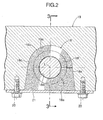
- Tubular stabilizer bushes 18 and 18 made of rubber are fitted onto opposite ends of the torsion portion 15 adjacent to the left and right curved portions 17 and 17, and these stabilizer bushes 18 and 18 are supported by being clamped between a U-shaped mounting portion 19a (see FIG. 2 ) of a vehicle body 19 and a plate-shaped mounting bracket 21 fixed by bolts 20 and 20 to the vehicle body 19 so as to cover the mounting portion 19a.
- each stabilizer bush 18 includes a flat first outer peripheral face 18a, a U-shaped second outer peripheral face 18b, a pair of side faces 18c and 18c, and a circular cross-section inner peripheral face 18d opening on the two side faces 18c and 18c and into which the torsion portion 15 of the stabilizer 14 is fitted.
- a split groove-shaped slit 18e is formed in the stabilizer bush 18, the slit 18e being disposed within a plane containing an axis L of the stabilizer bush 18 and extending from the second outer peripheral face 18b to the inner peripheral face 18d.
- chamfered portions 18f and 18f opening out radially outwardly are formed at opposite ends, along the axis L direction, of the inner peripheral face 18d.
- the stabilizer bush 18 having the above-mentioned shape may be fitted onto the outer peripheral face of the torsion portion 15 of the stabilizer 14 by resiliently deforming the slit 18e so as to widen it.
- the U-shaped second outer peripheral face 18b of the stabilizer bush 18 is fitted into the U-shaped mounting portion 19a of the vehicle body 19, and the flat first outer peripheral face 18a is retained by abutting it against the flat mounting bracket 21.
- the stabilizer bush 18 is clamped between the vehicle body 19 and the mounting bracket 21 and compressed radially inwardly by a predetermined tightening allowance, the inner peripheral face 18d is pressed against the outer peripheral face of the torsion portion 15 of the stabilizer 14, and the slit 18e is pressed so as to close it.
- the stabilizer 14 having the above arrangement, when the left and right wheels W and W move vertically with the same phase, since the left and right arm portions 16 and 16 move vertically with the same phase, the torsion portion 15 is not twisted, and a roll moment is not generated, but when the left and right wheels W and W move vertically with opposite phases, since the left and right arm portions 16 and 16 move vertically with opposite phases, the torsion portion 15 is twisted, and a roll moment for suppressing rolling of the vehicle body is thus generated, thereby enhancing the drivability of the vehicle.
- the chamfered portions 18f and 18f formed at opposite ends, in the axis L direction, of the inner peripheral face 18d of the stabilizer bush 18 function so as to prevent sand or mud from entering.
- the stabilizer bush 18 when the stabilizer bush 18 is clamped between the vehicle body 19 and the mounting bracket 21 and compressed radially inwardly by a predetermined tightening allowance, the stabilizer bush 18 resiliently deforms so as to be pushed outward in the axis L direction, an end part in the axis-L direction of the inner peripheral face 18d turns up, thus forming a gap across the outer peripheral face of the torsion portion 15, and there is a possibility of sand or mud entering through the gap.
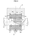
- the chamfered portions 18f and 18f are provided at the ends, in the axis L direction, of the inner peripheral face 18d of the stabilizer bush 18, when a compressive load A is applied thereto in a direction perpendicular to the axis L in FIG. 3 , a load B facing inward in the axis L direction is generated, thus increasing the surface pressure with which a part a of the open end of the inner peripheral face 18d contacts the torsion portion 15.
- a radial load is applied to the torsion portion 15
- the stabilizer bush 18 does not have a thin lip, the durability improves.
- the function of preventing sand or mud from entering, exhibited by the chamfered portions 18f and 18f, is changed by the size of an acute angle ⁇ formed by the axis L of the stabilizer bush 18 and the chamfered portions 18f and 18f.
- FIG. 4A and FIG. 4B show cases in which the acute angle ⁇ is 65° and 35°.
- the reaction force F2' which works so as to push open the chamfered portion 18f
- the reaction force F2' which works so as to push open the chamfered portion 18f
- the acute angle ⁇ is large, it is harder for a foreign body to bite into the chamfered portion 18f, and it is easier to eject a foreign body once it has bitten into the chamfered portion 18f instead of it remaining there.
- a lower limit value of the acute angle ⁇ is 45°.
- an upper limit of the acute angle ⁇ is 75°. It is therefore possible, by setting the acute angle ⁇ in the range of 45° to 75°, to prevent a foreign body from biting into the chamfered portion 18f or prevent it being difficult to eject a foreign body that has bitten in, while making it difficult to open the open end of the inner peripheral face 18d of the stabilizer bush 18.
- FIG. 5 A second embodiment of the present invention is now explained by reference to FIG. 5 .
- small-diameter portions 18g and 18g having a reduced inner diameter are formed at opposite ends, in the axis L direction, of the inner peripheral face 18d of the stabilizer bush 18 of the first embodiment, that is, they are portions connected to the chamfered portions 18f and 18f. Due to the small-diameter portions 18g and 18g being formed, the surface pressure with which the inner peripheral face 18d of the stabilizer bush 18 abuts against the outer peripheral face of the torsion portion 15 increases, thus more reliably preventing sand or mud from entering.
- FIG. 6 A third embodiment of the present invention is now explained by reference to FIG. 6 , FIG. 7A, and FIG. 7B .
- the slit 18e of the stabilizer bush 18 of the first and second embodiments is formed by cutting with a cutter or a laser after molding the stabilizer bush 18, but in a stabilizer bush 18 of the third embodiment its slit 18e is formed by the combined use of die molding and cutting.
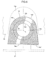
- a first bulge portion 18a' projects radially outward from a first outer peripheral face 18a on the slit 18e side
- a second bulge portion 18b' projects radially outward from a second outer peripheral face 18b on the slit 18e side. Therefore, when the stabilizer bush 18 is held between a mounting portion 19a of a vehicle body 19 and a mounting bracket 21, by compressing the first and second bulge portions 18a' and 18b' the slit 18e closes up tight, thus preventing sand or mud from entering therethrough.
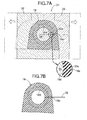
- a die 31 for molding the stabilizer bush 18 is formed from a first die 32, a second die 33, and a core 34, and a wedge-shaped projection 33a for molding the slit 18e is formed on the second die 33.
- the extremity of the wedge-shaped projection 33a does not reach the outer peripheral face of the core 34 and, therefore, when it is molded by means of the die 31, the extremity of the slit 18e of the stabilizer bush 18 does not communicate with an inner peripheral face 18d.
- the extremity of the slit 18e is cut completely up to the inner peripheral face 18d by means of a cutter 35 (or a laser).
- the slit 18e were formed only by die molding so as to reach the inner peripheral face 18d, flashing would unavoidably be formed between the projection 33a of the second die 33 and the core 34; the flashing would not allow the slit 18e to close completely, and a gap might be formed, but by cutting the extremity of the slit 18e using the cutter 35, the intimacy of contact of this portion can be enhanced, thus preventing a foreign body from entering.
- FIG. 8A and FIG. 8B A fourth embodiment of the present invention is now explained by reference to FIG. 8A and FIG. 8B .
- the chamfered portions 18f and 18f which open out radially outwardly, are formed over 360° at opposite ends, in the axis L direction, of the inner peripheral face 18d of the stabilizer bush 18, but in the fourth embodiment chamfered portions 18f and 18f are formed only in opposite side portions sandwiching a slit 18e.
- the shape of the chamfered portion 18f when viewed in the axis L direction is tapered in an isosceles triangle shape radially outwardly from an inner peripheral face 18d of a stabilizer bush 18, and the vertex thereof is positioned on the slit 18e.
- the depth of the chamfered portion 18f is the deepest at a position where the slit 18e intersects the inner peripheral face 18d of the stabilizer bush 18, and gradually becomes shallower in going radially outward therefrom and also toward opposite sides in the circumferential direction.
- the operation of the chamfered portion 18f of the fourth embodiment is the same as that of the annular chamfered portion 18f of the first embodiment, but by providing the chamfered portion 18f on opposite sides of the slit 18e, which is easily opened out by a radial load accompanying twisting deformation of the stabilizer 14 to thus allow sand or mud to enter, it is possible to attain the same operational effects as those of the chamfered portion 18f extending over 360° of the first to third embodiments, while reducing the dimensions of the chamfered portion 18f.
- FIG. 9A and FIG. 9B A fifth embodiment of the present invention is now explained by reference to FIG. 9A and FIG. 9B .
- the chamfered portion 18f of the fourth embodiment is formed in an isosceles triangle shape, but a chamfered portion 18f of the fifth embodiment is formed in a crescent shape, the arrangement otherwise being the same.
- the function of preventing sand or mud from entering via the slit 18e is the same for the fourth embodiment and the fifth embodiment, but the fifth embodiment has the effect of improving the workability during production.
- the slit 18e is machined by means of a cutter 35 (or a laser).
- a cutter 35 or a laser.
- FIG. 10A if as in the fourth embodiment an isosceles triangle-shaped chamfered portion 18f is provided, when the position of the slit 18e is off only slightly, in the circumferential direction, it misses the vertex of the isosceles triangle-shaped chamfered portion 18f, and the function of the chamfered portion 18f might be impaired.
- FIG. 10A if as in the fourth embodiment an isosceles triangle-shaped chamfered portion 18f is provided, when the position of the slit 18e is off only slightly, in the circumferential direction, it misses the vertex of the isosceles triangle-shaped chamfered portion 18f, and the function of the chamfered portion 18f might be impaired.
- FIG. 10A if as in the fourth embodiment an isosceles triangle-shaped chamfered portion 18f is provided
- the stabilizer bush 18 has a linear chamfered portion 18f, but it is not always necessary for the chamfered portion 18f to be linear.
- a chamfered portion 18f is curved
- a chamfered portion 18f has a stepped linear shape.
- FIG. 12 to FIG. 16 An eighth embodiment of the present invention is now explained by reference to FIG. 12 to FIG. 16 .
- strut type suspension systems S and S suspending left and right wheels W and W include left and right knuckles 11 and 11 vertically movably supported on a vehicle body via suspension arms 10 and 10, dampers 12 and 12 connected to upper parts of the knuckles 11 and 11 and extending upward, suspension springs 13 and 13 disposed coaxially on the outer periphery of upper parts of the dampers 12 and 12, and a stabilizer 14 providing a connection between the upper parts of the left and right knuckles 11 and 11.
- the stabilizer 14 includes a torsion portion 15 extending linearly in the vehicle width direction, left and right arm portions 16 and 16 extending linearly from opposite ends of the torsion portion 15 toward the rear of the vehicle body, and left and right curved portions 17 and 17 providing smooth connections between the torsion portion 15 and the arm portions 16 and 16. Extremities of the left and right arm portions 16 and 16 are connected to the dampers 12 and 12 via links 22 and 22.
- Tubular stabilizer bushes 18 and 18 made of rubber are fitted onto opposite ends of the torsion portion 15 adjacent to the left and right curved portions 17 and 17, and these stabilizer bushes 18 and 18 are supported by being clamped between a U-shaped mounting portion 19a (see FIG. 13 ) of a vehicle body 19 and a plate-shaped mounting bracket 21 fixed by bolts 20 and 20 to the vehicle body 19 so as to cover the mounting portion 19a.
- each stabilizer bush 18 includes a flat first outer peripheral face 18a, a U-shaped second outer peripheral face 18b, a pair of side faces 18c and 18c, and a circular cross-section inner peripheral face 18d opening on the two side faces 18c and 18c and into which the torsion portion 15 of the stabilizer 14 is fitted.
- a split groove-shaped slit 18e is formed in the stabilizer bush 18, the slit 18e being disposed within a plane containing an axis L of the stabilizer bush 18 and extending from the second outer peripheral face 18b to the inner peripheral face 18d, and small-diameter portions 18g and 18g projecting radially inwardly are formed at the open end of the inner peripheral face 18d.
- a pair of thick portions 18h and 18h project in the axis L direction at positions, sandwiching the slit 18e, on each side face 18c.
- the thick portions 18h and 18h are slightly spaced from the slit 18e and extend radially with the axis L as the center.
- the stabilizer bush 18 having the above-mentioned shape may be fitted onto the outer peripheral face of the torsion portion 15 of the stabilizer 14 by resiliently deforming the slit 18e so as to widen it.
- the U-shaped second outer peripheral face 18b of the stabilizer bush 18 is fitted into the U-shaped mounting portion 19a of the vehicle body 19, and the flat first outer peripheral face 18a is abutted against and retained by the flat mounting bracket 21.
- the stabilizer 14 having the above arrangement, when the left and right wheels W and W move vertically with the same phase, since the left and right arm portions 16 and 16 move vertically with the same phase, the torsion portion 15 is not twisted, and a roll moment is not generated, but when the left and right wheels W and W move vertically with opposite phases, since the left and right arm portions 16 and 16 move vertically with opposite phases, the torsion portion 15 is twisted, and a roll moment for suppressing rolling of the vehicle body is thus generated, thereby enhancing the drivability of the vehicle.
- the slit 18e of the stabilizer bush 18 opens and allows sand or mud to enter between the outer peripheral face of the torsion portion 15 and the inner peripheral face 18d of the stabilizer bush 18, thus generating abnormal noise or causing abrasion of the torsion portion 15, which is a problem.
- the rigidity of the stabilizer bush 18 against radial compression is higher for sections with the thick portions 18h and 18h than for a section without them.
- the slit 18e is pushed from opposite sides by the thick portions 18h and 18h having high rigidity and strongly compressed in a closing direction, and it becomes harder to open even when a radial external force acts on the torsion portion 15, thus reliably preventing sand or mud from entering between the outer peripheral face of the torsion portion 15 and the inner peripheral face 18d of the stabilizer bush 18 via the slit 18e.
- the small-diameter portions 18g and 18g which are formed at the open end of the inner peripheral face 18d of the stabilizer bush 18, are strongly pressed against the outer peripheral face of the torsion portion 15, thus more reliably preventing sand or mud from entering through the open end and reaching the outer peripheral face of the torsion portion 15.
- a ninth embodiment of the present invention is now explained by reference to FIG. 17 .
- the slit 18e of the stabilizer bush 18 is closed in a free state, but a slit 18e of the ninth embodiment opens in a wedge shape from a second outer peripheral face 18b to an inner peripheral face 18d in a free state, and edges of two thick portions 18h and 18h formed on respective side faces 18c coincide with edges of the slit 18e.
- a first bulge portion 18a' projects radially outward from a first outer peripheral face 18a on the slit 18e side and a second bulge portion 18b' projects radially outward from the second outer peripheral face 18b on the slit 18e side.
- the first and second bulge portions 18a' and 18b' are compressed so as to close up tight the slit 18e.
- the thick portions 18h and 18h function so as to firmly close the slit 18e, thereby reliably preventing sand or mud from entering.
- the slit 18e of the stabilizer bush 18 of the eighth embodiment is formed by cutting with a cutter or a laser after molding the stabilizer bush 18, but in the stabilizer bush 18 of the ninth embodiment its slit 18e is formed by the combined use of die molding and cutting. This technique is the same as that explained for FIG. 7A and FIG. 7B above, and duplication of the explanation is omitted.
- the stabilizer 14 of the embodiments integrally includes the torsion portion 15, the arm portions 16 and 16, and the curved portions 17 and 17, but arm portions 16 and 16 may be formed from a separate member and fixed to opposite ends of a linear torsion portion 15 via a bolt, etc.
- the strut type suspension S is illustrated, but the stabilizer 14 of the present invention may be applied to any type of suspension system.
- the stabilizer bush 18 is supported by being clamped between the U-shaped mounting portion 19a formed on the vehicle body 19 and the flat mounting bracket 21, but the stabilizer bush 18 may be supported on a flat face of the vehicle body 19 using a U-shaped mounting bracket.
- the arm portions 16 and 16 of the stabilizer 14 are connected to the dampers 12 and 12, but the arm portions 16 and 16 of the stabilizer 14 may be connected to the knuckles 11 and 11 or the suspension arms 10 and 10.
- the thick portions 18h and 18h are formed by making portions, on opposite sides of the slit 18e, of the side face 18c of the stabilizer bush 18 project in the axis L direction, but it is not always necessary for the thick portions 18h and 18h to project from the side face 18c in the axis L direction as long as the thick portions 18h and 18h are thicker in the axis L direction than the other portions of the side face 18c.
- a stabilizer bush (18) is fitted onto the outer peripheral face of a torsion portion (15) of a stabilizer and fixed by being clamped under pressure between a mounting portion (19a) of a vehicle body (19) and a mounting bracket (21). Since a chamfered portion (18f) that opens out radially outwardly is formed at an open end of an inner peripheral face (18d) of the stabilizer bush (18), when the stabilizer bush (18) is compressed radially inwardly, a load that is inward in an axis (L) direction is generated at the open end, thus preventing the open end from opening in a way such that it turns up.
Landscapes
- Engineering & Computer Science (AREA)
- Mechanical Engineering (AREA)
- Vehicle Body Suspensions (AREA)
- Springs (AREA)
Abstract
Description
- The present invention relates to a stabilizer support structure in which an inner peripheral face of a tubular stabilizer bush is fitted onto an outer peripheral face of a torsion portion of a stabilizer providing a connection between left and right suspension systems, and an outer peripheral face of the stabilizer bush is clamped under pressure and fixed between a mounting portion of a vehicle body and a fixing member fixed to the vehicle body.
- An arrangement is known from
Patent Publication 1 below in which an axial hole of a rubber stabilizer bush is fitted onto the outer periphery of a torsion portion of a stabilizer providing a connection between left and right suspension systems, and the stabilizer bush is supported on a vehicle body frame via a mounting bracket, wherein forming a rib (lip) at an open end of the axial hole of the stabilizer bush prevents sand or mud from entering between sliding faces of the stabilizer bush and the stabilizer. - Patent Publication 1: Japanese Utility Model Registration Application Laid-open No.
4-11710 - In the above conventional arrangement, since the open end of the axial hole of the stabilizer bush is equipped with a thin lip, when the lip of the stabilizer bush slides against the outer peripheral face of the torsion portion of the stabilizer over a long period of time, the lip might be abraded or broken, and it might become impossible to prevent sand or mud from entering.
- In particular, when, in order to fit the stabilizer bush onto the outer peripheral face of the torsion portion of the stabilizer, the stabilizer bush is equipped with a slit that is cut from the outer peripheral face to the inner peripheral face along the axis, if a load in the radial direction is imposed on the torsion portion, the slit opens, and sand or mud that has entered through the opened slit might reach the outer peripheral face of the torsion portion.
- The present invention has been accomplished in the light of the above-mentioned circumstances, and it is an object thereof to prevent, by a simple and highly durable structure, sand or mud from entering between an outer peripheral face of a stabilizer and an inner peripheral face of a stabilizer bush.
- In order to attain the above object, according to a first aspect of the present invention, there is provided a stabilizer support structure in which an inner peripheral face of a tubular stabilizer bush is fitted onto an outer peripheral face of a torsion portion of a stabilizer providing a connection between left and right suspension systems, and an outer peripheral face of the stabilizer bush is clamped under pressure and fixed between a mounting portion of a vehicle body and a fixing member fixed to the vehicle body, characterized in that a chamfered portion opening out radially outwardly is formed on at least one open end of the inner peripheral face of the stabilizer bush.
- According to a second aspect of the present invention, in addition to the first aspect, an acute angle formed by an axis of the stabilizer bush and the chamfered portion is 45° to 75°.
- According to a third aspect of the present invention, in addition to the first aspect, the stabilizer bush comprises a slit cut from the outer peripheral face to the inner peripheral face along the axis, and the width of the slit decreases in a wedge shape from the outer peripheral face side to the inner peripheral face side.
- According to a fourth aspect of the present invention, in addition to the third aspect, the slit is formed by die-molding for the outer peripheral face side and by cutting by means of a cutter or a laser for the inner peripheral face side.
- According to a fifth aspect of the present invention, in addition to the first aspect, a small-diameter portion projecting radially inwardly is provided on an edge portion of the chamfered portion on the inner peripheral face side.
- According to a sixth aspect of the present invention, in addition to the first aspect, the stabilizer comprises arm portions extending linearly in the longitudinal direction of the vehicle body from opposite ends of the torsion portion extending linearly in the vehicle width direction, wherein the arm portion is formed from a member separate from the torsion portion, and end parts on the front side in the longitudinal direction of the vehicle body are mounted on opposite ends of the torsion portion.
- According to a seventh aspect of the present invention, in addition to the first aspect, in a cross section of the stabilizer bush perpendicular to an axis thereof, the chamfered portion is formed in a linear shape.
- According to an eighth aspect of the present invention, in addition to the first aspect, in a cross section of the stabilizer bush perpendicular to an axis thereof, the chamfered portion is formed in a curved shape.
- According to a ninth aspect of the present invention, in addition to the first aspect, in a cross section of the stabilizer bush containing to an axis thereof, the chamfered portion is formed in a stepped linear shape.
- According to a tenth aspect of the present invention, in addition to the third aspect, a thick portion extending radially along opposite sides of the slit is provided on a side face, in the axis direction, of the stabilizer bush.
- According to an eleventh aspect of the present invention, there is provided a stabilizer support structure in which an inner peripheral face of a tubular stabilizer bush is fitted onto an outer peripheral face of a torsion portion of a stabilizer providing a connection between left and right suspension systems, and an outer peripheral face of the stabilizer bush is clamped under pressure and fixed between a mounting portion of a vehicle body and a fixing member fixed to the vehicle body, characterized in that the stabilizer bush comprises a slit cut from the outer peripheral face to the inner peripheral face along an axis, and a chamfered portion opening out radially outwardly is formed on at least one open end of the inner peripheral face of the stabilizer bush at least in positions sandwiching the slit.
- In the 11th aspect above, the chamfered portion may be provided on the entire periphery of the open end of the inner peripheral face of the stabilizer bush or may be provided only at positions sandwiching the slit.
- According to a twelfth aspect of the present invention, there is provided a stabilizer support structure in which a tubular stabilizer bush fitted onto an outer peripheral face of a torsion portion of a stabilizer providing a connection between left and right suspension systems comprises a slit cut from an outer peripheral face to an inner peripheral face thereof along an axis, and the stabilizer bush is clamped under pressure and fixed between a mounting portion of a vehicle body and a fixing member fixed to the vehicle body, characterized in that a thick portion extending radially along opposite sides of the slit is provided on a side face of the stabilizer bush in the axis direction.
- According to a thirteenth aspect of the present invention, in addition to the twelfth aspect, a chamfered portion opening out radially outwards is formed on at least one open end of the inner peripheral face of the stabilizer bush.
- According to a fourteenth aspect of the present invention, in addition to the first aspect, the stabilizer bush comprises: a first outer peripheral face abutting against the fixing member, a second outer peripheral face abutting against the mounting portion of the vehicle body, a first bulge portion projecting radially outward from the first outer peripheral face, and a second bulge portion projecting radially outward from the second outer peripheral face.
- According to a fifteenth aspect of the present invention, in addition to the eleventh aspect, the stabilizer bush comprises: a first outer peripheral face abutting against the fixing member, a second outer peripheral face abutting against the mounting portion of the vehicle body, a first bulge portion projecting radially outward from the first outer peripheral face, and a second bulge portion projecting radially outward from the second outer peripheral face.
- First and second outer
peripheral faces mounting bracket 21 of the embodiment corresponds to the fixing member of the present invention. - In accordance with the first aspect of the present invention, the stabilizer bush is fitted onto the outer peripheral face of the torsion portion of the stabilizer and fixed by being clamped under pressure between the mounting portion of the vehicle body and the fixing member. Since a chamfered portion that opens out radially outwardly is formed at the open end of the inner peripheral face of the stabilizer bush, when the stabilizer bush is compressed radially inwardly by being clamped under pressure between the mounting portion of the vehicle body and the fixing member, an axially inward load is generated at the open end of the inner peripheral face, thus preventing the open end from opening in a way such that it turns up. It is thereby possible to prevent sand or mud from entering between the inner peripheral face of the stabilizer bush and the torsion portion of the stabilizer, thus preventing the' occurrence of abnormal noise or abrasion of the stabilizer. Moreover, since the stabilizer bush does not have a thin lip, its durability is improved.
- Furthermore, in accordance with the second aspect of the present invention, since the acute angle formed by the axis of the stabilizer bush and the chamfered portion is set at 45° to 75°, when a foreign body is pressed against the chamfered portion of the stabilizer bush, the open end of the inner peripheral face is difficult to open, and a foreign body held by the chamfered portion is prevented from biting thereinto and can be easily ejected.
- Moreover, in accordance with the third aspect of the present invention, since the width of the slit that is cut along the axis of the stabilizer bush decreases in a wedge shape from the outer peripheral face side to the inner peripheral face side, when the slit is closed by clamping under pressure and fixing the stabilizer bush between the mounting portion of the vehicle body and the fixing member, a strong contact surface pressure is generated in an extremity portion of the slit communicating with the inner peripheral face, thus preventing a gap from being formed and preventing a foreign body from entering through the slit.
- Furthermore, in accordance with the fourth aspect of the present invention, since the outer peripheral face side of the slit of the stabilizer bush is formed by molding with a die and the inner peripheral face side is formed by cutting with a cutter or a laser, it is possible to prevent flashing from being formed in the portion via which the slit communicates with the inner peripheral face, thereby enabling the slit to be completely closed up.
- Moreover, in accordance with the fifth aspect of the present invention, since the small-diameter portion is provided so as to project radially inwardly on the edge portion of the inner peripheral face side of the chamfered portion of the stabilizer bush, the surface pressure of the inner peripheral face of the stabilizer bush abutting against the outer peripheral face of the torsion portion increases in the small-diameter portion, thus more reliably preventing the entrance of sand or mud.
- Furthermore, in accordance with the sixth aspect of the present invention, since the stabilizer includes the arm portions linearly extending in the longitudinal direction of the vehicle body from opposite ends of the torsion portion linearly extending in the vehicle width direction, the arm portions are formed from members separate from the torsion portion, and end parts on the front side in the longitudinal direction of the vehicle body are mounted on opposite ends of the torsion portion, compared with a case in which the stabilizer is formed from one member, the degrees of freedom in design can be increased.
- Moreover, in accordance with the seventh aspect of the present invention, since the chamfered portion is formed in a linear shape in the cross section perpendicular to the axis of the stabilizer bush, it is possible to prevent sand or mud from entering between the inner peripheral face of the stabilizer bush and the torsion portion of the stabilizer, thus preventing the occurrence of abnormal noise or abrasion of the stabilizer.
- Furthermore, in accordance with the eighth aspect of the present invention, since the chamfered portion is formed in a curved shape in the cross section perpendicular to the axis of the stabilizer bush, it is possible to prevent sand or mud from entering between the inner peripheral face of the stabilizer bush and the torsion portion of the stabilizer, thus preventing the occurrence of abnormal noise or abrasion of the stabilizer.
- Moreover, in accordance with the ninth aspect of the present invention, since the chamfered portion is formed in a stepped linear shape in the cross section containing the axis of the stabilizer bush, it is possible to prevent sand or mud from entering between the inner peripheral face of the stabilizer bush and the torsion portion of the stabilizer, thus preventing the occurrence of abnormal noise or abrasion of the stabilizer.
- Furthermore, in accordance with the tenth aspect of the present invention, since the rigidity of the thick portion is higher than that of other portions, the thick portion being provided so as to extend in the radial direction along opposite sides of the slit on the side face, in the axis direction, of the stabilizer bush, it is possible to strongly press the slit into contact in a closing direction. It is thereby possible to prevent the slit from opening and sand or mud from entering between the inner peripheral face of the stabilizer bush and the torsion portion of the stabilizer, thus preventing the occurrence of abnormal noise or abrasion of the stabilizer.
- Moreover, in accordance with the eleventh aspect of the present invention, the stabilizer bush is fitted onto the outer peripheral face of the torsion portion of the stabilizer and fixed by being clamped under pressure between the mounting portion of the vehicle body and the fixing member. Since the stabilizer bush includes the slit that is cut along its axis, and the chamfered portion opening out radially outwardly is formed at least at positions, sandwiching the slit, at the open end of the inner peripheral face of the stabilizer bush, when the stabilizer bush is compressed radially inwardly by being clamped under pressure between the mounting portion of the vehicle body and the fixing member, an axially inward load is generated at the positions, sandwiching the slit, at the open end of the inner peripheral face of the stabilizer bush, thus preventing the open end from opening in a way such that it turns up. It is thereby possible to prevent sand or mud from entering between the inner peripheral face of the stabilizer bush and the torsion portion of the stabilizer, thus preventing the occurrence of abnormal noise or abrasion of the stabilizer. Moreover, since the stabilizer bush does not have a thin lip, the durability improves.
- Furthermore, in accordance with the twelfth aspect of the present invention, since, when fixing the stabilizer bush fitted onto the outer peripheral face of the torsion portion of the stabilizer by clamping it under pressure between the mounting portion of the vehicle body and the fixing member fixed to the vehicle body, the thick portions are provided on the side face of the stabilizer bush so as to sandwich the slit, the rigidity of the thick portions is higher than that of other portions, and the slit can be strongly pressed into contact in a closing direction. It is thereby possible to prevent the slit from opening and sand or mud from entering between the inner peripheral face of the stabilizer bush and the torsion portion of the stabilizer, thus preventing the occurrence of abnormal noise or abrasion of the stabilizer.
- Moreover, in accordance with the thirteenth aspect of the present invention, since the chamfered portion opening out radially outwardly is formed on at least one open end of the inner peripheral face of the stabilizer bush, when the stabilizer bush is compressed radially inwardly by being clamped under pressure between the mounting portion of the vehicle body and the fixing member, it is possible to generate an axially inward load at the open end of the inner peripheral face, thereby preventing the open end from opening in a way such that it turns up. It is thereby possible to prevent sand or mud from entering between the inner peripheral face of the stabilizer bush and the torsion portion of the stabilizer, thus preventing the occurrence of abnormal noise or abrasion of the stabilizer. Moreover, since the stabilizer bush does not have a thin lip, the durability improves.
- Furthermore, in accordance with the fourteenth aspect of the present invention, since the first bulge portion is provided so as to project radially outwardly from the first outer peripheral face via which the stabilizer bush abuts against the fixing member, and the second bulge portion is provided so as to project radially outwardly from the second outer peripheral face via which the stabilizer bush abuts against the mounting portion of the vehicle body, when the stabilizer bush is sandwiched by the fixing member and the mounting portion of the vehicle body, the first and second bulge portions are compressed, thus enabling the slit to be strongly tightened.
- Moreover, in accordance with the fifteenth aspect of the present invention, since the first bulge portion is provided so as to project radially outwardly from the first outer peripheral face via which the stabilizer bush abuts against the fixing member, and the second bulge portion is provided so as to project radially outwardly from the second outer peripheral face via which the stabilizer bush abuts against the mounting portion of the vehicle body, when the stabilizer bush is sandwiched by the fixing member and the mounting portion of the vehicle body, the first and second bulge portions are compressed, thus enabling the slit to be strongly tightened.
-
- [FIG. 1]
- A perspective view showing a state in which a stabilizer is mounted on a vehicle
- [FIG. 2]
- An enlarged sectional view along line 2-2 in
FIG. 1 - [FIG. 3]
- A sectional view along line 3-3 in
FIG. 2 - [FIG. 4A]
- A diagram for explaining the operation of a chamfered portion of a stabilizer bush
- [FIG. 4B]
- A diagram for explaining the operation of a chamfered portion of a stabilizer bush
- [FIG. 5]
- A vertical sectional view of a stabilizer bush
- [FIG. 6]
- A side view of a stabilizer bush
- [FIG. 7A]
- A diagram for explaining a process for producing a stabilizer bush
- [FIG. 7B]
- A diagram for explaining the process for producing a stabilizer bush
- [FIG. 8A]
- A diagram showing a stabilizer bush
- [FIG. 8B]
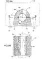
- A sectional view along line B-B in
FIG. 8A - [FIG. 9A]
- A diagram showing a stabilizer bush
- [FIG. 9B]
- A sectional view along line B-B in
FIG. 9A - [FIG. 10A]
- A diagram for explaining the operation when machining a slit
- [FIG. 10B]
- A diagram for explaining the operation when machining a slit
- [FIG. 11A]
- A vertical sectional view of a stabilizer bush
- [FIG. 11 B]
- A vertical sectional view of a stabilizer bush
- [FIG. 12]
- A perspective view showing a state in which a stabilizer is mounted on a vehicle
- [FIG. 13]
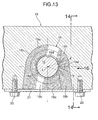
- An enlarged view from arrowed line 13-13 in
FIG: 12 - [FIG. 14]
- A sectional view along line 14-14 in
FIG. 13 - [FIG. 15]
- A sectional view, corresponding to
FIG. 14 , of a stabilizer bush in a free state - [FIG. 16]
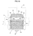
- A view from the direction of
arrow 16 inFIG. 13 - [FIG. 17]
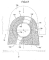
- A side view of a stabilizer bush in a free state
-
- 14
- Stabilizer
- 15
- Torsion portion
- 18
- Stabilizer bush
- 18a
- First outer peripheral face (outer peripheral face)
- 18b
- Second outer peripheral face (outer peripheral face)
- 18d
- Inner peripheral face
- 18e
- Slit
- 18f
- Chamfered portion
- 18g
- Small-diameter portion
- 18h
- Thick portion
- 19
- Vehicle body
- 19a
- Mounting portion
- 21
- Mounting bracket (fixing member)
- 35
- Cutter
- L
- Axis
- S
- Suspension system
- A first embodiment of the present invention is now explained by reference to
FIG. 1 to FIG. 4B . - As shown in
FIG. 1 , strut type suspension systems S and S. suspending left and right wheels W and W include left andright knuckles suspension arms dampers knuckles dampers stabilizer 14 providing a connection between the upper parts of the left andright knuckles - The
stabilizer 14 includes atorsion portion 15 extending linearly in the vehicle width direction, left andright arm portions torsion portion 15 toward the rear of the vehicle body, and left and rightcurved portions torsion portion 15 and thearm portions right arm portions dampers links Tubular stabilizer bushes torsion portion 15 adjacent to the left and rightcurved portions stabilizer bushes portion 19a (seeFIG. 2 ) of avehicle body 19 and a plate-shaped mountingbracket 21 fixed bybolts vehicle body 19 so as to cover the mountingportion 19a. - As is clear from
FIG. 2 andFIG. 3 , eachstabilizer bush 18 includes a flat first outerperipheral face 18a, a U-shaped second outerperipheral face 18b, a pair of side faces 18c and 18c, and a circular cross-section innerperipheral face 18d opening on the two side faces 18c and 18c and into which thetorsion portion 15 of thestabilizer 14 is fitted. A split groove-shapedslit 18e is formed in thestabilizer bush 18, theslit 18e being disposed within a plane containing an axis L of thestabilizer bush 18 and extending from the second outerperipheral face 18b to the innerperipheral face 18d. Furthermore, chamferedportions peripheral face 18d. - The
stabilizer bush 18 having the above-mentioned shape may be fitted onto the outer peripheral face of thetorsion portion 15 of thestabilizer 14 by resiliently deforming theslit 18e so as to widen it. The U-shaped second outerperipheral face 18b of thestabilizer bush 18 is fitted into the U-shaped mountingportion 19a of thevehicle body 19, and the flat first outerperipheral face 18a is retained by abutting it against theflat mounting bracket 21. In this arrangement, thestabilizer bush 18 is clamped between thevehicle body 19 and the mountingbracket 21 and compressed radially inwardly by a predetermined tightening allowance, the innerperipheral face 18d is pressed against the outer peripheral face of thetorsion portion 15 of thestabilizer 14, and theslit 18e is pressed so as to close it. - With regard to the
stabilizer 14 having the above arrangement, when the left and right wheels W and W move vertically with the same phase, since the left andright arm portions torsion portion 15 is not twisted, and a roll moment is not generated, but when the left and right wheels W and W move vertically with opposite phases, since the left andright arm portions torsion portion 15 is twisted, and a roll moment for suppressing rolling of the vehicle body is thus generated, thereby enhancing the drivability of the vehicle. - When an external force acts on the
stabilizer 14 in the radial direction, a gap is formed between the outer peripheral face of thetorsion portion 15 and the innerperipheral face 18d of thestabilizer bush 18, and there is a possibility of sand or mud entering therethrough, thus causing abnormal noise or abrasion. In this embodiment, thechamfered portions peripheral face 18d of thestabilizer bush 18 function so as to prevent sand or mud from entering. - That is, when the
stabilizer bush 18 is clamped between thevehicle body 19 and the mountingbracket 21 and compressed radially inwardly by a predetermined tightening allowance, thestabilizer bush 18 resiliently deforms so as to be pushed outward in the axis L direction, an end part in the axis-L direction of the innerperipheral face 18d turns up, thus forming a gap across the outer peripheral face of thetorsion portion 15, and there is a possibility of sand or mud entering through the gap. - However, since the
chamfered portions peripheral face 18d of thestabilizer bush 18, when a compressive load A is applied thereto in a direction perpendicular to the axis L inFIG. 3 , a load B facing inward in the axis L direction is generated, thus increasing the surface pressure with which a part a of the open end of the innerperipheral face 18d contacts thetorsion portion 15. As a result, even when a radial load is applied to thetorsion portion 15, it is possible to prevent a gap from being formed between the outer peripheral face thereof and the innerperipheral face 18d of thestabilizer bush 18, thus preventing sand or mud from entering. Moreover, since thestabilizer bush 18 does not have a thin lip, the durability improves. - The function of preventing sand or mud from entering, exhibited by the chamfered
portions stabilizer bush 18 and thechamfered portions portion 18f in the axis L direction with a load F, the load F is resolved into a component F1 in a direction perpendicular to the chamferedportion 18f and a component F2 in a direction perpendicular to the axis L, and a reaction force F2' to the component F2 in the direction perpendicular to the axis L works so as to push open the chamferedportion 18f. -
FIG. 4A and FIG. 4B show cases in which the acute angle θ is 65° and 35°. In the case ofFIG. 4A in which the acute angle θ is large, the reaction force F2', which works so as to push open the chamferedportion 18f, is small, but in the case ofFIG. 4B in which the acute angle θ is small, the reaction force F2', which works so as to push open the chamferedportion 18f, is large. When the acute angle θ is large, it is harder for a foreign body to bite into the chamferedportion 18f, and it is easier to eject a foreign body once it has bitten into the chamferedportion 18f instead of it remaining there. For these reasons it is desirable that a lower limit value of the acute angle θ is 45°. - On the other hand, as described above, when the acute angle θ is close to a right angle, since the chamfered
portion 18f is pushed outward in the axis L direction and opens in a way such that it turns up due to the load that works to compress thestabilizer bush 18 radially inwardly, it is desirable that an upper limit of the acute angle θ is 75°. It is therefore possible, by setting the acute angle θ in the range of 45° to 75°, to prevent a foreign body from biting into the chamferedportion 18f or prevent it being difficult to eject a foreign body that has bitten in, while making it difficult to open the open end of the innerperipheral face 18d of thestabilizer bush 18. - A second embodiment of the present invention is now explained by reference to
FIG. 5 . - In the second embodiment, small-
diameter portions peripheral face 18d of thestabilizer bush 18 of the first embodiment, that is, they are portions connected to thechamfered portions diameter portions peripheral face 18d of thestabilizer bush 18 abuts against the outer peripheral face of thetorsion portion 15 increases, thus more reliably preventing sand or mud from entering. - A third embodiment of the present invention is now explained by reference to
FIG. 6 ,FIG. 7A, and FIG. 7B . - The
slit 18e of thestabilizer bush 18 of the first and second embodiments is formed by cutting with a cutter or a laser after molding thestabilizer bush 18, but in astabilizer bush 18 of the third embodiment itsslit 18e is formed by the combined use of die molding and cutting. - As shown in
FIG. 6 , in thestabilizer bush 18, afirst bulge portion 18a' projects radially outward from a first outerperipheral face 18a on theslit 18e side, and asecond bulge portion 18b' projects radially outward from a second outerperipheral face 18b on theslit 18e side. Therefore, when thestabilizer bush 18 is held between a mountingportion 19a of avehicle body 19 and a mountingbracket 21, by compressing the first andsecond bulge portions 18a' and 18b' theslit 18e closes up tight, thus preventing sand or mud from entering therethrough. - As shown in
FIG. 7A , adie 31 for molding thestabilizer bush 18 is formed from afirst die 32, asecond die 33, and acore 34, and a wedge-shapedprojection 33a for molding theslit 18e is formed on thesecond die 33. The extremity of the wedge-shapedprojection 33a does not reach the outer peripheral face of thecore 34 and, therefore, when it is molded by means of the die 31, the extremity of theslit 18e of thestabilizer bush 18 does not communicate with an innerperipheral face 18d. After molding by means of the die 31 is completed, as shown inFIG. 7B , the extremity of theslit 18e is cut completely up to the innerperipheral face 18d by means of a cutter 35 (or a laser). - If the
slit 18e were formed only by die molding so as to reach the innerperipheral face 18d, flashing would unavoidably be formed between theprojection 33a of thesecond die 33 and thecore 34; the flashing would not allow theslit 18e to close completely, and a gap might be formed, but by cutting the extremity of theslit 18e using thecutter 35, the intimacy of contact of this portion can be enhanced, thus preventing a foreign body from entering. - A fourth embodiment of the present invention is now explained by reference to
FIG. 8A and FIG. 8B . - In the first to third embodiments described above, the
chamfered portions peripheral face 18d of thestabilizer bush 18, but in the fourth embodiment chamferedportions slit 18e. The shape of the chamferedportion 18f when viewed in the axis L direction is tapered in an isosceles triangle shape radially outwardly from an innerperipheral face 18d of astabilizer bush 18, and the vertex thereof is positioned on theslit 18e. Therefore, the depth of the chamferedportion 18f is the deepest at a position where theslit 18e intersects the innerperipheral face 18d of thestabilizer bush 18, and gradually becomes shallower in going radially outward therefrom and also toward opposite sides in the circumferential direction. - The operation of the chamfered
portion 18f of the fourth embodiment is the same as that of the annular chamferedportion 18f of the first embodiment, but by providing the chamferedportion 18f on opposite sides of theslit 18e, which is easily opened out by a radial load accompanying twisting deformation of thestabilizer 14 to thus allow sand or mud to enter, it is possible to attain the same operational effects as those of the chamferedportion 18f extending over 360° of the first to third embodiments, while reducing the dimensions of the chamferedportion 18f. - A fifth embodiment of the present invention is now explained by reference to
FIG. 9A and FIG. 9B . - The chamfered
portion 18f of the fourth embodiment is formed in an isosceles triangle shape, but a chamferedportion 18f of the fifth embodiment is formed in a crescent shape, the arrangement otherwise being the same. The function of preventing sand or mud from entering via theslit 18e is the same for the fourth embodiment and the fifth embodiment, but the fifth embodiment has the effect of improving the workability during production. - That is, as described above, after die-molding a
stabilizer bush 18, theslit 18e is machined by means of a cutter 35 (or a laser). In this process, as shown inFIG. 10A , if as in the fourth embodiment an isosceles triangle-shapedchamfered portion 18f is provided, when the position of theslit 18e is off only slightly, in the circumferential direction, it misses the vertex of the isosceles triangle-shapedchamfered portion 18f, and the function of the chamferedportion 18f might be impaired. On the other hand, as shown inFIG. 10B , when the crescent shaped chamferedportion 18f of the fifth embodiment is provided, even if the position of theslit 18e is slightly off in the circumferential direction, it has hardly any effect, and the function of the chamferedportion 18f can be exhibited stably. - In the first to third embodiments, the
stabilizer bush 18 has a linear chamferedportion 18f, but it is not always necessary for the chamferedportion 18f to be linear. In an example ofFIG. 11A showing a sixth embodiment of the present invention, a chamferedportion 18f is curved, and in an example ofFIG. 11B showing a seventh embodiment of the present invention, a chamferedportion 18f has a stepped linear shape. In these embodiments, in a state in which astabilizer bush 18 is fitted, by setting an acute angle formed by the chamferedportion 18f relative to the axis L in a range of 45° to 75° it is possible to attain the same operational effects as those of the first to third embodiments. - An eighth embodiment of the present invention is now explained by reference to
FIG. 12 to FIG. 16 . - As shown in
FIG. 12 , strut type suspension systems S and S suspending left and right wheels W and W include left andright knuckles suspension arms dampers knuckles dampers stabilizer 14 providing a connection between the upper parts of the left andright knuckles - The
stabilizer 14 includes atorsion portion 15 extending linearly in the vehicle width direction, left andright arm portions torsion portion 15 toward the rear of the vehicle body, and left and rightcurved portions torsion portion 15 and thearm portions right arm portions dampers links Tubular stabilizer bushes torsion portion 15 adjacent to the left and rightcurved portions stabilizer bushes portion 19a (seeFIG. 13 ) of avehicle body 19 and a plate-shaped mountingbracket 21 fixed bybolts vehicle body 19 so as to cover the mountingportion 19a. - As is clear from
FIG. 12 to FIG. 16 , eachstabilizer bush 18 includes a flat first outerperipheral face 18a, a U-shaped second outerperipheral face 18b, a pair of side faces 18c and 18c, and a circular cross-section innerperipheral face 18d opening on the two side faces 18c and 18c and into which thetorsion portion 15 of thestabilizer 14 is fitted. A split groove-shapedslit 18e is formed in thestabilizer bush 18, theslit 18e being disposed within a plane containing an axis L of thestabilizer bush 18 and extending from the second outerperipheral face 18b to the innerperipheral face 18d, and small-diameter portions peripheral face 18d. Furthermore, a pair ofthick portions slit 18e, on eachside face 18c. Thethick portions slit 18e and extend radially with the axis L as the center. - The
stabilizer bush 18 having the above-mentioned shape may be fitted onto the outer peripheral face of thetorsion portion 15 of thestabilizer 14 by resiliently deforming theslit 18e so as to widen it. The U-shaped second outerperipheral face 18b of thestabilizer bush 18 is fitted into the U-shaped mountingportion 19a of thevehicle body 19, and the flat first outerperipheral face 18a is abutted against and retained by theflat mounting bracket 21. - With regard to the
stabilizer 14 having the above arrangement, when the left and right wheels W and W move vertically with the same phase, since the left andright arm portions torsion portion 15 is not twisted, and a roll moment is not generated, but when the left and right wheels W and W move vertically with opposite phases, since the left andright arm portions torsion portion 15 is twisted, and a roll moment for suppressing rolling of the vehicle body is thus generated, thereby enhancing the drivability of the vehicle. - When an external force acts in the radial direction on the
torsion portion 15 of thestabilizer 14, theslit 18e of thestabilizer bush 18 opens and allows sand or mud to enter between the outer peripheral face of thetorsion portion 15 and the innerperipheral face 18d of thestabilizer bush 18, thus generating abnormal noise or causing abrasion of thetorsion portion 15, which is a problem. However, in accordance with the present embodiment, since thethick portions stabilizer bush 18, the rigidity of thestabilizer bush 18 against radial compression is higher for sections with thethick portions slit 18e is pushed from opposite sides by thethick portions torsion portion 15, thus reliably preventing sand or mud from entering between the outer peripheral face of thetorsion portion 15 and the innerperipheral face 18d of thestabilizer bush 18 via theslit 18e. - Moreover, the small-
diameter portions peripheral face 18d of thestabilizer bush 18, are strongly pressed against the outer peripheral face of thetorsion portion 15, thus more reliably preventing sand or mud from entering through the open end and reaching the outer peripheral face of thetorsion portion 15. - In this way, since it is possible to prevent a foreign body from entering between the outer peripheral face of the
torsion portion 15 and the innerperipheral face 18d of thestabilizer bush 18, it is possible to prevent effectively abnormal noise from being generated when thetorsion portion 15 is twisted or thetorsion portion 15 from being abraded in a short period of time. - A ninth embodiment of the present invention is now explained by reference to
FIG. 17 . - In the eighth embodiment described above, the
slit 18e of thestabilizer bush 18 is closed in a free state, but aslit 18e of the ninth embodiment opens in a wedge shape from a second outerperipheral face 18b to an innerperipheral face 18d in a free state, and edges of twothick portions slit 18e. In thestabilizer bush 18, afirst bulge portion 18a' projects radially outward from a first outerperipheral face 18a on theslit 18e side and asecond bulge portion 18b' projects radially outward from the second outerperipheral face 18b on theslit 18e side. - As shown in
FIG. 17 , when thestabilizer bush 18 is held between a mountingportion 19a of avehicle body 19 and a mountingbracket 21, the first andsecond bulge portions 18a' and 18b' are compressed so as to close up tight theslit 18e. In this arrangement, as in the above-mentioned eighth embodiment, thethick portions slit 18e, thereby reliably preventing sand or mud from entering. - The
slit 18e of thestabilizer bush 18 of the eighth embodiment is formed by cutting with a cutter or a laser after molding thestabilizer bush 18, but in thestabilizer bush 18 of the ninth embodiment itsslit 18e is formed by the combined use of die molding and cutting. This technique is the same as that explained forFIG. 7A and FIG. 7B above, and duplication of the explanation is omitted. - Embodiments of the present invention are explained above, but the present invention can be modified in a variety of ways as long as the modifications do not depart from the spirit and scope of the present invention.
- For example, the
stabilizer 14 of the embodiments integrally includes thetorsion portion 15, thearm portions curved portions arm portions linear torsion portion 15 via a bolt, etc. - Furthermore, in the embodiments, the strut type suspension S is illustrated, but the
stabilizer 14 of the present invention may be applied to any type of suspension system. - In the embodiments, the
stabilizer bush 18 is supported by being clamped between the U-shaped mountingportion 19a formed on thevehicle body 19 and theflat mounting bracket 21, but thestabilizer bush 18 may be supported on a flat face of thevehicle body 19 using a U-shaped mounting bracket. - Furthermore, in the embodiments, the
arm portions stabilizer 14 are connected to thedampers arm portions stabilizer 14 may be connected to theknuckles suspension arms - Moreover, in the embodiment, the
thick portions slit 18e, of theside face 18c of thestabilizer bush 18 project in the axis L direction, but it is not always necessary for thethick portions side face 18c in the axis L direction as long as thethick portions side face 18c. - A stabilizer bush (18) is fitted onto the outer peripheral face of a torsion portion (15) of a stabilizer and fixed by being clamped under pressure between a mounting portion (19a) of a vehicle body (19) and a mounting bracket (21). Since a chamfered portion (18f) that opens out radially outwardly is formed at an open end of an inner peripheral face (18d) of the stabilizer bush (18), when the stabilizer bush (18) is compressed radially inwardly, a load that is inward in an axis (L) direction is generated at the open end, thus preventing the open end from opening in a way such that it turns up. It is thereby possible to prevent sand or mud from entering between the inner peripheral face (18d) of the stabilizer bush (18) and the torsion portion (15) of the stabilizer, thus preventing the occurrence of abnormal noise or abrasion of the torsion portion.
Claims (3)
- A stabilizer support structure, in which an inner peripheral face (18d) of a tubular stabilizer bush (18) is fitted onto an outer peripheral of a torsion portion (15) of a stabilizer (14) providing a connection between left and right suspension systems (S), and an outer peripheral face (18a, 18b) of the stabilizer bush (18) is clamped under pressure and fixed between a mounting portion (19a) of the vehicle body (19) and a fixing member (21) fixed to the vehicle body (19),
characterized in that the stabilizer bush (18) comprises a slit (1 8e) cut from the outer peripheral face (18b) to the inner peripheral face (1 8d) along an axis (L) of the stabilizer bush (18),
thick portions (18h) extending radially along opposite sides of the slit (18e) are provided on a side face (18e), in the axis (L) direction, of the stabilizer bush (18), the thick portions (18h) being opposed to each other via the slit (18e) interposed therebetween. - The stabilizer support structure according to Claim 1, in which said thick portions (18h) extend radially along opposite of the slit (18e).
- The stabilizer support structure according to claim 2, wherein a chamfered portion (18f) opening out radially outwards is formed on at least one open end of the inner peripheral face (1 8d) of the stabilizer bush (18).
Applications Claiming Priority (4)
| Application Number | Priority Date | Filing Date | Title |
|---|---|---|---|
| JP2007047175A JP4638457B2 (en) | 2007-02-27 | 2007-02-27 | Stabilizer support structure |
| JP2007047176 | 2007-02-27 | ||
| JP2007182844A JP2008239137A (en) | 2007-02-27 | 2007-07-12 | Stabilizer support structure |
| EP08720736.1A EP2125399B1 (en) | 2007-02-27 | 2008-02-07 | Stabilizer support structure |
Related Parent Applications (1)
| Application Number | Title | Priority Date | Filing Date |
|---|---|---|---|
| EP08720736.1 Division | 2008-02-07 |
Publications (3)
| Publication Number | Publication Date |
|---|---|
| EP2447095A2 true EP2447095A2 (en) | 2012-05-02 |
| EP2447095A3 EP2447095A3 (en) | 2012-06-27 |
| EP2447095B1 EP2447095B1 (en) | 2013-05-08 |
Family
ID=41258572
Family Applications (2)
| Application Number | Title | Priority Date | Filing Date |
|---|---|---|---|
| EP08720736.1A Not-in-force EP2125399B1 (en) | 2007-02-27 | 2008-02-07 | Stabilizer support structure |
| EP11195280.0A Not-in-force EP2447095B1 (en) | 2007-02-27 | 2008-02-07 | Stabilizer support structure |
Family Applications Before (1)
| Application Number | Title | Priority Date | Filing Date |
|---|---|---|---|
| EP08720736.1A Not-in-force EP2125399B1 (en) | 2007-02-27 | 2008-02-07 | Stabilizer support structure |
Country Status (5)
| Country | Link |
|---|---|
| US (1) | US20100001448A1 (en) |
| EP (2) | EP2125399B1 (en) |
| CN (1) | CN101622142B (en) |
| RU (1) | RU2435677C9 (en) |
| WO (1) | WO2008120501A1 (en) |
Families Citing this family (9)
| Publication number | Priority date | Publication date | Assignee | Title |
|---|---|---|---|---|
| JP4890371B2 (en) * | 2007-07-12 | 2012-03-07 | 本田技研工業株式会社 | Stabilizer support structure |
| JP5988488B2 (en) * | 2012-10-26 | 2016-09-07 | 日本発條株式会社 | Stabilizer bush, bonding jig, and bonding method |
| DE102015104864A1 (en) * | 2015-03-30 | 2016-10-06 | Thyssenkrupp Ag | Bearing element for a stabilizer of a vehicle |
| DE102015211379A1 (en) * | 2015-06-19 | 2016-12-22 | Thyssenkrupp Ag | A stabilizer for motor vehicles, a stabilizer-bonded bearing and a method for producing a prestressed stabilizer-bonded bearing |
| GB2539695B (en) * | 2015-06-25 | 2019-12-18 | Ford Global Tech Llc | A bush and clamp assembly |
| JP6824704B2 (en) * | 2016-11-16 | 2021-02-03 | Toyo Tire株式会社 | Stabilizer bush |
| RU2673218C1 (en) * | 2017-10-06 | 2018-11-22 | Федеральное государственное унитарное предприятие "Крыловский государственный научный центр" | Cylindrical shock absorber |
| JP2019086061A (en) * | 2017-11-06 | 2019-06-06 | トヨタ自動車株式会社 | Stabilizer bush |
| CN116198616A (en) * | 2018-06-21 | 2023-06-02 | 麦格纳外饰公司 | Active aerodynamic torque-driven connecting rod |
Family Cites Families (22)
| Publication number | Priority date | Publication date | Assignee | Title |
|---|---|---|---|---|
| US2468985A (en) * | 1943-11-26 | 1949-05-03 | Goodrich Co B F | Resilient connection and method of making same |
| EP0020790B1 (en) * | 1979-06-07 | 1982-06-16 | Jörn GmbH | Pivot bushing |
| DE3327817A1 (en) * | 1983-08-02 | 1985-02-14 | Jörn, geb. Roth, Frieda, 7012 Fellbach | RUBBER-METAL SOCKET, IN PARTICULAR FOR THE STORAGE OF A STABILIZER ON A MOTOR VEHICLE |
| DE3346661C2 (en) * | 1983-12-23 | 1985-12-12 | SKF GmbH, 8720 Schweinfurt | Snap ring |
| SU1463520A1 (en) * | 1987-03-25 | 1989-03-07 | Львовский Автобусный Завод Им.50-Летия Ссср | Vehicle suspension |
| FR2642487B1 (en) * | 1989-01-31 | 1991-05-10 | Hutchinson | TORSION BAR BEARING |
| DE9002537U1 (en) * | 1990-03-03 | 1990-05-03 | Vorwerk & Sohn Gmbh & Co Kg, 5600 Wuppertal | Torsion bar bearings, especially for vehicle chassis |
| JPH0411710U (en) * | 1990-05-22 | 1992-01-30 | ||
| DE4309425C1 (en) * | 1993-03-24 | 1994-06-01 | Lemfoerder Metallwaren Ag | Rubber-metal support for vehicle leaf-spring suspension - has two half shells joined by flexible end bars |
| FR2714433B1 (en) * | 1993-12-24 | 1996-02-23 | Caoutchouc Manuf Plastique | Dynamic resonator element and its mounting method. |
| DE19709669C1 (en) * | 1997-03-11 | 1998-06-18 | Mannesmann Boge Gmbh | Rubber bearing for motor vehicle stabiliser bar |
| FR2766249A1 (en) * | 1997-07-21 | 1999-01-22 | Caoutchouc Manuf Plastique | ELASTIC BEARING FOR HOLDING THE TORSION BAR OF AN ANTI-TIP DEVICE |
| DE19738769A1 (en) * | 1997-09-04 | 1999-03-11 | Bayerische Motoren Werke Ag | Storage of a stabilizer on a motor vehicle |
| DE19746357C1 (en) * | 1997-10-21 | 1999-05-12 | Vorwerk & Sohn | Rubber / metal bearings for the articulation of a stabilizer on a motor vehicle body |
| DE10006329C1 (en) * | 2000-02-12 | 2001-08-09 | Joern Gmbh | Spherical bearings, in particular stabilizer bearings for a vehicle |
| JP3541793B2 (en) * | 2000-09-20 | 2004-07-14 | 東海ゴム工業株式会社 | Cylindrical dynamic damper |
| DE10132379A1 (en) * | 2001-07-06 | 2003-01-16 | Zf Lemfoerder Metallwaren Ag | Rubber bearings, preferably stabilizer bearings, and method for mounting the bearing |
| US6513801B1 (en) * | 2002-07-24 | 2003-02-04 | The Pullman Company | Hinged/split reinforced clam shell bushing |
| JP3890479B2 (en) * | 2003-12-08 | 2007-03-07 | 東洋ゴム工業株式会社 | Anti-vibration device manufacturing method |
| JP4560376B2 (en) * | 2004-10-29 | 2010-10-13 | 東海ゴム工業株式会社 | Stabilizer bush |
| CN1875204A (en) * | 2004-12-13 | 2006-12-06 | 东洋橡胶工业株式会社 | Anti-vibration device and installation method thereof |
| JP4870981B2 (en) * | 2005-12-15 | 2012-02-08 | 本田技研工業株式会社 | Stabilizer bush |
-
2008
- 2008-02-07 EP EP08720736.1A patent/EP2125399B1/en not_active Not-in-force
- 2008-02-07 US US12/449,279 patent/US20100001448A1/en not_active Abandoned
- 2008-02-07 EP EP11195280.0A patent/EP2447095B1/en not_active Not-in-force
- 2008-02-07 WO PCT/JP2008/052477 patent/WO2008120501A1/en not_active Ceased
- 2008-02-07 CN CN2008800064114A patent/CN101622142B/en not_active Expired - Fee Related
- 2008-02-07 RU RU2009135654/11A patent/RU2435677C9/en not_active IP Right Cessation
Non-Patent Citations (1)
| Title |
|---|
| None |
Also Published As
| Publication number | Publication date |
|---|---|
| EP2125399B1 (en) | 2013-04-17 |
| EP2125399A1 (en) | 2009-12-02 |
| EP2447095B1 (en) | 2013-05-08 |
| WO2008120501A1 (en) | 2008-10-09 |
| CN101622142B (en) | 2013-05-01 |
| RU2009135654A (en) | 2011-03-27 |
| RU2435677C9 (en) | 2012-03-27 |
| RU2435677C2 (en) | 2011-12-10 |
| EP2447095A3 (en) | 2012-06-27 |
| CN101622142A (en) | 2010-01-06 |
| US20100001448A1 (en) | 2010-01-07 |
Similar Documents
| Publication | Publication Date | Title |
|---|---|---|
| EP2447095A2 (en) | Stabilizer support structure | |
| EP2168790B1 (en) | Support structure for stabilizer and support method for stabilizer | |
| JP5479619B2 (en) | Multi-part automotive door hinge | |
| JP2620538B2 (en) | Plastic bearings for stabilizers in automobiles | |
| JPH09177853A (en) | Bush structure | |
| JP4832589B2 (en) | Stabilizer support structure | |
| CN105564174B (en) | Cross link with press-fit ball joint | |
| JP5550256B2 (en) | Suspension arm and method for manufacturing suspension arm | |
| JP4928982B2 (en) | Stabilizer support structure | |
| JP6257353B2 (en) | Stabilizer bush | |
| JP4638457B2 (en) | Stabilizer support structure | |
| CN112896290A (en) | Rack and pinion mechanism, steering mechanism, and steering system | |
| JP5048410B2 (en) | Stabilizer support structure | |
| KR101145300B1 (en) | Exhaust brake | |
| CN103097206B (en) | Casting fixing device for Wiper arm | |
| JP4200869B2 (en) | A-type suspension arm for vehicles | |
| EP0913303A2 (en) | Assembly for wheels of an automotive vehicle | |
| JP4647485B2 (en) | Torque arm type rear suspension | |
| JP5114908B2 (en) | Bush press-fit structure and vehicle suspension using the same | |
| JP3446132B2 (en) | Link components for automobiles | |
| CN208290890U (en) | A kind of lightweight torsion beam suspension mounting bracket | |
| CN113137147A (en) | Door hinge structure for vehicle | |
| JP2005330976A (en) | Anti-vibration bush | |
| JPH07246813A (en) | Damper support member structure in vehicle suspension system | |
| CN111002779A (en) | A stabilizer bar mounting clip |
Legal Events
| Date | Code | Title | Description |
|---|---|---|---|
| PUAI | Public reference made under article 153(3) epc to a published international application that has entered the european phase |
Free format text: ORIGINAL CODE: 0009012 |
|
| 17P | Request for examination filed |
Effective date: 20111222 |
|
| AC | Divisional application: reference to earlier application |
Ref document number: 2125399 Country of ref document: EP Kind code of ref document: P |
|
| AK | Designated contracting states |
Kind code of ref document: A2 Designated state(s): AT BE BG CH CY CZ DE DK EE ES FI FR GB GR HR HU IE IS IT LI LT LU LV MC MT NL NO PL PT RO SE SI SK TR |
|
| PUAL | Search report despatched |
Free format text: ORIGINAL CODE: 0009013 |
|
| AK | Designated contracting states |
Kind code of ref document: A3 Designated state(s): AT BE BG CH CY CZ DE DK EE ES FI FR GB GR HR HU IE IS IT LI LT LU LV MC MT NL NO PL PT RO SE SI SK TR |
|
| RIC1 | Information provided on ipc code assigned before grant |
Ipc: B60G 21/055 20060101AFI20120518BHEP |
|
| 17Q | First examination report despatched |
Effective date: 20120622 |
|
| GRAP | Despatch of communication of intention to grant a patent |
Free format text: ORIGINAL CODE: EPIDOSNIGR1 |
|
| GRAS | Grant fee paid |
Free format text: ORIGINAL CODE: EPIDOSNIGR3 |
|
| GRAA | (expected) grant |
Free format text: ORIGINAL CODE: 0009210 |
|
| AC | Divisional application: reference to earlier application |
Ref document number: 2125399 Country of ref document: EP Kind code of ref document: P |
|
| AK | Designated contracting states |
Kind code of ref document: B1 Designated state(s): AT BE BG CH CY CZ DE DK EE ES FI FR GB GR HR HU IE IS IT LI LT LU LV MC MT NL NO PL PT RO SE SI SK TR |
|
| REG | Reference to a national code |
Ref country code: GB Ref legal event code: FG4D |
|
| REG | Reference to a national code |
Ref country code: AT Ref legal event code: REF Ref document number: 610893 Country of ref document: AT Kind code of ref document: T Effective date: 20130515 Ref country code: CH Ref legal event code: EP |
|
| REG | Reference to a national code |
Ref country code: IE Ref legal event code: FG4D |
|
| REG | Reference to a national code |
Ref country code: DE Ref legal event code: R096 Ref document number: 602008024504 Country of ref document: DE Effective date: 20130704 |
|
| REG | Reference to a national code |
Ref country code: AT Ref legal event code: MK05 Ref document number: 610893 Country of ref document: AT Kind code of ref document: T Effective date: 20130508 |
|
| REG | Reference to a national code |
Ref country code: LT Ref legal event code: MG4D |
|
| REG | Reference to a national code |
Ref country code: NL Ref legal event code: VDEP Effective date: 20130508 |
|
| PG25 | Lapsed in a contracting state [announced via postgrant information from national office to epo] |
Ref country code: GR Free format text: LAPSE BECAUSE OF FAILURE TO SUBMIT A TRANSLATION OF THE DESCRIPTION OR TO PAY THE FEE WITHIN THE PRESCRIBED TIME-LIMIT Effective date: 20130809 Ref country code: IS Free format text: LAPSE BECAUSE OF FAILURE TO SUBMIT A TRANSLATION OF THE DESCRIPTION OR TO PAY THE FEE WITHIN THE PRESCRIBED TIME-LIMIT Effective date: 20130908 Ref country code: SE Free format text: LAPSE BECAUSE OF FAILURE TO SUBMIT A TRANSLATION OF THE DESCRIPTION OR TO PAY THE FEE WITHIN THE PRESCRIBED TIME-LIMIT Effective date: 20130508 Ref country code: NO Free format text: LAPSE BECAUSE OF FAILURE TO SUBMIT A TRANSLATION OF THE DESCRIPTION OR TO PAY THE FEE WITHIN THE PRESCRIBED TIME-LIMIT Effective date: 20130808 Ref country code: FI Free format text: LAPSE BECAUSE OF FAILURE TO SUBMIT A TRANSLATION OF THE DESCRIPTION OR TO PAY THE FEE WITHIN THE PRESCRIBED TIME-LIMIT Effective date: 20130508 Ref country code: LT Free format text: LAPSE BECAUSE OF FAILURE TO SUBMIT A TRANSLATION OF THE DESCRIPTION OR TO PAY THE FEE WITHIN THE PRESCRIBED TIME-LIMIT Effective date: 20130508 Ref country code: AT Free format text: LAPSE BECAUSE OF FAILURE TO SUBMIT A TRANSLATION OF THE DESCRIPTION OR TO PAY THE FEE WITHIN THE PRESCRIBED TIME-LIMIT Effective date: 20130508 Ref country code: PT Free format text: LAPSE BECAUSE OF FAILURE TO SUBMIT A TRANSLATION OF THE DESCRIPTION OR TO PAY THE FEE WITHIN THE PRESCRIBED TIME-LIMIT Effective date: 20130909 Ref country code: ES Free format text: LAPSE BECAUSE OF FAILURE TO SUBMIT A TRANSLATION OF THE DESCRIPTION OR TO PAY THE FEE WITHIN THE PRESCRIBED TIME-LIMIT Effective date: 20130819 Ref country code: SI Free format text: LAPSE BECAUSE OF FAILURE TO SUBMIT A TRANSLATION OF THE DESCRIPTION OR TO PAY THE FEE WITHIN THE PRESCRIBED TIME-LIMIT Effective date: 20130508 |
|
| PG25 | Lapsed in a contracting state [announced via postgrant information from national office to epo] |
Ref country code: HR Free format text: LAPSE BECAUSE OF FAILURE TO SUBMIT A TRANSLATION OF THE DESCRIPTION OR TO PAY THE FEE WITHIN THE PRESCRIBED TIME-LIMIT Effective date: 20130508 Ref country code: PL Free format text: LAPSE BECAUSE OF FAILURE TO SUBMIT A TRANSLATION OF THE DESCRIPTION OR TO PAY THE FEE WITHIN THE PRESCRIBED TIME-LIMIT Effective date: 20130508 Ref country code: BG Free format text: LAPSE BECAUSE OF FAILURE TO SUBMIT A TRANSLATION OF THE DESCRIPTION OR TO PAY THE FEE WITHIN THE PRESCRIBED TIME-LIMIT Effective date: 20130808 Ref country code: CY Free format text: LAPSE BECAUSE OF FAILURE TO SUBMIT A TRANSLATION OF THE DESCRIPTION OR TO PAY THE FEE WITHIN THE PRESCRIBED TIME-LIMIT Effective date: 20130508 |
|
| PG25 | Lapsed in a contracting state [announced via postgrant information from national office to epo] |
Ref country code: LV Free format text: LAPSE BECAUSE OF FAILURE TO SUBMIT A TRANSLATION OF THE DESCRIPTION OR TO PAY THE FEE WITHIN THE PRESCRIBED TIME-LIMIT Effective date: 20130508 |
|
| PG25 | Lapsed in a contracting state [announced via postgrant information from national office to epo] |
Ref country code: CZ Free format text: LAPSE BECAUSE OF FAILURE TO SUBMIT A TRANSLATION OF THE DESCRIPTION OR TO PAY THE FEE WITHIN THE PRESCRIBED TIME-LIMIT Effective date: 20130508 Ref country code: EE Free format text: LAPSE BECAUSE OF FAILURE TO SUBMIT A TRANSLATION OF THE DESCRIPTION OR TO PAY THE FEE WITHIN THE PRESCRIBED TIME-LIMIT Effective date: 20130508 Ref country code: BE Free format text: LAPSE BECAUSE OF FAILURE TO SUBMIT A TRANSLATION OF THE DESCRIPTION OR TO PAY THE FEE WITHIN THE PRESCRIBED TIME-LIMIT Effective date: 20130508 Ref country code: SK Free format text: LAPSE BECAUSE OF FAILURE TO SUBMIT A TRANSLATION OF THE DESCRIPTION OR TO PAY THE FEE WITHIN THE PRESCRIBED TIME-LIMIT Effective date: 20130508 Ref country code: DK Free format text: LAPSE BECAUSE OF FAILURE TO SUBMIT A TRANSLATION OF THE DESCRIPTION OR TO PAY THE FEE WITHIN THE PRESCRIBED TIME-LIMIT Effective date: 20130508 |
|
| PG25 | Lapsed in a contracting state [announced via postgrant information from national office to epo] |
Ref country code: IT Free format text: LAPSE BECAUSE OF FAILURE TO SUBMIT A TRANSLATION OF THE DESCRIPTION OR TO PAY THE FEE WITHIN THE PRESCRIBED TIME-LIMIT Effective date: 20130508 Ref country code: NL Free format text: LAPSE BECAUSE OF FAILURE TO SUBMIT A TRANSLATION OF THE DESCRIPTION OR TO PAY THE FEE WITHIN THE PRESCRIBED TIME-LIMIT Effective date: 20130508 Ref country code: RO Free format text: LAPSE BECAUSE OF FAILURE TO SUBMIT A TRANSLATION OF THE DESCRIPTION OR TO PAY THE FEE WITHIN THE PRESCRIBED TIME-LIMIT Effective date: 20130508 |
|
| PLBE | No opposition filed within time limit |
Free format text: ORIGINAL CODE: 0009261 |
|
| STAA | Information on the status of an ep patent application or granted ep patent |
Free format text: STATUS: NO OPPOSITION FILED WITHIN TIME LIMIT |
|
| 26N | No opposition filed |
Effective date: 20140211 |
|
| REG | Reference to a national code |
Ref country code: DE Ref legal event code: R097 Ref document number: 602008024504 Country of ref document: DE Effective date: 20140211 |
|
| PGFP | Annual fee paid to national office [announced via postgrant information from national office to epo] |
Ref country code: GB Payment date: 20140218 Year of fee payment: 7 |
|
| PG25 | Lapsed in a contracting state [announced via postgrant information from national office to epo] |
Ref country code: LU Free format text: LAPSE BECAUSE OF FAILURE TO SUBMIT A TRANSLATION OF THE DESCRIPTION OR TO PAY THE FEE WITHIN THE PRESCRIBED TIME-LIMIT Effective date: 20140207 Ref country code: MC Free format text: LAPSE BECAUSE OF FAILURE TO SUBMIT A TRANSLATION OF THE DESCRIPTION OR TO PAY THE FEE WITHIN THE PRESCRIBED TIME-LIMIT Effective date: 20130508 |
|
| REG | Reference to a national code |
Ref country code: CH Ref legal event code: PL |
|
| PG25 | Lapsed in a contracting state [announced via postgrant information from national office to epo] |
Ref country code: CH Free format text: LAPSE BECAUSE OF NON-PAYMENT OF DUE FEES Effective date: 20140228 Ref country code: LI Free format text: LAPSE BECAUSE OF NON-PAYMENT OF DUE FEES Effective date: 20140228 |
|
| REG | Reference to a national code |
Ref country code: DE Ref legal event code: R084 Ref document number: 602008024504 Country of ref document: DE |
|
| REG | Reference to a national code |
Ref country code: FR Ref legal event code: ST Effective date: 20141031 |
|
| REG | Reference to a national code |
Ref country code: IE Ref legal event code: MM4A |
|
| REG | Reference to a national code |
Ref country code: DE Ref legal event code: R084 Ref document number: 602008024504 Country of ref document: DE Effective date: 20141120 |
|
| PG25 | Lapsed in a contracting state [announced via postgrant information from national office to epo] |
Ref country code: FR Free format text: LAPSE BECAUSE OF NON-PAYMENT OF DUE FEES Effective date: 20140228 Ref country code: IE Free format text: LAPSE BECAUSE OF NON-PAYMENT OF DUE FEES Effective date: 20140207 |
|
| GBPC | Gb: european patent ceased through non-payment of renewal fee |
Effective date: 20150207 |
|
| PG25 | Lapsed in a contracting state [announced via postgrant information from national office to epo] |
Ref country code: GB Free format text: LAPSE BECAUSE OF NON-PAYMENT OF DUE FEES Effective date: 20150207 |
|
| PG25 | Lapsed in a contracting state [announced via postgrant information from national office to epo] |
Ref country code: MT Free format text: LAPSE BECAUSE OF FAILURE TO SUBMIT A TRANSLATION OF THE DESCRIPTION OR TO PAY THE FEE WITHIN THE PRESCRIBED TIME-LIMIT Effective date: 20130508 |
|
| PG25 | Lapsed in a contracting state [announced via postgrant information from national office to epo] |
Ref country code: HU Free format text: LAPSE BECAUSE OF FAILURE TO SUBMIT A TRANSLATION OF THE DESCRIPTION OR TO PAY THE FEE WITHIN THE PRESCRIBED TIME-LIMIT; INVALID AB INITIO Effective date: 20080207 Ref country code: TR Free format text: LAPSE BECAUSE OF FAILURE TO SUBMIT A TRANSLATION OF THE DESCRIPTION OR TO PAY THE FEE WITHIN THE PRESCRIBED TIME-LIMIT Effective date: 20130508 |
|
| PGFP | Annual fee paid to national office [announced via postgrant information from national office to epo] |
Ref country code: DE Payment date: 20170131 Year of fee payment: 10 |
|
| REG | Reference to a national code |
Ref country code: DE Ref legal event code: R119 Ref document number: 602008024504 Country of ref document: DE |
|
| PG25 | Lapsed in a contracting state [announced via postgrant information from national office to epo] |
Ref country code: DE Free format text: LAPSE BECAUSE OF NON-PAYMENT OF DUE FEES Effective date: 20180901 |