EP2447041A2 - Ultraschall-Heißsiegelverfahren mit Siegel-Druckregelung - Google Patents
Ultraschall-Heißsiegelverfahren mit Siegel-Druckregelung Download PDFInfo
- Publication number
- EP2447041A2 EP2447041A2 EP11185661A EP11185661A EP2447041A2 EP 2447041 A2 EP2447041 A2 EP 2447041A2 EP 11185661 A EP11185661 A EP 11185661A EP 11185661 A EP11185661 A EP 11185661A EP 2447041 A2 EP2447041 A2 EP 2447041A2
- Authority
- EP
- European Patent Office
- Prior art keywords
- sealing force
- sealing
- welding
- maximum
- force
- Prior art date
- Legal status (The legal status is an assumption and is not a legal conclusion. Google has not performed a legal analysis and makes no representation as to the accuracy of the status listed.)
- Granted
Links
Images



Classifications
-
- B—PERFORMING OPERATIONS; TRANSPORTING
- B29—WORKING OF PLASTICS; WORKING OF SUBSTANCES IN A PLASTIC STATE IN GENERAL
- B29C—SHAPING OR JOINING OF PLASTICS; SHAPING OF MATERIAL IN A PLASTIC STATE, NOT OTHERWISE PROVIDED FOR; AFTER-TREATMENT OF THE SHAPED PRODUCTS, e.g. REPAIRING
- B29C65/00—Joining or sealing of preformed parts, e.g. welding of plastics materials; Apparatus therefor
- B29C65/02—Joining or sealing of preformed parts, e.g. welding of plastics materials; Apparatus therefor by heating, with or without pressure
- B29C65/08—Joining or sealing of preformed parts, e.g. welding of plastics materials; Apparatus therefor by heating, with or without pressure using ultrasonic vibrations
-
- B—PERFORMING OPERATIONS; TRANSPORTING
- B29—WORKING OF PLASTICS; WORKING OF SUBSTANCES IN A PLASTIC STATE IN GENERAL
- B29C—SHAPING OR JOINING OF PLASTICS; SHAPING OF MATERIAL IN A PLASTIC STATE, NOT OTHERWISE PROVIDED FOR; AFTER-TREATMENT OF THE SHAPED PRODUCTS, e.g. REPAIRING
- B29C65/00—Joining or sealing of preformed parts, e.g. welding of plastics materials; Apparatus therefor
- B29C65/74—Joining or sealing of preformed parts, e.g. welding of plastics materials; Apparatus therefor by welding and severing, or by joining and severing, the severing being performed in the area to be joined, next to the area to be joined, in the joint area or next to the joint area
- B29C65/745—Joining or sealing of preformed parts, e.g. welding of plastics materials; Apparatus therefor by welding and severing, or by joining and severing, the severing being performed in the area to be joined, next to the area to be joined, in the joint area or next to the joint area using a single unit having both a severing tool and a welding tool
-
- B—PERFORMING OPERATIONS; TRANSPORTING
- B29—WORKING OF PLASTICS; WORKING OF SUBSTANCES IN A PLASTIC STATE IN GENERAL
- B29C—SHAPING OR JOINING OF PLASTICS; SHAPING OF MATERIAL IN A PLASTIC STATE, NOT OTHERWISE PROVIDED FOR; AFTER-TREATMENT OF THE SHAPED PRODUCTS, e.g. REPAIRING
- B29C66/00—General aspects of processes or apparatus for joining preformed parts
- B29C66/01—General aspects dealing with the joint area or with the area to be joined
- B29C66/05—Particular design of joint configurations
- B29C66/10—Particular design of joint configurations particular design of the joint cross-sections
- B29C66/11—Joint cross-sections comprising a single joint-segment, i.e. one of the parts to be joined comprising a single joint-segment in the joint cross-section
- B29C66/112—Single lapped joints
- B29C66/1122—Single lap to lap joints, i.e. overlap joints
-
- B—PERFORMING OPERATIONS; TRANSPORTING
- B29—WORKING OF PLASTICS; WORKING OF SUBSTANCES IN A PLASTIC STATE IN GENERAL
- B29C—SHAPING OR JOINING OF PLASTICS; SHAPING OF MATERIAL IN A PLASTIC STATE, NOT OTHERWISE PROVIDED FOR; AFTER-TREATMENT OF THE SHAPED PRODUCTS, e.g. REPAIRING
- B29C66/00—General aspects of processes or apparatus for joining preformed parts
- B29C66/01—General aspects dealing with the joint area or with the area to be joined
- B29C66/346—Making joints having variable thicknesses in the joint area, e.g. by using jaws having an adapted configuration
-
- B—PERFORMING OPERATIONS; TRANSPORTING
- B29—WORKING OF PLASTICS; WORKING OF SUBSTANCES IN A PLASTIC STATE IN GENERAL
- B29C—SHAPING OR JOINING OF PLASTICS; SHAPING OF MATERIAL IN A PLASTIC STATE, NOT OTHERWISE PROVIDED FOR; AFTER-TREATMENT OF THE SHAPED PRODUCTS, e.g. REPAIRING
- B29C66/00—General aspects of processes or apparatus for joining preformed parts
- B29C66/40—General aspects of joining substantially flat articles, e.g. plates, sheets or web-like materials; Making flat seams in tubular or hollow articles; Joining single elements to substantially flat surfaces
- B29C66/41—Joining substantially flat articles ; Making flat seams in tubular or hollow articles
- B29C66/43—Joining a relatively small portion of the surface of said articles
- B29C66/431—Joining the articles to themselves
- B29C66/4312—Joining the articles to themselves for making flat seams in tubular or hollow articles, e.g. transversal seams
-
- B—PERFORMING OPERATIONS; TRANSPORTING
- B29—WORKING OF PLASTICS; WORKING OF SUBSTANCES IN A PLASTIC STATE IN GENERAL
- B29C—SHAPING OR JOINING OF PLASTICS; SHAPING OF MATERIAL IN A PLASTIC STATE, NOT OTHERWISE PROVIDED FOR; AFTER-TREATMENT OF THE SHAPED PRODUCTS, e.g. REPAIRING
- B29C66/00—General aspects of processes or apparatus for joining preformed parts
- B29C66/70—General aspects of processes or apparatus for joining preformed parts characterised by the composition, physical properties or the structure of the material of the parts to be joined; Joining with non-plastics material
- B29C66/72—General aspects of processes or apparatus for joining preformed parts characterised by the composition, physical properties or the structure of the material of the parts to be joined; Joining with non-plastics material characterised by the structure of the material of the parts to be joined
- B29C66/723—General aspects of processes or apparatus for joining preformed parts characterised by the composition, physical properties or the structure of the material of the parts to be joined; Joining with non-plastics material characterised by the structure of the material of the parts to be joined being multi-layered
-
- B—PERFORMING OPERATIONS; TRANSPORTING
- B29—WORKING OF PLASTICS; WORKING OF SUBSTANCES IN A PLASTIC STATE IN GENERAL
- B29C—SHAPING OR JOINING OF PLASTICS; SHAPING OF MATERIAL IN A PLASTIC STATE, NOT OTHERWISE PROVIDED FOR; AFTER-TREATMENT OF THE SHAPED PRODUCTS, e.g. REPAIRING
- B29C66/00—General aspects of processes or apparatus for joining preformed parts
- B29C66/80—General aspects of machine operations or constructions and parts thereof
- B29C66/81—General aspects of the pressing elements, i.e. the elements applying pressure on the parts to be joined in the area to be joined, e.g. the welding jaws or clamps
- B29C66/814—General aspects of the pressing elements, i.e. the elements applying pressure on the parts to be joined in the area to be joined, e.g. the welding jaws or clamps characterised by the design of the pressing elements, e.g. of the welding jaws or clamps
- B29C66/8141—General aspects of the pressing elements, i.e. the elements applying pressure on the parts to be joined in the area to be joined, e.g. the welding jaws or clamps characterised by the design of the pressing elements, e.g. of the welding jaws or clamps characterised by the surface geometry of the part of the pressing elements, e.g. welding jaws or clamps, coming into contact with the parts to be joined
- B29C66/81431—General aspects of the pressing elements, i.e. the elements applying pressure on the parts to be joined in the area to be joined, e.g. the welding jaws or clamps characterised by the design of the pressing elements, e.g. of the welding jaws or clamps characterised by the surface geometry of the part of the pressing elements, e.g. welding jaws or clamps, coming into contact with the parts to be joined comprising a single cavity, e.g. a groove
-
- B—PERFORMING OPERATIONS; TRANSPORTING
- B29—WORKING OF PLASTICS; WORKING OF SUBSTANCES IN A PLASTIC STATE IN GENERAL
- B29C—SHAPING OR JOINING OF PLASTICS; SHAPING OF MATERIAL IN A PLASTIC STATE, NOT OTHERWISE PROVIDED FOR; AFTER-TREATMENT OF THE SHAPED PRODUCTS, e.g. REPAIRING
- B29C66/00—General aspects of processes or apparatus for joining preformed parts
- B29C66/80—General aspects of machine operations or constructions and parts thereof
- B29C66/82—Pressure application arrangements, e.g. transmission or actuating mechanisms for joining tools or clamps
- B29C66/824—Actuating mechanisms
- B29C66/8244—Actuating mechanisms magnetically driven
-
- B—PERFORMING OPERATIONS; TRANSPORTING
- B29—WORKING OF PLASTICS; WORKING OF SUBSTANCES IN A PLASTIC STATE IN GENERAL
- B29C—SHAPING OR JOINING OF PLASTICS; SHAPING OF MATERIAL IN A PLASTIC STATE, NOT OTHERWISE PROVIDED FOR; AFTER-TREATMENT OF THE SHAPED PRODUCTS, e.g. REPAIRING
- B29C66/00—General aspects of processes or apparatus for joining preformed parts
- B29C66/80—General aspects of machine operations or constructions and parts thereof
- B29C66/83—General aspects of machine operations or constructions and parts thereof characterised by the movement of the joining or pressing tools
- B29C66/832—Reciprocating joining or pressing tools
- B29C66/8322—Joining or pressing tools reciprocating along one axis
- B29C66/83221—Joining or pressing tools reciprocating along one axis cooperating reciprocating tools, each tool reciprocating along one axis
-
- B—PERFORMING OPERATIONS; TRANSPORTING
- B29—WORKING OF PLASTICS; WORKING OF SUBSTANCES IN A PLASTIC STATE IN GENERAL
- B29C—SHAPING OR JOINING OF PLASTICS; SHAPING OF MATERIAL IN A PLASTIC STATE, NOT OTHERWISE PROVIDED FOR; AFTER-TREATMENT OF THE SHAPED PRODUCTS, e.g. REPAIRING
- B29C66/00—General aspects of processes or apparatus for joining preformed parts
- B29C66/80—General aspects of machine operations or constructions and parts thereof
- B29C66/83—General aspects of machine operations or constructions and parts thereof characterised by the movement of the joining or pressing tools
- B29C66/834—General aspects of machine operations or constructions and parts thereof characterised by the movement of the joining or pressing tools moving with the parts to be joined
- B29C66/8351—Jaws mounted on rollers, cylinders, drums, bands, belts or chains; Flying jaws
- B29C66/83541—Jaws mounted on rollers, cylinders, drums, bands, belts or chains; Flying jaws flying jaws, e.g. jaws mounted on crank mechanisms or following a hand over hand movement
- B29C66/83543—Jaws mounted on rollers, cylinders, drums, bands, belts or chains; Flying jaws flying jaws, e.g. jaws mounted on crank mechanisms or following a hand over hand movement cooperating flying jaws
-
- B—PERFORMING OPERATIONS; TRANSPORTING
- B29—WORKING OF PLASTICS; WORKING OF SUBSTANCES IN A PLASTIC STATE IN GENERAL
- B29C—SHAPING OR JOINING OF PLASTICS; SHAPING OF MATERIAL IN A PLASTIC STATE, NOT OTHERWISE PROVIDED FOR; AFTER-TREATMENT OF THE SHAPED PRODUCTS, e.g. REPAIRING
- B29C66/00—General aspects of processes or apparatus for joining preformed parts
- B29C66/80—General aspects of machine operations or constructions and parts thereof
- B29C66/84—Specific machine types or machines suitable for specific applications
- B29C66/849—Packaging machines
- B29C66/8491—Packaging machines welding through a filled container, e.g. tube or bag
-
- B—PERFORMING OPERATIONS; TRANSPORTING
- B29—WORKING OF PLASTICS; WORKING OF SUBSTANCES IN A PLASTIC STATE IN GENERAL
- B29C—SHAPING OR JOINING OF PLASTICS; SHAPING OF MATERIAL IN A PLASTIC STATE, NOT OTHERWISE PROVIDED FOR; AFTER-TREATMENT OF THE SHAPED PRODUCTS, e.g. REPAIRING
- B29C66/00—General aspects of processes or apparatus for joining preformed parts
- B29C66/90—Measuring or controlling the joining process
- B29C66/92—Measuring or controlling the joining process by measuring or controlling the pressure, the force, the mechanical power or the displacement of the joining tools
- B29C66/924—Measuring or controlling the joining process by measuring or controlling the pressure, the force, the mechanical power or the displacement of the joining tools by controlling or regulating the pressure, the force, the mechanical power or the displacement of the joining tools
- B29C66/9241—Measuring or controlling the joining process by measuring or controlling the pressure, the force, the mechanical power or the displacement of the joining tools by controlling or regulating the pressure, the force, the mechanical power or the displacement of the joining tools by controlling or regulating the pressure, the force or the mechanical power
- B29C66/92441—Measuring or controlling the joining process by measuring or controlling the pressure, the force, the mechanical power or the displacement of the joining tools by controlling or regulating the pressure, the force, the mechanical power or the displacement of the joining tools by controlling or regulating the pressure, the force or the mechanical power the pressure, the force or the mechanical power being non-constant over time
- B29C66/92443—Measuring or controlling the joining process by measuring or controlling the pressure, the force, the mechanical power or the displacement of the joining tools by controlling or regulating the pressure, the force, the mechanical power or the displacement of the joining tools by controlling or regulating the pressure, the force or the mechanical power the pressure, the force or the mechanical power being non-constant over time following a pressure-time profile
- B29C66/92445—Measuring or controlling the joining process by measuring or controlling the pressure, the force, the mechanical power or the displacement of the joining tools by controlling or regulating the pressure, the force, the mechanical power or the displacement of the joining tools by controlling or regulating the pressure, the force or the mechanical power the pressure, the force or the mechanical power being non-constant over time following a pressure-time profile by steps
-
- B—PERFORMING OPERATIONS; TRANSPORTING
- B29—WORKING OF PLASTICS; WORKING OF SUBSTANCES IN A PLASTIC STATE IN GENERAL
- B29C—SHAPING OR JOINING OF PLASTICS; SHAPING OF MATERIAL IN A PLASTIC STATE, NOT OTHERWISE PROVIDED FOR; AFTER-TREATMENT OF THE SHAPED PRODUCTS, e.g. REPAIRING
- B29C66/00—General aspects of processes or apparatus for joining preformed parts
- B29C66/90—Measuring or controlling the joining process
- B29C66/92—Measuring or controlling the joining process by measuring or controlling the pressure, the force, the mechanical power or the displacement of the joining tools
- B29C66/929—Measuring or controlling the joining process by measuring or controlling the pressure, the force, the mechanical power or the displacement of the joining tools characterized by specific pressure, force, mechanical power or displacement values or ranges
- B29C66/9292—Measuring or controlling the joining process by measuring or controlling the pressure, the force, the mechanical power or the displacement of the joining tools characterized by specific pressure, force, mechanical power or displacement values or ranges in explicit relation to another variable, e.g. pressure diagrams
- B29C66/92921—Measuring or controlling the joining process by measuring or controlling the pressure, the force, the mechanical power or the displacement of the joining tools characterized by specific pressure, force, mechanical power or displacement values or ranges in explicit relation to another variable, e.g. pressure diagrams in specific relation to time, e.g. pressure-time diagrams
-
- B—PERFORMING OPERATIONS; TRANSPORTING
- B65—CONVEYING; PACKING; STORING; HANDLING THIN OR FILAMENTARY MATERIAL
- B65B—MACHINES, APPARATUS OR DEVICES FOR, OR METHODS OF, PACKAGING ARTICLES OR MATERIALS; UNPACKING
- B65B51/00—Devices for, or methods of, sealing or securing package folds or closures; Devices for gathering or twisting wrappers, or necks of bags
- B65B51/10—Applying or generating heat or pressure or combinations thereof
- B65B51/22—Applying or generating heat or pressure or combinations thereof by friction or ultrasonic or high-frequency electrical means
- B65B51/225—Applying or generating heat or pressure or combinations thereof by friction or ultrasonic or high-frequency electrical means by ultrasonic welding
-
- B—PERFORMING OPERATIONS; TRANSPORTING
- B65—CONVEYING; PACKING; STORING; HANDLING THIN OR FILAMENTARY MATERIAL
- B65B—MACHINES, APPARATUS OR DEVICES FOR, OR METHODS OF, PACKAGING ARTICLES OR MATERIALS; UNPACKING
- B65B51/00—Devices for, or methods of, sealing or securing package folds or closures; Devices for gathering or twisting wrappers, or necks of bags
- B65B51/10—Applying or generating heat or pressure or combinations thereof
- B65B51/26—Devices specially adapted for producing transverse or longitudinal seams in webs or tubes
- B65B51/30—Devices, e.g. jaws, for applying pressure and heat, e.g. for subdividing filled tubes
- B65B51/303—Devices, e.g. jaws, for applying pressure and heat, e.g. for subdividing filled tubes reciprocating along only one axis
-
- B—PERFORMING OPERATIONS; TRANSPORTING
- B65—CONVEYING; PACKING; STORING; HANDLING THIN OR FILAMENTARY MATERIAL
- B65B—MACHINES, APPARATUS OR DEVICES FOR, OR METHODS OF, PACKAGING ARTICLES OR MATERIALS; UNPACKING
- B65B51/00—Devices for, or methods of, sealing or securing package folds or closures; Devices for gathering or twisting wrappers, or necks of bags
- B65B51/10—Applying or generating heat or pressure or combinations thereof
- B65B51/26—Devices specially adapted for producing transverse or longitudinal seams in webs or tubes
- B65B51/30—Devices, e.g. jaws, for applying pressure and heat, e.g. for subdividing filled tubes
- B65B51/306—Counter-rotating devices
-
- B—PERFORMING OPERATIONS; TRANSPORTING
- B65—CONVEYING; PACKING; STORING; HANDLING THIN OR FILAMENTARY MATERIAL
- B65B—MACHINES, APPARATUS OR DEVICES FOR, OR METHODS OF, PACKAGING ARTICLES OR MATERIALS; UNPACKING
- B65B9/00—Enclosing successive articles, or quantities of material, e.g. liquids or semiliquids, in flat, folded, or tubular webs of flexible sheet material; Subdividing filled flexible tubes to form packages
- B65B9/10—Enclosing successive articles, or quantities of material, in preformed tubular webs, or in webs formed into tubes around filling nozzles, e.g. extruded tubular webs
- B65B9/20—Enclosing successive articles, or quantities of material, in preformed tubular webs, or in webs formed into tubes around filling nozzles, e.g. extruded tubular webs the webs being formed into tubes in situ around the filling nozzles
- B65B9/207—Enclosing successive articles, or quantities of material, in preformed tubular webs, or in webs formed into tubes around filling nozzles, e.g. extruded tubular webs the webs being formed into tubes in situ around the filling nozzles the web advancing continuously
-
- B—PERFORMING OPERATIONS; TRANSPORTING
- B65—CONVEYING; PACKING; STORING; HANDLING THIN OR FILAMENTARY MATERIAL
- B65B—MACHINES, APPARATUS OR DEVICES FOR, OR METHODS OF, PACKAGING ARTICLES OR MATERIALS; UNPACKING
- B65B9/00—Enclosing successive articles, or quantities of material, e.g. liquids or semiliquids, in flat, folded, or tubular webs of flexible sheet material; Subdividing filled flexible tubes to form packages
- B65B9/10—Enclosing successive articles, or quantities of material, in preformed tubular webs, or in webs formed into tubes around filling nozzles, e.g. extruded tubular webs
- B65B9/20—Enclosing successive articles, or quantities of material, in preformed tubular webs, or in webs formed into tubes around filling nozzles, e.g. extruded tubular webs the webs being formed into tubes in situ around the filling nozzles
- B65B9/213—Enclosing successive articles, or quantities of material, in preformed tubular webs, or in webs formed into tubes around filling nozzles, e.g. extruded tubular webs the webs being formed into tubes in situ around the filling nozzles the web having intermittent motion
-
- B—PERFORMING OPERATIONS; TRANSPORTING
- B29—WORKING OF PLASTICS; WORKING OF SUBSTANCES IN A PLASTIC STATE IN GENERAL
- B29C—SHAPING OR JOINING OF PLASTICS; SHAPING OF MATERIAL IN A PLASTIC STATE, NOT OTHERWISE PROVIDED FOR; AFTER-TREATMENT OF THE SHAPED PRODUCTS, e.g. REPAIRING
- B29C53/00—Shaping by bending, folding, twisting, straightening or flattening; Apparatus therefor
- B29C53/36—Bending and joining, e.g. for making hollow articles
- B29C53/38—Bending and joining, e.g. for making hollow articles by bending sheets or strips at right angles to the longitudinal axis of the article being formed and joining the edges
- B29C53/48—Bending and joining, e.g. for making hollow articles by bending sheets or strips at right angles to the longitudinal axis of the article being formed and joining the edges for articles of indefinite length, i.e. bending a strip progressively
-
- B—PERFORMING OPERATIONS; TRANSPORTING
- B29—WORKING OF PLASTICS; WORKING OF SUBSTANCES IN A PLASTIC STATE IN GENERAL
- B29C—SHAPING OR JOINING OF PLASTICS; SHAPING OF MATERIAL IN A PLASTIC STATE, NOT OTHERWISE PROVIDED FOR; AFTER-TREATMENT OF THE SHAPED PRODUCTS, e.g. REPAIRING
- B29C66/00—General aspects of processes or apparatus for joining preformed parts
- B29C66/01—General aspects dealing with the joint area or with the area to be joined
- B29C66/02—Preparation of the material, in the area to be joined, prior to joining or welding
- B29C66/024—Thermal pre-treatments
- B29C66/0242—Heating, or preheating, e.g. drying
-
- B—PERFORMING OPERATIONS; TRANSPORTING
- B29—WORKING OF PLASTICS; WORKING OF SUBSTANCES IN A PLASTIC STATE IN GENERAL
- B29C—SHAPING OR JOINING OF PLASTICS; SHAPING OF MATERIAL IN A PLASTIC STATE, NOT OTHERWISE PROVIDED FOR; AFTER-TREATMENT OF THE SHAPED PRODUCTS, e.g. REPAIRING
- B29C66/00—General aspects of processes or apparatus for joining preformed parts
- B29C66/40—General aspects of joining substantially flat articles, e.g. plates, sheets or web-like materials; Making flat seams in tubular or hollow articles; Joining single elements to substantially flat surfaces
- B29C66/41—Joining substantially flat articles ; Making flat seams in tubular or hollow articles
- B29C66/43—Joining a relatively small portion of the surface of said articles
- B29C66/432—Joining a relatively small portion of the surface of said articles for making tubular articles or closed loops, e.g. by joining several sheets ; for making hollow articles or hollow preforms
- B29C66/4322—Joining a relatively small portion of the surface of said articles for making tubular articles or closed loops, e.g. by joining several sheets ; for making hollow articles or hollow preforms by joining a single sheet to itself
-
- B—PERFORMING OPERATIONS; TRANSPORTING
- B29—WORKING OF PLASTICS; WORKING OF SUBSTANCES IN A PLASTIC STATE IN GENERAL
- B29C—SHAPING OR JOINING OF PLASTICS; SHAPING OF MATERIAL IN A PLASTIC STATE, NOT OTHERWISE PROVIDED FOR; AFTER-TREATMENT OF THE SHAPED PRODUCTS, e.g. REPAIRING
- B29C66/00—General aspects of processes or apparatus for joining preformed parts
- B29C66/80—General aspects of machine operations or constructions and parts thereof
- B29C66/83—General aspects of machine operations or constructions and parts thereof characterised by the movement of the joining or pressing tools
- B29C66/834—General aspects of machine operations or constructions and parts thereof characterised by the movement of the joining or pressing tools moving with the parts to be joined
- B29C66/8341—Roller, cylinder or drum types; Band or belt types; Ball types
- B29C66/83421—Roller, cylinder or drum types; Band or belt types; Ball types band or belt types
-
- B—PERFORMING OPERATIONS; TRANSPORTING
- B29—WORKING OF PLASTICS; WORKING OF SUBSTANCES IN A PLASTIC STATE IN GENERAL
- B29C—SHAPING OR JOINING OF PLASTICS; SHAPING OF MATERIAL IN A PLASTIC STATE, NOT OTHERWISE PROVIDED FOR; AFTER-TREATMENT OF THE SHAPED PRODUCTS, e.g. REPAIRING
- B29C66/00—General aspects of processes or apparatus for joining preformed parts
- B29C66/90—Measuring or controlling the joining process
- B29C66/92—Measuring or controlling the joining process by measuring or controlling the pressure, the force, the mechanical power or the displacement of the joining tools
- B29C66/924—Measuring or controlling the joining process by measuring or controlling the pressure, the force, the mechanical power or the displacement of the joining tools by controlling or regulating the pressure, the force, the mechanical power or the displacement of the joining tools
- B29C66/9241—Measuring or controlling the joining process by measuring or controlling the pressure, the force, the mechanical power or the displacement of the joining tools by controlling or regulating the pressure, the force, the mechanical power or the displacement of the joining tools by controlling or regulating the pressure, the force or the mechanical power
- B29C66/92441—Measuring or controlling the joining process by measuring or controlling the pressure, the force, the mechanical power or the displacement of the joining tools by controlling or regulating the pressure, the force, the mechanical power or the displacement of the joining tools by controlling or regulating the pressure, the force or the mechanical power the pressure, the force or the mechanical power being non-constant over time
- B29C66/92443—Measuring or controlling the joining process by measuring or controlling the pressure, the force, the mechanical power or the displacement of the joining tools by controlling or regulating the pressure, the force, the mechanical power or the displacement of the joining tools by controlling or regulating the pressure, the force or the mechanical power the pressure, the force or the mechanical power being non-constant over time following a pressure-time profile
-
- B—PERFORMING OPERATIONS; TRANSPORTING
- B29—WORKING OF PLASTICS; WORKING OF SUBSTANCES IN A PLASTIC STATE IN GENERAL
- B29C—SHAPING OR JOINING OF PLASTICS; SHAPING OF MATERIAL IN A PLASTIC STATE, NOT OTHERWISE PROVIDED FOR; AFTER-TREATMENT OF THE SHAPED PRODUCTS, e.g. REPAIRING
- B29C66/00—General aspects of processes or apparatus for joining preformed parts
- B29C66/90—Measuring or controlling the joining process
- B29C66/94—Measuring or controlling the joining process by measuring or controlling the time
- B29C66/944—Measuring or controlling the joining process by measuring or controlling the time by controlling or regulating the time
-
- B—PERFORMING OPERATIONS; TRANSPORTING
- B29—WORKING OF PLASTICS; WORKING OF SUBSTANCES IN A PLASTIC STATE IN GENERAL
- B29L—INDEXING SCHEME ASSOCIATED WITH SUBCLASS B29C, RELATING TO PARTICULAR ARTICLES
- B29L2031/00—Other particular articles
- B29L2031/712—Containers; Packaging elements or accessories, Packages
- B29L2031/7128—Bags, sacks, sachets
Definitions
- the proposed innovation relates to the packaging machine construction and there a method for generating a welding force or a welding pressure during film sealing with ultrasound, in particular in a transverse sealing station of a vertical tubular bag machine.
- the web has a straight portion which is provided for abutment with a compressed between the welding jaw and a second, opposite welding jaw film tube.
- the film tube and the welding jaws are moved in the direction of the straight section with the same or different speed to weld the film tube by means of heat introduced via the sealing surfaces of the welding jaws in the film tube at a pressure exerted in a sealing plane under a sealing force within a sealing time.
- a drive is provided, the welding jaw in a normal direction to a surface of the resistor out to so as to perform the welding operation stationary or along an effective seal path within the sealing time, and the sealing force can be preselected.
- only one drive is provided to move two welding jaws, which are movable toward and away from each other only in the horizontal direction, along a line-shaped path in order to weld a film tube transversely to its transport direction in each case during a film discontinuity.
- the DE 10 2004 049 376 A1 describes a sealing method in which the sealing force is specified by a control device of the drive during the sealing time and thus in any way during the entire sealing time can be preselected time-dependent.
- the known methods and devices have the disadvantage that the sealing force curve or the sealing pressure curve resulting from the magnitude of the sealing surface and the sealing force always has only a relative maximum.
- Ultrasound film sealing involves the problem that the welds are often incomplete or of insufficient seal quality. Investigations have now shown that this is particularly due to the fact that the film material melts in the introduction of the welding energy by ultrasound in a different way than when introducing the welding energy by direct heat.
- the film material namely heated differently than in the direct heat not from outside to inside, but from inside to outside. That is, ultrasonic welding first melts the inner layers of the material, whereas outer layers take longer to melt.
- the known strategies for transverse sealing by direct heat can therefore be transferred only limited to the transverse seal by ultrasonic welding.
- Great effect on the result of the film sealing in transverse sealing has the sealing pressure applied during the transversal sealing. Investigations have now shown that the known methods for sealing pressure control in transverse sealing by direct heat can not be transferred directly to methods for sealing sealing pressure control when sealing by ultrasonic welding.
- the sealing method according to the invention is based on the basic idea that the sealing force curve acting on the film tube has a first relative sealing force maximum and a second relative sealing force maximum, wherein the sealing force of the first sealing force maximum is higher than the sealing force at the second sealing force maximum.
- the sealing force initially increases up to the first maximum sealing force.
- the sealing force is lowered and, in the further course, passes through the sealing force of a second relative sealing force maximum.
- the sealing force of the second sealing force maximum is lower than the sealing force of the first sealing force maximum. It is of course also conceivable that even more relative sealing force maxima are passed through.
- the parameters sealing force, sealing pressure and motor drive power of the sealing jaws are to be regarded as correlating parameters.
- the sealing force increases to the highest level at the beginning of the sealing process, ie in a period during which the film material initially only heats up in the core layers.
- This sealing force level is then sufficient to couple the ultrasonic waves from the welding jaws in the material of the film tube. If the film tube is heated to a sufficient degree, the sealing force can then be lowered to the second sealing force maximum and held there.
- the drive for driving the sealing jaws which is necessary for applying the sealing force, are dimensioned correspondingly weaker, resulting in a lighter construction and higher drive dynamics.
- the method according to the invention is particularly advantageous when the film tube is compressed with more than two foil layers, for example in four foil layers, between the sealing jaws, wherein the paired foil layers are to be welded in pairs by means of ultrasonic vibrations introduced into the foil tube via the sealing surface. Because with the previously known transverse sealing method such film tubes can not be welded by ultrasound with more than two layers of film. Experiments have shown that with the inventive method, the ultrasonic transverse seal with more than two layers of film is easily possible.
- the ratio of the sealing force of the first sealing force maximum to the sealing force of the second sealing force maximum is basically arbitrary, as long as the sealing force of the first sealing force maximum is higher than the sealing force of the second sealing force maximum. It has proven particularly advantageous if the sealing force of the second sealing force maximum lies in the range of 30 to 70% of the sealing force of the first sealing force maximum. It is particularly advantageous if the sealing force of the second sealing force maximum is approximately half the sealing force of the first sealing force maximum and thus in the range of 45% to 55%.
- the sealing quality of the weld essentially depends on the observance of the sealing force during the first sealing force maximum, whereas the action time of the sealing force of the first sealing force maximum has only a very small influence. In other words, this means that even with only a very short-term application of the sealing force of the first sealing force maximum a very good seal quality is reachable. According to a preferred variant of the method, it is therefore provided that the sealing force of the first sealing force maximum is formed by a momentary force peak. This short-term force peak and the short-term pressure pulse are sufficient to produce a sealed seam with sufficient seal quality.
- the sealing force of the first sealing force maximum is formed by a momentary force peak
- this short-term force peak is generated by short-term overload operation of the drive of the welding jaws.
- the power of the drive in overload operation should be above the maximum power of the drive in continuous load operation.
- this makes it possible to design the drive of the welding jaws to a lower load level, since the short-term force peak for sealing the sealed seam can be achieved by a short-term overload operation.
- Conventional drive motors and the associated power electronics are generally tolerant of a short-term overload, so that the drive unit can be designed according to a lower load level and thereby also easier and less expensive.
- the slope of the flank on the sealing force curve immediately before reaching the first sealing force maximum should correspond to the maximum power of the drive in overload operation.
- the sealing force curve runs between the first sealing force maximum and the second sealing force maximum is fundamentally arbitrary.
- the sealing force is lowered to the value of the sealing force (Fs2) of the second sealing force maximum (34) and substantially constant for a holding time (tH) at the sealing force (Fs2) of the second sealing force maximum (34). held.
- the holding time during which the sealing force is kept constant at the level of the second sealing force maximum should preferably end only when the material of the film tube is at least partially melted and welded. At this time, the sealing force process can be terminated by lowering the sealing force up to the zero value.
- the method according to the invention is characterized by the sealing force of the first sealing force maximum and the underlying sealing force of the second sealing force maximum.
- the sealing force of the first sealing force maximum and / or the sealing force of the second sealing force maximum in the drive control should be variably adjustable.
- the sealing force curve can be variably adapted to the different boundary conditions, in particular to the different film materials.
- the process time until reaching the first sealing force maximum and / or the process time until reaching the second sealing force maximum and / or the holding time in the drive control are variably adjustable in order to optimally adapt the sealing force curve to the process boundary conditions.
- the course of the sealing force curve after passing through the second sealing force maximum is basically arbitrary. For example, it is conceivable that thereafter further relative sealing force maxima will be passed through.
- the sealing force is brought to zero after passing through the second sealing force maximum by opening the welding jaws. In other words, this means that the sealing force falls to zero in a short time after passing through the second sealing force maximum.
- the sealing force is lowered after passing through the second sealing force maximum to a further intermediate value and then kept constant. Alternatively, however, it is also conceivable to increase or decrease the force. At the end of this constant-force phase in which the sealing force is held at the intermediate value, the sealing force is then brought to zero again by opening the welding jaws.
- the proposed method is particularly suitable for clocked or continuously operating vertical or horizontal tubular bag machines.
- the two welding jaws of a transverse sealing station can be moved along a linear path.
- the welding jaws are moved along the closed path, which has a straight section, along which this straight section, with the film tube moved, the welding jaws moved with it weld the film tube.
- a film web 14 is withdrawn by means of a trigger 15 from a supply roll 16, pulled over a forming shoulder 17 and thereby formed into a film tube 7 ( Fig. 1 ).
- the film tube 7 is welded by means of a longitudinal sealing device 18 in the transport direction 19 and filled by a filling tube 20.
- Two mutually movable, circumferential welding jaws 1, 6 in a transverse sealing station 2 serve to weld the film tube 7 transversely to the transport direction 19 by means of transverse seams 10.
- a separator 11 in a welding jaw 1 serves to one each Separate tubular bag 12 with a certain bag length from the film tube 7.
- the welding jaws 1, 6 are operated in such a way that they rotate in opposite directions in order to carry out the welding of the film tube 7 moved downwards at the same speed as the welding jaws 1, 6 along an effective sealing path Zseff ( Fig. 3 ). Both welding jaws 1, 6 are moved along a respective closed path 4. Each web 4 has a straight section 5, which is provided for abutment with the film tube 7 compressed between the welding jaws 1, 6. In this case, the film tube 7 and the welding jaws 1, 6 are further moved in the direction of the straight section 5 with freely programmable speed to weld the film tube 7 by the ultrasonic action of the welding jaws 1, 6 within a sealing time ts. Due to the ultrasonic vibrations introduced at the sealing surfaces 30 of the welding jaws 1, 6, the film web 14 of the film tube 7 is partially melted, so that the melt regions lying opposite each other in pairs
- a sealing path Zs which consists of a preheating section Zv for preheating the article with the welding jaw 1 spaced apart from the object, the actual, effective sealing path Zseff and a cooling section Zk for cooling the article with the welding jaw 1 at a distance from the object Cooling air is blown from a provided on the welding jaw 1deluftauslass 13 on the object, composed ( Fig. 4 ).
- two drives 8, 9, which are configured as electric drives and act perpendicular to one another, are provided for moving the welding jaws 1, 6.
- This may be, for example, two electromagnetic linear drives. Instead of such linear drives but also any other drive configurations, in particular with geared motors conceivable.
- These drives 8, 9 are connected to a control device 27 (via a line 31).
- both drives 8, 9 with a gear or gearless with each other and with a welding jaw 1, 6 are connected to one.
- each welding jaw 1, 6 is connected via a rigid connection 26 to the movable part 22 of the horizontally acting drive 8, and that the driving part 21 of this drive 8 with the vertically movable part 22 of other drive 9 is rigidly connected.
- the freely selectable location coordinates allow an ideal baking movement in each point of the web 4, even with a relatively complicated path.
- a collision of the sealing surfaces 30 of the welding jaws 1, 6 takes place in each case at an impact point P (FIG. Fig. 3, Fig. 4 ), from which an effective Siegelweg Zseff begins.
- This impact point P lies in a sealing plane S.
- the normal component VN of a centrally or eccentrically located in a sealing surface plane movement point A by corresponding driving the two drives 8, which each move a welding jaw 1, 6 in the normal direction, from the control device 27th , which in each case via a line 31 ( Fig. 2 ) is connected to a respective driving part 21 of a drive 8, controlled.
- the sealing force Fs is specified by a control device 27 of a force control of the drive 8 during the sealing time ts.
- each welding jaw 1, 6 is moved along a linear path, and a sealing force Fs dependent on time is predetermined by the control device 27 during film breakage and welding jaws 1, 6 resting on the film tube 7.
- each welding jaw 1, 6 is moved along a closed path 4, which has a straight section 5, along which with moving film tube 7 along with him moving welding jaw 1, 6 the film tube 7 welded, the sealing force Fs during the Sealing time is given time-dependent by the controller 27.
- a sealing force profile is achieved, since the drive 8 generating the normal component and the sealing force Fs is connected to the control device 27, which predetermines a time course for the power consumption of the drive 8 and thus the sealing force 27. It does not matter whether the power consumption per se or a correlated with her size controlled and then regulated time-dependent until reaching the sealing time ts.
- the sealing force curve has a nearly rectangular course.
- the sealing force increases steeply up to its maximum value and is kept constant there for a certain sealing time.
- the jaws are then opened again and the sealing force drops to zero.
- the prior art sealing force curve wastes a great deal of energy because the high sealing force is not required at the beginning of the sealing process to achieve a good seal quality. Because for the coupling of the necessary heat in the material of the film tube, a far lower pressing force is sufficient.
- Fig. 6 shows the course of the sealing force curve in an exemplary embodiment of the method according to the invention.
- the sealing force curve initially rises up to the sealing force Fs1 at a first relative sealing force maximum 33.
- this first sealing force maximum 33 which is formed by a short-term force peak, has passed, the sealing force 32 is lowered to the value of the sealing force Fs2 of the second sealing force maximum 34 held there substantially constant for a holding time tH.
- the sealing force 32a or 32b can also be raised linearly or lowered linearly until it reaches the second sealing force maximum 34a or 34b after the lowering.
- Siegelkraftverrise are conceivable in principle by appropriate programming of Siegelkraftverlaufs.
- the sealing force 32 is then lowered by opening the welding jaws 1 and 6 to the zero value.
- the duration of the holding time tH is adjusted so that the film to be welded is at least partially melted and welded on reaching the end of the holding time tH.
- the sealing force maximum 33 forms a short-term force peak, which transmits to the film in a short-term maximum pressure pulse.
- the drive 8 or the drive 9 of the two welding jaws is briefly operated in overload operation, so that the drives 8 and 9 can be dimensioned correspondingly weaker in their normal operation.
- the welding jaws 1 and 6 After passing through the second sealing force maximum 34, the welding jaws 1 and 6 are moved apart and the sealing force 32 thereby falls to the value zero.
- the slope of the flank 35 on the sealing force curve 32 immediately before reaching the second sealing force maximum corresponds to the maximum power of the drive 8 or 9 in overload operation.
- Fig. 7 shows in a schematic representation of the ultrasonic sealing of a partially four-layered film tube 7 between the welding jaws 1 and 6 of the transverse sealing station 2 according to Fig. 1 ,
- the outer edges 36 of the film tube 7 are folded in the region of the transverse sealing seams, so that the film web 14 lies in the folded regions in four film layers 37, 38, 39 and 40.
- the film layers 37 and 38 and the film layers 39 and 40 are welded together by the introduced with the welding jaws 1 and 6 to the sealing surfaces 30 ultrasonic vibrations in pairs.
Landscapes
- Engineering & Computer Science (AREA)
- Mechanical Engineering (AREA)
- Package Closures (AREA)
- Lining Or Joining Of Plastics Or The Like (AREA)
Abstract
Description
- Die vorgeschlagene Neuerung betrifft den Verpackungsmaschinenbau und dort ein Verfahren zum Erzeugen einer Schweißkraft bzw. eines Schweißdruckes beim Foliensiegeln mit Ultraschall, insbesondere in einer Quersiegelstation einer vertikalen Schlauchbeutelmaschine.
- Aus der
DE 44 25 207 A ist es bekannt, eine Schweißbacke einer Quersiegelstation einer vertikalen Schlauchbeutelmaschine entlang einer geschlossenen Bahn zu bewegen. Dabei weist die Bahn einen geraden Abschnitt auf, welcher zum Anliegen an einem zwischen der Schweißbacke und einer zweiten, gegenläufigen Schweißbacke zusammengedrückten Folienschlauches vorgesehen ist. Dabei werden der Folienschlauch und die Schweißbacken in Richtung des geraden Abschnittes mit gleicher oder unterschiedlicher Geschwindigkeit weiterbewegt, um den Folienschlauch mittels über die Siegelflächen der Schweißbacken in den Folienschlauch eingebrachter Wärme bei einem ausgeübten Druck in einer Siegelebene unter einer Siegelkraft innerhalb einer Siegelzeit zu verschweißen. Dabei ist ein Antrieb dazu vorgesehen, die Schweißbacke in einer Normalrichtung zu einer Oberfläche des Widerstandes hin zu bewegen, um derart den Schweißvorgang ortsfest oder entlang eines effektiven Siegelweges innerhalb der Siegelzeit durchzuführen, und die Siegelkraft kann vorgewählt werden. - Bei einer anderen vertikalen Schlauchbeutelmaschine ist lediglich ein Antrieb dazu vorgesehen, zwei nur in horizontaler Richtung aufeinander zu und voneinander weg bewegbare Schweißbacken entlang jeweils einer linienförmigen Bahn zu bewegen, um einen Folienschlauch jeweils bei einem Folienstillstand quer zu seiner Transportrichtung zu verschweißen.
- Die
DE 10 2004 049 376 A1 beschreibt ein Siegelverfahren, bei dem die Siegelkraft von einer Steuereinrichtung des Antriebs während der Siegelzeit vorgegeben wird und somit in beliebiger Weise während der gesamten Siegelzeit zeitabhängig vorwählbar ist. - Die bekannten Verfahren und Vorrichtungen haben den Nachteil, dass die Siegelkraftkurve bzw. der sich aus dem Betrag der Siegelfläche und der Siegelkraft ergebende Siegeldruckkurve stets nur ein relatives Maximum aufweist.
- Bei dem in der
DE 10 2004 049 376 A1 beschriebenen Verfahren durchläuft die Siegelkraftkurve einen parabelförmigen Verlauf. Alle bekannten Verfahren sind gemeinsam dadurch gekennzeichnet, dass der Kurvenverlauf der Siegelkraftkurve bis zu einer Maximalkraft ansteigt, bei dieser Maximalkraft eventuell für eine bestimmte Zeit konstant gehalten wird und anschließend entlang der Siegelkraftkurve bis auf den Nullwert beim Öffnen der Backen zurückgeht. Charakteristisch ist dabei, dass die Siegelkraft bis zum Erreichen der Maximalsiegelkraft permanent ansteigt, wobei dieser Anstieg der Siegelkraft bis zum Erreichen der Maximalkraft einen im Prinzip beliebigen, beispielsweise linearen, kreisabschnittsförmigen oder parabelförmigen Siegelkraftverlauf aufweisen kann. Üblicherweise wird bei dem bekannten Siegelverfahren angestrebt, dass die Maximalkraft möglichst bald erreicht wird, was bedeutet, dass die Siegelkraft nach Schließen der Siegelbacken mit einer möglichst großen Steigung erhöht werden soll. - Beim Foliensiegeln mit Ultraschall besteht das Problem, dass die Schweißnähte sich oftmals nur unvollständig oder mit nicht ausreichender Siegelqualität schließen. Untersuchungen haben nun gezeigt, dass dies insbesondere darauf beruht, dass das Folienmaterial bei der Einbringung der Schweißenergie durch Ultraschall in anderer Weise aufschmilzt, als beim Einbringen der Schweißenergie durch direkte Wärmeeinwirkung. Bei der Einbringung der Schweißenergie durch Ultraschall erwärmt sich das Folienmaterial nämlich anders als bei der direkten Wärmeeinwirkung nicht von außen nach Innen, sondern von Innen nach außen. Das heißt beim Ultraschallschweißen schmelzen zuerst die inneren Schichten des Materials auf, wohingegen äußere Schichten länger zum Aufschmelzen brauchen. Die bekannten Strategien zur Quersiegelung durch direkte Wärmeeinwirkung können deshalb nur eingeschränkt auf die Quersiegelung durch Ultraschallschweißen übertragen werden. Großen Einfluss auf das Ergebnis der Foliensiegelung beim Quersiegeln hat der währen des Quersiegeln aufgebrachte Siegeldruck. Untersuchungen haben nun gezeigt, dass die bekannten Verfahren zur Siegeldruckregelung beim Quersiegeln durch direkte Wärmeeinwirkung nicht unmittelbar auf Verfahren zur Siegeldruckregelung beim Quersiegeln durch Ultraschallschweißen übertragen werden können.
- Ausgehend von diesem Stand der Technik ist es deshalb Aufgabe der vorliegenden Erfindung ein neues Siegelverfahren zur Erzeugung einer Schweißkraft bzw. eines Schweißdruckes für eine Schweißbacke, insbesondere eine Schweißbacke einer Quersiegelstation in einer vertikalen Schlauchbeutelmaschine, vorzuschlagen, das beim Quersiegeln durch Ultraschallschweißen eingesetzt werden kann, um die Qualität der Foliensiegelung zu steigern.
- Diese Aufgabe wird durch ein Verfahren nach der Lehre des Anspruchs 1 gelöst.
- Bevorzugte Ausführungsformen der Erfindung sind Gegenstand der Unteransprüche.
- Das erfindungsgemäße Siegelverfahren beruht auf dem Grundgedanken, dass die auf den Folienschlauch wirkende Siegelkraftkurve ein erstes relatives Siegelkraftmaximum und ein zweites relatives Siegelkraftmaximum aufweist, wobei die Siegelkraft des ersten Siegelkraftmaximums höher ist als die Siegelkraft beim zweiten Siegelkraftmaximum. Dies bedeutet mit anderen Worten, dass beim Siegeln des Folienschlauchs und des damit verbundenen Durchlaufen der Siegelkraftkurve die Siegelkraft zunächst bis zum ersten Siegelkraftmaximum ansteigt. Nach Durchlaufen des ersten Siegelkraftmaximums wird die Siegelkraft abgesenkt und durchläuft im weiteren Verlauf die Siegelkraft eines zweiten relativen Siegelkraftmaximums. Die Siegelkraft des zweiten Siegelkraftmaximums ist dabei niedriger als die Siegelkraft des ersten Siegelkraftmaximums. Dabei ist es selbstverständlich auch denkbar, dass noch weitere relative Siegelkraftmaxima durchlaufen werden. Ganz grundsätzlich ist im Hinblick auf die Erfindung darauf hinzuweisen, dass die Größen Siegelkraft, Siegeldruck und Motorantriebsleistung der Siegelbacken als korrelierende Parameter anzusehen sind.
- Durch das Vorschalten des höheren ersten Siegelkraftmaximums vor das niedriger zweite Siegelkraftmaximum wird erreicht, dass die Siegelkraft zu Beginn des Siegelprozesses, das heißt in einem Zeitraum, während dessen das Folienmaterial sich zunächst nur in den Kernschichten erwärmt auf das höchste Niveau ansteigt. Dieses Siegelkraftniveau reicht dann aus, um die Ultraschallwellen aus den Schweißbacken in das Material des Folienschlauchs einzukoppeln. Wenn der Folienschlauch auf ein ausreichendes Maß erwärmt ist, kann die Siegelkraft dann bis zum zweiten Siegelkraftmaximum abgesenkt und dort gehalten werden. Durch die Reduktion der Siegelkraft im zweiten Teil des Siegelprozesses bis zum Anfang des zweiten Siegelkraftmaximums kann ein erheblicher Anteil der Antriebsenergie zur Aufbringung der Siegelkraft eingespart werden. Außerdem kann der Antrieb zum Antrieb der Siegelbacken, der zur Aufbringung der Siegelkraft notwendig ist, entsprechend schwächer dimensioniert werden, woraus sich eine leichtere Bauweise und eine höhere Antriebsdynamik ergibt.
- Besonders vorteilhaft ist das erfindungsgemäße Verfahren, wenn der Folienschlauch mit mehr als zwei Folienlagen, beispielsweise in vier Folienlagen, zwischen den Schweißbacke zusammengedrückt wird, wobei die paarweise angeordneten Folienlagen mittels über die Siegelfläche in den Folienschlauch eingebrachten Ultraschallschwingungen paarweise verschweißt werden sollen. Denn mit den bisher bekannten Quersiegelverfahren lassen sich solche Folienschläuche mit mehr als zwei Folienlagen nicht durch Ultraschall verschweißen. Versuche haben gezeigt, dass mit dem erfindungsgemäßen Verfahren die Ultraschall-Quersiegelung mit mehr als zwei Folienschichten problemlos möglich ist.
- In welchem Verhältnis die Siegelkraft des ersten Siegelkraftmaximums zur Siegelkraft des zweiten Siegelkraftmaximums steht, ist grundsätzlich beliebig, solange die Siegelkraft des ersten Siegelkraftmaximums jedenfalls höher als die Siegelkraft des zweiten Siegelkraftmaximums ist. Als besonders vorteilhaft hat sich erwiesen, wenn die Siegelkraft des zweiten Siegelkraftmaximums im Bereich von 30 bis 70 % der Siegelkraft des ersten Siegelkraftmaximums liegt. Insbesondere vorteilhaft ist es, wenn die Siegelkraft des zweiten Siegelkraftmaximums ungefähr die Hälfte der Siegelkraft des ersten Siegelkraftmaximums beträgt und somit im Bereich von 45 % bis 55 % liegt.
- Die Untersuchungen hinsichtlich der Qualität der Siegelnähte hat weiter ergeben, dass die Siegelqualität der Schweißnaht im Wesentlichen von der Einhaltung der Siegelkraft während des ersten Siegelkraftmaximums abhängt, wohingegen die Einwirkzeit der Siegelkraft des ersten Siegelkraftmaximums nur einen sehr geringen Einfluss hat. Dies bedeutet mit anderen Worten, dass auch bei nur sehr kurzzeitiger Aufbringung der Siegelkraft des ersten Siegelkraftmaximums eine sehr gute Siegelqualität erreichbar ist. Gemäß einer bevorzugten Verfahrensvariante ist deshalb vorgesehen, dass die Siegelkraft des ersten Siegelkraftmaximums von einer kurzzeitigen Kraftspitze gebildet wird. Diese kurzzeitige Kraftspitze und der damit kurzzeitige Druckimpuls reichen aus, um eine Siegelnaht mit ausreichender Siegelqualität zu erzeugen.
- Ist gemäß der vorgeschlagenen Verfahrensvariante vorgesehen, dass die Siegelkraft des ersten Siegelkraftmaximums von einer kurzzeitigen Kraftspitze gebildet wird, so ist es weiterhin vorteilhaft, wenn diese kurzzeitige Kraftspitze durch kurzeitigen Überlastbetrieb des Antriebs der Schweißbacken erzeugt wird. Die Leistung des Antriebs im Überlastbetrieb sollte dabei oberhalb der Maximalleistung des Antriebs im Dauerlastbetrieb liegen. Im Ergebnis ist es dadurch ermöglicht den Antrieb der Schweißbacken auf ein geringeres Belastungsniveau auszulegen, da die kurzzeitige Kraftspitze zum Versiegeln der Siegelnaht durch einen kurzzeitigen Überlastbetrieb erzielt werden kann. Konventionelle Antriebsmotoren und die zugehörige Leistungselektronik sind in der Regel hinsichtlich einer kurzzeitigen Überlast tolerant, so dass die Antriebseinheit entsprechend mit einem geringeren Belastungsniveau ausgelegt werden kann und dadurch auch leichter und kostengünstiger wird.
- Um die Siegelkraft des ersten Siegelkraftmaximums in möglichst kurzer Zeit erreichen zu können, sollte die Steigung der Flanke an der Siegelkraftkurve unmittelbar vor Erreichen des ersten Siegelkraftmaximums der maximalen Leistung des Antriebs im Überlastbetrieb entsprechen.
- In welcher Weise die Siegelkraftkurve zwischen dem ersten Siegelkraftmaximum und dem zweiten Siegelkraftmaximum verläuft, ist grundsätzlich beliebig. Gemäß einer bevorzugten Verfahrensvariante wird die Siegelkraft nach Durchlaufen des ersten Siegelkraftmaximums auf den Wert der Siegelkraft (Fs2) des zweiten Siegelkraftmaximums (34) abgesenkt und für eine Haltezeit (tH) im Wesentlichen konstant bei der der Siegelkraft (Fs2) des zweiten Siegelkraftmaximums (34) gehalten.
- Die Haltezeit während der die Siegelkraft auf dem Niveau des zweiten Siegelkraftmaximums konstant gehalten wird, sollte bevorzugt erst dann enden, wenn das Material des Folienschlauchs zumindest teilweise aufgeschmolzen und verschweißt ist. Zu diesem Zeitpunkt kann dann der Siegelkraftprozess durch Absenkung der Siegelkraft bis hin auf den Nullwert beendet werden.
- Das erfindungsgemäße Verfahren ist durch die Siegelkraft des ersten Siegelkraftmaximums und die darunterliegende Siegelkraft des zweiten Siegelkraftmaximums charakterisiert. Um diese beiden Parameter variabel auf verschiedene Randbedingungen, insbesondere auf verschiedene Folienmaterialien anpassen zu können, sollten die Siegelkraft des ersten Siegelkraftmaximums und/oder die Siegelkraft des zweiten Siegelkraftmaximums in der Antriebssteuerung variabel einstellbar sein. Dadurch kann der Siegelkraftkurvenverlauf variabel auf die verschiedenen Randbedingungen, insbesondere auf die unterschiedlichen Folienmaterialien angepasst werden.
- Weiterhin ist es besonders vorteilhaft, wenn die Verfahrenszeit bis zum Erreichen des ersten Siegelkraftmaximums und/oder die Verfahrenszeit bis zum Erreichen des zweiten Siegelkraftmaximums und/oder die Haltezeit in der Antriebssteuerung variabel einstellbar sind, um den Siegelkraftverlauf optimal an die Verfahrensrandbedingungen anpassen zu können.
- Der Verlauf der Siegelkraftkurve nach Durchlaufen des zweiten Siegelkraftmaximums ist grundsätzlich beliebig. Beispielsweise ist es denkbar, dass danach weitere relative Siegelkraftmaxima durchlaufen werden. Nach einer ersten bevorzugten Verfahrensvariante ist es vorgesehen, dass die Siegelkraft nach Durchlaufen des zweiten Siegelkraftmaximums durch Öffnen der Schweißbacken auf Null gebracht wird. Das bedeutet mit anderen Worten, dass die Siegelkraft nach Durchlaufen des zweiten Siegelkraftmaximums in kurzer Zeit auf Null abfällt.
- Alternativ zu dieser ersten Verfahrensvariante ist es auch denkbar, dass die Siegelkraft nach Durchlaufen des zweiten Siegelkraftmaximums auf einen weiteren Zwischenwert abgesenkt und dann konstant gehalten wird. Alternativ dazu ist aber auch ein Anstieg oder Absenken der Kraft denkbar Am Ende dieser Konstantkraftphase, bei der die Siegelkraft auf dem Zwischenwert gehalten wird, wird die Siegelkraft dann wieder durch Öffnen der Schweißbacken auf Null gebracht.
- Das vorgeschlagene Verfahren eignet sich insbesondere für getaktet oder kontinuierlich arbeitende vertikale oder horizontale Schlauchbeutelmaschinen. Bei einer derartigen Verpackungsmaschine können die beiden Schweißbacken einer Quersiegelstation entlang einer linienförmigen Bahn bewegt werden. Dabei ist es bevorzugt, dass die Schweißbacken entlang der geschlossenen Bahn bewegt werden, die einen geraden Abschnitt aufweist, wobei entlang dieses geraden Abschnittes bei bewegtem Folienschlauch die mit ihm bewegten Schweißbacken den Folienschlauch verschweißen.
- Im Folgenden werden das vorgeschlagene Verfahren und eine nach dem vorgeschlagenen Verfahren betreibbare vertikale Schlauchbeutelmaschine an Hand von einem Ausführungsbeispiel darstellender Figuren näher beschrieben.
- Es zeigen:
- Fig. 1:
- in einer Seitenansicht eine vertikale Schlauchbeutelmaschine mit gegeneinander bewegbaren Schweißbacken einer Quersiegelstation;
- Fig. 2:
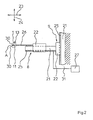
- in einer Seitenansicht zwei senkrecht zueinander wirkende Antriebe zum Bewegen eines Bewegungspunktes A der einen Schweißbacke der
Fig. 1 entlang einer umlaufenden Bahn; - Fig. 3:
- in einer schematischen Darstellung den Umlauf zweier gegeneinander bewegbarer, entlang eines effektiven Siegelweges den Folienschlauch der
Fig. 1 verschweißenden Schweißbacken, welche in einem Aufprallpunkt P gegeneinander stoßen; - Fig. 4:
- in einer schematischen Darstellung den Schweißbackenumlauf entsprechend
Fig. 3 , jedoch mit einem um eine Vorwärmstrecke und eine Kühlstrecke reduzierten effektiven Siegelweg, und einem anderen Aufprallpunkt P; - Fig. 5:
- in einem Diagramm den bekannten, mit herkömmlicher Technik erzielten funktionellen Zusammenhang zwischen der Zeit und dem Siegeldruck für Schweißbacken einer Quersiegelstation einer vertikalen Schlauchbeutelmaschine;
- Fig. 6:
- in einem Diagramm ein erfindungsgemäßes Siegelkraftprofil;
- Fig. 7:
- in einer schematischen Darstellung die Ultraschallsiegelung eines teilweise vierlagig liegenden Folienschlauchs zwischen den Schweißbacken der Quersiegelstation gemäß
Fig. 1 . - Bei einer vertikalen Schlauchbeutelmaschine 3 wird eine Folienbahn 14 mittels eines Abzuges 15 von einer Vorratsrolle 16 abgezogen, über eine Formschulter 17 gezogen und dabei zu einem Folienschlauch 7 geformt (
Fig. 1 ). Der Folienschlauch 7 wird mittels einer Längssiegeleinrichtung 18 in Transportrichtung 19 verschweißt und durch ein Füllrohr 20 befüllt. Zwei gegeneinander bewegbare, umlaufende Schweißbacken 1, 6 in einer Quersiegelstation 2 dienen dazu den Folienschlauch 7 quer zur Transportrichtung 19 mittels Quernähten 10 zu verschweißen. Eine Trenneinrichtung 11 in einer Schweißbacke 1 dient dazu, jeweils einen Schlauchbeutel 12 mit einer bestimmten Beutellänge vom Folienschlauch 7 abzutrennen. Die Schweißbacken 1, 6 werden derart betrieben, dass sie gegenläufig umlaufen, um längs eines effektiven Siegelweges Zseff die Verschweißung des mit gleicher Geschwindigkeit wie die Schweißbacken 1, 6 nach unten bewegten Folienschlauch 7 auszuführen (Fig. 3 ). Beide Schweißbacken 1, 6 werden dazu entlang einer jeweils geschlossenen Bahn 4 bewegt. Jede Bahn 4 weist einen geraden Abschnitt 5 auf, welcher zum Anliegen an dem zwischen den Schweißbacken 1, 6 zusammengedrückten Folienschlauch 7 vorgesehen ist. Dabei werden der Folienschlauch 7 und die Schweißbacken 1, 6 in Richtung des geraden Abschnittes 5 mit frei programmierbarer Geschwindigkeit weiterbewegt, um den Folienschlauch 7 durch die Ultraschalleinwirkung der Schweißbacken 1, 6 innerhalb einer Siegelzeit ts zu verschweißen. Durch die an den Siegelflächen 30 der Schweißbacken 1, 6 eingebrachten Ultraschallschwingungen wird die Folienbahn 14 des Folienschlauchs 7 teilweise aufgeschmolzen, so dass die paarweise einander gegenüberliegenden Schmelzbereiche - Es könnte aber auch ein Siegelweg Zs vorgegeben werden, welcher sich aus einer Vorwärmstrecke Zv für ein Vorwärmen des Gegenstandes mit vom Gegenstand beabstandeter Schweißbacke 1 , dem eigentlichen, effektiven Siegelweg Zseff und einer Kühlstrecke Zk zum Abkühlen des Gegenstandes bei vom Gegenstand beabstandeter Schweißbacke 1, währenddessen Kühlluft von einem an der Schweißbacke 1 vorgesehenen Kühlluftauslass 13 auf den Gegenstand geblasen wird, zusammensetzt (
Fig. 4 ). Damit diese Umstellung der Siegelwege Zs mit allen Orts- und Zeitparametern in einfacher Weise möglich ist, wurde für die Vorwärmstrecke Zv, den effektiven Siegelweg Zseff und die Kühlstrecke Zk jeweils ein bezüglich seiner Länge und seinen Ortskoordinaten frei wählbarer, parallel zum geraden Abschnitt 5 verlaufender Abschnitt 4a, 5, 4b vorgesehen, auf dem sich der Bewegungspunkt A entlang bewegt. Dazu werden die Antriebe 8, 9 (Fig. 2 ) derart betrieben, dass entlang der Bewegungsbahn beide Antriebe 8, 9 gleichzeitig betrieben und einander überlagert werden. Die geraden Abschnitte 4a, 5, 4b, sowie ihre genauen Längen und Ortskoordinaten können frei programmiert werden. An genau vorgegebenen Orten können also genau vorgegebene Geschwindigkeiten und, aus Gründen eines ruhigen Backenumlaufes, auch genau vorgegebene Beschleunigungen für die Schweißbacken 1, 6 vorgegeben werden. Auch die Rücksetzzeit zum erneuten Ansetzen der Schweißbacken 1, 6 an den Folienschlauch 7 und die Zykluszeit (Zeit für einen Backenumlauf) können frei ausgewählt werden. Eine entsprechende Software bringt die vorgewählten Parameter in die gewünschte Abhängigkeit und informiert über nicht zusammenpassende Eingaben. - Damit der Bewegungspunkt A ortsgenau bewegt werden kann, sind zum Bewegen der Schweißbacken 1, 6 jeweils zwei als Elektroantrieb ausgestaltete, senkrecht zueinander wirkende Antriebe 8, 9 vorgesehen. Dabei kann es sich beispielsweise um zwei elektromagnetischer Linearantriebe handeln. Statt solcher Linearantriebe sind aber auch beliebige andere Antriebskonfigurationen, insbesondere mit Getriebemotoren, denkbar. Diese Antriebe 8, 9 sind mit einer Steuereinrichtung 27 (über eine Leitung 31) verbunden. Zur Vermeidung irgendeiner Ortsungenauigkeit sind zum einen beide Antriebe 8, 9 mit einem Getriebe oder getriebelos miteinander und mit einer Schweißbacke 1, 6 verbunden. Zum anderen sind ortsverändernde Elastizitäten dadurch vermieden, dass jede Schweißbacke 1, 6 über eine starre Verbindung 26 mit dem beweglichen Teil 22 des horizontal wirkenden Antriebs 8 verbunden ist, und dass das antreibende Teil 21 dieses Antriebs 8 mit dem in vertikaler Richtung beweglichen Teil 22 des anderen Antriebs 9 starr verbunden ist. Die frei wählbaren Ortskoordinaten erlauben in jedem Punkt der Bahn 4 eine ideale Backenbewegung, auch bei relativ kompliziertem Bahnverlauf.
- Ein Aufeinanderprallen der Siegelflächen 30 der Schweißbacken 1, 6 geschieht jeweils in einem Aufprallpunkt P (
Fig. 3, Fig. 4 ), ab dem ein effektiver Siegelweg Zseff beginnt. Dieser Aufprallpunkt P liegt in einer Siegelebene S. Um ein sanftes Aufeinanderstoßen der Siegelflächen 30 und damit den Aufbau einer Siegelkraft (Fs) zu erreichen, wird die Normalkomponente VN eines jeweils in einer Siegelflächenebene mittig oder außermittig liegenden Bewegungspunktes A durch entsprechendes Ansteuern der beiden Antriebe 8, welche jeweils eine Schweißbacke 1, 6 in Normalrichtung bewegen, von der Steuereinrichtung 27, die über jeweils eine Leitung 31 (Fig. 2 ) mit jeweils einem antreibenden Teil 21 eines Antriebs 8 verbunden ist, gesteuert. - Die Siegelkraft Fs wird von einer Steuereinrichtung 27 einer Kraftsteuerung des Antriebs 8 während der Siegelzeit ts vorgegeben. Dabei wird im Falle eines getakteten Folientransportes jede Schweißbacke 1, 6 entlang einer linienförmigen Bahn bewegt, und bei Folienstillstand und am Folienschlauch 7 anliegenden Schweißbacken 1, 6 während der Siegelzeit ts eine zeitabhängige Siegelkraft Fs von der Steuereinrichtung 27 vorgegeben. Alternativ dazu wird bei kontinuierlichem Folientransport jede Schweißbacke 1, 6 entlang einer geschlossenen Bahn 4 bewegt, welche einen geraden Abschnitt 5 aufweist, entlang dessen bei bewegtem Folienschlauch 7 die mit ihm mitbewegte Schweißbacke 1, 6 den Folienschlauch 7 verschweißt, wobei die Siegelkraft Fs während der Siegeldauer zeitabhängig von der Steuereinrichtung 27 vorgegeben wird. Innerhalb der Siegeldauer wird dabei ein Siegelkraftprofil erreicht, da der die Normalkomponente und die Siegelkraft Fs erzeugende Antrieb 8 mit der Steuereinrichtung 27 verbunden ist, welche einen zeitlichen Verlauf für die Leistungsaufnahme des Antriebs 8 und damit die Siegelkraft 27 vorgibt. Dabei spielt es keine Rolle, ob die Leistungsaufnahme an sich oder eine mit ihr korrelierte Größe gesteuert und sodann zeitabhängig bis zum Erreichen der Siegelzeit ts geregelt wird.
- Beim bekannten Stand der Technik (
Fig. 5 ) hat die Siegelkraftkurve einen nahezu rechteckförmigen Verlauf. Die Siegelkraft steigt steil bis zu ihrem Maximalwert an und wird dort für bestimmte Siegelzeit konstant gehalten. Am Ende der Siegelzeit werden die Backen dann wieder geöffnet und die Siegelkraft fällt auf den Wert Null. Durch diesen aus dem Stand der Technik bekannten Siegelkraftverlauf wird ein hohes Maß an Energie verschwendet, da die hohe Siegelkraft zu Beginn des Siegelprozesses für die Erzielung einer guten Siegelqualität nicht erforderlich ist. Denn für das Einkoppeln der notwendigen Wärme in das Material des Folienschlauches reicht eine weit geringere Presskraft aus. -
Fig. 6 zeigt den Verlauf der Siegelkraftkurve bei einer beispielhaften Ausführungsform des erfindungsgemäßen Verfahrens. Demgemäß steigt erfindungsgemäß die Siegelkraftkurve zunächst bis zur Siegelkraft Fs1 bei einem ersten relativen Siegelkraftmaximum 33. Sobald dieses erste Siegelkraftmaximum 33, das von einer kurzzeitigen Kraftspitze gebildet wird, durchlaufen ist, wird die Siegelkraft 32 auf den Wert der Siegelkraft Fs2 des zweiten Siegelkraftmaximums 34 abgesenkt und dort für eine Haltezeit tH im Wesentlichen konstant gehalten. Alternativ dazu kann die Siegelkraft 32a bzw. 32b nach der Absenkung auch wieder bis zum Erreichen des zweiten Siegelkraftmaximums 34a bzw. 34b linear angehoben oder linear abgesenkt werden. Auch andere Siegelkraftverläufe sind im Grundsatz durch entsprechende Programmierung des Siegelkraftverlaufs denkbar. - Am Ende der Haltezeit tH wird die Siegelkraft 32 dann durch öffnen der Schweißbacken 1 und 6 auf den Nullwert abgesenkt. Die Dauer der Haltezeit tH ist dabei so abgestimmt, dass die zu verschweißende Folie bei Erreichen des Endes der Haltezeit tH zumindest teilweise aufgeschmolzen und verschweißt ist. Das Siegelkraftmaximum 33 bildet eine kurzzeitige Kraftspitze, die sich in einem kurzzeitigen Maximaldruckimpuls auf die Folie überträgt. Zur Erzeugung dieser kurzzeitigen Kraftspitze des Siegelkraftverlaufes beim ersten Siegelkraftmaximum wird der Antrieb 8 bzw. der Antrieb 9 der beiden Schweißbacken kurzzeitig im Überlastbetrieb betrieben, so dass die Antriebe 8 und 9 in ihrem Normalbetrieb entsprechend schwächer dimensioniert werden können. Nach Durchlaufen des zweiten Siegelkraftmaximums 34 werden die Schweißbacken 1 und 6 auseinander gefahren und die Siegelkraft 32 fällt dadurch auf den Wert Null. Um die Siegelkraft 32 möglichst schnell auf das erste Siegelkraftmaximum 33 steigern zu können, entspricht die Steigung der Flanke 35 an der Siegelkraftkurve 32 unmittelbar vor Erreichen des zweiten Siegelkraftmaximums der maximalen Leistung des Antriebs 8 bzw. 9 im Überlastbetrieb.
-
Fig. 7 zeigt in einer schematischen Darstellung die Ultraschallsiegelung eines teilweise vierlagig liegenden Folienschlauchs 7 zwischen den Schweißbacken 1 und 6 der Quersiegelstation 2 gemäßFig. 1 . Die äußeren Kanten 36 des Folienschlauchs 7 sind im Bereich der Quersiegelnähte eingefaltet, so dass die Folienbahn 14 in den eingefalteten Bereichen in vier Folienlagen 37, 38, 39 und 40 liegt. Die Folienlagen 37 und 38 bzw. die Folienlagen 39 und 40 werden durch die mit den Schweißbacken 1 und 6 an den Siegelflächen 30 eingebrachte Ultraschallschwingungen paarweise miteinander verschweißt. Durch die Anwendung des erfindungsgemäßen Verfahrens gelingt eine zuverlässige Ultraschallsiegelung auch in den Bereichen, in denen die Folienbahn 14 vierlagig übereinander liegt.
Claims (13)
- Verfahren zum Erzeugen einer Schweißkraft bzw. eines Schweißdruckes für eine Schweißbacke (1, 6), insbesondere eine Schweißbacke (1, 6) einer Quersiegelstation (2) einer vertikalen Schlauchbeutelmaschine (3), wobei die Schweißbacke (1, 6) entlang einer geschlossenen Bahn (4) umlaufend oder entlang einer linienförmigen Bahn (29) hin- und herbewegt wird, um gegen einen Widerstand, insbesondere eine zweite, gegenläufige Schweißbacke (1, 6) zu stoßen, wobei ein Folienschlauch (7) zwischen dem Widerstand und zumindest einer Siegelfläche (30) der Schweißbacke (1, 6) zusammengedrückt wird, um den Folienschlauch (7) mittels über die Siegelfläche (30) in den Folienschlauch (7) eingebrachten Ultraschallschwingungen bei einem ausgeübten Druck in einer Siegelebene (S) unter einer Siegelkraft (Fs) innerhalb einer Siegelzeit (ts) zu verschweißen, und wobei zumindest ein Antrieb (8, 9) dazu vorgesehen ist, die Schweißbacke (1, 6) in einer Normalrichtung zu einer Oberfläche des Widerstandes hin zu bewegen, um derart den Schweißvorgang ortsfest oder entlang eines effektiven Siegelweges (Zseff) innerhalb der Siegelzeit (ts) durchzuführen, und wobei die Siegelkraft (Fs) oder ein mit der Siegelkraft (Fs) korrelierender Siegelparameter, insbesondere der Siegeldruck oder die Antriebsleistung des Antriebs (8, 9), von einer Steuereinrichtung (27) während der Siegelzeit (ts) derart vorgegeben wird, dass die Siegelkraft (Fs) innerhalb der Siegelzeit (ts) entlang einer Siegelkraftkurve (32) verläuft,
dadurch gekennzeichnet,
dass die Siegelkraftkurve (32) ein erstes relatives Siegelkraftmaximum (33) mit einer Siegelkraft (Fs1) und zumindest ein zweites relatives Siegelkraftmaximum (34) mit einer Siegelkraft (Fs2) aufweist, wobei die Siegelkraft (Fs1) beim ersten Siegelkraftmaximum (33) höher ist als die Siegelkraft (Fs2) beim zweiten Siegelkraftmaximum (34). - Verfahren nach Anspruch 1,
dadurch gekennzeichnet,
dass der Folienschlauch mit mehr als zwei paarweise angeordneten Folienlagen (37, 38, 39, 40), insbesondere in vier Folienlagen (37, 38, 39, 40), zwischen den Schweißbacke (1, 6) zusammengedrückt wird, wobei die paarweise angeordneten Folienlagen (37, 38, 39, 40) mittels über die Siegelfläche (30) in den Folienschlauch (7) eingebrachten Ultraschallschwingungen paarweise verschweißt werden. - Verfahren nach Anspruch 1 oder 2,
dadurch gekennzeichnet,
dass die Siegelkraft (Fs2) des zweiten Siegelkraftmaximums (34) im Bereich von 30 bis 70 %, insbesondere im Bereich von 45% bis 55% der Siegelkraft (Fs1) des ersten Siegelkraftmaximums (33) liegt. - Verfahren nach einem der Ansprüche 1 bis 3,
dadurch gekennzeichnet,
dass die Siegelkraft (Fs1) des zweiten Siegelkraftmaximums (33) von einer kurzzeitigen Kraftspitze gebildet wird. - Verfahren nach Anspruch 4,
dadurch gekennzeichnet,
dass die kurzzeitige Kraftspitze des zweiten Siegelkraftmaximums (33) durch kurzzeitigen Überlastbetrieb des Antriebs (8, 9) der Schweißbacke (1, 6) erzeugt wird. - Verfahren nach einem der Ansprüche 1 bis 5,
dadurch gekennzeichnet,
dass die Steigung der Flanke (35) an der Siegelkraftkurve (32) unmittelbar vor Erreichen des ersten Siegelkraftmaximums (33) der maximalen Leistung des Antriebs (8, 9) im Überlastbetrieb entspricht. - Verfahren nach einem der Ansprüche 1 bis 6,
dadurch gekennzeichnet,
dass die die Siegelkraft (Fs) nach Durchlaufen des ersten Siegelkraftmaximums (33) auf den Wert der Siegelkraft (Fs2) des zweiten Siegelkraftmaximums (34) abgesenkt und für eine Haltezeit (tH) im Wesentlichen konstant bei der der Siegelkraft (Fs2) des zweiten Siegelkraftmaximums (34) gehalten wird. - Verfahren nach Anspruch 7,
dadurch gekennzeichnet,
dass die Haltezeit (tH) erst endet, wenn die Schmelzschicht des Folienschlauchs (7) zumindest teilweise aufgeschmolzen und verschweißt ist. - Verfahren nach einem der Ansprüche 1 bis 8,
dadurch gekennzeichnet,
dass die Siegelkraft (Fs1) des ersten Siegelkraftmaximums (33) und/oder die Siegelkraft (Fs2) des zweiten Siegelkraftmaximums (34) in der Antriebssteuerung variabel einstellbar sind. - Verfahren nach einem der Ansprüche 1 bis 9,
dadurch gekennzeichnet,
dass die Zeit (ts1) bis zum Erreichen des ersten Siegelkraftmaximums (33) und/oder die Zeit (ts2) bis zum Erreichen des zweiten Siegelkraftmaximums (34) und/oder die Haltezeit (tH) in der Antriebssteuerung variabel einstellbar ist. - Verfahren nach einem der Ansprüche 1 bis 10,
dadurch gekennzeichnet,
dass die die Siegelkraft (Fs) nach Durchlaufen des zweiten Siegelkraftmaximums (34), durch Öffnen der Schweißbacken (1, 6) auf Null gebracht wird. - Verfahren nach einem der Ansprüche 1 bis 11,
dadurch gekennzeichnet,
dass die die Siegelkraft (Fs) nach Durchlaufen des zweiten Siegelkraftmaximums (34) auf einen Zwischenwert abgesenkt und dann, insbesondere konstant, gehalten wird und erst danach durch Öffnen der Schweißbacken (1, 6) auf Null gebracht wird. - Verfahren nach einem der Ansprüche 1 bis 12,
dadurch gekennzeichnet,
dass die Schweißbacken (1, 6) entlang einer geschlossenen Bahn (4) bewegt werden, die einen geraden Abschnitt (5) aufweist, entlang dessen bei bewegtem Folienschlauch (7) die mit ihm mitbewegten Schweißbacken (1, 6) den Folienschlauch (7) verschweißen.
Applications Claiming Priority (2)
| Application Number | Priority Date | Filing Date | Title |
|---|---|---|---|
| DE102010050008 | 2010-11-02 | ||
| DE102011006506A DE102011006506B4 (de) | 2010-11-02 | 2011-03-31 | Ultraschall-Heißsiegelverfahren mit Siegel-Druckregelung |
Publications (3)
| Publication Number | Publication Date |
|---|---|
| EP2447041A2 true EP2447041A2 (de) | 2012-05-02 |
| EP2447041A3 EP2447041A3 (de) | 2013-12-04 |
| EP2447041B1 EP2447041B1 (de) | 2015-03-18 |
Family
ID=44799886
Family Applications (1)
| Application Number | Title | Priority Date | Filing Date |
|---|---|---|---|
| EP11185661.3A Active EP2447041B1 (de) | 2010-11-02 | 2011-10-18 | Ultraschall-Heißsiegelverfahren mit Siegel-Druckregelung |
Country Status (3)
| Country | Link |
|---|---|
| US (1) | US8308881B2 (de) |
| EP (1) | EP2447041B1 (de) |
| DE (1) | DE102011006506B4 (de) |
Families Citing this family (8)
| Publication number | Priority date | Publication date | Assignee | Title |
|---|---|---|---|---|
| ES2750616T3 (es) * | 2013-11-12 | 2020-03-26 | Dukane Ias Llc | Método de soldadura ultrasónica de partes termoplásticas |
| US9510713B2 (en) * | 2014-08-25 | 2016-12-06 | II Joe Thomas Farris | Methods for sewing T-pocket towels |
| JP6706045B2 (ja) * | 2015-10-09 | 2020-06-03 | 大森機械工業株式会社 | ピロー包装機 |
| PL3807080T3 (pl) | 2018-06-13 | 2025-07-21 | Dukane Ias, Llc | Sposoby określania grubości warstwy stopionej związanej z ustaloną wytrzymałością zgrzewu na podstawie korelacji pomiędzy nimi |
| US11447281B2 (en) * | 2020-02-14 | 2022-09-20 | Lako Tool & Manufacturing, Inc. | Modular stand-alone ultrasonic sealing system |
| EP3909879B1 (de) * | 2020-05-12 | 2023-10-18 | Teepack Spezialmaschinen GmbH & Co. KG | Vorrichtung zum herstellen eines in einer umhüllung aufgenommenen beutels |
| DE102021112794B4 (de) | 2021-05-18 | 2023-12-21 | Rovema Gmbh | Verfahren zum Betrieb einer Schlauchbeutelmaschine |
| CN116280660A (zh) * | 2022-12-30 | 2023-06-23 | 温州市炎龙工艺品有限公司 | 一种功能性保温袋及其专用制袋机和制备工艺 |
Citations (2)
| Publication number | Priority date | Publication date | Assignee | Title |
|---|---|---|---|---|
| DE4425207A1 (de) | 1994-07-16 | 1996-01-18 | Rovema Gmbh | Schlauchbeutelmaschine |
| DE102004049376A1 (de) | 2004-10-09 | 2006-04-13 | Rovema Verpackungsmaschinen Gmbh | Verfahren und Vorrichtung zum Erzeugen einer Schweißkraft |
Family Cites Families (6)
| Publication number | Priority date | Publication date | Assignee | Title |
|---|---|---|---|---|
| IT1139239B (it) * | 1981-10-16 | 1986-09-24 | Grace Italiana Spa | Apparecchiatura e procedimento per il confezionamento sottovuoto |
| US4583347A (en) * | 1982-10-07 | 1986-04-22 | W. R. Grace & Co., Cryovac Div. | Vacuum packaging apparatus and process |
| US5826407A (en) * | 1997-10-07 | 1998-10-27 | Tetra Laval Holdings & Finance, S.A. | Method of ultrasonically vibrating a workpiece |
| US8052816B2 (en) * | 2006-05-08 | 2011-11-08 | Dukane Corporation | Ultrasonic press using servo motor with delayed motion |
| WO2008018935A2 (en) * | 2006-05-08 | 2008-02-14 | Dukane Corporation | Ultrasonic press using servo motor with integrated linear actuator |
| JP5779761B2 (ja) * | 2011-09-15 | 2015-09-16 | 精電舎電子工業株式会社 | 超音波溶着装置、超音波接合装置、布線装置 |
-
2011
- 2011-03-31 DE DE102011006506A patent/DE102011006506B4/de active Active
- 2011-10-18 EP EP11185661.3A patent/EP2447041B1/de active Active
- 2011-11-01 US US13/286,560 patent/US8308881B2/en active Active
Patent Citations (2)
| Publication number | Priority date | Publication date | Assignee | Title |
|---|---|---|---|---|
| DE4425207A1 (de) | 1994-07-16 | 1996-01-18 | Rovema Gmbh | Schlauchbeutelmaschine |
| DE102004049376A1 (de) | 2004-10-09 | 2006-04-13 | Rovema Verpackungsmaschinen Gmbh | Verfahren und Vorrichtung zum Erzeugen einer Schweißkraft |
Also Published As
| Publication number | Publication date |
|---|---|
| DE102011006506B4 (de) | 2013-11-07 |
| DE102011006506A1 (de) | 2012-05-03 |
| EP2447041B1 (de) | 2015-03-18 |
| US20120125521A1 (en) | 2012-05-24 |
| EP2447041A3 (de) | 2013-12-04 |
| US8308881B2 (en) | 2012-11-13 |
Similar Documents
| Publication | Publication Date | Title |
|---|---|---|
| EP2447041B1 (de) | Ultraschall-Heißsiegelverfahren mit Siegel-Druckregelung | |
| DE102014115535B3 (de) | Rührreibschweißwerkzeug sowie Verfahren zum Rührreibschweißen | |
| EP2447043B1 (de) | Verfahren zur energieeffizienten Siegelung von einem Folienschlauch | |
| EP3102387B1 (de) | Ultraschallschweissvorrichtung mit vorwärmeinrichtung | |
| EP2483165A1 (de) | Vorrichtung und verfahren zum formen, füllen und verschliessen von jeweils eine ausgiesseinrichtung aufweisenden beuteln | |
| WO2018104515A1 (de) | Sackherstellvorrichtung und verfahren | |
| EP2812174B1 (de) | Verfahren und vorrichtung zur konfektionierung von schlauchbeuteln aus dünnen kunststofffolien mittels eines ultraschall-schweissverfahrens | |
| EP1648648A1 (de) | Mehrkopf-reibschweissverfahren und vorrichtung zur durchführung des verfahrens | |
| DE102004049375A1 (de) | Verfahren und Vorrichtung zum Positionieren einer Schweißbacke | |
| WO2012093112A1 (de) | Vorrichtung und verfahren zur herstellung von tubenrohren für verpackungstuben | |
| EP3296081B1 (de) | Verfahren und vorrichtung zum herstellen von schlauchbeuteln | |
| DE102016004180A1 (de) | Vorrichtung zum Ultraschallschweißen | |
| WO2012107522A1 (de) | Verfahren zur herstellung einer quersiegelnaht sowie quersiegelvorrichtung | |
| DE19906873A1 (de) | Vorrichtung zum Fügen von Materiallagen durch Ultraschallschweißen | |
| EP2024167A2 (de) | Vorrichtung zum verschweissen einer folienbahn | |
| EP1642700B1 (de) | Verfahren und Vorrichtung zum Bewegen einer Schweissbacke | |
| DE102004049376B4 (de) | Verfahren zum Erzeugen einer Schweißkraft | |
| DE102007003930A1 (de) | Schlauchbeutelmaschine | |
| WO2018141660A1 (de) | Verfahren und vorrichtung zum ultraschallverbinden von fügepartnern | |
| EP3177442A1 (de) | Verfahren und vorrichtung zum herstellen von säcken oder beuteln sowie säcke oder beutel | |
| DE102007004140B4 (de) | Schlauchbeutelmaschine | |
| DE102012003547A1 (de) | Ultraschallsystem | |
| DE102004046971A1 (de) | Verfahren und Vorrichtung zum Bewegen einer Schweißbacke | |
| EP3047962B1 (de) | Vorrichtung zum versiegeln einer verpackung oder eines verpackungsmaterials | |
| DE102014216990B4 (de) | Verfahren und Vorrichtung zum Schweißen differierender Schweißlagen eines Produktes |
Legal Events
| Date | Code | Title | Description |
|---|---|---|---|
| PUAI | Public reference made under article 153(3) epc to a published international application that has entered the european phase |
Free format text: ORIGINAL CODE: 0009012 |
|
| AK | Designated contracting states |
Kind code of ref document: A2 Designated state(s): AL AT BE BG CH CY CZ DE DK EE ES FI FR GB GR HR HU IE IS IT LI LT LU LV MC MK MT NL NO PL PT RO RS SE SI SK SM TR |
|
| AX | Request for extension of the european patent |
Extension state: BA ME |
|
| PUAL | Search report despatched |
Free format text: ORIGINAL CODE: 0009013 |
|
| AK | Designated contracting states |
Kind code of ref document: A3 Designated state(s): AL AT BE BG CH CY CZ DE DK EE ES FI FR GB GR HR HU IE IS IT LI LT LU LV MC MK MT NL NO PL PT RO RS SE SI SK SM TR |
|
| AX | Request for extension of the european patent |
Extension state: BA ME |
|
| RIC1 | Information provided on ipc code assigned before grant |
Ipc: B65B 51/30 20060101ALN20131030BHEP Ipc: B65B 9/20 20120101ALN20131030BHEP Ipc: B65B 51/14 20060101ALI20131030BHEP Ipc: B65B 51/22 20060101ALI20131030BHEP Ipc: B29C 65/08 20060101AFI20131030BHEP |
|
| 17P | Request for examination filed |
Effective date: 20140312 |
|
| RBV | Designated contracting states (corrected) |
Designated state(s): AL AT BE BG CH CY CZ DE DK EE ES FI FR GB GR HR HU IE IS IT LI LT LU LV MC MK MT NL NO PL PT RO RS SE SI SK SM TR |
|
| GRAP | Despatch of communication of intention to grant a patent |
Free format text: ORIGINAL CODE: EPIDOSNIGR1 |
|
| RIC1 | Information provided on ipc code assigned before grant |
Ipc: B65B 51/30 20060101ALI20141014BHEP Ipc: B65B 51/22 20060101ALI20141014BHEP Ipc: B29C 65/08 20060101AFI20141014BHEP Ipc: B65B 9/213 20120101ALN20141014BHEP Ipc: B65B 9/207 20120101ALN20141014BHEP |
|
| INTG | Intention to grant announced |
Effective date: 20141031 |
|
| GRAS | Grant fee paid |
Free format text: ORIGINAL CODE: EPIDOSNIGR3 |
|
| GRAA | (expected) grant |
Free format text: ORIGINAL CODE: 0009210 |
|
| AK | Designated contracting states |
Kind code of ref document: B1 Designated state(s): AL AT BE BG CH CY CZ DE DK EE ES FI FR GB GR HR HU IE IS IT LI LT LU LV MC MK MT NL NO PL PT RO RS SE SI SK SM TR |
|
| REG | Reference to a national code |
Ref country code: GB Ref legal event code: FG4D Free format text: NOT ENGLISH |
|
| REG | Reference to a national code |
Ref country code: CH Ref legal event code: EP |
|
| REG | Reference to a national code |
Ref country code: IE Ref legal event code: FG4D Free format text: LANGUAGE OF EP DOCUMENT: GERMAN |
|
| REG | Reference to a national code |
Ref country code: AT Ref legal event code: REF Ref document number: 716268 Country of ref document: AT Kind code of ref document: T Effective date: 20150415 |
|
| REG | Reference to a national code |
Ref country code: DE Ref legal event code: R096 Ref document number: 502011006266 Country of ref document: DE Effective date: 20150430 |
|
| REG | Reference to a national code |
Ref country code: NL Ref legal event code: T3 |
|
| PG25 | Lapsed in a contracting state [announced via postgrant information from national office to epo] |
Ref country code: NO Free format text: LAPSE BECAUSE OF FAILURE TO SUBMIT A TRANSLATION OF THE DESCRIPTION OR TO PAY THE FEE WITHIN THE PRESCRIBED TIME-LIMIT Effective date: 20150618 Ref country code: LT Free format text: LAPSE BECAUSE OF FAILURE TO SUBMIT A TRANSLATION OF THE DESCRIPTION OR TO PAY THE FEE WITHIN THE PRESCRIBED TIME-LIMIT Effective date: 20150318 Ref country code: HR Free format text: LAPSE BECAUSE OF FAILURE TO SUBMIT A TRANSLATION OF THE DESCRIPTION OR TO PAY THE FEE WITHIN THE PRESCRIBED TIME-LIMIT Effective date: 20150318 Ref country code: SE Free format text: LAPSE BECAUSE OF FAILURE TO SUBMIT A TRANSLATION OF THE DESCRIPTION OR TO PAY THE FEE WITHIN THE PRESCRIBED TIME-LIMIT Effective date: 20150318 Ref country code: FI Free format text: LAPSE BECAUSE OF FAILURE TO SUBMIT A TRANSLATION OF THE DESCRIPTION OR TO PAY THE FEE WITHIN THE PRESCRIBED TIME-LIMIT Effective date: 20150318 |
|
| REG | Reference to a national code |
Ref country code: LT Ref legal event code: MG4D |
|
| PG25 | Lapsed in a contracting state [announced via postgrant information from national office to epo] |
Ref country code: GR Free format text: LAPSE BECAUSE OF FAILURE TO SUBMIT A TRANSLATION OF THE DESCRIPTION OR TO PAY THE FEE WITHIN THE PRESCRIBED TIME-LIMIT Effective date: 20150619 Ref country code: LV Free format text: LAPSE BECAUSE OF FAILURE TO SUBMIT A TRANSLATION OF THE DESCRIPTION OR TO PAY THE FEE WITHIN THE PRESCRIBED TIME-LIMIT Effective date: 20150318 Ref country code: RS Free format text: LAPSE BECAUSE OF FAILURE TO SUBMIT A TRANSLATION OF THE DESCRIPTION OR TO PAY THE FEE WITHIN THE PRESCRIBED TIME-LIMIT Effective date: 20150318 |
|
| PG25 | Lapsed in a contracting state [announced via postgrant information from national office to epo] |
Ref country code: CZ Free format text: LAPSE BECAUSE OF FAILURE TO SUBMIT A TRANSLATION OF THE DESCRIPTION OR TO PAY THE FEE WITHIN THE PRESCRIBED TIME-LIMIT Effective date: 20150318 Ref country code: ES Free format text: LAPSE BECAUSE OF FAILURE TO SUBMIT A TRANSLATION OF THE DESCRIPTION OR TO PAY THE FEE WITHIN THE PRESCRIBED TIME-LIMIT Effective date: 20150318 Ref country code: SK Free format text: LAPSE BECAUSE OF FAILURE TO SUBMIT A TRANSLATION OF THE DESCRIPTION OR TO PAY THE FEE WITHIN THE PRESCRIBED TIME-LIMIT Effective date: 20150318 Ref country code: RO Free format text: LAPSE BECAUSE OF FAILURE TO SUBMIT A TRANSLATION OF THE DESCRIPTION OR TO PAY THE FEE WITHIN THE PRESCRIBED TIME-LIMIT Effective date: 20150318 Ref country code: EE Free format text: LAPSE BECAUSE OF FAILURE TO SUBMIT A TRANSLATION OF THE DESCRIPTION OR TO PAY THE FEE WITHIN THE PRESCRIBED TIME-LIMIT Effective date: 20150318 Ref country code: PT Free format text: LAPSE BECAUSE OF FAILURE TO SUBMIT A TRANSLATION OF THE DESCRIPTION OR TO PAY THE FEE WITHIN THE PRESCRIBED TIME-LIMIT Effective date: 20150720 |
|
| PG25 | Lapsed in a contracting state [announced via postgrant information from national office to epo] |
Ref country code: PL Free format text: LAPSE BECAUSE OF FAILURE TO SUBMIT A TRANSLATION OF THE DESCRIPTION OR TO PAY THE FEE WITHIN THE PRESCRIBED TIME-LIMIT Effective date: 20150318 Ref country code: IS Free format text: LAPSE BECAUSE OF FAILURE TO SUBMIT A TRANSLATION OF THE DESCRIPTION OR TO PAY THE FEE WITHIN THE PRESCRIBED TIME-LIMIT Effective date: 20150718 |
|
| REG | Reference to a national code |
Ref country code: DE Ref legal event code: R097 Ref document number: 502011006266 Country of ref document: DE |
|
| PLBE | No opposition filed within time limit |
Free format text: ORIGINAL CODE: 0009261 |
|
| STAA | Information on the status of an ep patent application or granted ep patent |
Free format text: STATUS: NO OPPOSITION FILED WITHIN TIME LIMIT |
|
| PG25 | Lapsed in a contracting state [announced via postgrant information from national office to epo] |
Ref country code: DK Free format text: LAPSE BECAUSE OF FAILURE TO SUBMIT A TRANSLATION OF THE DESCRIPTION OR TO PAY THE FEE WITHIN THE PRESCRIBED TIME-LIMIT Effective date: 20150318 |
|
| 26N | No opposition filed |
Effective date: 20151221 |
|
| PG25 | Lapsed in a contracting state [announced via postgrant information from national office to epo] |
Ref country code: SI Free format text: LAPSE BECAUSE OF FAILURE TO SUBMIT A TRANSLATION OF THE DESCRIPTION OR TO PAY THE FEE WITHIN THE PRESCRIBED TIME-LIMIT Effective date: 20150318 |
|
| PG25 | Lapsed in a contracting state [announced via postgrant information from national office to epo] |
Ref country code: LU Free format text: LAPSE BECAUSE OF FAILURE TO SUBMIT A TRANSLATION OF THE DESCRIPTION OR TO PAY THE FEE WITHIN THE PRESCRIBED TIME-LIMIT Effective date: 20151018 |
|
| REG | Reference to a national code |
Ref country code: CH Ref legal event code: PL |
|
| PG25 | Lapsed in a contracting state [announced via postgrant information from national office to epo] |
Ref country code: MC Free format text: LAPSE BECAUSE OF FAILURE TO SUBMIT A TRANSLATION OF THE DESCRIPTION OR TO PAY THE FEE WITHIN THE PRESCRIBED TIME-LIMIT Effective date: 20150318 |
|
| REG | Reference to a national code |
Ref country code: IE Ref legal event code: MM4A |
|
| PG25 | Lapsed in a contracting state [announced via postgrant information from national office to epo] |
Ref country code: LI Free format text: LAPSE BECAUSE OF NON-PAYMENT OF DUE FEES Effective date: 20151031 Ref country code: CH Free format text: LAPSE BECAUSE OF NON-PAYMENT OF DUE FEES Effective date: 20151031 |
|
| REG | Reference to a national code |
Ref country code: FR Ref legal event code: ST Effective date: 20160630 |
|
| PG25 | Lapsed in a contracting state [announced via postgrant information from national office to epo] |
Ref country code: FR Free format text: LAPSE BECAUSE OF NON-PAYMENT OF DUE FEES Effective date: 20151102 |
|
| PG25 | Lapsed in a contracting state [announced via postgrant information from national office to epo] |
Ref country code: IE Free format text: LAPSE BECAUSE OF NON-PAYMENT OF DUE FEES Effective date: 20151018 |
|
| PG25 | Lapsed in a contracting state [announced via postgrant information from national office to epo] |
Ref country code: HU Free format text: LAPSE BECAUSE OF FAILURE TO SUBMIT A TRANSLATION OF THE DESCRIPTION OR TO PAY THE FEE WITHIN THE PRESCRIBED TIME-LIMIT; INVALID AB INITIO Effective date: 20111018 Ref country code: BG Free format text: LAPSE BECAUSE OF FAILURE TO SUBMIT A TRANSLATION OF THE DESCRIPTION OR TO PAY THE FEE WITHIN THE PRESCRIBED TIME-LIMIT Effective date: 20150318 Ref country code: SM Free format text: LAPSE BECAUSE OF FAILURE TO SUBMIT A TRANSLATION OF THE DESCRIPTION OR TO PAY THE FEE WITHIN THE PRESCRIBED TIME-LIMIT Effective date: 20150318 |
|
| PG25 | Lapsed in a contracting state [announced via postgrant information from national office to epo] |
Ref country code: CY Free format text: LAPSE BECAUSE OF FAILURE TO SUBMIT A TRANSLATION OF THE DESCRIPTION OR TO PAY THE FEE WITHIN THE PRESCRIBED TIME-LIMIT Effective date: 20150318 |
|
| PG25 | Lapsed in a contracting state [announced via postgrant information from national office to epo] |
Ref country code: BE Free format text: LAPSE BECAUSE OF NON-PAYMENT OF DUE FEES Effective date: 20151031 |
|
| PG25 | Lapsed in a contracting state [announced via postgrant information from national office to epo] |
Ref country code: TR Free format text: LAPSE BECAUSE OF FAILURE TO SUBMIT A TRANSLATION OF THE DESCRIPTION OR TO PAY THE FEE WITHIN THE PRESCRIBED TIME-LIMIT Effective date: 20150318 Ref country code: MT Free format text: LAPSE BECAUSE OF FAILURE TO SUBMIT A TRANSLATION OF THE DESCRIPTION OR TO PAY THE FEE WITHIN THE PRESCRIBED TIME-LIMIT Effective date: 20150318 |
|
| REG | Reference to a national code |
Ref country code: AT Ref legal event code: MM01 Ref document number: 716268 Country of ref document: AT Kind code of ref document: T Effective date: 20161018 |
|
| PG25 | Lapsed in a contracting state [announced via postgrant information from national office to epo] |
Ref country code: AT Free format text: LAPSE BECAUSE OF NON-PAYMENT OF DUE FEES Effective date: 20161018 |
|
| PG25 | Lapsed in a contracting state [announced via postgrant information from national office to epo] |
Ref country code: MK Free format text: LAPSE BECAUSE OF FAILURE TO SUBMIT A TRANSLATION OF THE DESCRIPTION OR TO PAY THE FEE WITHIN THE PRESCRIBED TIME-LIMIT Effective date: 20150318 |
|
| PG25 | Lapsed in a contracting state [announced via postgrant information from national office to epo] |
Ref country code: AL Free format text: LAPSE BECAUSE OF FAILURE TO SUBMIT A TRANSLATION OF THE DESCRIPTION OR TO PAY THE FEE WITHIN THE PRESCRIBED TIME-LIMIT Effective date: 20150318 |
|
| P01 | Opt-out of the competence of the unified patent court (upc) registered |
Effective date: 20230524 |
|
| PGFP | Annual fee paid to national office [announced via postgrant information from national office to epo] |
Ref country code: GB Payment date: 20231025 Year of fee payment: 13 |
|
| GBPC | Gb: european patent ceased through non-payment of renewal fee |
Effective date: 20241018 |
|
| PG25 | Lapsed in a contracting state [announced via postgrant information from national office to epo] |
Ref country code: GB Free format text: LAPSE BECAUSE OF NON-PAYMENT OF DUE FEES Effective date: 20241018 |
|
| PGFP | Annual fee paid to national office [announced via postgrant information from national office to epo] |
Ref country code: NL Payment date: 20251119 Year of fee payment: 15 |
|
| PGFP | Annual fee paid to national office [announced via postgrant information from national office to epo] |
Ref country code: DE Payment date: 20251215 Year of fee payment: 15 |
|
| PGFP | Annual fee paid to national office [announced via postgrant information from national office to epo] |
Ref country code: IT Payment date: 20251121 Year of fee payment: 15 |