EP2447032A2 - Verfahren zur Herstellung eines Möbelteils - Google Patents
Verfahren zur Herstellung eines Möbelteils Download PDFInfo
- Publication number
- EP2447032A2 EP2447032A2 EP11405341A EP11405341A EP2447032A2 EP 2447032 A2 EP2447032 A2 EP 2447032A2 EP 11405341 A EP11405341 A EP 11405341A EP 11405341 A EP11405341 A EP 11405341A EP 2447032 A2 EP2447032 A2 EP 2447032A2
- Authority
- EP
- European Patent Office
- Prior art keywords
- pressing
- zones
- producing
- starting workpiece
- mold
- Prior art date
- Legal status (The legal status is an assumption and is not a legal conclusion. Google has not performed a legal analysis and makes no representation as to the accuracy of the status listed.)
- Granted
Links
- 238000004519 manufacturing process Methods 0.000 title claims description 7
- 238000003825 pressing Methods 0.000 claims abstract description 38
- 238000000034 method Methods 0.000 claims abstract description 11
- 238000001816 cooling Methods 0.000 claims description 8
- 238000004049 embossing Methods 0.000 claims description 6
- 238000013016 damping Methods 0.000 claims description 5
- 239000012790 adhesive layer Substances 0.000 claims description 4
- 238000002844 melting Methods 0.000 claims description 3
- 230000008018 melting Effects 0.000 claims description 3
- 239000004744 fabric Substances 0.000 claims description 2
- 239000000835 fiber Substances 0.000 claims description 2
- 239000002657 fibrous material Substances 0.000 claims description 2
- 239000000203 mixture Substances 0.000 claims description 2
- 239000012209 synthetic fiber Substances 0.000 claims description 2
- 229920002994 synthetic fiber Polymers 0.000 claims description 2
- 210000002268 wool Anatomy 0.000 claims description 2
- 238000000465 moulding Methods 0.000 description 8
- 125000006850 spacer group Chemical group 0.000 description 5
- 239000000463 material Substances 0.000 description 3
- 230000004913 activation Effects 0.000 description 1
- 230000000295 complement effect Effects 0.000 description 1
- 238000003780 insertion Methods 0.000 description 1
- 230000037431 insertion Effects 0.000 description 1
- 238000009434 installation Methods 0.000 description 1
- 238000003032 molecular docking Methods 0.000 description 1
Images





Classifications
-
- B—PERFORMING OPERATIONS; TRANSPORTING
- B29—WORKING OF PLASTICS; WORKING OF SUBSTANCES IN A PLASTIC STATE IN GENERAL
- B29C—SHAPING OR JOINING OF PLASTICS; SHAPING OF MATERIAL IN A PLASTIC STATE, NOT OTHERWISE PROVIDED FOR; AFTER-TREATMENT OF THE SHAPED PRODUCTS, e.g. REPAIRING
- B29C43/00—Compression moulding, i.e. applying external pressure to flow the moulding material; Apparatus therefor
- B29C43/02—Compression moulding, i.e. applying external pressure to flow the moulding material; Apparatus therefor of articles of definite length, i.e. discrete articles
- B29C43/021—Compression moulding, i.e. applying external pressure to flow the moulding material; Apparatus therefor of articles of definite length, i.e. discrete articles characterised by the shape of the surface
-
- B—PERFORMING OPERATIONS; TRANSPORTING
- B29—WORKING OF PLASTICS; WORKING OF SUBSTANCES IN A PLASTIC STATE IN GENERAL
- B29C—SHAPING OR JOINING OF PLASTICS; SHAPING OF MATERIAL IN A PLASTIC STATE, NOT OTHERWISE PROVIDED FOR; AFTER-TREATMENT OF THE SHAPED PRODUCTS, e.g. REPAIRING
- B29C43/00—Compression moulding, i.e. applying external pressure to flow the moulding material; Apparatus therefor
- B29C43/006—Pressing and sintering powders, granules or fibres
-
- B—PERFORMING OPERATIONS; TRANSPORTING
- B27—WORKING OR PRESERVING WOOD OR SIMILAR MATERIAL; NAILING OR STAPLING MACHINES IN GENERAL
- B27N—MANUFACTURE BY DRY PROCESSES OF ARTICLES, WITH OR WITHOUT ORGANIC BINDING AGENTS, MADE FROM PARTICLES OR FIBRES CONSISTING OF WOOD OR OTHER LIGNOCELLULOSIC OR LIKE ORGANIC MATERIAL
- B27N3/00—Manufacture of substantially flat articles, e.g. boards, from particles or fibres
-
- B—PERFORMING OPERATIONS; TRANSPORTING
- B29—WORKING OF PLASTICS; WORKING OF SUBSTANCES IN A PLASTIC STATE IN GENERAL
- B29C—SHAPING OR JOINING OF PLASTICS; SHAPING OF MATERIAL IN A PLASTIC STATE, NOT OTHERWISE PROVIDED FOR; AFTER-TREATMENT OF THE SHAPED PRODUCTS, e.g. REPAIRING
- B29C43/00—Compression moulding, i.e. applying external pressure to flow the moulding material; Apparatus therefor
- B29C43/02—Compression moulding, i.e. applying external pressure to flow the moulding material; Apparatus therefor of articles of definite length, i.e. discrete articles
- B29C43/021—Compression moulding, i.e. applying external pressure to flow the moulding material; Apparatus therefor of articles of definite length, i.e. discrete articles characterised by the shape of the surface
- B29C2043/022—Compression moulding, i.e. applying external pressure to flow the moulding material; Apparatus therefor of articles of definite length, i.e. discrete articles characterised by the shape of the surface having locally depressed lines, e.g. hinges
-
- B—PERFORMING OPERATIONS; TRANSPORTING
- B29—WORKING OF PLASTICS; WORKING OF SUBSTANCES IN A PLASTIC STATE IN GENERAL
- B29C—SHAPING OR JOINING OF PLASTICS; SHAPING OF MATERIAL IN A PLASTIC STATE, NOT OTHERWISE PROVIDED FOR; AFTER-TREATMENT OF THE SHAPED PRODUCTS, e.g. REPAIRING
- B29C43/00—Compression moulding, i.e. applying external pressure to flow the moulding material; Apparatus therefor
- B29C43/32—Component parts, details or accessories; Auxiliary operations
- B29C43/36—Moulds for making articles of definite length, i.e. discrete articles
- B29C2043/366—Moulds for making articles of definite length, i.e. discrete articles plates pressurized by an actuator, e.g. ram drive, screw, vulcanizing presses
-
- B—PERFORMING OPERATIONS; TRANSPORTING
- B29—WORKING OF PLASTICS; WORKING OF SUBSTANCES IN A PLASTIC STATE IN GENERAL
- B29K—INDEXING SCHEME ASSOCIATED WITH SUBCLASSES B29B, B29C OR B29D, RELATING TO MOULDING MATERIALS OR TO MATERIALS FOR MOULDS, REINFORCEMENTS, FILLERS OR PREFORMED PARTS, e.g. INSERTS
- B29K2511/00—Use of natural products or their composites, not provided for in groups B29K2401/00 - B29K2509/00, as filler
- B29K2511/10—Natural fibres, e.g. wool or cotton
-
- B—PERFORMING OPERATIONS; TRANSPORTING
- B29—WORKING OF PLASTICS; WORKING OF SUBSTANCES IN A PLASTIC STATE IN GENERAL
- B29K—INDEXING SCHEME ASSOCIATED WITH SUBCLASSES B29B, B29C OR B29D, RELATING TO MOULDING MATERIALS OR TO MATERIALS FOR MOULDS, REINFORCEMENTS, FILLERS OR PREFORMED PARTS, e.g. INSERTS
- B29K2995/00—Properties of moulding materials, reinforcements, fillers, preformed parts or moulds
- B29K2995/0001—Properties of moulding materials, reinforcements, fillers, preformed parts or moulds having particular acoustical properties
- B29K2995/0002—Properties of moulding materials, reinforcements, fillers, preformed parts or moulds having particular acoustical properties insulating
-
- B—PERFORMING OPERATIONS; TRANSPORTING
- B29—WORKING OF PLASTICS; WORKING OF SUBSTANCES IN A PLASTIC STATE IN GENERAL
- B29L—INDEXING SCHEME ASSOCIATED WITH SUBCLASS B29C, RELATING TO PARTICULAR ARTICLES
- B29L2031/00—Other particular articles
- B29L2031/44—Furniture or parts thereof
-
- B—PERFORMING OPERATIONS; TRANSPORTING
- B29—WORKING OF PLASTICS; WORKING OF SUBSTANCES IN A PLASTIC STATE IN GENERAL
- B29L—INDEXING SCHEME ASSOCIATED WITH SUBCLASS B29C, RELATING TO PARTICULAR ARTICLES
- B29L2031/00—Other particular articles
- B29L2031/44—Furniture or parts thereof
- B29L2031/448—Tables
Definitions
- the invention relates to a method for producing a pressed part in the form of a furniture part as a finished product or as a component for a finished product.
- Furniture parts have been manufactured to date in a long sequence of operations and with a relatively high cost of materials, which causes a significant cost factor for the finished product.
- the invention has for its object to propose an efficient method for producing a furniture part.
- the embossing contours on the moldings are also for the production an intensely compressed edge on the pressing part used for its rigidity.
- the starting workpiece consists essentially of fabric fibers, e.g. a blend of wool and synthetic fibers.
- the starting workpiece is provided with an adhesive layer prior to pressing and externally with a cover covering laid over it.
- the starting workpiece Before the pressing, the starting workpiece is first heated to achieve an initial melting of the fiber material, wherein cooling takes place during pressing.
- the moldings are composed of segments to produce molded parts of various dimensions and with different arrangements of strength zones and damping zones as well as optional edges and molding zones.
- the pressing device further comprises an upper part and a lower part, on each of which one of the mold parts is clamped, wherein the upper part and the lower part are used for cooling.
- FIGS. 1A and 1B are identical to FIGS. 1A and 1B.
- a finished product 2 in the form of a screen, is mounted on the side facing away from the user.
- An attachment 4 in the form of a rail, is attached to the finished product 2 .
- the attachment 4 is used for docking other elements, such as hanging of containers or trays.
- the rectangular pressing device 8 consists essentially of a top 81 , a bottom 82 and an upper mold part 83 and a lower mold part 84.
- the mold parts 83 , 84 are intended for assembly.
- first guide members embedded in the form of sleeves 810th From the lower part 82 extend to the first guide members 810 complementary second guide members 820 in the form of bolts.
- the second guide members 820 are intended to be received in the first guide members 810 .
- first spacers 811 are placed on the top 81, adjacent to the longitudinal edges.
- second spacer elements 821 are placed between the second guide members 820 adjacent to the longitudinal edges.
- the two spacers 811 , 821 are congruent with each other.
- the first spacers 811 have a lower height than the second spacers 821 , this is due to the interlocking moldings 83 , 84 , which will be described below.
- first cooling channels 813 which are spaced apart from one another in the side walls, are embedded, with second cooling channels 823 extending at a distance from one another in the side walls in the lower part 82 .
- the upper mold part 83 is made up of a plurality of composable upper segments 835 which have screw holes (not visible here) at the upper side opposite to the upper part 81 , which are congruent with the first screw holes 812 in the upper part 81 .
- an upper molded part 83 can be realized in the intended dimension.
- the upper segments 835 and the upper mold part 83 are connected to the upper part 81 by means of screws on the basis of the first screw holes 812 .
- the upper segments 835 and the upper molding 83 have a first stamping contour 837 and a second stamping contour 838.
- the lower mold part 84 consists of a plurality of lower segments 845, which have fourth screw holes 842 on the underside, which lies opposite the lower part 82 , which are congruent with the second screw holes 822 in the lower part 82 .
- a lower molded part 84 with a designed size can be realized.
- the lower segments 845 and the lower molded part 84 are connected to the lower part 82 via screws on the basis of the second screw holes 822 .
- the lower segments 845 and the lower molded part 84 have a third stamping contour 847 and a fourth stamping contour 848.
- the pressing part 1 Before the pressing process, the pressing part 1 , which has a cover 17 on both sides and is provided therebetween with an adhesive layer 18 , heated, which causes activation of the adhesive layer 18 and a slight melting of the material of the pressing part 1.
- the pressing part 1 between the molded parts 83,84 takes place via the upper and lower part 81,82 by charging the respective cooling channels 813,823 a cooling of the pressing part . 1
- One side of the cover cover 17 rests on the lower segments 845 forming the lower molded part 84 and on the embossing contours 847, 848 .
- the second guide members 820 in the first leaders 810 slidably received.
- the first stamping contours 837 and second stamping contours 838 of the upper molding 83 as well as the third stamping contours 847 and fourth stamping contours 848 of the lower molding 84 are transferred to the pressed-in pressing part 1 between them.
- the corresponding embossing contours 837,847,838,848 receives the previously raw pressing part 1 during the pressing process its respective shape.
- the pressing part 1 has the shape which is predetermined by the respective two shaped parts 83, 84 and has an intensively pressed circumferential edge 13, which contributes to the rigidity and assembly of the later finished product 2 .
- strength zones 12 are formed, which are similar to the edge 13 intensively compressed low material height and serve as the inclusion of brackets 3 . These strength zones 12 contribute to the rigidity of the finished product 2 later.
- compacted molding zones 14 have been formed as depressions for screw connections. The remaining areas on the pressing part 1 are only slightly compressed and therefore have a significantly greater thickness in order to act as a sound-absorbing damping zones 11 and to allow the insertion of pins.
- the screen produced as an exemplary finished product 2 consists of two pressing parts 1 which are congruent with one another .
- the rail-like attachment 4 is joined together with the connectors 30 and the strut-shaped holders 3 .
- the unit of attachment 4, connectors 30 and brackets 3 is connected to the pressed parts 1 , that the attachment 4 on the top of both mated pressing parts 1 comes to rest, the connector 30 protrude into the mold zones 14 for the subsequent screw 19 and the brackets 3 sit in the formed strength zones 12 .
- Screws 49 serve the connection between the attachment 4 and the brackets 3.
- the press 1 provided with the attachment 4, the connectors 30 and the brackets 3 is screwed to the holders 90 of the table 9 .
- the second previously molded loose pressing part 1 is placed on the previously mounted on the table 9 pressing part 1 .
Landscapes
- Engineering & Computer Science (AREA)
- Mechanical Engineering (AREA)
- Casting Or Compression Moulding Of Plastics Or The Like (AREA)
- Dry Formation Of Fiberboard And The Like (AREA)
Abstract
Description
- Die Erfindung betrifft ein Verfahren zur Herstellung eines Pressteils in Form eines Möbelteils als Fertigerzeugnis oder als Komponente für ein Fertigerzeugnis.
- Möbelteile werden bis dato in einer längeren Abfolge von Arbeitsgängen und mit relativ hohem Materialaufwand hergestellt, was einen wesentlichen Kostenfaktor für das Fertigerzeugnis verursacht.
- Der Erfindung liegt die Aufgabe zugrunde, ein effizientes Verfahren zur Herstellung eines Möbelteils vorzuschlagen.
- Das Verfahren zur Herstellung eines Pressteils in Form eines Möbelteils als Fertigerzeugnis oder als Komponente für ein Fertigerzeugnis umfasst folgende Schritte:
- a) ein pressfähiges Ausgangswerkstück wird bereitgestellt; und
- b) das Ausgangswerkstück wird in einer Pressvorrichtung mit einem ersten Formteil und darin vorhandenen Prägekonturen sowie einem zweiten Formteil mit darin vorhandenen Prägekonturen gepresst, so dass am bearbeiteten Pressteil entstehen:
- intensiv verdichtete Festigkeitszonen zur Erzeugung einer Steifigkeit des Pressteils; und
- nicht oder nur geringfügig verdichtete Dämpfungszonen zur Erzeugung intensiv schallschluckender Areale am Pressteil.
- Die nachfolgenden Verfahrensmerkmale beziehen sich auf spezielle Ausführungen der Erfindung: Die Prägekonturen an den Formteilen werden auch zur Herstellung eines intensiv verdichteten Randes am Pressteil zu dessen Steifigkeit genutzt.
- Das Ausgangswerkstück besteht im Wesentlichen aus Stofffasern, z.B. einer Mischung aus Woll- und synthetischen Fasern.
- Das Ausgangswerkstück wird vor dem Verpressen mit einer Klebeschicht und äusserlich mit einem darüber gelegten Deckbezug versehen.
- Vor dem Verpressen wird das Ausgangswerkstück zunächst aufgeheizt, um ein anfängliches Aufschmelzen des Fasermaterials zu erreichen, wobei beim Verpressen eine Abkühlung erfolgt.
- Die Formteile sind aus Segmenten zusammensetzbar, um Pressteile verschiedener Dimensionen und mit verschiedenen Anordnungen der Festigkeitszonen und Dämpfungszonen sowie optionalen Rändern und Formzonen herzustellen.
- Die Pressvorrichtung umfasst ferner ein Oberteil und ein Unterteil, auf das jeweils eines der Formteile aufgespannt ist, wobei das Oberteil und das Unterteil zur Abkühlung genutzt werden.
- Es zeigen:
- Figur 1A -
- einen Tisch, mit dem erfindungsgemässen daran montierten Möbelteil in Gestalt eines Screens, in perspektivischer Draufsicht;
- Figur 1B -
- den Aufbau gemäss
Figur 1A , in gewechselter perspektivischer Draufsicht; - Figur 2A -
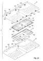
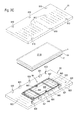
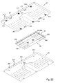
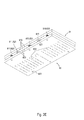
- eine Pressvorrichtung, mit Oberteil und Unterteil sowie dazwi-schen liegendem oberen Formteil und unterem Formteil, in perspektivischer Unteransicht;
- Figur 2B -
- die Pressvorrichtung gemäss
Figur 2A , oberes Formteil am Oberteil und unteres Formteil am Unterteil fixiert, und dazwi- schen liegendes unverpresstes Werkstück, in perspektivischer Unteransicht; - Figur 2C -
- die Pressvorrichtung gemäss
Figur 2B , in perspektivischer Draufsicht; - Figur 2D -
- die Pressvorrichtung gemäss
Figur 2A , oberes Formteil und unteres Formteil zusammengefügt, in perspektivischer Unteransicht; - Figur 2E -
- die Pressvorrichtung gemäss
Figur 2D , Oberteil und Unterteil zusammengefügt, in perspektivischer Unteransicht; - Figur 3A -
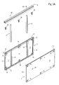
- einen kompletten Screen aus
Figur 1A , mit Anbau, in perspektivischer Explosivansicht; - Figur 3B -
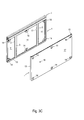
- den Aufbau gemäss
Figur 3A , in einem ersten Montageschritt, in perspektivischer Draufsicht; - Figur 3C -
- den Aufbau gemäss
Figur 3B , in einem zweiten Montageschritt, in perspektivischer Draufsicht; - Figur 3D -
- den Aufbau aus
Figur 3C , dem Tisch angenähert, in perspektivischer Draufsicht; - Figur 3E -
- den Aufbau gemäss
Figur 3D , mit am Tisch teilweise montiertem Screen, in perspektivischer Draufsicht; und - Figur 3F -
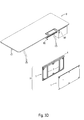
- den Aufbau gemäss
Figur 3E , mit am Tisch montiertem Screen und vom Tisch abgehobener Tischplatte, in perspektivischer Draufsicht. - Anhand der beiliegenden Zeichnungen erfolgt nachstehend die detaillierte Beschreibung eines Ausführungsbeispiels zum erfindungsgemässen Herstellungsverfahren eines Möbelteils anhand eines zur Montage an einem Tisch bestimmten Screens.
- Für die gesamte weitere Beschreibung gilt folgende Festlegung. Sind in einer Figur zum Zweck zeichnerischer Eindeutigkeit Bezugsziffern enthalten, aber im unmittelbar zugehörigen Beschreibungstext nicht erläutert, so wird auf deren Erwähnung in vorangehenden Figurenbeschreibungen Bezug genommen. Im Interesse der Übersichtlichkeit wird auf die wiederholte Bezeichnung von Bauteilen in nachfolgenden Figuren zumeist verzichtet, sofern zeichnerisch eindeutig erkennbar ist, dass es sich um "wiederkehrende" Bauteile handelt.
- Am Tisch 9 ist an der vom Benutzer abgewandten Seite ein Fertigerzeugnis 2, in Gestalt eines Screens, montiert. Ein Anbau 4, in Form einer Schiene, ist am Fertigerzeugnis 2 befestigt. Der Anbau 4 dient zum Andocken weiterer Elemente, z.B. Einhängen von Behältnissen oder Tablaren.
- Die rechteckförmige Pressvorrichtung 8 besteht im Wesentlichen aus einem Oberteil 81, einem Unterteil 82 sowie einem oberen Formteil 83 und einem unteren Formteil 84. Die Formteile 83,84 sind zum Zusammenfügen bestimmt. Im Oberteil 81 sind benachbart zu den Längskanten, zueinander beabstandet, erste Führungsorgane 810 in Form von Hülsen eingebettet. Vom Unterteil 82 erstrecken sich zu den ersten Führungsorganen 810 komplementäre zweite Führungsorgane 820 in Form von Bolzen. Die zweiten Führungsorgane 820 sind zur Aufnahme in den ersten Führungsorganen 810 bestimmt.
- Zwischen den ersten Führungsorganen 810 sind am Oberteil 81, benachbart zu den Längskanten, erste Abstandselemente 811 platziert. Am Unterteil 82 sind zwischen den zweiten Führungsorganen 820, benachbart zu den Längskanten, zweite Abstandselemente 821 platziert. Die beiden Abstandselemente 811,821 liegen sich kongruent gegenüber. Die ersten Abstandselemente 811 haben eine geringere Höhe als die zweiten Abstandselemente 821, dies ist bedingt durch die ineinander greifenden Formteile 83,84, was nachfolgend beschrieben wird.
- Im Oberteil 81 sind erste Schraubenlöcher 812 und im Unterteil 82 sind zweite Schraubenlöcher 821 vorgesehen, wobei die Schraubenlöcher 812 symmetrisch über die Fläche des Oberteils 81 verteilt liegen und zu den Schraubenlöchern 822 im Unterteil 82 deckungsgleich sind.
- Im Oberteil 81 sind in den Seitenwandungen zueinander beabstandet erste Kühlkanäle 813 eingelassen, wobei in den Seitenwandungen im Unterteil 82 zueinander beabstandet zweite Kühlkanäle 823 verlaufen.
- Das obere Formteil 83 besteht aus mehreren zusammensetzbaren oberen Segmenten 835, welche an der Oberseite, die dem Oberteil 81 gegenüberliegt, Schraubenlöcher (hier nicht sichtbar) haben, die deckungsgleich zu den ersten Schraubenlöchern 812 im Oberteil 81 sind. Je nach Anzahl der oberen Segmente 835 lässt sich ein oberes Formteil 83 in vorgesehener Dimension realisieren. Die oberen Segmente 835 bzw. das obere Formteil 83 sind über Schrauben anhand der ersten Schraubenlöcher 812 mit dem Oberteil 81 verbunden. Die oberen Segmente 835 bzw. das obere Formteil 83 besitzen eine erste Prägekontur 837 und eine zweite Prägekontur 838.
- Das untere Formteil 84 besteht aus mehreren unteren Segmenten 845, welche an der Unterseite, die dem Unterteil 82 gegenüberliegt, vierte Schraubenlöcher 842 haben, die deckungsgleich zu den zweiten Schraubenlöchern 822 im Unterteil 82 sind. Je nach Anzahl der unteren Segmente 845 lässt sich ein unteres Formteil 84 mit konzipierter Grösse realisieren. Die unteren Segmente 845 bzw. das untere Formteil 84 sind über Schrauben anhand der zweiten Schraubenlöcher 822 mit dem Unterteil 82 verbunden. Die unteren Segmente 845 bzw. das untere Formteil 84 besitzen eine dritte Prägekontur 847 und eine vierte Prägekontur 848.
- Vor dem Pressvorgang wird das Pressteil 1, welches beidseits einen Deckbezug 17 hat und dazwischen mit einer Klebeschicht 18 versehen ist, aufgeheizt, was eine Aktivierung der Klebeschicht 18 und ein leichtes Anschmelzen des Materials des Pressteils 1 bewirkt. Beim Einfügen des Pressteils 1 zwischen den Formteilen 83,84 erfolgt über das Ober- und Unterteil 81,82 durch Beschicken der jeweiligen Kühlkanäle 813,823 eine Abkühlung des Pressteils 1. Eine Seite des Deckbezugs 17 liegt auf den das untere Formteil 84 bildenden unteren Segmenten 845 sowie den Prägekonturen 847,848 auf. Beim Zusammenfahren von Oberteil 81 und Unterteil 82 werden die zweiten Führungsorgane 820 in den ersten Führungsorganen 810 gleitend aufgenommen. Die ersten Prägekonturen 837 und zweiten Prägekonturen 838 des oberen Formteils 83 sowie die dritten Prägekonturen 847 und vierten Prägekonturen 848 des unteren Formteils 84 werden auf das dazwischen eingespannte Pressteil 1 übertragen. Durch die entsprechenden Prägekonturen 837,847,838,848 erhält das zuvor rohe Pressteil 1 während des Pressvorgangs seine jeweilige Form.
- Das Pressteil 1 hat die Form, welche durch die jeweiligen zwei Formteile 83,84 vorgegeben wird und besitzt einen intensiv verpressten umlaufenden Rand 13, der zur Steifigkeit und Montage des späteren Fertigerzeugnisses 2 beiträgt. Am bearbeiteten Pressteil 1 sind ferner sich über das Pressteil 1 erstreckende Festigkeitszonen 12 entstanden, die ähnlich dem Rand 13 intensiv verpresst von geringer Materialhöhe sind und z.B. der Aufnahme von Halterungen 3 dienen. Diese Festigkeitszonen 12 tragen zur Steifigkeit des späteren Fertigerzeugnisses 2 bei. In den Randbereichen sind verdichtete Formzonen 14 als Mulden für Verschraubungen entstanden. Die übrigen Areale am Pressteil 1 sind nur geringfügig verdichtet und weisen daher eine deutlich grössere Dicke auf, um als Dämpfungszonen 11 schallschluckend zu wirken sowie das Einstechen von Pins zu ermöglichen.
- Der als beispielhaftes Fertigerzeugnis 2 hergestellte Screen besteht aus zwei miteinander kongruenten Pressteilen 1. Zur Montage wird der schienenartige Anbau 4 mit den Verbindern 30 und den strebenförmigen Halterungen 3 zusammengefügt. Anschliessend wird die Einheit aus Anbau 4, Verbindern 30 und Halterungen 3 so mit den Pressteilen 1 verbunden, dass der Anbau 4 auf der Oberseite beider aneinander gefügter Pressteile 1 zu liegen kommt, die Verbinder 30 in die Formzonen 14 für die spätere Verschraubung 19 ragen und die Halterungen 3 in den dafür geformten Festigkeitszonen 12 sitzen. Schrauben 49 dienen der Verbindung zwischen dem Anbau 4 und den Halterungen 3. Im weiteren Montageablauf wird das mit dem Anbau 4, den Verbindern 30 und den Halterungen 3 versehene Pressteil 1 an den Haltern 90 des Tisches 9 verschraubt. Schliesslich wird das zweite bisher lose geformte Pressteil 1 an das zuvor am Tisch 9 montierte Pressteil 1 aufgesetzt.
Claims (7)
- Verfahren zur Herstellung eines Pressteils (1) in Form eines Möbelteils als Fertigerzeugnis (2) oder als Komponente für ein Fertigerzeugnis (2), gekennzeichnet durch folgende Schritte:a) ein pressfähiges Ausgangswerkstück (1) wird bereitgestellt; undb) das Ausgangswerkstück (1) wird in einer Pressvorrichtung (8) mit einem ersten Formteil (83) und darin vorhandenen Prägekonturen (837,838) sowie einem zweiten Formteil (84) mit darin vorhandenen Prägekonturen (847,848) gepresst, so dass am bearbeiteten Pressteil (1) entstehen:c) intensiv verdichtete Festigkeitszonen (12) zur Erzeugung einer Steifigkeit des Pressteils (1); undd) nicht oder nur geringfügig verdichtete Dämpfungszonen (11) zur Erzeugung intensiv schallschluckender Areale am Pressteil (1).
- Verfahren nach Anspruch 1, dadurch gekennzeichnet, dass die Prägekonturen (838,848) an den Formteilen (83,84) auch zur Herstellung eines intensiv verdichteten Randes (13) am Pressteil (1) zu dessen Steifigkeit genutzt werden.
- Verfahren nach einem der Ansprüche 1 und 2, dadurch gekennzeichnet, dass das Ausgangswerkstück (1) im Wesentlichen aus Stofffasern besteht, z.B. einer Mischung aus Woll- und synthetischen Fasern.
- Verfahren nach einem der Ansprüche 1 bis 3, dadurch gekennzeichnet, dass das Ausgangswerkstück (1) vor dem Verpressen mit einer Klebeschicht (18) und äusserlich mit einem darüber gelegten Deckbezug (17) versehen wird.
- Verfahren nach einem der Ansprüche 1 bis 4, dadurch gekennzeichnet, dass vor dem Verpressen das Ausgangswerkstück (1) zunächst aufgeheizt wird, um ein anfängliches Aufschmelzen des Fasermaterials zu erreichen, und beim Verpressen eine Abkühlung erfolgt.
- Verfahren nach einem der Ansprüche 1 bis 5, dadurch gekennzeichnet, dass die Formteile (83,84) aus Segmenten (835,845) zusammensetzbar sind, um Pressteile (1) verschiedener Dimensionen und mit verschiedenen Anordnungen der Festigkeitszonen (12) und Dämpfungszonen (11) sowie optionalen Rändern (13) und Formzonen (14) herzustellen.
- Verfahren nach einem der Ansprüche 1 bis 6, dadurch gekennzeichnet, dass die Pressvorrichtung (8) ferner ein Oberteil (81) und ein Unterteil (82) umfasst, auf das jeweils eines der Formteile (83,84) aufgespannt ist, und dass das Oberteil (81) und das Unterteil (82) zur Abkühlung genutzt werden.
Applications Claiming Priority (1)
| Application Number | Priority Date | Filing Date | Title |
|---|---|---|---|
| CH01801/10A CH704027A2 (de) | 2010-10-26 | 2010-10-26 | Verfahren zur Herstellung eines Möbelteils. |
Publications (3)
| Publication Number | Publication Date |
|---|---|
| EP2447032A2 true EP2447032A2 (de) | 2012-05-02 |
| EP2447032A3 EP2447032A3 (de) | 2017-03-22 |
| EP2447032B1 EP2447032B1 (de) | 2020-07-08 |
Family
ID=45023769
Family Applications (1)
| Application Number | Title | Priority Date | Filing Date |
|---|---|---|---|
| EP11405341.6A Active EP2447032B1 (de) | 2010-10-26 | 2011-10-24 | Verfahren zur Herstellung eines Möbelteils |
Country Status (2)
| Country | Link |
|---|---|
| EP (1) | EP2447032B1 (de) |
| CH (1) | CH704027A2 (de) |
Family Cites Families (6)
| Publication number | Priority date | Publication date | Assignee | Title |
|---|---|---|---|---|
| CH539505A (fr) * | 1971-07-28 | 1973-07-31 | Matec Holding | Elément autoporteur de garnissage et procédé de fabrication de cet élément |
| US4418031A (en) * | 1981-04-06 | 1983-11-29 | Van Dresser Corporation | Moldable fibrous mat and method of making the same |
| US4474846A (en) * | 1981-04-06 | 1984-10-02 | Van Dresser Corporation | Moldable fibrous mat and product molded therefrom |
| JPH0681704U (ja) * | 1993-04-30 | 1994-11-22 | 三井木材工業株式会社 | 包装用緩衝性固定材 |
| JP2002316332A (ja) * | 2001-04-20 | 2002-10-29 | Kasai Kogyo Co Ltd | 車両用吸音材の成形方法及び成形用金型 |
| US8043542B2 (en) * | 2007-02-19 | 2011-10-25 | Quadrant Plastic Composites, AG | Method for the production of fiber-reinforced polypropylene molded parts containing pores |
-
2010
- 2010-10-26 CH CH01801/10A patent/CH704027A2/de not_active Application Discontinuation
-
2011
- 2011-10-24 EP EP11405341.6A patent/EP2447032B1/de active Active
Non-Patent Citations (1)
| Title |
|---|
| None |
Also Published As
| Publication number | Publication date |
|---|---|
| EP2447032A3 (de) | 2017-03-22 |
| EP2447032B1 (de) | 2020-07-08 |
| CH704027A2 (de) | 2012-04-30 |
Similar Documents
| Publication | Publication Date | Title |
|---|---|---|
| DE69110506T2 (de) | Pressform zum Formen von Verbundmaterialstrukturen. | |
| DE8307078U1 (de) | Vorrichtung zur herstellung von formlingen aus beton oder dergleichen | |
| DE10161929A1 (de) | Platte aus einem planebenen Kern und mit diesem verbundenen gewölbten Teilen und Verfahren zur Herstellung einer derartigen Platte | |
| DE102010060742A1 (de) | Form zur Herstellung von Betonformsteinen | |
| EP1080879B1 (de) | Heissverformbare Pressstoffplatte | |
| EP1655122B1 (de) | Verfahren zum Hinterspritzen, Hinterpressen oder Quellflussprägen und entsprechendes Formwerkzeug | |
| DE3343330C2 (de) | ||
| WO2013167234A1 (de) | Verfahren zum wenigstens bereichsweisen konsolidieren eines vorformlings zur herstellung eines formteils in einem formwerkzeug | |
| DE3784474T2 (de) | Fliesen. | |
| DE102012013538B4 (de) | Verfahren zur Herstellung von Sandwichelementen | |
| EP0177628B1 (de) | Verfahren und Vorrichtung zur Herstellung von gepressten Profilkörpern | |
| EP2447032B1 (de) | Verfahren zur Herstellung eines Möbelteils | |
| DE102005057550A1 (de) | Verfahren und Vorrichtung zur Herstellung einer Leichtbauplatte und Leichtbauplatte | |
| DE3636587A1 (de) | Verfahren zum herstellen eines furnierwerkstueckes mit ausschnitt sowie pressstanzwerkzeug zu seiner durchfuehrung | |
| EP0115552B1 (de) | Vorrichtung zur Herstellung von Formteilen | |
| DE112012006494T5 (de) | Verpackungskiste und ein Verfahren zur Herstellung derselben | |
| DE102012106936A1 (de) | Integrierte Kontaktheizung für thermoplastisch gebundene Matten im Spritzgießwerkzeug | |
| WO2010031786A1 (de) | Unterlagsplatte zur auflage von erzeugnissen während deren herstellung sowie zur lagerung derselben in einem regal o.dgl. | |
| EP1398144B1 (de) | Laminiertes Blendenelement | |
| DE4444906C2 (de) | Mehrschichtige Gartentischplatte | |
| DE3742008A1 (de) | Verfahren zur herstellung einer arbeitsplatte und arbeitsplatte | |
| EP0555499A1 (de) | Verfahren zur Herstellung einer aus Holz bestehenden Möbelfrontplatte sowie nach diesem Verfahren hergestellte Möbelfrontplatte | |
| AT288681B (de) | Verfahren und Preßform zur Herstellung von mit Zierkörpern od.dgl. besetzten Platten aus thermoplastischem Material | |
| DE3128774C2 (de) | ||
| DE1653312B2 (de) | Verwendung einer Plattenpresse |
Legal Events
| Date | Code | Title | Description |
|---|---|---|---|
| PUAI | Public reference made under article 153(3) epc to a published international application that has entered the european phase |
Free format text: ORIGINAL CODE: 0009012 |
|
| AK | Designated contracting states |
Kind code of ref document: A2 Designated state(s): AL AT BE BG CH CY CZ DE DK EE ES FI FR GB GR HR HU IE IS IT LI LT LU LV MC MK MT NL NO PL PT RO RS SE SI SK SM TR |
|
| AX | Request for extension of the european patent |
Extension state: BA ME |
|
| PUAL | Search report despatched |
Free format text: ORIGINAL CODE: 0009013 |
|
| AK | Designated contracting states |
Kind code of ref document: A3 Designated state(s): AL AT BE BG CH CY CZ DE DK EE ES FI FR GB GR HR HU IE IS IT LI LT LU LV MC MK MT NL NO PL PT RO RS SE SI SK SM TR |
|
| AX | Request for extension of the european patent |
Extension state: BA ME |
|
| RIC1 | Information provided on ipc code assigned before grant |
Ipc: B29C 43/02 20060101AFI20170216BHEP Ipc: B27N 3/04 20060101ALI20170216BHEP Ipc: B29K 511/10 20060101ALN20170216BHEP Ipc: B29C 43/36 20060101ALN20170216BHEP Ipc: B27N 3/00 20060101ALI20170216BHEP Ipc: B27N 3/20 20060101ALN20170216BHEP Ipc: B29L 31/44 20060101ALN20170216BHEP |
|
| STAA | Information on the status of an ep patent application or granted ep patent |
Free format text: STATUS: REQUEST FOR EXAMINATION WAS MADE |
|
| 17P | Request for examination filed |
Effective date: 20170921 |
|
| RBV | Designated contracting states (corrected) |
Designated state(s): AL AT BE BG CH CY CZ DE DK EE ES FI FR GB GR HR HU IE IS IT LI LT LU LV MC MK MT NL NO PL PT RO RS SE SI SK SM TR |
|
| STAA | Information on the status of an ep patent application or granted ep patent |
Free format text: STATUS: EXAMINATION IS IN PROGRESS |
|
| 17Q | First examination report despatched |
Effective date: 20180719 |
|
| REG | Reference to a national code |
Ref country code: DE Ref legal event code: R079 Ref document number: 502011016779 Country of ref document: DE Free format text: PREVIOUS MAIN CLASS: B29C0044040000 Ipc: B29C0043000000 |
|
| GRAP | Despatch of communication of intention to grant a patent |
Free format text: ORIGINAL CODE: EPIDOSNIGR1 |
|
| STAA | Information on the status of an ep patent application or granted ep patent |
Free format text: STATUS: GRANT OF PATENT IS INTENDED |
|
| RIC1 | Information provided on ipc code assigned before grant |
Ipc: B27N 3/04 20060101ALI20191220BHEP Ipc: B29K 511/10 20060101ALN20191220BHEP Ipc: B27N 3/20 20060101ALN20191220BHEP Ipc: B29L 31/44 20060101ALN20191220BHEP Ipc: B29C 43/36 20060101ALN20191220BHEP Ipc: B27N 3/00 20060101ALI20191220BHEP Ipc: B29C 43/02 20060101ALI20191220BHEP Ipc: B29C 43/00 20060101AFI20191220BHEP |
|
| RIN1 | Information on inventor provided before grant (corrected) |
Inventor name: KELLER, STEFAN |
|
| INTG | Intention to grant announced |
Effective date: 20200116 |
|
| GRAS | Grant fee paid |
Free format text: ORIGINAL CODE: EPIDOSNIGR3 |
|
| GRAA | (expected) grant |
Free format text: ORIGINAL CODE: 0009210 |
|
| STAA | Information on the status of an ep patent application or granted ep patent |
Free format text: STATUS: THE PATENT HAS BEEN GRANTED |
|
| AK | Designated contracting states |
Kind code of ref document: B1 Designated state(s): AL AT BE BG CH CY CZ DE DK EE ES FI FR GB GR HR HU IE IS IT LI LT LU LV MC MK MT NL NO PL PT RO RS SE SI SK SM TR |
|
| REG | Reference to a national code |
Ref country code: GB Ref legal event code: FG4D Free format text: NOT ENGLISH |
|
| REG | Reference to a national code |
Ref country code: CH Ref legal event code: EP Ref country code: AT Ref legal event code: REF Ref document number: 1287972 Country of ref document: AT Kind code of ref document: T Effective date: 20200715 |
|
| REG | Reference to a national code |
Ref country code: DE Ref legal event code: R096 Ref document number: 502011016779 Country of ref document: DE |
|
| REG | Reference to a national code |
Ref country code: IE Ref legal event code: FG4D Free format text: LANGUAGE OF EP DOCUMENT: GERMAN |
|
| REG | Reference to a national code |
Ref country code: CH Ref legal event code: NV Representative=s name: LATSCHA SCHOELLHORN PARTNER AG, CH |
|
| REG | Reference to a national code |
Ref country code: NL Ref legal event code: FP |
|
| PGFP | Annual fee paid to national office [announced via postgrant information from national office to epo] |
Ref country code: NL Payment date: 20200909 Year of fee payment: 10 Ref country code: FR Payment date: 20200929 Year of fee payment: 10 |
|
| REG | Reference to a national code |
Ref country code: LT Ref legal event code: MG4D |
|
| PGFP | Annual fee paid to national office [announced via postgrant information from national office to epo] |
Ref country code: CH Payment date: 20200915 Year of fee payment: 10 |
|
| PG25 | Lapsed in a contracting state [announced via postgrant information from national office to epo] |
Ref country code: BG Free format text: LAPSE BECAUSE OF FAILURE TO SUBMIT A TRANSLATION OF THE DESCRIPTION OR TO PAY THE FEE WITHIN THE PRESCRIBED TIME-LIMIT Effective date: 20201008 Ref country code: SE Free format text: LAPSE BECAUSE OF FAILURE TO SUBMIT A TRANSLATION OF THE DESCRIPTION OR TO PAY THE FEE WITHIN THE PRESCRIBED TIME-LIMIT Effective date: 20200708 Ref country code: GR Free format text: LAPSE BECAUSE OF FAILURE TO SUBMIT A TRANSLATION OF THE DESCRIPTION OR TO PAY THE FEE WITHIN THE PRESCRIBED TIME-LIMIT Effective date: 20201009 Ref country code: HR Free format text: LAPSE BECAUSE OF FAILURE TO SUBMIT A TRANSLATION OF THE DESCRIPTION OR TO PAY THE FEE WITHIN THE PRESCRIBED TIME-LIMIT Effective date: 20200708 Ref country code: NO Free format text: LAPSE BECAUSE OF FAILURE TO SUBMIT A TRANSLATION OF THE DESCRIPTION OR TO PAY THE FEE WITHIN THE PRESCRIBED TIME-LIMIT Effective date: 20201008 Ref country code: LT Free format text: LAPSE BECAUSE OF FAILURE TO SUBMIT A TRANSLATION OF THE DESCRIPTION OR TO PAY THE FEE WITHIN THE PRESCRIBED TIME-LIMIT Effective date: 20200708 Ref country code: PT Free format text: LAPSE BECAUSE OF FAILURE TO SUBMIT A TRANSLATION OF THE DESCRIPTION OR TO PAY THE FEE WITHIN THE PRESCRIBED TIME-LIMIT Effective date: 20201109 Ref country code: ES Free format text: LAPSE BECAUSE OF FAILURE TO SUBMIT A TRANSLATION OF THE DESCRIPTION OR TO PAY THE FEE WITHIN THE PRESCRIBED TIME-LIMIT Effective date: 20200708 Ref country code: FI Free format text: LAPSE BECAUSE OF FAILURE TO SUBMIT A TRANSLATION OF THE DESCRIPTION OR TO PAY THE FEE WITHIN THE PRESCRIBED TIME-LIMIT Effective date: 20200708 |
|
| PGFP | Annual fee paid to national office [announced via postgrant information from national office to epo] |
Ref country code: DE Payment date: 20200909 Year of fee payment: 10 Ref country code: CZ Payment date: 20200910 Year of fee payment: 10 |
|
| PG25 | Lapsed in a contracting state [announced via postgrant information from national office to epo] |
Ref country code: LV Free format text: LAPSE BECAUSE OF FAILURE TO SUBMIT A TRANSLATION OF THE DESCRIPTION OR TO PAY THE FEE WITHIN THE PRESCRIBED TIME-LIMIT Effective date: 20200708 Ref country code: RS Free format text: LAPSE BECAUSE OF FAILURE TO SUBMIT A TRANSLATION OF THE DESCRIPTION OR TO PAY THE FEE WITHIN THE PRESCRIBED TIME-LIMIT Effective date: 20200708 Ref country code: PL Free format text: LAPSE BECAUSE OF FAILURE TO SUBMIT A TRANSLATION OF THE DESCRIPTION OR TO PAY THE FEE WITHIN THE PRESCRIBED TIME-LIMIT Effective date: 20200708 Ref country code: IS Free format text: LAPSE BECAUSE OF FAILURE TO SUBMIT A TRANSLATION OF THE DESCRIPTION OR TO PAY THE FEE WITHIN THE PRESCRIBED TIME-LIMIT Effective date: 20201108 |
|
| REG | Reference to a national code |
Ref country code: DE Ref legal event code: R097 Ref document number: 502011016779 Country of ref document: DE |
|
| PG25 | Lapsed in a contracting state [announced via postgrant information from national office to epo] |
Ref country code: RO Free format text: LAPSE BECAUSE OF FAILURE TO SUBMIT A TRANSLATION OF THE DESCRIPTION OR TO PAY THE FEE WITHIN THE PRESCRIBED TIME-LIMIT Effective date: 20200708 Ref country code: SM Free format text: LAPSE BECAUSE OF FAILURE TO SUBMIT A TRANSLATION OF THE DESCRIPTION OR TO PAY THE FEE WITHIN THE PRESCRIBED TIME-LIMIT Effective date: 20200708 Ref country code: IT Free format text: LAPSE BECAUSE OF FAILURE TO SUBMIT A TRANSLATION OF THE DESCRIPTION OR TO PAY THE FEE WITHIN THE PRESCRIBED TIME-LIMIT Effective date: 20200708 Ref country code: EE Free format text: LAPSE BECAUSE OF FAILURE TO SUBMIT A TRANSLATION OF THE DESCRIPTION OR TO PAY THE FEE WITHIN THE PRESCRIBED TIME-LIMIT Effective date: 20200708 Ref country code: DK Free format text: LAPSE BECAUSE OF FAILURE TO SUBMIT A TRANSLATION OF THE DESCRIPTION OR TO PAY THE FEE WITHIN THE PRESCRIBED TIME-LIMIT Effective date: 20200708 |
|
| PLBE | No opposition filed within time limit |
Free format text: ORIGINAL CODE: 0009261 |
|
| STAA | Information on the status of an ep patent application or granted ep patent |
Free format text: STATUS: NO OPPOSITION FILED WITHIN TIME LIMIT |
|
| PG25 | Lapsed in a contracting state [announced via postgrant information from national office to epo] |
Ref country code: AL Free format text: LAPSE BECAUSE OF FAILURE TO SUBMIT A TRANSLATION OF THE DESCRIPTION OR TO PAY THE FEE WITHIN THE PRESCRIBED TIME-LIMIT Effective date: 20200708 |
|
| 26N | No opposition filed |
Effective date: 20210409 |
|
| GBPC | Gb: european patent ceased through non-payment of renewal fee |
Effective date: 20201024 |
|
| PG25 | Lapsed in a contracting state [announced via postgrant information from national office to epo] |
Ref country code: LU Free format text: LAPSE BECAUSE OF NON-PAYMENT OF DUE FEES Effective date: 20201024 Ref country code: MC Free format text: LAPSE BECAUSE OF FAILURE TO SUBMIT A TRANSLATION OF THE DESCRIPTION OR TO PAY THE FEE WITHIN THE PRESCRIBED TIME-LIMIT Effective date: 20200708 Ref country code: SK Free format text: LAPSE BECAUSE OF FAILURE TO SUBMIT A TRANSLATION OF THE DESCRIPTION OR TO PAY THE FEE WITHIN THE PRESCRIBED TIME-LIMIT Effective date: 20200708 |
|
| REG | Reference to a national code |
Ref country code: BE Ref legal event code: MM Effective date: 20201031 |
|
| PG25 | Lapsed in a contracting state [announced via postgrant information from national office to epo] |
Ref country code: SI Free format text: LAPSE BECAUSE OF FAILURE TO SUBMIT A TRANSLATION OF THE DESCRIPTION OR TO PAY THE FEE WITHIN THE PRESCRIBED TIME-LIMIT Effective date: 20200708 Ref country code: GB Free format text: LAPSE BECAUSE OF NON-PAYMENT OF DUE FEES Effective date: 20201024 Ref country code: BE Free format text: LAPSE BECAUSE OF NON-PAYMENT OF DUE FEES Effective date: 20201031 |
|
| PG25 | Lapsed in a contracting state [announced via postgrant information from national office to epo] |
Ref country code: IE Free format text: LAPSE BECAUSE OF NON-PAYMENT OF DUE FEES Effective date: 20201024 |
|
| REG | Reference to a national code |
Ref country code: AT Ref legal event code: MM01 Ref document number: 1287972 Country of ref document: AT Kind code of ref document: T Effective date: 20201024 |
|
| PG25 | Lapsed in a contracting state [announced via postgrant information from national office to epo] |
Ref country code: AT Free format text: LAPSE BECAUSE OF NON-PAYMENT OF DUE FEES Effective date: 20201024 |
|
| REG | Reference to a national code |
Ref country code: DE Ref legal event code: R119 Ref document number: 502011016779 Country of ref document: DE |
|
| REG | Reference to a national code |
Ref country code: CH Ref legal event code: PL |
|
| PG25 | Lapsed in a contracting state [announced via postgrant information from national office to epo] |
Ref country code: TR Free format text: LAPSE BECAUSE OF FAILURE TO SUBMIT A TRANSLATION OF THE DESCRIPTION OR TO PAY THE FEE WITHIN THE PRESCRIBED TIME-LIMIT Effective date: 20200708 Ref country code: MT Free format text: LAPSE BECAUSE OF FAILURE TO SUBMIT A TRANSLATION OF THE DESCRIPTION OR TO PAY THE FEE WITHIN THE PRESCRIBED TIME-LIMIT Effective date: 20200708 Ref country code: CY Free format text: LAPSE BECAUSE OF FAILURE TO SUBMIT A TRANSLATION OF THE DESCRIPTION OR TO PAY THE FEE WITHIN THE PRESCRIBED TIME-LIMIT Effective date: 20200708 |
|
| REG | Reference to a national code |
Ref country code: NL Ref legal event code: MM Effective date: 20211101 |
|
| PG25 | Lapsed in a contracting state [announced via postgrant information from national office to epo] |
Ref country code: MK Free format text: LAPSE BECAUSE OF FAILURE TO SUBMIT A TRANSLATION OF THE DESCRIPTION OR TO PAY THE FEE WITHIN THE PRESCRIBED TIME-LIMIT Effective date: 20200708 |
|
| PG25 | Lapsed in a contracting state [announced via postgrant information from national office to epo] |
Ref country code: NL Free format text: LAPSE BECAUSE OF NON-PAYMENT OF DUE FEES Effective date: 20211101 Ref country code: DE Free format text: LAPSE BECAUSE OF NON-PAYMENT OF DUE FEES Effective date: 20220503 Ref country code: CZ Free format text: LAPSE BECAUSE OF NON-PAYMENT OF DUE FEES Effective date: 20211024 |
|
| PG25 | Lapsed in a contracting state [announced via postgrant information from national office to epo] |
Ref country code: LI Free format text: LAPSE BECAUSE OF NON-PAYMENT OF DUE FEES Effective date: 20211031 Ref country code: CH Free format text: LAPSE BECAUSE OF NON-PAYMENT OF DUE FEES Effective date: 20211031 |
|
| PG25 | Lapsed in a contracting state [announced via postgrant information from national office to epo] |
Ref country code: FR Free format text: LAPSE BECAUSE OF NON-PAYMENT OF DUE FEES Effective date: 20211031 |