EP2446972B1 - Ausklappsprinkler mit einem Sensor zur Erkennung der Position oder Drehung - Google Patents
Ausklappsprinkler mit einem Sensor zur Erkennung der Position oder Drehung Download PDFInfo
- Publication number
- EP2446972B1 EP2446972B1 EP11193501.1A EP11193501A EP2446972B1 EP 2446972 B1 EP2446972 B1 EP 2446972B1 EP 11193501 A EP11193501 A EP 11193501A EP 2446972 B1 EP2446972 B1 EP 2446972B1
- Authority
- EP
- European Patent Office
- Prior art keywords
- nozzle assembly
- sprinkler
- case
- nozzle
- shaped member
- Prior art date
- Legal status (The legal status is an assumption and is not a legal conclusion. Google has not performed a legal analysis and makes no representation as to the accuracy of the status listed.)
- Active
Links
Images


Classifications
-
- B—PERFORMING OPERATIONS; TRANSPORTING
- B05—SPRAYING OR ATOMISING IN GENERAL; APPLYING FLUENT MATERIALS TO SURFACES, IN GENERAL
- B05B—SPRAYING APPARATUS; ATOMISING APPARATUS; NOZZLES
- B05B3/00—Spraying or sprinkling apparatus with moving outlet elements or moving deflecting elements
- B05B3/02—Spraying or sprinkling apparatus with moving outlet elements or moving deflecting elements with rotating elements
- B05B3/04—Spraying or sprinkling apparatus with moving outlet elements or moving deflecting elements with rotating elements driven by the liquid or other fluent material discharged, e.g. the liquid actuating a motor before passing to the outlet
-
- B—PERFORMING OPERATIONS; TRANSPORTING
- B05—SPRAYING OR ATOMISING IN GENERAL; APPLYING FLUENT MATERIALS TO SURFACES, IN GENERAL
- B05B—SPRAYING APPARATUS; ATOMISING APPARATUS; NOZZLES
- B05B15/00—Details of spraying plant or spraying apparatus not otherwise provided for; Accessories
- B05B15/70—Arrangements for moving spray heads automatically to or from the working position
- B05B15/72—Arrangements for moving spray heads automatically to or from the working position using hydraulic or pneumatic means
- B05B15/74—Arrangements for moving spray heads automatically to or from the working position using hydraulic or pneumatic means driven by the discharged fluid
-
- B—PERFORMING OPERATIONS; TRANSPORTING
- B05—SPRAYING OR ATOMISING IN GENERAL; APPLYING FLUENT MATERIALS TO SURFACES, IN GENERAL
- B05B—SPRAYING APPARATUS; ATOMISING APPARATUS; NOZZLES
- B05B3/00—Spraying or sprinkling apparatus with moving outlet elements or moving deflecting elements
- B05B3/02—Spraying or sprinkling apparatus with moving outlet elements or moving deflecting elements with rotating elements
- B05B3/10—Spraying or sprinkling apparatus with moving outlet elements or moving deflecting elements with rotating elements discharging over substantially the whole periphery of the rotating member
- B05B3/1085—Spraying or sprinkling apparatus with moving outlet elements or moving deflecting elements with rotating elements discharging over substantially the whole periphery of the rotating member with means for detecting or controlling the rotational speed
-
- Y—GENERAL TAGGING OF NEW TECHNOLOGICAL DEVELOPMENTS; GENERAL TAGGING OF CROSS-SECTIONAL TECHNOLOGIES SPANNING OVER SEVERAL SECTIONS OF THE IPC; TECHNICAL SUBJECTS COVERED BY FORMER USPC CROSS-REFERENCE ART COLLECTIONS [XRACs] AND DIGESTS
- Y10—TECHNICAL SUBJECTS COVERED BY FORMER USPC
- Y10S—TECHNICAL SUBJECTS COVERED BY FORMER USPC CROSS-REFERENCE ART COLLECTIONS [XRACs] AND DIGESTS
- Y10S239/00—Fluid sprinkling, spraying, and diffusing
- Y10S239/11—Magnets
Definitions
- This relates to irrigation system components, and more specifically, to irrigation rotor sprinklers.
- Pop-up irrigation rotor sprinklers are known in the art and are especially useful where it is desired that they be placed in the ground so that they are at ground level when not in use.
- a tubular riser is mounted within a generally cylindrical upright sprinkler housing or case having an open upper end.
- a spray head carrying one or more spray nozzles is mounted at an upper end of the riser and supports a housing cap or cover to close the housing when the sprinkler is not in operation.
- the spray head and riser are spring-retracted into the sprinkler case so that they are below ground level.
- the riser is extended upwardly to shift the spray head to an elevated spraying position spaced above the sprinkler case and the ground.
- the water under pressure flows through a vertically oriented passage in the riser to the spray head which includes one or more appropriately shaped spray nozzles for projecting one or more streams of water radially outwardly over a surrounding terrain area and vegetation.
- a rotary drive mechanism is provided within the sprinkler case for rotatably driving the spray head through continuous full circle revolutions, or alternately, back and forth within a predetermined part-circle path, to sweep the projected water stream over a selected target terrain area.
- the rotary drive mechanism comprises a water-driven turbine which is driven by the pressurized water supplied to the sprinkler case. This turbine rotatably drives a speed reduction gear drive transmission coupled in turn to the rotary mounted spray head.
- adjustable means are normally provided to cause spay head rotation to reverse upon reaching a predetermined, part-circle path of motion, or to achieve continuous, full-circle rotation, if desired.
- US 2004/0135001 discloses an irrigation sprinkler forming the basis of claim 1.
- Embodiments of the invention provide a new and improved rotary sprinkler that includes a relatively simple, inexpensive, yet reliable assembly for automatically and accurately indicating the operating condition of the sprinkler and which can provide the information to a central control station for alerting an operator of any potential sprinkler irrigation problems. More specifically, embodiments of the invention employ a Hall-effect sensor that is adapted to detect the position or rotation of the sprinkler in order to provide a signal indicative of the sprinkler condition and rate of rotation. This signal can be transmitted, either wirelessly or via conductors, to a central control station for automatic response or observation by the system operator.
- a sprinkler nozzle assembly is rotatable and has one or more magnets coupled or connected to the assembly so that they synchronously rotate with it.
- a sensor unit is mounted adjacent to the magnets and provides electrical signals in response to the magnetic fields produced by the rotating magnets. These electrical signals are used to provide information as to both the direction of rotation and the speed of rotation of the nozzle assembly. This information is transmitted either wirelessly or via wires to a computer or monitor at a central location where a user can easily monitor the operation of a plurality of units.
- a first magnet is connected to the nozzle assembly and adapted to produce a first magnetic field, wherein the first magnet rotates in response to the rotation of the nozzle assembly.
- a sensor unit comprising a Hall-effect sensor is mounted adjacent to the nozzle assembly for detecting the first magnetic field when the nozzle assembly is rotating.
- a second magnet is connected to the nozzle assembly and adapted to produce a second magnetic field that rotates in response to the rotation of the nozzle assembly.
- the sensor unit comprises two Hall-effect sensors, and detects the second magnetic field when the nozzle assembly is rotating. Additionally the sensor unit detects the direction of rotation and the speed of rotation of the nozzle assembly.
- FIG. 1 is an exploded parts diagram of an irrigation sprinkler according to one embodiment of the invention
- FIG. 2 is a cross-sectional view of the irrigation sprinkler of FIG. 1 ;
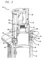
- FIG. 3 is a perspective, cut-away view of the irrigation sprinkler of FIG. 1 ;
- FIG. 4 is an enlarged cross-sectional view of a portion of FIG. 2 ;
- FIG. 5a is a top plan view of a rotating ring of the irrigation sprinkler of FIG. 1 ;
- FIG. 5b is a perspective view of the rotating ring of FIG. 5a .
- an irrigation sprinkler that includes a rotatable nozzle assembly with a plurality of magnets coupled or connected to the nozzle assembly so that they synchronously rotate with it.
- a stationary sensor unit is mounted adjacent to the magnets and provides electrical signals in response to the magnetic fields produced by the rotating magnets.
- the sensor unit includes two Hall-effect sensors located in one housing.
- a magnetic field associated with one magnet sweeps past one of the Hall-effect sensors, and then sweeps past the other Hall-effect sensor, the direction of rotation can be determined.
- a magnetic field associated with one magnet sweeps past one Hall-effect sensor, and then a second magnetic field associated with a second magnet sweeps past the same Hall-effect sensor, the time that elapses between these events can be measured and a speed of rotation calculated.
- the sensor unit and associated electronics can provide a signal indicative of the direction and speed of rotation for each irrigation sprinkler which signals can then be transmitted, either wirelessly or via wires, to a computer or monitor or other electronic device having a processor located remotely from each irrigation sprinkler. This enables a user who is in a central location to monitor the operation of many, widely-dispersed irrigation sprinklers without having to travel in the field for monitoring purposes.
- FIG. 1 is an exploded parts diagram of an irrigation sprinkler 10 in accordance with one embodiment of the invention.
- the irrigation sprinkler 10 comprises a riser 14 having a tubular upper portion 32 and a tapered O-ring seal 34 extending around a lower end of the tubular upper portion 32.
- the riser 14 is adapted to fit within a case 12 and to move vertically relative to the case from a lower inoperative position to an upper operative position in response to water pressure.
- a nozzle base 16 is adapted to mate with the tubular upper portion 32 of the riser 14. Thus when the riser 14 moves vertically, it carries the nozzle base 16 along with it.
- the nozzle base 16 includes a plurality of vertical grooves 36 formed on the exterior surface of the base 16, each of which terminates in a ledge 38 located near the lower end of the nozzle base 16.
- a bearing guide 18, a lower snap ring 20, a rotating ring 22, and an upper snap ring 24 are each adapted to surround the nozzle base 16 and fit within the case 12.
- the bearing guide 18, the lower snap ring 20, and the upper snap ring 24 are adapted to rigidly seat within the case 12, whereas the rotating ring 22 is adapted to "float" within the case 12.
- a nozzle housing 26 mates with the nozzle base 16 (thereby forming a nozzle assembly), and includes vertical nozzle housing grooves 40 formed on the exterior surface of the nozzle housing 26 that are aligned with the grooves 36 in the nozzle base 16.
- the nozzle base 16 and nozzle housing 26 rotate with respect to the riser 14 and the case 12.
- a rubber collar 28 is seated at the top of the case 12 and surrounds the nozzle housing 26. This serves to prevent debris from entering the case assembly.
- a sensor unit 30 is attached to the exterior of the case 12, and located near its upper portion.
- FIG. 1 shows the nozzle base 16 and the nozzle housing 26 as separate components that are adapted to mate with one another, an alternative embodiment could include these two components being constructed as a single part, thereby forming a unitary nozzle assembly.
- FIGs. 2 , 3 , and 4 show cross-sectional and cut-away views of the irrigation sprinkler 10 when in the fully extended position.
- the case 12 has a case wall 37 constructed of plastic and defining a generally hollow case interior 39.
- the bearing guide 18 is seated within the case interior 39 and has a bottom surface 42 that is positioned to abut the O-ring 34 that is seated on the riser 14 when the riser 14 is in the fully extended position.
- the bearing guide 18 therefore acts as a "stop" for the riser 14 thereby preventing it from extending upwardly any further. Additionally, the bearing guide 18 serves to seal irrigation water to the areas below the bearing guide 18 and prevent or minimize water from entering the regions of the sprinkler 10 located above the bearing guide 18.
- the lower snap ring 20 is rigidly seated in the case interior 39 and is located to contact or abut an upper surface 44 of the bearing guide 18 thereby maintaining the bearing guide 18 in position so that it may seal the compartment below.
- the rotating ring 22 is adapted to fit within the case 12 and surround the nozzle base 16 and tubular upper portion 32 of the riser 14.
- the rotating ring 22 is constructed of plastic and sits on a seating surface or flange 46 of the interior of the case 12 when the riser 14 and the nozzle base 38 are in a relatively lower vertical position. However, when the riser 14 and nozzle base 16 move vertically upward, they slide vertically relative to the rotating ring 22 which remains in a relatively stationary, vertical position. As shown in FIGs.
- the nozzle base ledge 38 abuts the rotating ring 22 and raises it off of the case flange 46, thereby creating a small gap 48 between the rotating ring 22 and the case flange 46.
- the rotating ring 22 is rotatably coupled to the nozzle base 16 so that when the nozzle base 16 rotates, the ring 22 synchronously rotates with it. Because the rotating ring 22 is lifted off of the case flange 46 when the nozzle base 16 is extended, the ring 22 "floats" as it is rotating thereby reducing or eliminating friction and drag between the case 12, the rotating ring 22, and the nozzle base 16 as it rotates.
- a plurality of magnets 50 are attached to the rotating ring 22 by embedding them within the ring 22 and are disposed at a radially outward portion of the ring 22.
- the sensor unit 30 is mounted on the outside of the plastic case 12 at a location adjacent to the rotating ring 22.
- the sensor unit 30 includes two Hall-effect sensors (not shown) enclosed within the sensor unit 30. As previously mentioned, Hall-effect sensors provide an electrical output when placed within a magnetic field.
- the sensor unit 30 is placed adjacent to the rotating ring 22 and the nozzle base 16 so that magnetic fields associated with the plurality of magnets 50 may be detected by the two Hall-effect sensors located within the sensor unit 30.
- the sensor unit 30 employing Hall-effect sensors is advantageous in that the unit 30 is positioned on the outside of the case 12 where it will not come in contact with the water flowing through the irrigation sprinkler 10. Yet once positioned sufficiently close to the magnets 50, the Hall-effect sensors will detect the magnetic fields generated by the magnets 50. Because the case 12, the rotating ring 22 and other nearby components are generally constructed of plastic, interference and distortion of the magnetic fields is minimized.
- an electrical signal can be generated to provide an indication of the direction of rotation (i.e., counterclockwise or clockwise) of the nozzle assembly. That is, when the magnetic field of one of the magnets 50 passes through one Hall-effect sensor and then passes through the second Hall-effect sensor, the order of receipt by system electronics of the electrical signals generated by each Hall-effect sensor would indicate the direction of rotation.
- one of the two Hall-effect sensors is used to provide signals from which the speed of rotation can be determined.
- a separate signal will be generated by the Hall-effect sensor for each magnetic field that passes through it as a result of each magnet.
- the time differential between each of the passing magnetic fields can be measured by system electronics and thereby, a rotational speed can be calculated.
- Hall-effect sensors it will be appreciated by those skilled in the art that other types of sensors capable of detecting one or more magnetic fields may be substituted for the Hall-effect sensors illustrated herein.
- Such magnetic field detection includes not only the detection of the presence of magnetic fields, but also the variations within one or more fields so that changes over time in field strength or direction are detected.
- sensors include proximity sensors, reed switch sensors, inductive sensors, magnetoresistive sensors, fiber-optic sensors, flux-gate magnetometers, magnetoinductive magnetometers, anisotropic magnetoresistive sensors, giant magnetoresistive sensors, and bias magnet field sensors.
- the upper snap ring 24 is seated on the interior of the case wall 37 and is positioned so that an upper surface of the rotating ring 22 can abut the upper snap ring 24.
- the upper snap ring 24 engages with the case 12 and prevents the rotating ring 22 from being thrown out of the case 12.
- the rubber collar 28 is seated in the case 12 and above the upper snap ring 24. As best seen in FIG. 4 , the rubber collar 28 lies flush against an upper portion of the case 12 and helps to prevent debris from entering it.
- FIGs. 5a and 5b illustrate the rotating ring 22 of FIGs. 1 - 4 .
- the rotating ring 22 has an outer radial surface 52, an inner radial surface 54 and a plurality of projections 56 extending radially inward from the inner radial surface 54.
- the projections 56 are adapted to mate with the nozzle base grooves 36 and the nozzle housing grooves 40 thereby slidably mating the rotating ring 22 with the nozzle base 16 and housing 26.
- FIGs. 5a and 5b show the plurality of projections 56 (or flats or ledges) arranged in an octagonal pattern adapted to mate with the nozzle base and housing grooves 36, 40.
- alternative embodiments may include any coupler arrangement or geometry, including one or more single tabs or other types of projections extending from the rotating ring 22 and mating with the nozzle base 16, one or more tabs or other types of projections extending from the nozzle base 16 and mating with the rotating ring 22, etc.
- the magnets are connected to the nozzle assembly via the rotating ring 22 which is rotatably and slidably coupled to the nozzle assembly.
- a rotating ring need not be used. Rather, one or more magnets may be connected to a nozzle assembly by directly attaching them to the nozzle assembly or integrally incorporating them with the nozzle assembly so that the magnets are directly carried with and moved by the nozzle assembly.
- восем ⁇ magnets 50 are equally spaced about the periphery of the rotating ring 22 so that an arc of about 45° would likely encompass any two adjacent magnets 50.
- an irrigation rotor that is set for a spray pattern arc as small as 45° should nevertheless provide automatic rotor speed and direction detection capabilities.
- Alternative embodiments of the invention may use a greater or fewer number of magnets, although such variations may affect speed and direction detection capabilities.
- the magnets are connected to the nozzle assembly in such a way that they rotate in response to the rotation of the nozzle assembly.
- one or more magnets are attached to the nozzle assembly so that the magnets move vertically when the nozzle assembly moves from a lower inoperative position to an upper operative position.
- a sensor unit is disposed adjacent to the nozzle assembly in such a manner that it detects one or more magnetic fields as their associated magnets move vertically. Thus the sensor unit provides a signal that is indicative of the vertical position of the nozzle assembly.
- alternative embodiments of the invention include the use of various types of sensors that detect magnetic fields (including in some instances the detection of variations over time within one or more magnetic fields). Some of these sensors can detect the presence of a ferrous material that is not permanently magnetized by detecting a variation over time in one or more magnetic fields that have been influenced by the presence of the ferrous material as it passes through the magnetic fields.
- alternative embodiments of the invention include a movable nozzle assembly having one or more pieces of ferrous material that are not permanently magnetized and that are connected to the nozzle assembly (i.e., integral with the assembly or coupled or attached to the assembly).
- these pieces of ferrous material could be non-magnetized metal that replaces the magnets 50 that are attached to the rotating ring 22 as shown in FIG. 5b .
- one or more pieces of ferrous material may be connected to the nozzle assembly by directly attaching them to the nozzle assembly (including making the pieces an integral portion or component of the nozzle assembly) so that the pieces are directly carried with and moved in any direction (e.g., vertically or rotationally) along with the nozzle assembly.
- One or more magnetic fields are generated by one or more magnetic field sources located in or near one or more sensors, but not necessarily connected to the nozzle assembly.
- the magnetic sources can include permanent magnets, electromagnets or an electrical current.
- the sensors detect variations over time in these magnetic fields that are caused by the presence of the ferrous material. Accordingly nozzle assembly position, speed of rotation or direction of rotation (or any combination thereof) can be detected.
- an irrigation sprinkler comprising a nozzle assembly for dispersing water to an area of vegetation by movement of at least a portion of the nozzle assembly.
- the nozzle assembly is rotatable and has a plurality of magnets connected to the nozzle assembly so that they synchronously rotate with it.
- a sensor unit is mounted adjacent to the magnets and provides electrical signals in response to the magnetic fields produced by the rotating magnets. These electrical signals are used to provide information as to both the direction of rotation and the speed of rotation of the nozzle assembly. This information is transmitted either wirelessly or via wires to a computer or monitor or other device at a central location where a user can easily monitor the operation of a plurality of units.
Landscapes
- Measuring Volume Flow (AREA)
- Nozzles (AREA)
- Details Or Accessories Of Spraying Plant Or Apparatus (AREA)
Claims (19)
- Bewässerungssprinkler (10) der Art mit einer Düsenanordnung (16, 26), die dazu ausgelegt ist, sich vertikal von einer unteren unwirksamen Position in eine obere wirksame Position in Reaktion auf den Wasserdruck zu bewegen, und dazu ausgelegt ist, sich in Reaktion auf den Wasserdruck zu drehen, wobei die Verbesserung umfasst:ein Gehäuse (12) mit einem Gehäuseinneren zum Aufnehmen von Wasser;einen Magneten (50), der drehbar mit der Düsenanordnung verbunden ist und dazu ausgelegt ist, ein erstes Magnetfeld zu erzeugen, wobei die Düsenanordnung relativ zum Magneten vertikal beweglich ist; undeine Sensoreinheit (30), die außerhalb des Gehäuseinneren liegt und von irgendwelchem Wasser, das vom Sprinkler aufgenommen wird, isoliert ist, wobei die Sensoreinheit (30) benachbart zur Düsenanordnung zum Detektieren des ersten Magnetfeldes, wenn sich die Düsenanordnung dreht, angeordnet ist.
- Sprinkler (10) nach Anspruch 1, wobei die Sensoreinheit einen Hall-Effekt-Sensor umfasst.
- Sprinkler (10) nach Anspruch 1, wobei die Sensoreinheit (30) einen von einem Nähesensor, einem Reed-Schalter-Sensor, einem induktiven Sensor, einem Magnetwiderstandssensor und einem faseroptischen Sensor umfasst.
- Sprinkler (10) nach Anspruch 1, wobei die Sensoreinheit (30) einen von einem Luftspalt-Magnetometer, einem magnetisch-induktiven Magnetometer und einem anisotropen Magnetwiderstandssensor, einem Riesenmagnetwiderstandssensor und einem Vormagnetfeldsensor umfasst.
- Sprinkler (10) nach Anspruch 1, wobei der Magnet (50) mit der Düsenanordnung über ein im Allgemeinen ringförmiges Element (20, 22, 24), das mit der Düsenanordnung gekoppelt ist, drehbar verbunden ist; und
ein zweiter Magnet (50) an dem im Allgemeinen ringförmigen Element befestigt ist und dazu ausgelegt ist, ein zweites Magnetfeld zu erzeugen, wobei die Sensoreinheit (30) ferner zum Detektieren des zweiten Magnetfeldes dient, wenn sich die Düsenanordnung dreht. - Sprinkler (10) nach Anspruch 5, wobei die Sensoreinheit zwei Hall-Effekt-Sensoren umfasst und wobei die Sensoreinheit ferner zum Liefern von Signalen dient, aus denen eine Drehrichtung und eine Drehgeschwindigkeit der Düsenanordnung bestimmt werden können.
- Sprinkler (10) nach Anspruch 1, wobei der Magnet (50) mit der Düsenanordnung über ein im Allgemeinen ringförmiges Element (20, 22, 24), das mit der Düsenanordnung gekoppelt ist, drehbar verbunden ist; und
eine Vielzahl von zusätzlichen Magneten (50) an dem im Allgemeinen ringförmigen Element (20, 22, 24) befestigt sind und dazu ausgelegt sind, eine Vielzahl von zusätzlichen Magnetfeldern zu erzeugen,
wobei die Sensoreinheit (30) ferner zum Detektieren der Vielzahl von zusätzlichen Magnetfeldern, wenn sich die Düsenanordnung dreht, und zum Liefern von Signalen dient, aus denen eine Drehgeschwindigkeit der Düsenanordnung bestimmt werden kann. - Sprinkler (10) nach Anspruch 1, wobei der Magnet (50) mit der Düsenanordnung über ein im Allgemeinen ringförmiges Element (20, 22, 24), das mit der Düsenanordnung gekoppelt ist, drehbar verbunden ist, und das im Allgemeinen ringförmige Element (20, 22, 24) eine äußere radiale Oberfläche, eine innere radiale Oberfläche und einen Vorsprung, der sich von der inneren radialen Oberfläche radial nach innen erstreckt, aufweist, und wobei die Düsenanordnung eine Nut (36, 40) definiert, die dazu ausgelegt ist, mit dem Vorsprung (56) verschiebbar in Eingriff zu stehen.
- Sprinkler nach Anspruch 1, wobei der Magnet (50) mit der Düsenanordnung über ein im Allgemeinen ringförmiges Element (20, 22, 24), das mit der Düsenanordnung gekoppelt ist, drehbar verbunden ist, und das im Allgemeinen ringförmige Element (20, 22, 24) eine Vielzahl von Vorsprüngen (56) aufweist, die sich radial nach innen erstrecken, und wobei die Düsenanordnung eine Vielzahl von Nuten definiert, die dazu ausgelegt sind, mit der Vielzahl von Vorsprüngen (56) verschiebbar in Eingriff zu stehen.
- Sprinkler (10) nach Anspruch 1, wobei der Magnet (50) mit der Düsenanordnung über ein im Allgemeinen ringförmiges Element (20, 22, 24), das mit der Düsenanordnung gekoppelt ist, drehbar verbunden ist; und
das Gehäuse (12) dazu ausgelegt ist, die Düsenanordnung zu umgeben, wobei das Gehäuse eine Gehäuseoberfläche aufweist,
wobei das im Allgemeinen ringförmige Element (20, 22, 24) dazu ausgelegt ist, an der Gehäusesitzoberfläche anzuliegen, wenn sich die Düsenanordnung in der unteren unwirksamen Position befindet, und wobei die Düsenanordnung (16, 26) eine Leiste aufweist, die dazu ausgelegt ist, an dem im Allgemeinen ringförmigen Element anzuliegen und das im Allgemeinen ringförmige Element von der Gehäusesitzoberfläche abzuheben, wenn sich die Düsenanordnung in der oberen wirksamen Position befindet. - Bewässerungssprinkler (10) nach Anspruch 1, wobei das Gehäuse (12) eine Gehäusewand aufweist, die das Gehäuseinnere des Bewässerungssprinklers definiert, der ferner umfasst:eine Steigleitung, die so ausgelegt ist, dass sie in das Gehäuseinnere passt und sich vertikal relativ zum Gehäuse von einer unteren Steigleitungspostion in eine obere Steigleitungsposition in Reaktion auf den Wasserdruck bewegt;die Düsenanordnung (16, 26), die dazu ausgelegt ist, mit der Steigleitung in Eingriff zu stehen und sich vertikal relativ zum Gehäuse von einer unteren Anordnungsposition in eine obere Anordnungsposition zu bewegen;ein erstes im Allgemeinen ringförmiges Element (20, 22, 24), das dazu ausgelegt ist, an der Gehäusewand innerhalb des Gehäuseinneren zu sitzen und die Steigleitung in der oberen Steigleitungsposition zu stoppen, wenn sich die Steigleitung vertikal relativ zum Gehäuse bewegt, wobei das erste im Allgemeinen ringförmige Element mit der Düsenanordnung gekoppelt ist und der Magnet (50) mit der Düsenanordnung über das erste im Allgemeinen ringförmige Element drehbar verbunden ist; undein zweites im Allgemeinen ringförmiges Element, das mit der Düsenanordnung drehbar gekoppelt ist, wenn sich die Düsenanordnung in der oberen Anordnungsposition befindet.
- Sprinkler (10) nach Anspruch 11, wobei die Sensoreinheit (30) außerhalb des Gehäuses angeordnet ist und einen Hall-Effekt-Sensor aufweist, und wobei die Sensoreinheit dazu ausgelegt ist, ein erstes elektrisches Signal in Reaktion auf das erste Magnetfeld zu liefern, wenn sich die Düsenanordnung (16, 26) dreht.
- Sprinkler (10) nach Anspruch 12, wobei das Gehäuse (12) einen Gehäuseflansch aufweist, der im Gehäuseinneren angeordnet ist,
wobei das zweite im Allgemeinen ringförmige Element (20, 22, 24) dazu ausgelegt ist, am Gehäuseflansch anzuliegen, wenn sich die Düsenanordnung in der unteren Anordnungsposition befindet, und
wobei die Düsenanordnung eine Düsenanordnungsleiste aufweist, die dazu ausgelegt ist, am zweiten im Allgemeinen ringförmigen Element anzuliegen und das zweite im Allgemeinen ringförmige Element vom Gehäuseflansch abzuheben, wenn sich die Düsenanordnung in der oberen Anordnungsposition befindet. - Sprinkler (10) nach Anspruch 12, der ferner einen zweiten Magneten (50) umfasst, der an dem zweiten im Allgemeinen ringförmigen Element befestigt ist und dazu ausgelegt ist, ein zweites Magnetfeld zu erzeugen,
wobei die Sensoreinheit (30) einen zweiten Hall-Effekt-Sensor aufweist und ferner dazu ausgelegt ist, ein zweites elektrisches Signal in Reaktion auf das zweite Magnetfeld zu liefern, wenn sich die Düsenanordnung dreht. - Bewässerungssprinkler (10) nach Anspruch 11, der ferner umfasst:eine Einrichtung zum Detektieren des ersten Magnetfeldes, wodurch eine Angabe einer von einer Düsenanordnungsposition, einer Geschwindigkeit der Drehung der Düsenanordnung (16, 26) und einer Richtung der Düsenanordnungsdrehung bereitgestellt wird.
- Sprinkler (10) nach Anspruch 15, der ferner eine Einrichtung zum Drehen der ersten Magnetfeldquelle synchron mit der Drehung der Düsenanordnung umfasst.
- Sprinkler (10) nach Anspruch 16, der ferner eine zweite Magnetfeldquelle umfasst, die dazu ausgelegt ist, ein zweites Magnetfeld zu erzeugen, wobei die Einrichtung zum Drehen der ersten Magnetfeldquelle eine Einrichtung zum Drehen der zweiten Magnetfeldquelle synchron mit der Drehung der Düsenanordnung umfasst.
- Sprinkler (10) nach Anspruch 17, wobei die Einrichtung zum Detektieren des ersten Magnetfeldes eine Einrichtung zum Detektieren des zweiten Magnetfeldes umfasst, wodurch eine Angabe sowohl der Richtung der Drehung der Düsenanordnung (16, 26) als auch der Geschwindigkeit der Düsenanordnungsdrehung bereitgestellt wird.
- Sprinkler (10) nach Anspruch 15, wobei zwei Hall-Effekt-Sensoren innerhalb der Sensoreinheit (30) verwendet werden, um ein elektrisches Signal zu erzeugen, um eine Angabe der Drehrichtung der Düsenanordnung (16, 26) bereitzustellen.
Applications Claiming Priority (2)
| Application Number | Priority Date | Filing Date | Title |
|---|---|---|---|
| US11/289,157 US7648082B2 (en) | 2005-11-28 | 2005-11-28 | Irrigation rotor sensor |
| EP06016815.0A EP1790417B1 (de) | 2005-11-28 | 2006-08-11 | Versenkregner mit einem Sensor zur Messung der Position bzw. Rotation |
Related Parent Applications (5)
| Application Number | Title | Priority Date | Filing Date |
|---|---|---|---|
| EP06016815.0 Division | 2006-08-11 | ||
| EP06016815.0A Division-Into EP1790417B1 (de) | 2005-11-28 | 2006-08-11 | Versenkregner mit einem Sensor zur Messung der Position bzw. Rotation |
| EP06016815.0A Division EP1790417B1 (de) | 2005-11-28 | 2006-08-11 | Versenkregner mit einem Sensor zur Messung der Position bzw. Rotation |
| EP06016815.0A Previously-Filed-Application EP1790417B1 (de) | 2005-11-28 | 2006-08-11 | Versenkregner mit einem Sensor zur Messung der Position bzw. Rotation |
| EP06016815 Previously-Filed-Application | 2006-08-11 |
Publications (2)
| Publication Number | Publication Date |
|---|---|
| EP2446972A1 EP2446972A1 (de) | 2012-05-02 |
| EP2446972B1 true EP2446972B1 (de) | 2014-01-15 |
Family
ID=37836755
Family Applications (2)
| Application Number | Title | Priority Date | Filing Date |
|---|---|---|---|
| EP06016815.0A Active EP1790417B1 (de) | 2005-11-28 | 2006-08-11 | Versenkregner mit einem Sensor zur Messung der Position bzw. Rotation |
| EP11193501.1A Active EP2446972B1 (de) | 2005-11-28 | 2006-08-11 | Ausklappsprinkler mit einem Sensor zur Erkennung der Position oder Drehung |
Family Applications Before (1)
| Application Number | Title | Priority Date | Filing Date |
|---|---|---|---|
| EP06016815.0A Active EP1790417B1 (de) | 2005-11-28 | 2006-08-11 | Versenkregner mit einem Sensor zur Messung der Position bzw. Rotation |
Country Status (2)
| Country | Link |
|---|---|
| US (2) | US7648082B2 (de) |
| EP (2) | EP1790417B1 (de) |
Families Citing this family (18)
| Publication number | Priority date | Publication date | Assignee | Title |
|---|---|---|---|---|
| US7631813B1 (en) | 2004-12-17 | 2009-12-15 | The Toro Company | Sprinkler assembly |
| US7648082B2 (en) * | 2005-11-28 | 2010-01-19 | Rain Bird Corporation | Irrigation rotor sensor |
| US8567696B2 (en) | 2009-12-18 | 2013-10-29 | Rain Bird Corporation | Nozzle body for use with irrigation devices |
| US9138768B2 (en) | 2009-12-18 | 2015-09-22 | Rain Bird Corporation | Pop-up irrigation device for use with low-pressure irrigation systems |
| US9440250B2 (en) * | 2009-12-18 | 2016-09-13 | Rain Bird Corporation | Pop-up irrigation device for use with low-pressure irrigation systems |
| US8950789B2 (en) | 2009-12-18 | 2015-02-10 | Rain Bird Corporation | Barbed connection for use with irrigation tubing |
| US8733155B2 (en) * | 2010-08-20 | 2014-05-27 | The Toro Company | Sprinkler sensing device |
| US8833672B2 (en) | 2010-08-20 | 2014-09-16 | Rain Bird Corporation | Flow control device and method for irrigation sprinklers |
| US9932852B2 (en) * | 2011-08-08 | 2018-04-03 | General Electric Company | Sensor assembly for rotating devices and methods for fabricating |
| US9539602B2 (en) * | 2013-05-16 | 2017-01-10 | The Toro Company | Sprinkler with internal compartments |
| WO2015101372A1 (de) * | 2014-01-06 | 2015-07-09 | Porep Gmbh | Rotationsdüse und abgaswäscher mit rotationsdüse |
| CN105021841B (zh) * | 2015-07-21 | 2018-11-06 | 江苏大学 | 一种卷盘式喷灌机pe管移动速度检测装置 |
| CN105652028A (zh) * | 2016-01-11 | 2016-06-08 | 中国矿业大学 | 一种卷盘式喷灌机喷灌速度检测装置及检测方法 |
| US11135604B2 (en) * | 2017-07-13 | 2021-10-05 | Christopher L. Hansen | Pretreated wastewater spray system |
| US11618046B2 (en) | 2019-05-06 | 2023-04-04 | Spraying Systems Co. | Cleaning apparatus including a rotating spray head assembly rotation sensor |
| US11738361B2 (en) | 2020-01-27 | 2023-08-29 | Rain Bird Corporation | Irrigation control based on a user entered number of watering passes |
| DE102021101028B4 (de) * | 2021-01-19 | 2024-02-22 | Dürr Systems Ag | Beschichtungseinrichtung mit einem Rotationszerstäuber |
| EP4547411A1 (de) * | 2022-07-01 | 2025-05-07 | Irrigreen, Inc. | Druckmessung in einem drehsprinkler |
Family Cites Families (28)
| Publication number | Priority date | Publication date | Assignee | Title |
|---|---|---|---|---|
| US844063A (en) * | 1905-05-24 | 1907-02-12 | Solomon R Wagg | Refining-engine. |
| US3118075A (en) * | 1957-12-23 | 1964-01-14 | Badger Meter Mfg Co | Rotary drive electrical counting impulse generator |
| US3915383A (en) * | 1974-05-06 | 1975-10-28 | Nelson Corp L R | Sprinkler with sealed magnetic rotary motion transmitting mechanism |
| JPS6012578B2 (ja) * | 1980-04-04 | 1985-04-02 | トヨタ自動車株式会社 | 回転霧化静電塗装装置の回転数検出装置 |
| US4353506A (en) * | 1980-09-15 | 1982-10-12 | L. R. Nelson Corporation | Pop-up sprinkler |
| JPS59131061U (ja) * | 1983-02-22 | 1984-09-03 | 株式会社ボッシュオートモーティブ システム | ベ−ン型圧縮機の回転検出器 |
| US4936507A (en) * | 1986-06-26 | 1990-06-26 | The Devilbiss Company | Rotary atomizer with high voltage isolating speed measurement |
| US5528218A (en) * | 1992-07-22 | 1996-06-18 | Grote Industries, Inc. | Electronic self-canceling turn signal device |
| IL106200A0 (en) * | 1993-06-30 | 1993-10-20 | Naan Irrigation Systems | Irrigation apparatus |
| DE4407474C2 (de) * | 1994-03-07 | 2000-07-13 | Asm Automation Sensorik Messte | Drehwinkelsensor |
| US6481293B1 (en) * | 1997-03-19 | 2002-11-19 | Osmonics, Inc. | Elbow mounted turbine flowmeter |
| US5938849A (en) * | 1998-07-31 | 1999-08-17 | Watts; Kenneth J. | Cement Lining slinger head tachometer assembly |
| EP1024267A3 (de) * | 1999-01-29 | 2003-08-06 | AB Elektronik GmbH | Drosselklappendrehwinkelsensor |
| US6402048B1 (en) * | 2000-01-26 | 2002-06-11 | Galen Collins | Accurate horticultural sprinkler system and sprinkler head |
| FR2805182B1 (fr) * | 2000-02-21 | 2002-09-20 | Sames Sa | Dispositif de projection de produit de revetement comprenant un element rotatif de pulverisation |
| DE10054470C2 (de) * | 2000-11-03 | 2003-07-17 | Siemens Ag | Drehstellungsgeber zum Erfassen einer Drehstellung |
| US6486653B2 (en) * | 2000-12-08 | 2002-11-26 | Clark Equipment Company | Mounting arrangement for a wheel speed sensor |
| US6703829B2 (en) * | 2001-09-07 | 2004-03-09 | Jeff Tola | Magnetic position sensor |
| DE10151243C5 (de) * | 2001-10-17 | 2005-06-09 | Siemens Ag | Umdrehungszähler |
| US6789434B2 (en) * | 2001-10-23 | 2004-09-14 | Dwyer Instruments, Inc. | Fluid flowmeter having a hall effect sensor with an internal magnet |
| US6741158B2 (en) * | 2002-07-18 | 2004-05-25 | Honeywell International Inc. | Magnetically sensed thermostat control |
| US6860988B2 (en) * | 2002-12-23 | 2005-03-01 | Envirogard Products Ltd. | Fluid filtration system with fluid flow meter |
| US6946832B2 (en) * | 2003-03-27 | 2005-09-20 | Delphi Technologies, Inc. | Speed and angular position sensing assembly |
| US20040217189A1 (en) | 2003-04-09 | 2004-11-04 | Irvine Ranch Water District | System and method for controlling irrigation |
| FR2854691B1 (fr) * | 2003-05-09 | 2005-07-08 | Siemens Vdo Automotive | Capteur de position angulaire sans contact a effet hall |
| US7111796B2 (en) * | 2004-09-29 | 2006-09-26 | Olson Donald O | Sprinkler apparatus and related methods |
| US7631813B1 (en) | 2004-12-17 | 2009-12-15 | The Toro Company | Sprinkler assembly |
| US7648082B2 (en) | 2005-11-28 | 2010-01-19 | Rain Bird Corporation | Irrigation rotor sensor |
-
2005
- 2005-11-28 US US11/289,157 patent/US7648082B2/en active Active
-
2006
- 2006-08-11 EP EP06016815.0A patent/EP1790417B1/de active Active
- 2006-08-11 EP EP11193501.1A patent/EP2446972B1/de active Active
-
2010
- 2010-01-19 US US12/689,775 patent/US8827178B2/en not_active Expired - Lifetime
Also Published As
| Publication number | Publication date |
|---|---|
| EP1790417B1 (de) | 2015-02-11 |
| EP2446972A1 (de) | 2012-05-02 |
| US8827178B2 (en) | 2014-09-09 |
| US20070119965A1 (en) | 2007-05-31 |
| EP1790417A2 (de) | 2007-05-30 |
| US20100116901A1 (en) | 2010-05-13 |
| US7648082B2 (en) | 2010-01-19 |
| EP1790417A3 (de) | 2009-05-20 |
Similar Documents
| Publication | Publication Date | Title |
|---|---|---|
| US8827178B2 (en) | Irrigation rotor sensor | |
| US7631813B1 (en) | Sprinkler assembly | |
| US4787558A (en) | Rotary drive sprinkler | |
| EP1880768B1 (de) | Sprinkler mit magnetischem Taumelsystem und damit zusammenhängendes Verfahren | |
| JP5730787B2 (ja) | 回転速度を検出するための検出デバイスを含む静電式噴霧器 | |
| US4625914A (en) | Rotary drive sprinkler | |
| AU2013206186B2 (en) | Wobbling sprinkler with viscous brake | |
| US7562833B2 (en) | Sprinkler with magnetic nutating mechanism and related method | |
| US4834289A (en) | Pop-up sprinkler unit | |
| EP2741863A1 (de) | Sprühvorrichtung mit system zur messung und überwachung des sprühdüsendurchflusses | |
| US3921910A (en) | Pop-up sprinkler with multiple-purpose one-piece seal | |
| US3263930A (en) | Irrigation sprinkler | |
| US5675318A (en) | Graffiti prevention apparatus | |
| CN114981748A (zh) | 磁流变制动装置,特别是操作设备 | |
| US4781328A (en) | Rotating stream nozzle | |
| US6039268A (en) | Arc marking system for sprinkler | |
| US5279251A (en) | Bidirectional pipeline pig signaling device | |
| EP0518157B1 (de) | Magnetisierter Ring zum Schützen von Geschwindigkeitsmessaufnehmern | |
| WO2007027149A1 (en) | A spray gun arrangement | |
| SU928231A1 (ru) | Датчик угловой скорости | |
| CA1278804C (en) | Rotary drive sprinkler | |
| JP6679426B2 (ja) | 作動機構の原点位置検出方法並びに原点位置検出装置 |
Legal Events
| Date | Code | Title | Description |
|---|---|---|---|
| PUAI | Public reference made under article 153(3) epc to a published international application that has entered the european phase |
Free format text: ORIGINAL CODE: 0009012 |
|
| AC | Divisional application: reference to earlier application |
Ref document number: 1790417 Country of ref document: EP Kind code of ref document: P |
|
| AK | Designated contracting states |
Kind code of ref document: A1 Designated state(s): AT BE BG CH CY CZ DE DK EE ES FI FR GB GR HU IE IS IT LI LT LU LV MC NL PL PT RO SE SI SK TR |
|
| RIN1 | Information on inventor provided before grant (corrected) |
Inventor name: RONEY, LYNN T. Inventor name: SHARP, STEVEN |
|
| 17P | Request for examination filed |
Effective date: 20121102 |
|
| RAP1 | Party data changed (applicant data changed or rights of an application transferred) |
Owner name: RAIN BIRD CORPORATION |
|
| REG | Reference to a national code |
Ref country code: DE Ref legal event code: R079 Ref document number: 602006040135 Country of ref document: DE Free format text: PREVIOUS MAIN CLASS: B05B0012080000 Ipc: B05B0003100000 |
|
| RIC1 | Information provided on ipc code assigned before grant |
Ipc: B05B 15/10 20060101ALI20130603BHEP Ipc: B05B 3/04 20060101ALI20130603BHEP Ipc: B05B 3/10 20060101AFI20130603BHEP |
|
| GRAP | Despatch of communication of intention to grant a patent |
Free format text: ORIGINAL CODE: EPIDOSNIGR1 |
|
| INTG | Intention to grant announced |
Effective date: 20130805 |
|
| GRAS | Grant fee paid |
Free format text: ORIGINAL CODE: EPIDOSNIGR3 |
|
| GRAA | (expected) grant |
Free format text: ORIGINAL CODE: 0009210 |
|
| AC | Divisional application: reference to earlier application |
Ref document number: 1790417 Country of ref document: EP Kind code of ref document: P |
|
| AK | Designated contracting states |
Kind code of ref document: B1 Designated state(s): AT BE BG CH CY CZ DE DK EE ES FI FR GB GR HU IE IS IT LI LT LU LV MC NL PL PT RO SE SI SK TR |
|
| REG | Reference to a national code |
Ref country code: GB Ref legal event code: FG4D Ref country code: CH Ref legal event code: EP |
|
| REG | Reference to a national code |
Ref country code: AT Ref legal event code: REF Ref document number: 649541 Country of ref document: AT Kind code of ref document: T Effective date: 20140215 |
|
| REG | Reference to a national code |
Ref country code: IE Ref legal event code: FG4D |
|
| REG | Reference to a national code |
Ref country code: DE Ref legal event code: R096 Ref document number: 602006040135 Country of ref document: DE Effective date: 20140227 |
|
| REG | Reference to a national code |
Ref country code: NL Ref legal event code: VDEP Effective date: 20140115 |
|
| REG | Reference to a national code |
Ref country code: AT Ref legal event code: MK05 Ref document number: 649541 Country of ref document: AT Kind code of ref document: T Effective date: 20140115 |
|
| REG | Reference to a national code |
Ref country code: LT Ref legal event code: MG4D |
|
| PG25 | Lapsed in a contracting state [announced via postgrant information from national office to epo] |
Ref country code: IS Free format text: LAPSE BECAUSE OF FAILURE TO SUBMIT A TRANSLATION OF THE DESCRIPTION OR TO PAY THE FEE WITHIN THE PRESCRIBED TIME-LIMIT Effective date: 20140515 Ref country code: LT Free format text: LAPSE BECAUSE OF FAILURE TO SUBMIT A TRANSLATION OF THE DESCRIPTION OR TO PAY THE FEE WITHIN THE PRESCRIBED TIME-LIMIT Effective date: 20140115 |
|
| PG25 | Lapsed in a contracting state [announced via postgrant information from national office to epo] |
Ref country code: FI Free format text: LAPSE BECAUSE OF FAILURE TO SUBMIT A TRANSLATION OF THE DESCRIPTION OR TO PAY THE FEE WITHIN THE PRESCRIBED TIME-LIMIT Effective date: 20140115 Ref country code: PT Free format text: LAPSE BECAUSE OF FAILURE TO SUBMIT A TRANSLATION OF THE DESCRIPTION OR TO PAY THE FEE WITHIN THE PRESCRIBED TIME-LIMIT Effective date: 20140515 Ref country code: CY Free format text: LAPSE BECAUSE OF FAILURE TO SUBMIT A TRANSLATION OF THE DESCRIPTION OR TO PAY THE FEE WITHIN THE PRESCRIBED TIME-LIMIT Effective date: 20140115 Ref country code: SE Free format text: LAPSE BECAUSE OF FAILURE TO SUBMIT A TRANSLATION OF THE DESCRIPTION OR TO PAY THE FEE WITHIN THE PRESCRIBED TIME-LIMIT Effective date: 20140115 Ref country code: AT Free format text: LAPSE BECAUSE OF FAILURE TO SUBMIT A TRANSLATION OF THE DESCRIPTION OR TO PAY THE FEE WITHIN THE PRESCRIBED TIME-LIMIT Effective date: 20140115 Ref country code: ES Free format text: LAPSE BECAUSE OF FAILURE TO SUBMIT A TRANSLATION OF THE DESCRIPTION OR TO PAY THE FEE WITHIN THE PRESCRIBED TIME-LIMIT Effective date: 20140115 Ref country code: NL Free format text: LAPSE BECAUSE OF FAILURE TO SUBMIT A TRANSLATION OF THE DESCRIPTION OR TO PAY THE FEE WITHIN THE PRESCRIBED TIME-LIMIT Effective date: 20140115 |
|
| PG25 | Lapsed in a contracting state [announced via postgrant information from national office to epo] |
Ref country code: BE Free format text: LAPSE BECAUSE OF FAILURE TO SUBMIT A TRANSLATION OF THE DESCRIPTION OR TO PAY THE FEE WITHIN THE PRESCRIBED TIME-LIMIT Effective date: 20140115 Ref country code: LV Free format text: LAPSE BECAUSE OF FAILURE TO SUBMIT A TRANSLATION OF THE DESCRIPTION OR TO PAY THE FEE WITHIN THE PRESCRIBED TIME-LIMIT Effective date: 20140115 |
|
| REG | Reference to a national code |
Ref country code: DE Ref legal event code: R097 Ref document number: 602006040135 Country of ref document: DE |
|
| PG25 | Lapsed in a contracting state [announced via postgrant information from national office to epo] |
Ref country code: EE Free format text: LAPSE BECAUSE OF FAILURE TO SUBMIT A TRANSLATION OF THE DESCRIPTION OR TO PAY THE FEE WITHIN THE PRESCRIBED TIME-LIMIT Effective date: 20140115 Ref country code: DK Free format text: LAPSE BECAUSE OF FAILURE TO SUBMIT A TRANSLATION OF THE DESCRIPTION OR TO PAY THE FEE WITHIN THE PRESCRIBED TIME-LIMIT Effective date: 20140115 Ref country code: CZ Free format text: LAPSE BECAUSE OF FAILURE TO SUBMIT A TRANSLATION OF THE DESCRIPTION OR TO PAY THE FEE WITHIN THE PRESCRIBED TIME-LIMIT Effective date: 20140115 Ref country code: RO Free format text: LAPSE BECAUSE OF FAILURE TO SUBMIT A TRANSLATION OF THE DESCRIPTION OR TO PAY THE FEE WITHIN THE PRESCRIBED TIME-LIMIT Effective date: 20140115 |
|
| PLBE | No opposition filed within time limit |
Free format text: ORIGINAL CODE: 0009261 |
|
| STAA | Information on the status of an ep patent application or granted ep patent |
Free format text: STATUS: NO OPPOSITION FILED WITHIN TIME LIMIT |
|
| PG25 | Lapsed in a contracting state [announced via postgrant information from national office to epo] |
Ref country code: PL Free format text: LAPSE BECAUSE OF FAILURE TO SUBMIT A TRANSLATION OF THE DESCRIPTION OR TO PAY THE FEE WITHIN THE PRESCRIBED TIME-LIMIT Effective date: 20140115 Ref country code: SK Free format text: LAPSE BECAUSE OF FAILURE TO SUBMIT A TRANSLATION OF THE DESCRIPTION OR TO PAY THE FEE WITHIN THE PRESCRIBED TIME-LIMIT Effective date: 20140115 |
|
| 26N | No opposition filed |
Effective date: 20141016 |
|
| REG | Reference to a national code |
Ref country code: DE Ref legal event code: R097 Ref document number: 602006040135 Country of ref document: DE Effective date: 20141016 |
|
| PG25 | Lapsed in a contracting state [announced via postgrant information from national office to epo] |
Ref country code: MC Free format text: LAPSE BECAUSE OF FAILURE TO SUBMIT A TRANSLATION OF THE DESCRIPTION OR TO PAY THE FEE WITHIN THE PRESCRIBED TIME-LIMIT Effective date: 20140115 Ref country code: LU Free format text: LAPSE BECAUSE OF FAILURE TO SUBMIT A TRANSLATION OF THE DESCRIPTION OR TO PAY THE FEE WITHIN THE PRESCRIBED TIME-LIMIT Effective date: 20140811 |
|
| REG | Reference to a national code |
Ref country code: CH Ref legal event code: PL |
|
| GBPC | Gb: european patent ceased through non-payment of renewal fee |
Effective date: 20140811 |
|
| PG25 | Lapsed in a contracting state [announced via postgrant information from national office to epo] |
Ref country code: LI Free format text: LAPSE BECAUSE OF NON-PAYMENT OF DUE FEES Effective date: 20140831 Ref country code: CH Free format text: LAPSE BECAUSE OF NON-PAYMENT OF DUE FEES Effective date: 20140831 |
|
| REG | Reference to a national code |
Ref country code: IE Ref legal event code: MM4A |
|
| PG25 | Lapsed in a contracting state [announced via postgrant information from national office to epo] |
Ref country code: SI Free format text: LAPSE BECAUSE OF FAILURE TO SUBMIT A TRANSLATION OF THE DESCRIPTION OR TO PAY THE FEE WITHIN THE PRESCRIBED TIME-LIMIT Effective date: 20140115 |
|
| PG25 | Lapsed in a contracting state [announced via postgrant information from national office to epo] |
Ref country code: GB Free format text: LAPSE BECAUSE OF NON-PAYMENT OF DUE FEES Effective date: 20140811 |
|
| PG25 | Lapsed in a contracting state [announced via postgrant information from national office to epo] |
Ref country code: IE Free format text: LAPSE BECAUSE OF NON-PAYMENT OF DUE FEES Effective date: 20140811 |
|
| PG25 | Lapsed in a contracting state [announced via postgrant information from national office to epo] |
Ref country code: BG Free format text: LAPSE BECAUSE OF FAILURE TO SUBMIT A TRANSLATION OF THE DESCRIPTION OR TO PAY THE FEE WITHIN THE PRESCRIBED TIME-LIMIT Effective date: 20140115 |
|
| PG25 | Lapsed in a contracting state [announced via postgrant information from national office to epo] |
Ref country code: IT Free format text: LAPSE BECAUSE OF FAILURE TO SUBMIT A TRANSLATION OF THE DESCRIPTION OR TO PAY THE FEE WITHIN THE PRESCRIBED TIME-LIMIT Effective date: 20140115 Ref country code: GR Free format text: LAPSE BECAUSE OF FAILURE TO SUBMIT A TRANSLATION OF THE DESCRIPTION OR TO PAY THE FEE WITHIN THE PRESCRIBED TIME-LIMIT Effective date: 20140416 |
|
| PG25 | Lapsed in a contracting state [announced via postgrant information from national office to epo] |
Ref country code: TR Free format text: LAPSE BECAUSE OF FAILURE TO SUBMIT A TRANSLATION OF THE DESCRIPTION OR TO PAY THE FEE WITHIN THE PRESCRIBED TIME-LIMIT Effective date: 20140115 Ref country code: HU Free format text: LAPSE BECAUSE OF FAILURE TO SUBMIT A TRANSLATION OF THE DESCRIPTION OR TO PAY THE FEE WITHIN THE PRESCRIBED TIME-LIMIT; INVALID AB INITIO Effective date: 20060811 |
|
| REG | Reference to a national code |
Ref country code: FR Ref legal event code: PLFP Year of fee payment: 11 |
|
| REG | Reference to a national code |
Ref country code: FR Ref legal event code: PLFP Year of fee payment: 12 |
|
| REG | Reference to a national code |
Ref country code: FR Ref legal event code: PLFP Year of fee payment: 13 |
|
| P01 | Opt-out of the competence of the unified patent court (upc) registered |
Effective date: 20230522 |
|
| PGFP | Annual fee paid to national office [announced via postgrant information from national office to epo] |
Ref country code: DE Payment date: 20240828 Year of fee payment: 19 |
|
| PGFP | Annual fee paid to national office [announced via postgrant information from national office to epo] |
Ref country code: FR Payment date: 20240826 Year of fee payment: 19 |