EP2446569B1 - Vorrichtung zum senden und empfangen in einem drahtlosen kommunikationssystem und verfahren dafür - Google Patents
Vorrichtung zum senden und empfangen in einem drahtlosen kommunikationssystem und verfahren dafür Download PDFInfo
- Publication number
- EP2446569B1 EP2446569B1 EP10792282.5A EP10792282A EP2446569B1 EP 2446569 B1 EP2446569 B1 EP 2446569B1 EP 10792282 A EP10792282 A EP 10792282A EP 2446569 B1 EP2446569 B1 EP 2446569B1
- Authority
- EP
- European Patent Office
- Prior art keywords
- subframe
- pdsch
- reference signal
- pdcch
- mbsfn
- Prior art date
- Legal status (The legal status is an assumption and is not a legal conclusion. Google has not performed a legal analysis and makes no representation as to the accuracy of the status listed.)
- Active
Links
Images


Classifications
-
- H—ELECTRICITY
- H04—ELECTRIC COMMUNICATION TECHNIQUE
- H04L—TRANSMISSION OF DIGITAL INFORMATION, e.g. TELEGRAPHIC COMMUNICATION
- H04L5/00—Arrangements affording multiple use of the transmission path
- H04L5/003—Arrangements for allocating sub-channels of the transmission path
- H04L5/0048—Allocation of pilot signals, i.e. of signals known to the receiver
- H04L5/0051—Allocation of pilot signals, i.e. of signals known to the receiver of dedicated pilots, i.e. pilots destined for a single user or terminal
-
- H—ELECTRICITY
- H04—ELECTRIC COMMUNICATION TECHNIQUE
- H04W—WIRELESS COMMUNICATION NETWORKS
- H04W72/00—Local resource management
- H04W72/30—Resource management for broadcast services
-
- H—ELECTRICITY
- H04—ELECTRIC COMMUNICATION TECHNIQUE
- H04L—TRANSMISSION OF DIGITAL INFORMATION, e.g. TELEGRAPHIC COMMUNICATION
- H04L5/00—Arrangements affording multiple use of the transmission path
- H04L5/0001—Arrangements for dividing the transmission path
- H04L5/0003—Two-dimensional division
- H04L5/0005—Time-frequency
- H04L5/0007—Time-frequency the frequencies being orthogonal, e.g. OFDM(A) or DMT
-
- H—ELECTRICITY
- H04—ELECTRIC COMMUNICATION TECHNIQUE
- H04L—TRANSMISSION OF DIGITAL INFORMATION, e.g. TELEGRAPHIC COMMUNICATION
- H04L5/00—Arrangements affording multiple use of the transmission path
- H04L5/003—Arrangements for allocating sub-channels of the transmission path
- H04L5/0048—Allocation of pilot signals, i.e. of signals known to the receiver
- H04L5/005—Allocation of pilot signals, i.e. of signals known to the receiver of common pilots, i.e. pilots destined for multiple users or terminals
-
- H—ELECTRICITY
- H04—ELECTRIC COMMUNICATION TECHNIQUE
- H04W—WIRELESS COMMUNICATION NETWORKS
- H04W28/00—Network traffic management; Network resource management
- H04W28/02—Traffic management, e.g. flow control or congestion control
- H04W28/06—Optimizing the usage of the radio link, e.g. header compression, information sizing, discarding information
Definitions
- the present invention relates to a wireless communication system, and more particularly, to an apparatus for transmitting and receiving data in a wireless communication system method thereof.
- FIG. 1 is a diagram for a frame structure of LTE (long term evolution) system.
- a single frame consists of 10 subframes. And, a single subframe consists of 2 slots.
- a time taken to transmit a single subframe is called a transmission time interval (hereinafter abbreviated TTI).
- TTI transmission time interval
- a single subframe is 1 ms and a single slot is 0.5 ms.
- a single slot consists of a plurality of OFDM (orthogonal frequency division multiplexing) symbols.
- the OFDM symbol can be called an SC-FDMA symbol or a symbols duration.
- a single slot consists of 7 or 6 PFDM symbols according to a length of a cyclic prefix (hereinafter abbreviated CP).
- CP cyclic prefix
- a single slot consists of 7 OFDM symbols.
- a single slot consists of 6 OFDM symbols.
- a primary synchronization channel (hereinafter abbreviated P-SCH) and a secondary synchronization channel (hereinafter abbreviated S-SCH) are transmitted for synchronization every frame.
- a base station transmits a physical downlink control channel (hereinafter abbreviated PDCCH) on 0 th to 2 nd OFDM symbols.
- PDCCH physical downlink control channel
- it is able to send the PDCCH on 0 th OFDM symbol, 0 th and 1 std OFDM symbols or 0 th to 2 nd OFDM symbols according to a quantity of the PDCCH.
- the number of OFDM symbols used by the PDCCH is variable each subframe.
- a base station informs a mobile station of the corresponding information via a physical control format indicator channel (hereinafter abbreviated PCFICH).
- PCFICH physical control format indicator channel
- FIG. 2 is a diagram for a transmission format of PCFICH.
- a resource element group (hereinafter abbreviated REG) consists of 4 subcarriers, is constructed with data subcarriers except a reference signal (hereinafter abbreviated RS), and is generally transmitted by applying a transmit diversity scheme. Moreover, in order to avoid inter-cell interference, a position of the REG is frequency shifted to use. Since PCFICH is always transmitted on a first OFDM symbol of a subframe, if a receiver receives a subframe, the receiver checks information of PCFICH first and then checks information of PDCCH.
- a size and usage of the PDCCH vary according to a format of a downlink control indicator (hereinafter abbreviated DCI). In particular, the size of the PDCCH can vary according to a coding rate. For instance, the DCI format can be defined as Table 2.
- the DCI format shown in Table 2 is independently applied per mobile station. And, PDCCHs of several mobile stations are multiplexed within a single subframe. Channel coding is independently performed on the multiplexed PDCCH of the mobile stations and cyclic redundancy check (hereinafter abbreviated CRC) is applied thereto. In doing so, in order to enable the corresponding mobile station to receive its PDCCH, a unique ID of each mobile station is applied to the CRC.
- CRC cyclic redundancy check
- DCI format 0 and DCI format 1A are designed to be always received by the mobile station without increasing complexity in a manner of being configured to have the same size of information bits.
- the DCI format 1A is used in a fallback mode and an MIMO transmission scheme is determined according to a transmitting antenna configuration. For instance, in 3GPP Rel-8 system, a base station is able to have 1, 2 or 4 transmitting antennas.
- PDSCH physical downlink shared channel
- SISO single input signal output
- TxD MIMO diversity scheme
- FIG. 3 is a diagram of a structure of CRS according to the number of transmitting antenna(s).
- the CRC structure shown in FIG. 3 can be represented as a single resource block (hereinafter abbreviated RB) within a single subframe shown in FIG. 1 .
- RB resource block
- N resource blocks construct a single subframe.
- a value of N is determined according to a system bandwidth.
- Reference signal used for MIMO transmission scheme can be defined as an antenna port.
- the antenna port 0 is used.
- Each antenna port can be defined as a cell only reference signal or a mobile station only reference signal.
- a corresponding layer is just decoded via the corresponding reference signal without description of special MIMO transmission scheme.
- FIG. 4 is a diagram for a structure of antenna ports 0 to 3 (R0 to R3) corresponding to cell only reference signals in case of a normal CP.
- FIG. 5 is a diagram for a structure of antenna ports 0 to 3 (R0 to R3) corresponding to cell only reference signals in case of an extended normal CP.
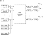
- FIG. 6 and FIG. 7 are diagrams of antenna ports 5, 7 and 8 (R5, R7, R8) corresponding to mobile station only reference signals.
- the mobile station reference signals shown in FIG. 6 and FIG. 7 they are characterized in that a mobile station is able to perform demodulation without description o special MIMO transmission scheme.
- a single radio frame can include M MBSFN subframes.
- a PDSCH region of the MBSFN subframe does not include a CRS.
- Rel-9 mobile station it is set not to receive PDSCH in the MBSFN subframe. Since the corresponding PDSCH region does not include the CRS, estimation for channel state information is not performed as well.
- a precoded demodulation reference signal RS is used and can be configured to transmit data on the PDSCH region of the MBSFN subframe.
- this subframe is recognized as the MBSFN subframe by the Rel-8 mobile station, it is recognized as a subframe capable of carrying PDSCH by the Rel-10 mobile station. This is named 'LTE-A only subframe' in the following description.
- Non-patent disclosure Texas Instruments: "Refinement on Downlink Reference Signal Design", 3GPP draft, R1-091291, 18 March 2009, XP050338898 , relates to refinements on downlink reference signal design.
- Non-patent disclosure Texas Instruments: " Common Reference Symbol Mapping/Signaling for 8 Transmit Antenna", 3GPP draft, R1-090591, 3 February 2009, XP050318479 , relates to common reference symbol mapping/signaling for 8 transmit antenna.
- a fallback mode is demodulated using CRS.
- CRS does not exist in PDSCH region, it is able to use the diversity scheme shown in Table 3.
- Rel-10 mobile station when scheduling is performed on the LTE-A only subframe, it is impossible to use the fallback mode. Therefore, the demand for a definition of a callback mode transmitting method in an LTE-A only subframe is rising.
- the present invention is directed to an apparatus for transmitting and receiving data in a wireless communication system method thereof that substantially obviate one or more of the problems due to limitations and disadvantages of the related art.
- An object of the present invention is to provide an apparatus for transmitting and receiving data in a wireless communication system method thereof, by which data for fallback mode transmission can be received in LTE-A only subframe.
- a method of receiving data which is received by a terminal in a wireless communication system, includes the steps of receiving a physical downlink control channel (hereinafter abbreviated PDCCH), receiving a physical downlink shared channel ((hereinafter abbreviated PDSCH), and demodulating the PDSCH by interpreting the PDCCH according to a type of a subframe including the PDCCH and the PDSCH.
- PDCCH physical downlink control channel
- PDSCH physical downlink shared channel
- the demodulating step includes the step of if the subframe is a mixed subframe, demodulating the PDSCH using a cell specific reference signal (hereinafter abbreviated CRS).
- CRS cell specific reference signal
- the demodulating step includes the step of if the subframe is an LTE-A only subframe, demodulating the PDSCH using a demodulation reference signal (hereinafter abbreviated DRS).
- DRS demodulation reference signal
- the method further includes the step of receiving information on a demodulation scheme of the LTE-A only subframe.
- the demodulating step includes the step of if the subframe is the LTE-A only subframe, demodulating the PDSCH according to the information on the demodulation scheme.
- an apparatus for receiving data which is received by a terminal in a wireless communication system, includes a receiving module configured to receive a physical downlink control channel (hereinafter abbreviated PDCCH) and a physical downlink shared channel ((hereinafter abbreviated PDSCH) and a processor configured to demodulate the PDSCH by interpreting the PDCCH according to a type of a subframe including the PDCCH and the PDSCH.
- PDCCH physical downlink control channel
- PDSCH physical downlink shared channel
- the processor demodulates the PDSCH using a cell specific reference signal (hereinafter abbreviated CRS).
- CRS cell specific reference signal
- the processor demodulates the PDSCH using a demodulation reference signal (hereinafter abbreviated DRS).
- DRS demodulation reference signal
- the receiving module receives information on a demodulation scheme of the LTE-A only subframe.
- the processor demodulates the PDSCH according to the information on the demodulation scheme.
- a control channel is interpreted differently according to a subframe type. Therefore, the present invention reduces scheduling constraint in a system including a plurality of subframe types and is able to raise efficiency of the control channel.
- a terminal is a common name of such a mobile or stationary user stage device as a user equipment (UE), a mobile station (MS) and the like and that a base station is a common name of such a random node of a network stage communicating with a terminal as a node B, eNode B, a base station and the like.
- UE user equipment
- MS mobile station
- a base station is a common name of such a random node of a network stage communicating with a terminal as a node B, eNode B, a base station and the like.
- the Rel-10 terminal uses a demodulation reference signal (hereinafter abbreviated DRS) for demodulation and also uses a channel state information reference signal (hereinafter abbreviated CSI-RS) for channel state information feedback.
- DRS demodulation reference signal
- CSI-RS channel state information reference signal
- FIG. 8 is a diagram of a transmission type of DRS.
- DRS is transmitted by having MIMO transmission scheme applied thereto like a data symbol
- a receiver is able to use the DRS for demodulation in direct.
- precoding is used as the MIMO transmission scheme
- the DRS is precoded and then transmitted.
- FIG. 9 is a diagram for a CSI-RS transmitting method.
- CSI-RS is transmitted via a corresponding physical antenna without having MIMO scheme applied thereto, a receiver is able to acquire channel information of the corresponding physical antenna using the CSI-RS.
- CRS of an Rel-8 system is transmitted according to a configuration shown in FIG. 9 , CRS is used for two purposes including channel state information estimation and demodulation.
- FIG. 10 is a diagram for a frame structure of a wireless communication system capable of supporting Rel-8 mobile station and Rel-10 mobile station both.
- a frame in order to enhance performance of 3GPP Rel-8 system and support Rel-8 terminal and Rel-10 terminal both, a frame includes CRS, DRS and CSI-RS. Yet, since the Rel-10 terminal does not use the CRS in demodulation received data, the CRS may be recognized as unnecessary overhead. Hence, in order to minimize an overhead, MBSFN subframe does not transmit the CRS in PDSCH region but transmits the DRS and the CSI-RS only. This subframe is called an LTE-A only subframe. And, the subframe transmitting the CRS in the PDSCH region is called a mixed subframe.
- Subframe types can include two kinds of types shown in Fig. 10 or a different kind of subframe type can be added thereto.
- the Rel-8 terminal can receive PDSCH in the mixed subframe shown in FIG. 10 only, recognizes other subframes as MBSFN subframes, and does not receive data in PDSCH region of another subframe. Yet, the Rel-10 terminal receives PDSCH in all subframes.
- FIG. 11 is a diagram of Rel-8 transmitter.
- an Rel-8 transmitter includes a scrambler 710, a modulation mapper 720, a layer mapper 730, a precoder 740, an OFDM mapper 750, and an OFDM signal generating unit 760.
- the scrambler 710 scrambles an inputted codeword.
- the modulation mapper 720 modulates an inputted signal.
- the layer mapper 730 maps the inputted signal to a layer.
- the precoder 740 multiplies the inputted signal by a precoding matrix.
- the OFDM mapper 750 maps the inputted signal to an OFDM symbol.
- the PFDM signal generating unit 760 generates an OFDM signal in a manner of performing inverse fast Fourier transform on the inputted signal and then adding a cyclic prefix thereto.
- FIG. 12 is a flowchart for a data receiving method according to a first embodiment of the present invention.
- a terminal receives PDCCH [S810] and then receives PDSCH [S820]. Subsequently, the terminal demodulates the PDSCH by interpreting the PDCCH according to a subframe type [S830]. In doing so, the terminal is able to demodulate the PDSCH in a manner of interpreting the same PDCCH differently according to the subframe type.
- a base station transmits the PDSCH using SISO transmission or diversity scheme according to the number of transmitting antennas in a mixed subframe or transmits the PDSCH by single layer transmission in an LTE-A only subframe.
- the terminal demodulates the PDSCH using CRS in the mixed subframe. Since the PDSCH of the LTE-A only subframe does not include the CRS, the terminal demodulates the PDSCH in the LTE-A only subframe using the DRS.
- the PDCCH is defined as a specific transmission mode and a transmission scheme for each PDCCH is determined according to the number of transmitting antennas of the corresponding system.
- a terminal receives the PDCCH, the same transmission scheme is always used irrespective of the properties of the subframe.
- Rel-10 system there exist a mixed subframe for scheduling Rel-8 terminal and Rel-10 terminal both and an LTE-A only subframe for scheduling the Rel-10 terminal only.
- the Rel-10 terminal can be scheduled in the above-mentioned subframes.
- a specific transmission scheme may not be available for a specific subframe type. Therefore, it is preferable that a different transmission scheme is used according to a subframe type in a specific transmission mode.
- a transmission mode and scheme used by 3GPP TS 36.213 V9.0.1 and the connectivity between PDCCH and transmission mode are shown in Table 4.
- a configuration of PDCCH can use DCI format 1A or CDI format 1.
- the DCI format 1A is configured to use a transmit diversity scheme as a fallback transmission scheme or the DCI format 1 is configured to use a large delay CDD transmission scheme or a transmit diversity scheme.
- each transmission mode and DCI format has a corresponding transmission scheme determined according to a DCI format irrespective of a subframe type.
- a search space indicates a region of a PDCCH for detecting the corresponding DCI format.
- a terminal has to set demodulation to differ according to a subframe type while receiving the same DCI format.
- a subframe type 1 e.g., a mixed subframe
- a subframe type 2 e.g., an LTE-A only subframe
- a specific terminal type e.g., Rel-10 terminal
- a specific terminal type e.g., Rel-8 terminal
- Single-antenna port. port 0 is used (see subclause 7.1.1), otherwise Transmit diversity (see subclause 7.1.2) DCI format 1 UE specific by C- RNTI Single-antenna port: port 5 (see subclause 7.1.1) Mode 8 DCI format 1A Common andUE specific by C- RNTI If the number of PBCH antenna ports is one.
- Single-antenna port. port 0 is used (see subclause 7.1.1), otherwise Transmit diversity (see subclause 7.1.2) DCI format 2B UE specific by C- RNTI Dual layer transmission: port 7 and 8 (see subclause 7.1.5A) or single-antenna port; port 7 or 8 (see subclause 7.1.1)
- a new transmission mode for Rel-10 terminal can be configured in addition. For instance, if Mode 9 is added, the corresponding usage is shown in Table 5.
- [Table] Transmission mode DCI format Search Space Transmission scheme of PDSCH corresponding to PDCCH Mode 1 DCI format 1A Common andUE specific by C- RNTI Single-antenna port. port 0 (see subclause 7.1.1) DCI format 1 UE specific by C- RNTI Single-antenna port.
- Single-antenna port.port 0 is used (see subclause 7.1.1), otherwise Transmit diversity (see subclause 7.1.2) DCI format 2B UE specific by C- RNTI Dual layer transmission: port 7 and 8 (see subclause 7.1.5A) or single-antenna port: port 7 or 8 (see subclause 7.1.1) Mode 9 DCI format 1A Common andUE specific by C- RNTI Subframe type-1:If the number of PBCH antenna ports is one. Single-antenna port. port 0 is used (see subclause 7.1.1), otherwise Transmit diversity (see subclause 7.1.2) Subframe type-2:Single-antenna port. port 7 is used DCI format 2C UE specific by C- RNTI Multi layer transmission: port 7 to port 14 or single-antenna port: port 7 or 8 (see subclause 7.1.1)
- DCI format 1A used as fallback uses a transmission scheme different according to a subframe type.
- it is able to separately define whether to use port 0 or port 7 according to a subframe type.
- the above mentioned subframe type can be notified to a specific terminal type only. And, the corresponding information can be announced via an RRC signal, a radio frame head or the like or can be broadcasted via a broadcasting channel.
- At least tow subframe types can be defined and the number of species of configurable subframe types may vary according to a terminal type.
- FIG. 13 is a flowchart for a data receiving method according to a second embodiment of the present invention.
- a terminal receives information on a demodulation method of an LTE-A only subframe [S910].
- the terminal receives information indicating whether to demodulate PDSCH of an LTE-A only subframe using CRS from a base station or PDSCH of an LTE-A only subframe using DRS.
- the terminal is able to receive information on a demodulation method via PDCCH or RRC signaling.
- the base station transmit PDSCH using MIMO transmission scheme irrespective of a subframe type or is able to transmit PDSCH by a different scheme according to a subframe type.
- the base station transmits PDSCH in a mixed subframe using an MIMO transmission scheme or transmits PDSCH in an LTE-A only subframe using a single layer transmission scheme.
- the base station transmits the PSCH of the LTE-A only subframe using the MIMO transmission scheme or the single layer transmission scheme.
- the base station instructs the terminal to demodulate the PDSCH using the CRS.
- the base station instructs the terminal to demodulate the PDSCH using the DRS.
- the terminal receives the PDSCH [S920] and then receives the PDSCH [S930].
- the terminal demodulates the PDSCH by interpreting the PDCCH according to the subframe type [S940]. In doing so, the terminal is able to demodulate the PDSCH in a manner of interpreting the same PDCCH differently according to the subframe type.
- the base station transmits the PDSCH using the SISO transmission or diversity scheme according to the number of transmitting antennas in the mixed frame or transmits the PDSCH in the LTE-A only subframe using the diversity scheme or the single layer transmission scheme.
- the terminal demodulates the PDSCH using the CRS in the mixed frame or demodulates the PDSCH in the LTE-A only subframe according to the information on the demodulation scheme received in the step S910.
- the terminal demodulates the PDSCH of the LTE-A only subframe using the CRS of the next subframe.
- the terminal receives the instruction to demodulate the PDSCH of the LTE-A only subframe using the DRS
- the terminal demodulates the PDSCH of the LTE-A only subframe using the DRS.
- the same DCI format can indicate a content different according to the subframe type. For instance, it is able to configure an MIMO transmission mode to differ according to the subframe type despite the same DCI format.
- the same DCI format indicates that data is transmitted in a single user MIMO mode or a multi-user MIMO mode in the mixed subframe or indicates that data is transmitted in CoMP (cooperative multi-point) in the LTE-A only subframe.
- the PDCCH constructed with the same bit number is used, it can be used in a manner off being interpreted differently according to the subframe type.
- the DCI format 1A is used in the mixed subframe and a DCI format IE having the same information bit number is configured and used in the LTE-A only subframe.
- the LTE-A terminal is able to interpret a DCI format differently according to a subframe type despite receiving the DCI format of the same size.
- FIG. 14 is a diagram for configurations of a mobile station and a base station for implementing embodiments of the present invention according to another embodiment of the present invention.
- a mobile station/base station includes an antenna 1000/1010 configured to transmit and receive information, data, signals, messages and/ or the like, a transmitting (Tx) module 1040/1050 transmitting a message by controlling the antenna, a receiving (Rx) module 1060/1070 receiving a message by controlling the antenna, a memory 1080/1090 configured to store informations related to communication with the base station, and a processor 1020/1030 configured to control the receiving module and the memory.
- the base station can include a femto base station or a macro base station.
- the antenna 1000/1010 plays a role in transmitting a signal generated by the transmitting module 1040/1050 externally and also plays a role in receiving an external radio signal and then forwarding the received radio signal to the receiving module 1060/10100.
- at least two antennas can be provided.
- the processor 1020/1030 normally controls overall operations of the mobile station or the base station.
- the processor 1020/1030 is able to perform a control function, a MAC (medium access control) frame variable control function according to service characteristics and radio wave environment, a handover function, an authentication function, an encryption function and the like to implement the above mentioned embodiments of the present invention.
- the processor 1020/1030 is able to further include an encryption module configured to control encryption of various messages and a timer module configured to control transmission and reception of various messages.
- the transmitting module 1040/1050 performs prescribed coding and modulation on a signal and/or data, which is scheduled by the processor and will be externally transmitted, and then delivers the coded and modulated signal and/or data to the antenna 1000/1010.
- the receiving module 1060/1070 reconstructs a radio signal externally received via the antenna 1000/1010 into original data by performing decoding and demodulation on the received radio signal and is then able to deliver the reconstructed data to the processor 1020/1030.
- Programs for processing and control of the processor can be stored in the memory 1080/1090.
- the memory 1080/1090 can perform a function of temporary storage of inputted/outputted data (in case of a mobile station, an uplink (UL) grant allocated by a base station, system information, a station identifier (STID), a flow identifier (FID), an action time, region allocation information, frame offset information, etc.).
- UL uplink
- TDD station identifier
- FID flow identifier
- action time region allocation information
- frame offset information etc.
- the memory 1080/1090 can include at least one of storage media including a flash memory type memory, a hard disk type memory, a multimedia card micro type memory), a card type memory (e.g., SD memory, XD memory, etc.), a Random Access Memory (RAM), an SRAM (Static Random Access Memory), a Read-Only Memory (ROM), an EEPROM (Electrically Erasable Programmable Read-Only Memory, a PROM (Programmable Read-Only Memory), a magnetic memory, a magnetic disk, an optical disk and the like.
- storage media including a flash memory type memory, a hard disk type memory, a multimedia card micro type memory), a card type memory (e.g., SD memory, XD memory, etc.), a Random Access Memory (RAM), an SRAM (Static Random Access Memory), a Read-Only Memory (ROM), an EEPROM (Electrically Erasable Programmable Read-Only Memory, a PROM (Programmable Read-Only Memory), a magnetic
Landscapes
- Engineering & Computer Science (AREA)
- Signal Processing (AREA)
- Computer Networks & Wireless Communication (AREA)
- Mobile Radio Communication Systems (AREA)
- Radio Transmission System (AREA)
Claims (12)
- Verfahren zum Empfangen, durch ein Endgerät, von Daten in einem drahtlosen Kommunikationssystem, umfassend:Empfangen eines Physical Downlink Control Channel, PDCCH, mit Downlink-Steuerinformationsformat 1A in einem Unterrahmen; undEmpfangen eines Physical Downlink Shared Channel, PDSCH, der dem PDCCH im Unterrahmen entspricht,wobeider PDSCH auf der Grundlage eines zellspezifischen Referenzsignals demoduliert wird, wenn der Unterrahmen kein Multimedia Broadcast Multicast Service Single Frequency Network-, MBSFN-, Unterrahmen ist, undder PDSCH auf der Grundlage eines Demodulationsreferenzsignals demoduliert wird, wenn der Unterrahmen ein MBSFN-Unterrahmen ist.
- Verfahren nach Anspruch 1, wobei, wenn der Unterrahmen kein MBSFN-Unterrahmen ist, das Endgerät den PDSCH demoduliert, unter der Annahme, dass der PDSCH unter Verwendung eines Einzelantennen-Sendeschemas oder eines Sendediversitätsschemas auf der Grundlage des zellspezifischen Referenzsignals gesendet wird.
- Verfahren nach Anspruch 1 oder 2, wobei, wenn der Unterrahmen ein MBSFN-Unterrahmen ist, das Endgerät den PDSCH demoduliert, unter der Annahme, dass der PDSCH unter Verwendung eines Einzelschicht-Sendeschemas auf der Grundlage des Demodulationsreferenzsignals gesendet wird.
- Endgerät zum Empfangen von Daten für ein drahtloses Kommunikationssystem, umfassend:ein Empfangsmodul (1070), das zum Empfangen eines Physical Downlink Control Channel, PDCCH, mit Downlink-Steuerinformationsformat 1A in einem Unterrahmen sowie zum Empfangen eines Physical Downlink Shared Channel, PDSCH, der dem PDCCH im Unterrahmen entspricht, konfiguriert ist; undeinen Prozessor (1030), der zur Steuerung des Empfangsmoduls (1070) konfiguriert ist,wobeider PDSCH auf der Grundlage eines zellspezifischen Referenzsignals demoduliert wird, wenn der Unterrahmen kein Multimedia Broadcast Multicast Service Single Frequency Network-, MBSFN-, Unterrahmen ist, undder PDSCH auf der Grundlage eines Demodulationsreferenzsignals demoduliert wird, wenn der Unterrahmen ein MBSFN-Unterrahmen ist.
- Endgerät nach Anspruch 4, wobei, wenn der Unterrahmen kein MBSFN-Unterrahmen ist, der Prozessor (1030) den PDSCH demoduliert, unter der Annahme, dass der PDSCH unter Verwendung eines Einzelantennen-Sendeschemas oder eines Sendediversitätschemas auf der Grundlage des zellspezifischen Referenzsignals gesendet wird.
- Endgerät nach Anspruch 4 oder 5, wobei, wenn der Unterrahmen ein MBSFN-Unterrahmen ist, der Prozessor (1030) den PDSCH demoduliert, unter der Annahme, dass der PDSCH unter Verwendung eines Einzelschicht-Sendeschemas auf der Grundlage des Demodulationsreferenzsignals gesendet wird.
- Verfahren zum Senden, durch eine Basisstation, von Daten in einem drahtlosen Kommunikationssystem, umfassend:Senden eines Physical Downlink Control Channel, PDCCH, mit Downlink-Steuerinformationsformat 1A an ein Endgerät in einem Unterrahmen; undSenden eines Physical Downlink Shared Channel, PDSCH, der dem PDCCH entspricht, an das Endgerät im Unterrahmen,wobeider PDSCH auf der Grundlage eines zellspezifischen Referenzsignals gesendet wird, wenn der Unterrahmen kein Multimedia Broadcast Multicast Service Single Frequency Network-, MBSFN-, Unterrahmen ist, undder PDSCH auf der Grundlage eines Demodulationsreferenzsignals gesendet wird, wenn der Unterrahmen ein MBSFN-Unterrahmen ist.
- Verfahren nach Anspruch 7, wobei, wenn der Unterrahmen kein MBSFN-Unterrahmen ist, der PDSCH unter Verwendung eines Einzelantennen-Sendeschemas oder Sendediversitätsschemas auf der Grundlage des zellspezifischen Referenzsignals gesendet wird.
- Verfahren nach Anspruch 7 oder 8, wobei, wenn der Unterrahmen ein MBSFN-Unterrahmen ist, der PDSCH unter Verwendung eines Einzelschicht-Sendeschemas auf der Grundlage des Demodulationsreferenzsignals gesendet wird.
- Basisstation zum Senden von Daten für ein drahtloses Kommunikationssystem, umfassend:ein Sendemodul (1040); undeinen Prozessor (1020), der zur Steuerung des Sendemoduls (1040) konfiguriert ist,wobei das Sendemodul (1040) einen Physical Downlink Control Channel, PDCCH, mit Downlink-Steuerinformationsformat 1A an ein Endgerät in einem Unterrahmen sendet und einen Physical Downlink Shared Channel, PDSCH, der dem PDCCH entspricht, an das Endgerät im Unterrahmen sendet,wobeider PDSCH auf der Grundlage eines zellspezifischen Referenzsignals gesendet wird, wenn der Unterrahmen kein Multimedia Broadcast Multicast Service Single Frequency Network-, MBSFN-, Unterrahmen ist, undder PDSCH auf der Grundlage eines Demodulationsreferenzsignals gesendet wird, wenn der Unterrahmen ein MBSFN-Unterrahmen ist.
- Basisstation nach Anspruch 10, wobei, wenn der Unterrahmen kein MBSFN-Unterrahmen ist, das Sendemodul den PDSCH unter Verwendung eines Einzelantennen-Sendeschemas oder eines Sendediversitätsschemas auf der Grundlage des zellspezifischen Referenzsignals sendet.
- Basisstation nach Anspruch 10 oder 11, wobei, wenn der Unterrahmen ein MBSFN-Unterrahmen ist, das Sendemodul (1040) den PDSCH unter Verwendung eines Einzelschicht-Sendeschemas auf der Grundlage des Demodulationsreferenzsignals sendet.
Applications Claiming Priority (3)
| Application Number | Priority Date | Filing Date | Title |
|---|---|---|---|
| US21929109P | 2009-06-22 | 2009-06-22 | |
| KR1020100049835A KR101349840B1 (ko) | 2009-06-22 | 2010-05-27 | 무선 통신 시스템에서 데이터 송수신 방법 및 장치 |
| PCT/KR2010/003854 WO2010151000A2 (en) | 2009-06-22 | 2010-06-15 | Apparatus for transmitting and receiving data in a wireless communication system and method thereof |
Publications (3)
| Publication Number | Publication Date |
|---|---|
| EP2446569A2 EP2446569A2 (de) | 2012-05-02 |
| EP2446569A4 EP2446569A4 (de) | 2017-02-15 |
| EP2446569B1 true EP2446569B1 (de) | 2018-11-07 |
Family
ID=43511123
Family Applications (1)
| Application Number | Title | Priority Date | Filing Date |
|---|---|---|---|
| EP10792282.5A Active EP2446569B1 (de) | 2009-06-22 | 2010-06-15 | Vorrichtung zum senden und empfangen in einem drahtlosen kommunikationssystem und verfahren dafür |
Country Status (6)
| Country | Link |
|---|---|
| US (3) | US8711777B2 (de) |
| EP (1) | EP2446569B1 (de) |
| KR (1) | KR101349840B1 (de) |
| CN (2) | CN102804657B (de) |
| ES (1) | ES2701005T3 (de) |
| WO (1) | WO2010151000A2 (de) |
Families Citing this family (36)
| Publication number | Priority date | Publication date | Assignee | Title |
|---|---|---|---|---|
| KR101349840B1 (ko) * | 2009-06-22 | 2014-01-09 | 엘지전자 주식회사 | 무선 통신 시스템에서 데이터 송수신 방법 및 장치 |
| WO2011013986A2 (en) * | 2009-07-30 | 2011-02-03 | Lg Electronics Inc. | Apparatus and method for transmitting channel state information in a mobile communication system |
| US9374148B2 (en) * | 2009-11-17 | 2016-06-21 | Qualcomm Incorporated | Subframe dependent transmission mode in LTE-advanced |
| US8824384B2 (en) * | 2009-12-14 | 2014-09-02 | Samsung Electronics Co., Ltd. | Systems and methods for transmitting channel quality information in wireless communication systems |
| US9986388B2 (en) * | 2010-10-06 | 2018-05-29 | Unwired Planet International Limited | Method and apparatus for transmitting and receiving data |
| JP5985491B2 (ja) | 2010-11-08 | 2016-09-06 | サムスン エレクトロニクス カンパニー リミテッド | 無線通信システムで互いに異なる形態のサブフレームを受信する方法及び装置 |
| US8842622B2 (en) | 2011-01-07 | 2014-09-23 | Interdigital Patent Holdings, Inc. | Method, system and apparatus for downlink shared channel reception in cooperative multipoint transmissions |
| KR101540869B1 (ko) | 2011-02-10 | 2015-07-30 | 엘지전자 주식회사 | 스케줄링 정보 모니터링 방법 및 장치 |
| EP3113567B1 (de) | 2011-02-11 | 2018-04-11 | Interdigital Patent Holdings, Inc. | Systeme und verfahren für einen verbesserten steuerkanal |
| CN105610483B (zh) | 2011-03-29 | 2019-03-12 | Lg电子株式会社 | 在无线通信系统中决定资源特定传输模式的方法及其设备 |
| KR101948801B1 (ko) * | 2011-04-11 | 2019-02-18 | 삼성전자주식회사 | Mbms 지원 사용자 장치의 데이터 수신 방법 및 장치 |
| KR20130007928A (ko) * | 2011-07-11 | 2013-01-21 | 주식회사 팬택 | 전송단의 하향링크 제어 채널 전송 방법, 그 전송단, 단말의 하향링크 제어 채널 수신 방법, 그 단말 |
| US20130083681A1 (en) * | 2011-09-30 | 2013-04-04 | Research In Motion Limited | Methods of Channel State Information Feedback and Transmission in Coordinated Multi-Point Wireless Communications System |
| WO2013028005A2 (ko) * | 2011-08-22 | 2013-02-28 | 엘지전자 주식회사 | 장치 간 통신을 지원하는 무선 접속 시스템에서 장치 간 데이터 전송 방식 및 이를 위한 장치 |
| WO2013048108A2 (ko) * | 2011-09-28 | 2013-04-04 | 엘지전자 주식회사 | 무선통신시스템에서 제어정보 획득 방법 및 장치 |
| KR101754281B1 (ko) * | 2011-11-04 | 2017-07-06 | 인텔 코포레이션 | 기지국 협력 통신 시스템의 전송 포인트 표시 |
| WO2013071486A1 (en) * | 2011-11-15 | 2013-05-23 | Nokia Siemens Networks Oy | A method and apparatus |
| KR101967298B1 (ko) * | 2011-12-16 | 2019-08-13 | 엘지전자 주식회사 | 다중 셀 시스템에서 물리 채널에 대한 자원 매핑 방법 및 장치 |
| CN104081709B (zh) | 2012-01-27 | 2017-09-08 | 交互数字专利控股公司 | 用于在基于多载波和/或准校准网络中提供ePDCCH的装置和/或方法 |
| KR102000093B1 (ko) * | 2012-01-27 | 2019-07-15 | 삼성전자주식회사 | 무선 통신 시스템에서 데이터를 송수신하는 방법 및 장치 |
| KR101594378B1 (ko) * | 2012-03-09 | 2016-02-16 | 엘지전자 주식회사 | 신호 송수신 방법 및 이를 위한 장치 |
| PL2826192T3 (pl) * | 2012-03-16 | 2018-01-31 | Nokia Solutions & Networks Oy | Ślepe dekodowanie |
| US20130250879A1 (en) * | 2012-03-22 | 2013-09-26 | Samsung Electronics Co., Ltd | Method and apparatus for transmission mode design for extension carrier of lte advanced |
| CN104205981B (zh) * | 2012-06-25 | 2018-01-09 | Lg 电子株式会社 | 在无线通信系统中分配用于下行链路控制信道的资源的方法和装置及其设备 |
| EP2874456B1 (de) * | 2012-08-03 | 2019-10-09 | Huawei Technologies Co., Ltd. | Informationsübertragungsverfahren, endgerät und basisstation |
| GB201214137D0 (en) * | 2012-08-07 | 2012-09-19 | Gen Dynamics Broadband Inc | Communication unit, integrated circuit and method for supporting a virtual carrier |
| US9307521B2 (en) * | 2012-11-01 | 2016-04-05 | Samsung Electronics Co., Ltd. | Transmission scheme and quasi co-location assumption of antenna ports for PDSCH of transmission mode 10 for LTE advanced |
| US11139862B2 (en) * | 2012-11-02 | 2021-10-05 | Samsung Electronics Co., Ltd. | Configuration of rate matching and interference measurement resources for coordinated multi-point transmission |
| US20160028521A1 (en) * | 2013-03-13 | 2016-01-28 | Sharp Kabushiki Kaisha | Base station, terminal, communication system, communication method, and integrated circuit |
| CN105247801B (zh) * | 2013-05-16 | 2019-03-29 | Lg电子株式会社 | 发送用于提高覆盖范围的信号的方法及其设备 |
| KR102184909B1 (ko) * | 2013-07-15 | 2020-12-01 | 삼성전자주식회사 | 무선 통신 시스템에서 간섭 신호 제거 방법 및 장치 |
| WO2016119198A1 (en) | 2015-01-30 | 2016-08-04 | Qualcomm Incorporated | Support of transmission mode and impact on pdcch blind decodes of ptm (point-to-multipoint) transmission |
| CN106559880B (zh) * | 2015-09-25 | 2021-11-02 | 中兴通讯股份有限公司 | 发现信号和物理下行共享信道复用发送、接收方法和设备 |
| US10958404B2 (en) * | 2015-11-06 | 2021-03-23 | Qualcomm Incorporated | Discovery reference signal configuration and scrambling in licensed-assisted access |
| CN107453852B (zh) * | 2016-05-31 | 2020-05-15 | 电信科学技术研究院 | 一种子帧类型通知、确定方法及装置 |
| EP3694130B1 (de) * | 2017-11-13 | 2022-01-05 | LG Electronics Inc. | Verfahren zum senden und empfangen von daten in einem drahtloskommunikationssystem und vorrichtung dafür |
Family Cites Families (9)
| Publication number | Priority date | Publication date | Assignee | Title |
|---|---|---|---|---|
| USRE43949E1 (en) | 2006-01-05 | 2013-01-29 | Lg Electronics Inc. | Allocating radio resources in mobile communications system |
| WO2008156034A1 (ja) * | 2007-06-18 | 2008-12-24 | Sharp Kabushiki Kaisha | 移動局、移動通信システム及び通信方法 |
| EP2661133B1 (de) * | 2007-08-08 | 2016-06-15 | Huawei Technologies Co., Ltd. | Zeitliche Anpassung in einem Funkkommunikationssystem |
| US8767634B2 (en) * | 2007-08-14 | 2014-07-01 | Lg Electronics Inc. | Method for acquiring resource region information for PHICH and method of receiving PDCCH |
| KR101438238B1 (ko) * | 2007-10-29 | 2014-09-12 | 엘지전자 주식회사 | 무선통신 시스템에서 랜덤 액세스 과정 수행 방법 |
| US8600413B2 (en) * | 2007-10-30 | 2013-12-03 | Qualcomm Incorporated | Control arrangement and method for communicating paging messages in a wireless communication system |
| KR101537607B1 (ko) * | 2008-02-05 | 2015-07-29 | 엘지전자 주식회사 | 조정필드를 이용한 효율적인 무선채널 전송방법 |
| KR101349840B1 (ko) * | 2009-06-22 | 2014-01-09 | 엘지전자 주식회사 | 무선 통신 시스템에서 데이터 송수신 방법 및 장치 |
| US8305987B2 (en) * | 2010-02-12 | 2012-11-06 | Research In Motion Limited | Reference signal for a coordinated multi-point network implementation |
-
2010
- 2010-05-27 KR KR1020100049835A patent/KR101349840B1/ko active Active
- 2010-06-15 CN CN201080027632.7A patent/CN102804657B/zh active Active
- 2010-06-15 WO PCT/KR2010/003854 patent/WO2010151000A2/en not_active Ceased
- 2010-06-15 ES ES10792282T patent/ES2701005T3/es active Active
- 2010-06-15 EP EP10792282.5A patent/EP2446569B1/de active Active
- 2010-06-15 CN CN201510276046.0A patent/CN104954107B/zh active Active
- 2010-06-15 US US13/380,492 patent/US8711777B2/en active Active
-
2014
- 2014-03-10 US US14/203,027 patent/US9185683B2/en active Active
-
2015
- 2015-10-07 US US14/877,813 patent/US9510323B2/en active Active
Non-Patent Citations (1)
| Title |
|---|
| None * |
Also Published As
| Publication number | Publication date |
|---|---|
| US20160037485A1 (en) | 2016-02-04 |
| WO2010151000A9 (en) | 2011-05-05 |
| US20120099536A1 (en) | 2012-04-26 |
| KR101349840B1 (ko) | 2014-01-09 |
| WO2010151000A3 (en) | 2011-03-03 |
| WO2010151000A2 (en) | 2010-12-29 |
| US9185683B2 (en) | 2015-11-10 |
| CN102804657B (zh) | 2015-06-24 |
| US20140192700A1 (en) | 2014-07-10 |
| CN102804657A (zh) | 2012-11-28 |
| ES2701005T3 (es) | 2019-02-20 |
| CN104954107B (zh) | 2018-07-17 |
| US8711777B2 (en) | 2014-04-29 |
| EP2446569A4 (de) | 2017-02-15 |
| EP2446569A2 (de) | 2012-05-02 |
| US9510323B2 (en) | 2016-11-29 |
| KR20100137357A (ko) | 2010-12-30 |
| CN104954107A (zh) | 2015-09-30 |
Similar Documents
| Publication | Publication Date | Title |
|---|---|---|
| EP2446569B1 (de) | Vorrichtung zum senden und empfangen in einem drahtlosen kommunikationssystem und verfahren dafür | |
| JP7469843B2 (ja) | 無線通信システムにおいて制御情報をマッピングするための方法及び装置 | |
| CN102624489B (zh) | 一种增强的控制信道传输的方法、装置及系统 | |
| US8811321B2 (en) | Method for transceiving a downlink reference signal, and base station and user equipment using same | |
| US9848415B2 (en) | DM RD based LTE downlink physical layer | |
| KR101331868B1 (ko) | 릴레이 링크 제어 채널 설계 | |
| EP2642709B1 (de) | Verfahren und vorrichtung zum senden und empfangen eines abwärtssteuerkanals in einem drahtlosen kommunikationssystem | |
| EP2777353B1 (de) | Netzwerkknoten, benutzervorrichtung und verfahren darin zum senden und empfangen von steuerinformationen | |
| EP3365984B1 (de) | Dynamische vorcodierung von gemeinsamen referenzsignalen | |
| US8520601B2 (en) | Method and apparatus for acquiring antenna information in a wireless communication system | |
| KR20100119508A (ko) | 무선 통신 시스템에서 데이터 송수신 방법 및 장치 | |
| KR20110088458A (ko) | 릴레이 백홀 링크에서 신호를 전송하는 방법 및 이를 위한 장치 | |
| JP2015534402A (ja) | 制御情報を送受信する方法およびそのための装置 | |
| WO2015065151A1 (ko) | Mtc를 위한 신호 처리 방법 및 이를 위한 장치 | |
| CA3113638C (en) | Channel state information reference signal | |
| KR101706959B1 (ko) | 무선 통신 시스템에서 데이터 송수신 방법 및 장치 |
Legal Events
| Date | Code | Title | Description |
|---|---|---|---|
| PUAI | Public reference made under article 153(3) epc to a published international application that has entered the european phase |
Free format text: ORIGINAL CODE: 0009012 |
|
| 17P | Request for examination filed |
Effective date: 20111223 |
|
| AK | Designated contracting states |
Kind code of ref document: A2 Designated state(s): AL AT BE BG CH CY CZ DE DK EE ES FI FR GB GR HR HU IE IS IT LI LT LU LV MC MK MT NL NO PL PT RO SE SI SK SM TR |
|
| DAX | Request for extension of the european patent (deleted) | ||
| A4 | Supplementary search report drawn up and despatched |
Effective date: 20170116 |
|
| RIC1 | Information provided on ipc code assigned before grant |
Ipc: H04L 5/00 20060101AFI20170110BHEP Ipc: H04J 11/00 20060101ALI20170110BHEP Ipc: H04W 28/06 20090101ALN20170110BHEP |
|
| GRAP | Despatch of communication of intention to grant a patent |
Free format text: ORIGINAL CODE: EPIDOSNIGR1 |
|
| STAA | Information on the status of an ep patent application or granted ep patent |
Free format text: STATUS: GRANT OF PATENT IS INTENDED |
|
| RIC1 | Information provided on ipc code assigned before grant |
Ipc: H04W 28/06 20090101ALN20171213BHEP Ipc: H04J 11/00 20060101ALI20171213BHEP Ipc: H04L 5/00 20060101AFI20171213BHEP |
|
| INTG | Intention to grant announced |
Effective date: 20180103 |
|
| GRAJ | Information related to disapproval of communication of intention to grant by the applicant or resumption of examination proceedings by the epo deleted |
Free format text: ORIGINAL CODE: EPIDOSDIGR1 |
|
| STAA | Information on the status of an ep patent application or granted ep patent |
Free format text: STATUS: REQUEST FOR EXAMINATION WAS MADE |
|
| REG | Reference to a national code |
Ref country code: DE Ref legal event code: R079 Ref document number: 602010054957 Country of ref document: DE Free format text: PREVIOUS MAIN CLASS: H04J0011000000 Ipc: H04L0005000000 |
|
| GRAP | Despatch of communication of intention to grant a patent |
Free format text: ORIGINAL CODE: EPIDOSNIGR1 |
|
| STAA | Information on the status of an ep patent application or granted ep patent |
Free format text: STATUS: GRANT OF PATENT IS INTENDED |
|
| INTC | Intention to grant announced (deleted) | ||
| RIC1 | Information provided on ipc code assigned before grant |
Ipc: H04J 11/00 20060101ALI20180508BHEP Ipc: H04W 28/06 20090101ALN20180508BHEP Ipc: H04L 5/00 20060101AFI20180508BHEP |
|
| INTG | Intention to grant announced |
Effective date: 20180530 |
|
| GRAS | Grant fee paid |
Free format text: ORIGINAL CODE: EPIDOSNIGR3 |
|
| GRAA | (expected) grant |
Free format text: ORIGINAL CODE: 0009210 |
|
| STAA | Information on the status of an ep patent application or granted ep patent |
Free format text: STATUS: THE PATENT HAS BEEN GRANTED |
|
| AK | Designated contracting states |
Kind code of ref document: B1 Designated state(s): AL AT BE BG CH CY CZ DE DK EE ES FI FR GB GR HR HU IE IS IT LI LT LU LV MC MK MT NL NO PL PT RO SE SI SK SM TR |
|
| REG | Reference to a national code |
Ref country code: GB Ref legal event code: FG4D |
|
| REG | Reference to a national code |
Ref country code: CH Ref legal event code: EP Ref country code: AT Ref legal event code: REF Ref document number: 1063359 Country of ref document: AT Kind code of ref document: T Effective date: 20181115 |
|
| REG | Reference to a national code |
Ref country code: IE Ref legal event code: FG4D |
|
| REG | Reference to a national code |
Ref country code: DE Ref legal event code: R096 Ref document number: 602010054957 Country of ref document: DE |
|
| REG | Reference to a national code |
Ref country code: NL Ref legal event code: FP |
|
| REG | Reference to a national code |
Ref country code: ES Ref legal event code: FG2A Ref document number: 2701005 Country of ref document: ES Kind code of ref document: T3 Effective date: 20190220 |
|
| REG | Reference to a national code |
Ref country code: LT Ref legal event code: MG4D |
|
| REG | Reference to a national code |
Ref country code: AT Ref legal event code: MK05 Ref document number: 1063359 Country of ref document: AT Kind code of ref document: T Effective date: 20181107 |
|
| PG25 | Lapsed in a contracting state [announced via postgrant information from national office to epo] |
Ref country code: FI Free format text: LAPSE BECAUSE OF FAILURE TO SUBMIT A TRANSLATION OF THE DESCRIPTION OR TO PAY THE FEE WITHIN THE PRESCRIBED TIME-LIMIT Effective date: 20181107 Ref country code: IS Free format text: LAPSE BECAUSE OF FAILURE TO SUBMIT A TRANSLATION OF THE DESCRIPTION OR TO PAY THE FEE WITHIN THE PRESCRIBED TIME-LIMIT Effective date: 20190307 Ref country code: NO Free format text: LAPSE BECAUSE OF FAILURE TO SUBMIT A TRANSLATION OF THE DESCRIPTION OR TO PAY THE FEE WITHIN THE PRESCRIBED TIME-LIMIT Effective date: 20190207 Ref country code: AT Free format text: LAPSE BECAUSE OF FAILURE TO SUBMIT A TRANSLATION OF THE DESCRIPTION OR TO PAY THE FEE WITHIN THE PRESCRIBED TIME-LIMIT Effective date: 20181107 Ref country code: LV Free format text: LAPSE BECAUSE OF FAILURE TO SUBMIT A TRANSLATION OF THE DESCRIPTION OR TO PAY THE FEE WITHIN THE PRESCRIBED TIME-LIMIT Effective date: 20181107 Ref country code: LT Free format text: LAPSE BECAUSE OF FAILURE TO SUBMIT A TRANSLATION OF THE DESCRIPTION OR TO PAY THE FEE WITHIN THE PRESCRIBED TIME-LIMIT Effective date: 20181107 Ref country code: BG Free format text: LAPSE BECAUSE OF FAILURE TO SUBMIT A TRANSLATION OF THE DESCRIPTION OR TO PAY THE FEE WITHIN THE PRESCRIBED TIME-LIMIT Effective date: 20190207 Ref country code: HR Free format text: LAPSE BECAUSE OF FAILURE TO SUBMIT A TRANSLATION OF THE DESCRIPTION OR TO PAY THE FEE WITHIN THE PRESCRIBED TIME-LIMIT Effective date: 20181107 |
|
| PG25 | Lapsed in a contracting state [announced via postgrant information from national office to epo] |
Ref country code: AL Free format text: LAPSE BECAUSE OF FAILURE TO SUBMIT A TRANSLATION OF THE DESCRIPTION OR TO PAY THE FEE WITHIN THE PRESCRIBED TIME-LIMIT Effective date: 20181107 Ref country code: PT Free format text: LAPSE BECAUSE OF FAILURE TO SUBMIT A TRANSLATION OF THE DESCRIPTION OR TO PAY THE FEE WITHIN THE PRESCRIBED TIME-LIMIT Effective date: 20190307 Ref country code: GR Free format text: LAPSE BECAUSE OF FAILURE TO SUBMIT A TRANSLATION OF THE DESCRIPTION OR TO PAY THE FEE WITHIN THE PRESCRIBED TIME-LIMIT Effective date: 20190208 Ref country code: SE Free format text: LAPSE BECAUSE OF FAILURE TO SUBMIT A TRANSLATION OF THE DESCRIPTION OR TO PAY THE FEE WITHIN THE PRESCRIBED TIME-LIMIT Effective date: 20181107 |
|
| PG25 | Lapsed in a contracting state [announced via postgrant information from national office to epo] |
Ref country code: CZ Free format text: LAPSE BECAUSE OF FAILURE TO SUBMIT A TRANSLATION OF THE DESCRIPTION OR TO PAY THE FEE WITHIN THE PRESCRIBED TIME-LIMIT Effective date: 20181107 Ref country code: PL Free format text: LAPSE BECAUSE OF FAILURE TO SUBMIT A TRANSLATION OF THE DESCRIPTION OR TO PAY THE FEE WITHIN THE PRESCRIBED TIME-LIMIT Effective date: 20181107 Ref country code: DK Free format text: LAPSE BECAUSE OF FAILURE TO SUBMIT A TRANSLATION OF THE DESCRIPTION OR TO PAY THE FEE WITHIN THE PRESCRIBED TIME-LIMIT Effective date: 20181107 |
|
| REG | Reference to a national code |
Ref country code: DE Ref legal event code: R097 Ref document number: 602010054957 Country of ref document: DE |
|
| PG25 | Lapsed in a contracting state [announced via postgrant information from national office to epo] |
Ref country code: SM Free format text: LAPSE BECAUSE OF FAILURE TO SUBMIT A TRANSLATION OF THE DESCRIPTION OR TO PAY THE FEE WITHIN THE PRESCRIBED TIME-LIMIT Effective date: 20181107 Ref country code: EE Free format text: LAPSE BECAUSE OF FAILURE TO SUBMIT A TRANSLATION OF THE DESCRIPTION OR TO PAY THE FEE WITHIN THE PRESCRIBED TIME-LIMIT Effective date: 20181107 Ref country code: RO Free format text: LAPSE BECAUSE OF FAILURE TO SUBMIT A TRANSLATION OF THE DESCRIPTION OR TO PAY THE FEE WITHIN THE PRESCRIBED TIME-LIMIT Effective date: 20181107 Ref country code: SK Free format text: LAPSE BECAUSE OF FAILURE TO SUBMIT A TRANSLATION OF THE DESCRIPTION OR TO PAY THE FEE WITHIN THE PRESCRIBED TIME-LIMIT Effective date: 20181107 |
|
| PLBE | No opposition filed within time limit |
Free format text: ORIGINAL CODE: 0009261 |
|
| STAA | Information on the status of an ep patent application or granted ep patent |
Free format text: STATUS: NO OPPOSITION FILED WITHIN TIME LIMIT |
|
| 26N | No opposition filed |
Effective date: 20190808 |
|
| PG25 | Lapsed in a contracting state [announced via postgrant information from national office to epo] |
Ref country code: SI Free format text: LAPSE BECAUSE OF FAILURE TO SUBMIT A TRANSLATION OF THE DESCRIPTION OR TO PAY THE FEE WITHIN THE PRESCRIBED TIME-LIMIT Effective date: 20181107 |
|
| PG25 | Lapsed in a contracting state [announced via postgrant information from national office to epo] |
Ref country code: MC Free format text: LAPSE BECAUSE OF FAILURE TO SUBMIT A TRANSLATION OF THE DESCRIPTION OR TO PAY THE FEE WITHIN THE PRESCRIBED TIME-LIMIT Effective date: 20181107 |
|
| REG | Reference to a national code |
Ref country code: CH Ref legal event code: PL |
|
| REG | Reference to a national code |
Ref country code: BE Ref legal event code: MM Effective date: 20190630 |
|
| PG25 | Lapsed in a contracting state [announced via postgrant information from national office to epo] |
Ref country code: TR Free format text: LAPSE BECAUSE OF FAILURE TO SUBMIT A TRANSLATION OF THE DESCRIPTION OR TO PAY THE FEE WITHIN THE PRESCRIBED TIME-LIMIT Effective date: 20181107 |
|
| PG25 | Lapsed in a contracting state [announced via postgrant information from national office to epo] |
Ref country code: IE Free format text: LAPSE BECAUSE OF NON-PAYMENT OF DUE FEES Effective date: 20190615 |
|
| PG25 | Lapsed in a contracting state [announced via postgrant information from national office to epo] |
Ref country code: LU Free format text: LAPSE BECAUSE OF NON-PAYMENT OF DUE FEES Effective date: 20190615 Ref country code: BE Free format text: LAPSE BECAUSE OF NON-PAYMENT OF DUE FEES Effective date: 20190630 Ref country code: CH Free format text: LAPSE BECAUSE OF NON-PAYMENT OF DUE FEES Effective date: 20190630 Ref country code: LI Free format text: LAPSE BECAUSE OF NON-PAYMENT OF DUE FEES Effective date: 20190630 |
|
| PG25 | Lapsed in a contracting state [announced via postgrant information from national office to epo] |
Ref country code: CY Free format text: LAPSE BECAUSE OF FAILURE TO SUBMIT A TRANSLATION OF THE DESCRIPTION OR TO PAY THE FEE WITHIN THE PRESCRIBED TIME-LIMIT Effective date: 20181107 |
|
| PG25 | Lapsed in a contracting state [announced via postgrant information from national office to epo] |
Ref country code: HU Free format text: LAPSE BECAUSE OF FAILURE TO SUBMIT A TRANSLATION OF THE DESCRIPTION OR TO PAY THE FEE WITHIN THE PRESCRIBED TIME-LIMIT; INVALID AB INITIO Effective date: 20100615 Ref country code: MT Free format text: LAPSE BECAUSE OF FAILURE TO SUBMIT A TRANSLATION OF THE DESCRIPTION OR TO PAY THE FEE WITHIN THE PRESCRIBED TIME-LIMIT Effective date: 20181107 |
|
| PG25 | Lapsed in a contracting state [announced via postgrant information from national office to epo] |
Ref country code: MK Free format text: LAPSE BECAUSE OF FAILURE TO SUBMIT A TRANSLATION OF THE DESCRIPTION OR TO PAY THE FEE WITHIN THE PRESCRIBED TIME-LIMIT Effective date: 20181107 |
|
| P01 | Opt-out of the competence of the unified patent court (upc) registered |
Effective date: 20230523 |
|
| PGFP | Annual fee paid to national office [announced via postgrant information from national office to epo] |
Ref country code: NL Payment date: 20250508 Year of fee payment: 16 |
|
| PGFP | Annual fee paid to national office [announced via postgrant information from national office to epo] |
Ref country code: DE Payment date: 20250508 Year of fee payment: 16 |
|
| PGFP | Annual fee paid to national office [announced via postgrant information from national office to epo] |
Ref country code: GB Payment date: 20250508 Year of fee payment: 16 |
|
| PGFP | Annual fee paid to national office [announced via postgrant information from national office to epo] |
Ref country code: IT Payment date: 20250512 Year of fee payment: 16 |
|
| PGFP | Annual fee paid to national office [announced via postgrant information from national office to epo] |
Ref country code: FR Payment date: 20250513 Year of fee payment: 16 |
|
| PGFP | Annual fee paid to national office [announced via postgrant information from national office to epo] |
Ref country code: ES Payment date: 20250714 Year of fee payment: 16 |