EP2445091A2 - Rotor with maximum fill factor - Google Patents
Rotor with maximum fill factor Download PDFInfo
- Publication number
- EP2445091A2 EP2445091A2 EP11181856A EP11181856A EP2445091A2 EP 2445091 A2 EP2445091 A2 EP 2445091A2 EP 11181856 A EP11181856 A EP 11181856A EP 11181856 A EP11181856 A EP 11181856A EP 2445091 A2 EP2445091 A2 EP 2445091A2
- Authority
- EP
- European Patent Office
- Prior art keywords
- rotor
- conductor loops
- coils
- wound
- coil
- Prior art date
- Legal status (The legal status is an assumption and is not a legal conclusion. Google has not performed a legal analysis and makes no representation as to the accuracy of the status listed.)
- Withdrawn
Links
Images


Classifications
-
- H—ELECTRICITY
- H02—GENERATION; CONVERSION OR DISTRIBUTION OF ELECTRIC POWER
- H02K—DYNAMO-ELECTRIC MACHINES
- H02K23/00—DC commutator motors or generators having mechanical commutator; Universal AC/DC commutator motors
- H02K23/26—DC commutator motors or generators having mechanical commutator; Universal AC/DC commutator motors characterised by the armature windings
-
- H—ELECTRICITY
- H02—GENERATION; CONVERSION OR DISTRIBUTION OF ELECTRIC POWER
- H02K—DYNAMO-ELECTRIC MACHINES
- H02K11/00—Structural association of dynamo-electric machines with electric components or with devices for shielding, monitoring or protection
- H02K11/20—Structural association of dynamo-electric machines with electric components or with devices for shielding, monitoring or protection for measuring, monitoring, testing, protecting or switching
- H02K11/21—Devices for sensing speed or position, or actuated thereby
- H02K11/225—Detecting coils
-
- H—ELECTRICITY
- H02—GENERATION; CONVERSION OR DISTRIBUTION OF ELECTRIC POWER
- H02K—DYNAMO-ELECTRIC MACHINES
- H02K3/00—Details of windings
- H02K3/04—Windings characterised by the conductor shape, form or construction, e.g. with bar conductors
- H02K3/28—Layout of windings or of connections between windings
Definitions
- the present invention relates to a rotor for an electric machine having grooves in which conductor loops are arranged, forming the coils, and the Kommutatorlamellen a commutator, which are electrically connected for applying the coils with an electric current thereto, wherein the number the conductor loops per groove is chosen variable.
- the present invention further relates to a method for producing the winding of the rotor.
- a rotor for sensorless rotational speed measurement with different number of conductor loops per groove can not be wound in a conventional manner, since it comprises coils having a higher number of conductor loops, as a comparison rotor with the same number of coils, all have the same number of conductor loops, so that the between the poles of the rotor to Available slot space for the rotor for sensorless speed measurement is not sufficient.
- the object of the invention is to provide a rotor for an electric machine and a method for producing its winding, wherein the rotor has coils with a different number of conductor loops per coil and yet has the same size as a comparison rotor with the same number of coils, all have the same number of conductor loops per coil.
- the object is achieved with a method for producing a rotor for an electrical machine having grooves in which conductor loops are arranged which form coils, wherein the number of conductor loops per groove is variably selected, wherein the winding of the grooves with the conductor loops so is carried out that the number of conductor loops of the last wound coil is less than or equal to an average number of conductor loops of all wound coils of the rotor.
- the last-wound coil preferably has the smallest number of conductor loops of the coils of the rotor.
- the rotor wound in accordance with the invention has the same copper fill factor as a comparative rotor with the same number of coils, all having the same number of conductor loops per coil, the number of conductor loops per coil being the average number of conductor loops of the rotor according to the invention equivalent.
- the inventively wound rotor is also manufacturable for the same manufacturing cost, or even cheaper due to the unnecessary sensor components. In comparison to a conventionally wound rotor for sensorless rotational speed measurement with different number of conductor loops per coil and the same number of coils, the rotor wound according to the invention is shorter and thus less expensive to produce.
- the object is further achieved with a rotor which is produced by the process according to the invention.
- the rotor has grooves in which conductor loops are arranged which form coils. It has the advantage of having the same copper fill factor as a comparative rotor with the same number of coils, with the number of conductor loops of the coils of the reference rotor being equal to the average number of conductor loops of all the wound coils of the rotor.
- the rotor also has commutator bars of a commutator, which are electrically connected to the coils for applying an electric current to them.
- the number of conductor loops per groove is variably chosen according to the invention.
- sequence of the number of conductor loops of the coils of the rotor in the order of their commutation represents approximately a sinusoidal function.
- the object is further achieved with an electric machine with such a rotor.
- the electric machine is preferably an electric motor having a stator and a rotor.
- the electric motor is a servo motor for adjusting parts, in particular of a motor vehicle, for example windows or seats.
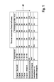
- Fig. 1 shows a tabular comparison of a comparative rotor (not shown) and a conventional rotor (not shown) for sensorless speed measurement, which are not wound with the inventive method, with a rotor 1 (s. Fig. 2 ), which is wound by the method according to the invention.
- the comparative rotor and the rotor for sensorless rotational speed measurement both have the same number of coils 4 and the same number of grooves 30, 31 - 3i, as the invention wound rotor 1.
- the number of conductor loops 5 per groove 30, 31 - 3i of the comparative rotor is equal to
- the average number of conductor loops 5 of each of the three rotors 1 is the same, so that the copper filling factor of the rotors 1 is the same.
- the comparative rotor and the rotor 1 wound according to the invention also au- ⁇ erdem also the same space and have the same weight.
- the missing amount of copper of a conventional rotor would have to be compensated for by additional length and therefore with greater weight and higher costs.
- the rotors 1 selected here have ten grooves 30, 31 - 3i, which are wound with five coils 4, which are designed here as double coils.
- a double coil is formed from two winding strands.
- each coil 4 is wound from a total of fifty conductor loops 5, each consisting of two winding strands, each with twenty-five conductor loops 5.
- the conventional rotor for sensorless speed measurement has the same total number of conductor loops 5, namely two hundred and fifty conductor loops 5. But the number of conductor loops 5 per coil 4 varies, so that with a minimum number of forty-four conductor loops 5 of the smallest coil 4, the largest coil 4 fifty-six conductor loops 5 has.
- the inventively wound rotor 1 has coils 4 with the same number of conductor loops 5 per coil 4, as the conventional rotor for sensorless speed measurement.
- the starting point when winding the rotor 1 is selected so that the last-wound coil 4 has a number of conductors 5 whose number of conductor loops 5 is less than or equal to the average number of conductor loops 5 of all coils 4, and their number of conductor loops 5 therefore the number of conductor loops 5 per coil 4 of the comparative rotor corresponds.
- the number of conductor loops 5 per coil 4 of the last wound coil 4 is preferably as small as possible, so that it is particularly preferred to wind the smallest coil 4 last.
- the order in which the coils 4 are wound preferably does not change. But it is preferable to change only the end point or the starting point.
- the winding order of the coils 4 is indicated in the table by an arrow 20.
- Fig. 2 shows a rotor 1, which extends along a shaft 12, and which is wound by the method according to the invention. And that shows Fig. 2a the Strinseite of the rotor 1 and the Fig. 2b a side view.
- the rotor 1 has ten poles 2, between which ten grooves 30, 31 - 3i are arranged. In the grooves 30, 31 - 3i coils 4 are wound, which have a different number of conductor loops 5 per coil 4.
- the coils 4 are electrically connected to commutator bars 6 of a commutator 7.
- the rotor 1 has an end face 11, via which the conductor loops 5 extend from one groove 30, 31-3i of the rotor 1 to another groove 30, 31-3i of the rotor 1.
- the other groove 30, 31 - 3i not that of a groove 30, 31 - 3i immediately adjacent groove 30, 31 - wound 3i, but for electromagnetic reasons one of the one groove 30, 31 - 3i remote groove 30, 31 3i.
- the coils 4 each extend from one groove 30, 31 - 3i in the next but one other groove 30, 31 - 3i.
- the end point or the starting point of the wound coil 4 is chosen so that the last wound coil 4 is as small as possible and the number of average conductor loops 5 of all coil 4 does not exceed the slot openings 13 for the last wound coil 4 despite the partially larger Number of conductors 5 per coil 4 with the same available groove space compared to a comparison rotor (not shown) large enough to wind the last wound coil 4, since the adjacent coils 4 are correspondingly smaller due to their smaller number of conductor loops 5.
Abstract
Description
Die vorliegende Erfindung betrifft einen Rotor für eine elektrische Maschine, der Nuten aufweist, in denen Leiterschleifen angeordnet sind, die Spulen ausbilden, und der Kommutatorlamellen eines Kommutators aufweist, die zum Beaufschlagen der Spulen mit einem elektrischen Strom mit diesen elektrisch verbunden sind, wobei die Anzahl der Leiterschleifen pro Nut variabel gewählt ist. Die vorliegende Erfindung betrifft weiterhin ein Verfahren zum Herstellen der Wicklung des Rotors.The present invention relates to a rotor for an electric machine having grooves in which conductor loops are arranged, forming the coils, and the Kommutatorlamellen a commutator, which are electrically connected for applying the coils with an electric current thereto, wherein the number the conductor loops per groove is chosen variable. The present invention further relates to a method for producing the winding of the rotor.
Herkömmlich weisen elektrische Maschinen einen Rotor mit Spulen auf, die alle dieselbe Anzahl Leiterschleifen aufweisen. Um sensorlos ein Drehzahlsignal zu erzeugen, ist es aus der Druckschrift
Es hat sich jedoch gezeigt, dass ein Rotor für sensorlose Drehzahlmessung mit unterschiedlicher Anzahl Leiterschleifen pro Nut, nicht auf herkömmliche Art und Weise wickelbar ist, da er Spulen umfasst, die eine höhere Anzahl Leiterschleifen aufweisen, als ein Vergleichsrotor mit derselben Anzahl Spulen, die alle dieselbe Leiterschleifenanzahl aufweisen, so dass der zwischen den Polen des Rotors zur Verfügung stehende Nutraum für den Rotor für sensorlose Drehzahlmessung nicht ausreicht.However, it has been found that a rotor for sensorless rotational speed measurement with different number of conductor loops per groove, can not be wound in a conventional manner, since it comprises coils having a higher number of conductor loops, as a comparison rotor with the same number of coils, all have the same number of conductor loops, so that the between the poles of the rotor to Available slot space for the rotor for sensorless speed measurement is not sufficient.
Aufgabe der Erfindung ist es, einen Rotor für eine elektrische Maschine sowie ein Verfahren zur Herstellung seiner Wicklung zu schaffen, wobei der Rotor Spulen mit einer unterschiedlichen Anzahl Leiterschleifen pro Spule aufweist und dennoch dieselbe Baugröße aufweist, wie ein Vergleichsrotor mit derselben Anzahl Spulen, die alle dieselbe Anzahl Leiterschleifen pro Spule aufweisen.The object of the invention is to provide a rotor for an electric machine and a method for producing its winding, wherein the rotor has coils with a different number of conductor loops per coil and yet has the same size as a comparison rotor with the same number of coils, all have the same number of conductor loops per coil.
Die Aufgabe wird gelöst mit einem Verfahren zum Herstellen eines Rotors für eine elektrische Maschine, der Nuten aufweist, in denen Leiterschleifen angeordnet sind, die Spulen ausbilden, wobei die Anzahl der Leiterschleifen pro Nut variabel gewählt ist, wobei das Bewickeln der Nuten mit den Leiterschleifen so ausgeführt wird, dass die Anzahl der Leiterschleifen der zuletzt gewickelten Spule kleiner oder gleich einer durchschnittlichen Anzahl der Leiterschleifen aller bewickelten Spulen des Rotors ist.The object is achieved with a method for producing a rotor for an electrical machine having grooves in which conductor loops are arranged which form coils, wherein the number of conductor loops per groove is variably selected, wherein the winding of the grooves with the conductor loops so is carried out that the number of conductor loops of the last wound coil is less than or equal to an average number of conductor loops of all wound coils of the rotor.
Es hat sich gezeigt, dass ein Rotor mit unterschiedlicher Anzahl Leiterschleifen pro Nut herstellbar ist, der dieselbe Baugröße aufweist, insbesondere dasselbe Gewicht und einen identischen Bauraum einnimmt, wie ein Vergleichsrotor mit derselben Anzahl Spulen und derselben Anzahl Leiterschleifen pro Nut, indem die zuletzt gewickelte Spule die durchschnittliche Anzahl der Leiterschleifen aller bewickelten Spulen nicht überschreitet. Bevorzugt weist die zuletzt gewickelte Spule jedoch die kleinste Anzahl Leiterschleifen der Spulen des Rotors auf.It has been found that a rotor with different number of conductor loops per groove can be produced, which has the same size, in particular the same weight and an identical space occupies, as a comparison rotor with the same number of coils and the same number of conductor loops per groove, by the last-wound coil does not exceed the average number of conductor loops of all wound coils. However, the last-wound coil preferably has the smallest number of conductor loops of the coils of the rotor.
Es ist weiterhin bevorzugt, dass sich die Reihenfolge, in der die Spulen gewickelt werden, nicht ändert.It is further preferred that the order in which the coils are wound does not change.
Der erfindungsgemäß gewickelte Rotor weist denselben Kupferfüllfaktor auf, wie ein Vergleichsrotor mit derselben Anzahl Spulen, die alle dieselbe Anzahl Leiterschleifen pro Spule aufweisen, wobei die Anzahl Leiterschleifen pro Spule der durchschnittlichen Anzahl der Leiterschleifen des erfindungsgemäßen Rotors entspricht. Der erfindungsgemäß gewickelte Rotor ist außerdem für dieselben Herstellungskosten fertigbar, oder aufgrund der nicht benötigten Sensorbauteile sogar kostengünstiger. Im Vergleich zu einem herkömmlich bewickelten Rotor für sensorlose Drehzahlmessung mit unterschiedlicher Anzahl Leiterschleifen pro Spule und derselben Anzahl Spulen ist der erfindungsgemäß gewickelte Rotor kürzer und somit kostengünstiger herstellbar.The rotor wound in accordance with the invention has the same copper fill factor as a comparative rotor with the same number of coils, all having the same number of conductor loops per coil, the number of conductor loops per coil being the average number of conductor loops of the rotor according to the invention equivalent. The inventively wound rotor is also manufacturable for the same manufacturing cost, or even cheaper due to the unnecessary sensor components. In comparison to a conventionally wound rotor for sensorless rotational speed measurement with different number of conductor loops per coil and the same number of coils, the rotor wound according to the invention is shorter and thus less expensive to produce.
Die Aufgabe wird weiterhin gelöst mit einem Rotor, der nach dem erfindungsgemäßen Verfahren hergestellt ist. Der Rotor weist Nuten auf, in denen Leiterschleifen angeordnet sind, die Spulen ausbilden. Er hat den Vorteil, dass er denselben Kupferfüllfaktor aufweist, wie ein Vergleichsrotor mit derselben Anzahl Spulen, wobei die Anzahl der Leiterschleifen der Spulen des Vergleichsrotors gleich der durchschnittlichen Anzahl der Leiterschleifen aller bewickelten Spulen des Rotors ist.The object is further achieved with a rotor which is produced by the process according to the invention. The rotor has grooves in which conductor loops are arranged which form coils. It has the advantage of having the same copper fill factor as a comparative rotor with the same number of coils, with the number of conductor loops of the coils of the reference rotor being equal to the average number of conductor loops of all the wound coils of the rotor.
Bevorzugt weist der Rotor außerdem Kommutatorlamellen eines Kommutators auf, die zum Beaufschlagen der Spulen mit einem elektrischen Strom mit diesen elektrisch leitend verbunden sind. Dabei ist die Anzahl der Leiterschleifen pro Nut erfindungsgemäß variabel gewählt.Preferably, the rotor also has commutator bars of a commutator, which are electrically connected to the coils for applying an electric current to them. The number of conductor loops per groove is variably chosen according to the invention.
Es ist außerdem bevorzugt, dass die Abfolge der Anzahl der Leiterschleifen der Spulen des Rotors in der Reihenfolge ihrer Kommutierung näherungsweise eine Sinusfunktion darstellt. Denn ein mit einem solchen Rotor erzeugtes Motorstromsignal ist mit einer Auswerteeinheit so auswertbar, dass aus dem Motorstromsignal die Drehzahl sowie die Drehposition des Rotors bestimmbar sind.It is also preferred that the sequence of the number of conductor loops of the coils of the rotor in the order of their commutation represents approximately a sinusoidal function. For a motor current signal generated with such a rotor can be evaluated with an evaluation unit so that the speed and the rotational position of the rotor can be determined from the motor current signal.
Die Aufgabe wird weiterhin gelöst mit einer elektrischen Maschine mit einem solchen Rotor. Die elektrische Maschine ist bevorzugt ein Elektromotor, der einen Stator und einen Rotor aufweist. Besonders bevorzugt ist der Elektromotor ein Stellmotor zum Verstellen von Teilen, insbesondere eines Kraftfahrzeugs, beispielsweise von Fensterscheiben oder Sitzen.The object is further achieved with an electric machine with such a rotor. The electric machine is preferably an electric motor having a stator and a rotor. Particularly preferably, the electric motor is a servo motor for adjusting parts, in particular of a motor vehicle, for example windows or seats.
Im Folgenden wird die Erfindung anhand von Figuren beschrieben. Die Figuren sind lediglich beispielhaft und schränken den allgemeinen Erfindungsgedanken nicht ein.
- Fig. 1
- zeigt tabellarisch einen Vergleich verschiedener Rotoren, die nicht mit dem erfindungsgemäßen Verfahren bewickelt sind, mit einem Rotor, der nach dem erfindungsgemäßen Verfahren bewickelt ist,
- Fig. 2
- zeigt einen Rotor, der nach dem erfindungsgemäßen Verfahren bewickelt ist.
- Fig. 1
- shows in tabular form a comparison of different rotors, which are not wound with the method according to the invention, with a rotor, which is wound by the method according to the invention,
- Fig. 2
- shows a rotor which is wound by the method according to the invention.
Der Vergleichsrotor sowie der Rotor für sensorlose Drehzahlmessung weisen beide dieselbe Anzahl Spulen 4 und dieselbe Anzahl Nuten 30, 31 - 3i auf, wie der erfindungsgemäß bewickelte Rotor 1. Außerdem ist die Anzahl der Leiterschleifen 5 pro Nut 30, 31 - 3i des Vergleichsrotors gleich der durchschnittlichen Anzahl der Leiterschleifen 5 aller Spulen 4 sowohl des Rotors für sensorlose Drehzahlmessung als auch des erfindungsgemäß bewickelten Rotors 1. Daher ist die Gesamtzahl aller Leiterschleifen 5 jeder der drei Rotoren 1 gleich, so dass der Kupferfüllfaktor der Rotoren 1 gleich ist.The comparative rotor and the rotor for sensorless rotational speed measurement both have the same number of
Der Vergleichsrotor sowie der erfindungsgemäß bewickelte Rotor 1 nehmen au-βerdem auch denselben Bauraum ein und weisen dasselbe Gewicht auf. Im Vergleich dazu müsste die fehlende Kupfermenge eines herkömmlichen Rotors durch zusätzliche Baulänge und daher mit größerem Gewicht und höheren Kosten kompensiert werden.The comparative rotor and the
Die hier gewählten Rotoren 1 weisen zehn Nuten 30, 31 - 3i auf, die mit fünf Spulen 4, die hier als Doppelspulen ausgebildet sind, bewickelt sind. Eine Doppelspule ist aus zwei Wickelsträngen gebildet.The
Beim Vergleichsrotor ist jede Spule 4 aus insgesamt fünfzig Leiterschleifen 5 gewickelt, die jeweils aus zwei Wickelsträngen mit jeweils fünfundzwanzig Leiterschleifen 5 bestehen.In the comparison rotor each
Der herkömmliche Rotor für sensorlose Drehzahlmessung weist zwar dieselbe Gesamtzahl Leiterschleifen 5 auf, nämlich zweihundertfünfzig Leiterschleifen 5. Aber die Anzahl der Leiterschleifen 5 pro Spule 4 variiert, so dass bei einer minimalen Anzahl von vierundvierzig Leiterschleifen 5 der kleinsten Spule 4 die größte Spule 4 sechsundfünfzig Leiterschleifen 5 aufweist.Although the conventional rotor for sensorless speed measurement has the same total number of
Der erfindungsgemäß bewickelte Rotor 1 weist Spulen 4 mit der gleichen Anzahl Leiterschleifen 5 pro Spule 4 auf, wie der herkömmliche Rotor für sensorlose Drehzahlmessung. Jedoch ist der Startpunkt beim Bewickeln des Rotors 1 so gewählt, dass die zuletzt gewickelte Spule 4 eine Leiterzahl 5 aufweist, deren Anzahl Leiterschleifen 5 kleiner oder gleich der durchschnittlichen Anzahl der Leiterschleifen 5 aller Spulen 4 ist, und deren Anzahl Leiterschleifen 5 daher der Anzahl Leiterschleifen 5 pro Spule 4 des Vergleichsrotors entspricht. Die Anzahl der Leiterschleifen 5 pro Spule 4 der zuletzt gewickelten Spule 4 ist bevorzugt möglichst klein, so dass es besonders bevorzugt ist, die kleinste Spule 4 zuletzt zu bewickeln.The
Im Vergleich zu einem Rotor für sensorlose Drehzahlmessung ändert sich die Reihenfolge, in der die Spulen 4 gewickelt werden, bevorzugt nicht. Sondern es ist bevorzugt, lediglich den Endpunkt beziehungsweise den Startpunkt zu verändern. Die Wickelreihenfolge der Spulen 4 ist in der Tabelle mit einem Pfeil 20 gekennzeichnet.In comparison to a rotor for sensorless rotational speed measurement, the order in which the
Der Rotor 1 weist eine Stirnseite 11 auf, über die sich die Leiterschleifen 5 von einer Nut 30, 31 - 3i des Rotors 1 zu einer anderen Nut 30, 31 - 3i des Rotors 1 erstrecken. Dabei wird als andere Nut 30, 31 - 3i nicht die der einen Nut 30, 31 - 3i unmittelbar benachbarte Nut 30, 31 - 3i bewickelt, sondern aus elektromagnetischen Gründen eine von der einen Nut 30, 31 - 3i entfernte Nut 30, 31 - 3i. Im vorliegenden Ausführungsbeispiel erstrecken sich die Spulen 4 jeweils von der einen Nut 30, 31 - 3i in die übernächste andere Nut 30, 31 - 3i.The
Dabei überdecken die Leiterschleifen 5 der von der einen Nut 30, 31 - 3i zur übernächsten anderen Nut 30, 31 - 3i gewickelten Spule 4 eine Nutöffnung 13 der benachbarten Nut 30, 31 - 3i teilweise.Here, the conductor loops 5 of the one groove 30, 31 - 3i to the next but one other groove 30, 31 - wound 3i coil 4 a groove opening 13 of the adjacent groove 30, 31 - 3i partially.
Indem der Endpunkt beziehungsweise der Startpunkt der gewickelten Spulen 4 so gewählt wird, dass die zuletzt gewickelte Spule 4 möglichst klein ist und die Anzahl der durchschnittlichen Leiterschleifen 5 aller Spule 4 nicht übersteigt, sind die Nutöffnungen 13 für die zuletzt gewickelte Spule 4 trotz der teilweise größeren Leiterzahl 5 pro Spule 4 bei gleichem zur Verfügung stehendem Nutraum im Vergleich zu einem Vergleichsrotor (nicht dargestellt) groß genug, um die zuletzt gewickelte Spule 4 wickeln zu können, da die benachbarten Spulen 4 aufgrund ihrer geringeren Anzahl Leiterschleifen 5 entsprechend kleiner sind.By the end point or the starting point of the
Claims (6)
dadurch gekennzeichnet, dass
das Bewickeln der Nuten (30, 31 - 3i) mit den Leiterschleifen (5) so ausgeführt wird, dass die Anzahl der Leiterschleifen (5) der zuletzt gewickelten Spule (4) kleiner oder gleich einer durchschnittlichen Anzahl der Leiterschleifen (30, 31 - 3i) aller bewickelten Spulen (4) des Rotors (1) ist.Method for producing a winding of a rotor (1) for an electrical machine, having grooves (30, 31 - 3i) in which conductor loops (5) of the winding are arranged, forming coils (4), the number of conductor loops ( 5) is variably selected per groove (30, 31 - 3i),
characterized in that
the winding of the grooves (30, 31-3i) with the conductor loops (5) is carried out such that the number of conductor loops (5) of the last wound coil (4) is less than or equal to an average number of conductor loops (30, 31-3i ) of all wound coils (4) of the rotor (1).
Applications Claiming Priority (1)
| Application Number | Priority Date | Filing Date | Title |
|---|---|---|---|
| DE102010042651A DE102010042651A1 (en) | 2010-10-20 | 2010-10-20 | Rotor with maximum copper fill factor |
Publications (2)
| Publication Number | Publication Date |
|---|---|
| EP2445091A2 true EP2445091A2 (en) | 2012-04-25 |
| EP2445091A3 EP2445091A3 (en) | 2017-06-14 |
Family
ID=44838203
Family Applications (1)
| Application Number | Title | Priority Date | Filing Date |
|---|---|---|---|
| EP11181856.3A Withdrawn EP2445091A3 (en) | 2010-10-20 | 2011-09-19 | Rotor with maximum fill factor |
Country Status (2)
| Country | Link |
|---|---|
| EP (1) | EP2445091A3 (en) |
| DE (1) | DE102010042651A1 (en) |
Families Citing this family (1)
| Publication number | Priority date | Publication date | Assignee | Title |
|---|---|---|---|---|
| DE102013223785B4 (en) | 2013-11-21 | 2018-08-09 | Robert Bosch Gmbh | Method for producing a rotor for an electric machine and rotor for an electric machine and electric machine |
Citations (1)
| Publication number | Priority date | Publication date | Assignee | Title |
|---|---|---|---|---|
| DE102007036253A1 (en) | 2007-08-02 | 2009-02-05 | Robert Bosch Gmbh | Electric machine with conductor loops arranged in grooves, and method for operating the electrical machine |
Family Cites Families (3)
| Publication number | Priority date | Publication date | Assignee | Title |
|---|---|---|---|---|
| JPH0734630B2 (en) * | 1990-11-08 | 1995-04-12 | アスモ株式会社 | Winding method for rotating armature |
| JP3482360B2 (en) * | 1999-09-27 | 2003-12-22 | 株式会社ミツバ | Motor rotation detection structure |
| BRPI1009492A8 (en) * | 2009-03-16 | 2016-10-11 | Brose Fahrzeugteile | correction of counting errors in the evaluation of current ripples in a direct current motor |
-
2010
- 2010-10-20 DE DE102010042651A patent/DE102010042651A1/en not_active Ceased
-
2011
- 2011-09-19 EP EP11181856.3A patent/EP2445091A3/en not_active Withdrawn
Patent Citations (1)
| Publication number | Priority date | Publication date | Assignee | Title |
|---|---|---|---|---|
| DE102007036253A1 (en) | 2007-08-02 | 2009-02-05 | Robert Bosch Gmbh | Electric machine with conductor loops arranged in grooves, and method for operating the electrical machine |
Also Published As
| Publication number | Publication date |
|---|---|
| DE102010042651A1 (en) | 2012-04-26 |
| EP2445091A3 (en) | 2017-06-14 |
Similar Documents
| Publication | Publication Date | Title |
|---|---|---|
| EP1745541A1 (en) | Commutator motor having a number of field winding groups | |
| EP2052455B1 (en) | Electrical machine with single-tooth rotor winding | |
| EP3347973B1 (en) | Stator for an electric machine, electric machine and manufacturing method | |
| DE102006011550A1 (en) | Electric machine | |
| EP1997215B1 (en) | Electrical machine | |
| DE202017107388U1 (en) | Multi-tooth coil winding for a 3-phase induction machine | |
| WO2009000586A2 (en) | Winding body for an electric motor and method for producing a winding body for an electric motor | |
| EP1997212A1 (en) | Electrical machine | |
| DE19757279C9 (en) | Commutator motor, in particular for driving a motor vehicle servo drive, and method for its production | |
| DE102007036253A1 (en) | Electric machine with conductor loops arranged in grooves, and method for operating the electrical machine | |
| EP3357141B1 (en) | Stator or rotor, which is produced using a plug-in technology method, of an electrical machine with a reduced lamination length | |
| DE10114014A1 (en) | Electrical 3-phase machine e.g. for machine tools, has six poles, stator packet, rotor, winding heads on the ends of the stator packet, stator grooves, an upper layer and a lower layer | |
| DE10051621A1 (en) | Induction motor (asynchronous motor) with pole switching has stator with group(s) of first winding with 2n poles, second with 2m poles on same stator core, m=2kn and k is a natural number | |
| DE102007038601A1 (en) | Electric machine with a winding for generating a rotating field and method for producing the winding | |
| EP1671411A1 (en) | Electric machine stator | |
| EP2445091A2 (en) | Rotor with maximum fill factor | |
| WO2010145841A2 (en) | Stator for an electric motor | |
| DE102017128832A1 (en) | Multi-tooth coil winding for a 3-phase induction machine | |
| DE102006035699A1 (en) | Machine winding e.g. stator winding, manufacturing method for electrical multi phase machine, involves manufacturing machine winding by windings, and winding single windings for poles of phase with conductive material | |
| DE102013223785B4 (en) | Method for producing a rotor for an electric machine and rotor for an electric machine and electric machine | |
| DE102006024520B4 (en) | Arrangement with a winding for an electrical machine | |
| WO2014184180A2 (en) | Brush-commutated direct-current motor | |
| DE2603282C3 (en) | Method for producing a two-layer Dahlander winding for an electrical machine | |
| DE102012215735A1 (en) | Electrical commutator motor for electromotive seat adjuster in passenger compartment of motor car, has anchor teeth arranged at armature periphery, and winding provided on each tooth as single-tooth winding and formed as two-fold winding | |
| DE102018113722A1 (en) | Stand for an electric machine with six phase windings and electric machine |
Legal Events
| Date | Code | Title | Description |
|---|---|---|---|
| AK | Designated contracting states |
Kind code of ref document: A2 Designated state(s): AL AT BE BG CH CY CZ DE DK EE ES FI FR GB GR HR HU IE IS IT LI LT LU LV MC MK MT NL NO PL PT RO RS SE SI SK SM TR |
|
| AX | Request for extension of the european patent |
Extension state: BA ME |
|
| PUAI | Public reference made under article 153(3) epc to a published international application that has entered the european phase |
Free format text: ORIGINAL CODE: 0009012 |
|
| PUAL | Search report despatched |
Free format text: ORIGINAL CODE: 0009013 |
|
| AK | Designated contracting states |
Kind code of ref document: A3 Designated state(s): AL AT BE BG CH CY CZ DE DK EE ES FI FR GB GR HR HU IE IS IT LI LT LU LV MC MK MT NL NO PL PT RO RS SE SI SK SM TR |
|
| AX | Request for extension of the european patent |
Extension state: BA ME |
|
| RIC1 | Information provided on ipc code assigned before grant |
Ipc: H02K 23/26 20060101AFI20170508BHEP Ipc: H02K 3/28 20060101ALI20170508BHEP |
|
| STAA | Information on the status of an ep patent application or granted ep patent |
Free format text: STATUS: THE APPLICATION IS DEEMED TO BE WITHDRAWN |
|
| 18D | Application deemed to be withdrawn |
Effective date: 20171215 |