EP2445058B1 - Ensemble de connecteur électrique - Google Patents
Ensemble de connecteur électrique Download PDFInfo
- Publication number
- EP2445058B1 EP2445058B1 EP10380127.0A EP10380127A EP2445058B1 EP 2445058 B1 EP2445058 B1 EP 2445058B1 EP 10380127 A EP10380127 A EP 10380127A EP 2445058 B1 EP2445058 B1 EP 2445058B1
- Authority
- EP
- European Patent Office
- Prior art keywords
- complementary
- base body
- channels
- connector assembly
- different
- Prior art date
- Legal status (The legal status is an assumption and is not a legal conclusion. Google has not performed a legal analysis and makes no representation as to the accuracy of the status listed.)
- Active
Links
- 230000000295 complement effect Effects 0.000 claims description 58
- 239000004020 conductor Substances 0.000 claims description 26
- 238000004891 communication Methods 0.000 claims description 4
- 230000005489 elastic deformation Effects 0.000 claims description 3
- 238000011084 recovery Methods 0.000 claims description 3
- 230000008878 coupling Effects 0.000 description 3
- 238000010168 coupling process Methods 0.000 description 3
- 238000005859 coupling reaction Methods 0.000 description 3
- 239000000463 material Substances 0.000 description 2
- 238000000465 moulding Methods 0.000 description 2
- 230000000712 assembly Effects 0.000 description 1
- 238000000429 assembly Methods 0.000 description 1
- 230000001419 dependent effect Effects 0.000 description 1
- 230000013011 mating Effects 0.000 description 1
- 238000000034 method Methods 0.000 description 1
- 238000012986 modification Methods 0.000 description 1
- 230000004048 modification Effects 0.000 description 1
Images


Classifications
-
- H—ELECTRICITY
- H01—ELECTRIC ELEMENTS
- H01R—ELECTRICALLY-CONDUCTIVE CONNECTIONS; STRUCTURAL ASSOCIATIONS OF A PLURALITY OF MUTUALLY-INSULATED ELECTRICAL CONNECTING ELEMENTS; COUPLING DEVICES; CURRENT COLLECTORS
- H01R13/00—Details of coupling devices of the kinds covered by groups H01R12/70 or H01R24/00 - H01R33/00
- H01R13/46—Bases; Cases
- H01R13/502—Bases; Cases composed of different pieces
- H01R13/506—Bases; Cases composed of different pieces assembled by snap action of the parts
-
- H—ELECTRICITY
- H01—ELECTRIC ELEMENTS
- H01R—ELECTRICALLY-CONDUCTIVE CONNECTIONS; STRUCTURAL ASSOCIATIONS OF A PLURALITY OF MUTUALLY-INSULATED ELECTRICAL CONNECTING ELEMENTS; COUPLING DEVICES; CURRENT COLLECTORS
- H01R13/00—Details of coupling devices of the kinds covered by groups H01R12/70 or H01R24/00 - H01R33/00
- H01R13/46—Bases; Cases
- H01R13/514—Bases; Cases composed as a modular blocks or assembly, i.e. composed of co-operating parts provided with contact members or holding contact members between them
-
- H—ELECTRICITY
- H01—ELECTRIC ELEMENTS
- H01R—ELECTRICALLY-CONDUCTIVE CONNECTIONS; STRUCTURAL ASSOCIATIONS OF A PLURALITY OF MUTUALLY-INSULATED ELECTRICAL CONNECTING ELEMENTS; COUPLING DEVICES; CURRENT COLLECTORS
- H01R27/00—Coupling parts adapted for co-operation with two or more dissimilar counterparts
-
- H—ELECTRICITY
- H01—ELECTRIC ELEMENTS
- H01R—ELECTRICALLY-CONDUCTIVE CONNECTIONS; STRUCTURAL ASSOCIATIONS OF A PLURALITY OF MUTUALLY-INSULATED ELECTRICAL CONNECTING ELEMENTS; COUPLING DEVICES; CURRENT COLLECTORS
- H01R13/00—Details of coupling devices of the kinds covered by groups H01R12/70 or H01R24/00 - H01R33/00
- H01R13/02—Contact members
- H01R13/10—Sockets for co-operation with pins or blades
- H01R13/11—Resilient sockets
- H01R13/113—Resilient sockets co-operating with pins or blades having a rectangular transverse section
-
- H—ELECTRICITY
- H01—ELECTRIC ELEMENTS
- H01R—ELECTRICALLY-CONDUCTIVE CONNECTIONS; STRUCTURAL ASSOCIATIONS OF A PLURALITY OF MUTUALLY-INSULATED ELECTRICAL CONNECTING ELEMENTS; COUPLING DEVICES; CURRENT COLLECTORS
- H01R13/00—Details of coupling devices of the kinds covered by groups H01R12/70 or H01R24/00 - H01R33/00
- H01R13/40—Securing contact members in or to a base or case; Insulating of contact members
- H01R13/42—Securing in a demountable manner
- H01R13/428—Securing in a demountable manner by resilient locking means on the contact members; by locking means on resilient contact members
- H01R13/432—Securing in a demountable manner by resilient locking means on the contact members; by locking means on resilient contact members by stamped-out resilient tongue snapping behind shoulder in base or case
-
- H—ELECTRICITY
- H01—ELECTRIC ELEMENTS
- H01R—ELECTRICALLY-CONDUCTIVE CONNECTIONS; STRUCTURAL ASSOCIATIONS OF A PLURALITY OF MUTUALLY-INSULATED ELECTRICAL CONNECTING ELEMENTS; COUPLING DEVICES; CURRENT COLLECTORS
- H01R33/00—Coupling devices specially adapted for supporting apparatus and having one part acting as a holder providing support and electrical connection via a counterpart which is structurally associated with the apparatus, e.g. lamp holders; Separate parts thereof
- H01R33/74—Devices having four or more poles, e.g. holders for compact fluorescent lamps
- H01R33/76—Holders with sockets, clips, or analogous contacts adapted for axially-sliding engagement with parallely-arranged pins, blades, or analogous contacts on counterpart, e.g. electronic tube socket
- H01R33/7671—Holders with sockets, clips, or analogous contacts adapted for axially-sliding engagement with parallely-arranged pins, blades, or analogous contacts on counterpart, e.g. electronic tube socket having multiple positions or sockets, e.g. stacked sockets while mounting
Definitions
- the present invention generally relates to an electrical connector assembly and more particularly to an electrical connector assembly to be used with a plurality of conductor wires and an electrical device.
- a well known case is the typical push-button switch with a small built-in lamp such as the one described in document US-A-5543594 which essentially comprises a connecting block having a miniature push-button type electrical switch with a small built-in lamp, which comprises a push-button with a translucent cover and a housing in which said push-button is seated.
- a tubular part of the housing is externally threaded for coupling a nut to the switch.
- a pushing member is fixed to the button for the purpose of acting on the microswitch.
- At the opposite part of the push-button there are pins or terminals for the connection thereof to suitable conductor wires.
- the mentioned device therefore has an exclusive and very specific application to a small built-in lamp in a push-button type switch.
- Document ES-A-2237335 is also known, which describes a connector for connecting a plurality of conductor wires to a miniature lamp socket and switch assembly, which is similar to the one described in the mentioned document US-A-5543594 , and which has contact tabs and a grounding pin.
- the connector includes a molded one-piece casing and a plurality of terminals for attaching the plurality of conductor wires to the contact tabs and the grounding pin.
- a plurality of openings are formed inside the casing, accepting the plurality of terminals as well as the contact tabs and the grounding pin of the assembly, and allowing the terminals to be connected to the contact tabs and the grounding pin.
- the plurality of openings are formed on the lower, front and rear faces of the casing.
- This document also describes a method for connecting a miniature lamp socket and switch assembly, which is similar to the one described in the mentioned document US-A-5543594 and which comprises contact tabs and a grounding pin to a plurality of conduct
- the device which has just been described has a very specific field of application, namely, a small lamp socket associated with a miniature switch or microswitch.
- Document US 7077708 B1 discloses an electrical connector assembly as disclosed in the preamble of claim 1 comprising a casing having parallel channels in which there are housed a plurality of terminals fixed to respective conductor wires and a plurality of openings in communication with the channels such that contact tabs are connectable with the terminals when the contact tabs are inserted into the openings, wherein the casing is comprised of a base body and a complementary body coupled to one another by releasable fixing means, and wherein each of the parallel channels is constituted from a first channel part formed in the base body and a second channel part formed in the complementary body, the first and second channel parts complementing one another to form together the channels when the base body and the complementary body are coupled to one another.
- Document EP 0854543 A2 discloses a multilevel electrical connector assembly having a casing comprised of a base body and one or optionally two complementary bodies having respective channel parts which complement one another to form parallel channels housing terminals when coupled together, wherein the main body is formed with a common hood or receptacle which accommodates all terminal fittings when the respective bodies are assembled and the common hood or receptacle is engageable with a mating connector housing.
- Document US 2004214472 A1 discloses an electrical connector comprising a one-piece casing having parallel channels in which there are housed a plurality of terminals fixed to respective conductor wires and a plurality of openings in communication with the channels such that contact tabs are connectable with the terminals when the contact tabs are inserted into the openings, wherein the one-piece casing has a substantially parallelepiped configuration, and the channels where terminals are housed have respective inlets in a front face of the one-piece casing and the openings to receive the contact tabs are located in an upper face of the one-piece casing perpendicular to the front face.
- the present invention provides an electrical connector assembly as disclosed in independent claim 1 and dependent claims 2 to 5.
- said guide members comprise at least one guide groove formed in one of the base body and complementary body and at least one guide flange formed in the other one of the base body and complementary body.
- the mentioned guide groove and guide flange are mutually coupled and cooperate to allow a relative sliding of the base body and complementary body in a direction parallel to the first channels.
- the mentioned positioning members comprise, for example, respective stop surfaces positioned to make mutual contact when the base body and complementary body are in a predetermined relative position
- the retaining members comprise, for example, a protrusion in the form of a hook projecting from an elastic arm formed in one of the base body and complementary body and configured to be locked by elastic deformation and recovery of said arm in a recessed step formed in the other one of the base body and complementary body when both are slid with respect to one another and reach said predetermined relative position.
- An advantage of the electrical connector assembly of the present invention is that it can include a variety of different complementary bodies adapted for different functions, which can be individually coupled to the base body to form different connector casings adapted to different uses.
- the second channels of the second body are preferably parallel to the first channels of the base body and are located at a different level, and said second openings of the second body are separated from said first openings of the base body and located at a different level when the base body and complementary body are mutually coupled in said predetermined relative position.
- the connector casing of this invention is useful, for example, for connecting an electrical device such as an assembly formed by a miniature switch or microswitch and a lamp socket equipped with a small lamp similar to the one described in the mentioned document US-A-5543594 .
- the electrical connector assembly of the present invention is more versatile than those known in the prior art, because while the latter, and particularly the connector described in the mentioned document ES-A-2237335 , which has a molded one-piece casing, are configured to invariably receive a small lamp with a push-button switch or a socket for a small lamp and switch, respectively, the electrical connector assembly of the present invention allows forming several different casings by coupling a base body and a complementary body selected from a plurality of different complementary bodies to receive different electrical devices, for example a switch, a lamp socket, or a lamp socket and switch assembly, among others.
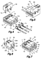
- Figs. 4 and 5 show an electrical connector assembly according to a first embodiment of the present invention, being used with a plurality of conductor wires 8a and an electrical device such as a miniature switch or microswitch 60.
- This electrical connector assembly of the first embodiment comprises a casing 40 (shown in Fig. 3 ), which is formed by a base body 10 (shown in Fig. 1 ) and a first complementary body 20 (shown in Fig. 2 ) which are coupled to one another.
- the base body 10 and first complementary body 20 are obtained by molding an electrically insulating plastic material.
- Figs. 8 and 9 show an electrical connector assembly according to the main embodiment of the present invention, being used with a plurality of conductor wires 8a and an electrical device such as an assembly formed by a miniature switch or microswitch 60 and a lamp socket 70 equipped with a small lamp 71.
- This electrical connector assembly of the second embodiment comprises a casing 50 (shown in Fig. 7 ), which is formed by the same base body 10 (shown in Fig. 1 ) and another second complementary body 30 (shown in Fig. 6 ) which are coupled to one another.
- Said second complementary body 30 is also obtained by molding an electrically insulating plastic material.
- the base body 10 has a substantially parallelepiped configuration, with an upper face 10m, two side faces 10c, a front face 10f and a rear face 10t (according to the orientation shown in Fig. 1 ).
- On said upper face 10m there is a central recess 2 having an inlet through the front face 10f of the base body 10, but it does not reach the rear face 10t thereof.
- On both sides of the mentioned central recess 2 there are respective channels 12 with an inlet through said front face 10f. Close to the rear face 10t of the base body 10 there are openings 11 with an inlet through the upper face 10m, and which are communicated with the channels 12.
- first channel part 12a similar to the lower half of the channels 12, and on both sides of said first channel part 12a there are respective guide grooves 4 with an inlet on the front face 10f and which reach up to a first stop surface 13.
- the central recess 2 has prolongations on both sides of the central opening 11 reaching up to the rear face 10t of the base body 10, where it forms respective recessed steps 14.
- the first complementary body 20 of the first embodiment ( Fig. 2 ) and the second complementary body 30 of the main embodiment ( Fig. 6 ) have in common an approximately parallelepiped configuration, of a size smaller than the base body 10, on the lower face of which (according to the orientation shown in Figs. 2 and 6 ) they have formed a second channel part 12b similar to the upper half of the first channels 12 of the base body 10.
- the first and second complementary bodies 20, 30 comprise a second stop surface 23 on their rear faces 20t, 30t which makes contact with the corresponding first stop surface 13 of the base body 10 when the base body 10 and any one of the first and second complementary bodies 20, 30 are in a predetermined relative position.
- the first and second complementary bodies 20, 30 of the first and main embodiments further have in common elastic arms 24a projecting backwardly from their rear faces 20t, 30t. These elastic arms 24a are finished in corresponding protrusions 24 directed outwardly in the form of hooks.
- the elastic arms experience an elastic deformation and recovery and the protrusions 24 are locked in the mentioned recessed steps 14 of the base body 10, thus retaining the first or second complementary body 20, 30 coupled to the base body 10.
- the first channel part 12a of the base body 10 and the second channel part 12b of the first or second complementary body 20, 30 complement one another to form a central channel 12 which is communicated with that of said openings 11 formed on the larger face 10m of the first body located in the central position.
- the first complementary body 20 of the first embodiment does not have more elements than the common elements described above.
- the mentioned casing 40 of the first embodiment which is formed by the base body 10 ( Fig. 1 ) and the first complementary body 20 ( Fig. 2 ) coupled to one another, comprises three channels 12 with an inlet on the front face and which are communicated with three openings 11 with an inlet on the upper face, where the central channel is formed by the first and second channel parts 12a, 12b of the base body 10 and first complementary body 20 which are mutually coupled.
- Fig. 4 illustrates the casing 40 of the first embodiment ( Fig. 3 ), being used to connect an electrical device such as a miniature switch or microswitch 60 and a plurality of conductor wires 8a.
- Each conductor wire is connected to a terminal 7a, and when the conductor wires 8a and their terminals 7a are inserted into the corresponding channels 12; 12a, 12b, the terminals 7a face the corresponding opening 11.
- the mentioned microswitch 60 has contact tabs 9a which, when the microswitch 60 is coupled to the casing 40 of the first embodiment, are inserted into the openings 11 of the base body 10 and are connected with the corresponding terminals 7a, with the result shown from a reverse point of view in Fig. 5 .
- the second complementary body 30 of the main embodiment has, in addition to the common elements described above, a protruding upper part in which there are formed second channels 22 with an inlet on the front face 30f and which are communicated with second openings 21 with an inlet on the upper face 30m.
- the casing 50 of the main embodiment shown in Fig. 7 which is formed by the base body 10 ( Fig. 1 ) and the second complementary body 30 ( Fig. 6 ), comprises three first channels 12 at a lower level and two second channels 22 parallel to the first channels 12 of the base body 10 and located at an upper level (according to the orientation shown in Fig. 7 ).
- the three first channels 12 of the lower level have an inlet on the front face 10f of the base body 10 and are communicated with the three first openings 11 with an inlet on the upper face 10m of the base body 10, where the central channel of the first channels is formed by the first and second channel parts 12a, 12b of the base body 10 and complementary body 30.
- the two second channels 22 of the upper level have an inlet on the front face 30f of the second complementary body 30 and are communicated with the two second openings 21 with an inlet on the upper face of the second complementary body 30.
- Fig. 8 illustrates the mentioned casing 50 of the main embodiment ( Fig. 7 ), being used to connect an electrical device, such as an assembly formed by a microswitch 60 and a lamp socket 70 having a small lamp 71 to first and second conductor wires 8a, 8b.
- the mentioned microswitch 60 has first contact tabs 9a located at a lower level (according to the orientation shown in Fig. 8 ) which must be connected to said first conductor wires 8a and the lamp socket 70 has second contact tabs 9b located at an upper level which must be connected to said second conductor wires 8b.
- Each first conductor wire 8a is connected to a first terminal 7a and each second conductor wire 8b is connected to a second terminal 7b.
- the first terminals 7a face the corresponding first openings 11 of the base body 10
- the second terminals 7b face the corresponding openings 21 of the second complementary body 30.
- the first contact tabs 9a of the microswitch 60 are inserted into the first openings 11 of the base body 10 and are connected with the corresponding first terminals 7a whereas the second contact tabs 9b of the lamp socket 70 are inserted into the second openings 21 of the second complementary body 30 and are connected with the corresponding second terminals 7b, with the result shown from a reverse point of view in Fig. 9 .
- An advantage of the electrical connector assembly of the present invention lies in the fact that it can combine one and the same base body 10 with any one of the second bodies 20 or 30 according to the electrical device which is to be connected.
Claims (5)
- Ensemble de connecteur électrique comportant un boîtier (40,50) ayant des premiers sillons (12) parallèles dans lesquels est logée une pluralité de bornes (7a) fixées respectivement à une pluralité de fils conducteurs (8a), et une pluralité d'ouvertures (11) en communication avec ces premiers sillons (12) et agencés pour y recevoir des languettes de contact (9a) d'un dispositif électrique (60, 70), de sorte que ces languettes de contact (9a) puissent être connectées à ces bornes (7a) lorsqu'elles sont engagées dans ces ouvertures (11), où ce boîtier (40, 50) comporte un corps de base (10) et un corps complémentaire couplés l'un l'autre et où le corps de base (10) a formé en son intérieur au moins une première partie de sillon (12a) et le corps complémentaire a formé en son intérieur au moins une deuxième partie de sillon (12b), ces première et deuxième parties (12a, 12b) de sillon se complétant l'une l'autre pour former ensemble au moins les premiers sillons (12) lorsque le corps de base (10) et le corps complémentaire sont mutuellement couplés, caractérisé en ce que ce corps complémentaire est sélectionné d'une pluralité de corps complémentaires différents (20, 30) adaptés pour des fonctions différentes, cette pluralité de corps complémentaires différents (20, 30) étant individuellement couplés par des moyens de fixation amovibles sur le corps de base (10) pour recevoir des dispositifs électriques différents (60, 70), ces moyens de fixation amovibles comportant des éléments de guidage, des éléments de positionnement et des éléments de rétention formés sur le corps de base (10) et dans chacune des pluralités de corps complémentaires différents (20, 30), respectivement, le corps de base (10) ayant ces ouvertures (11) y étant formées et chaque pluralité de corps complémentaires différents (20, 30) ayant au moins une première partie de sillon (12a) y étant formée, où au moins un d'une pluralité de corps complémentaires différents (30) comprend au moins un deuxième sillon (22) en communication avec une deuxième ouverture (21), ce deuxième sillon (22) étant configuré pour recevoir une borne (7b) connectée à un fil conducteur (8b) et cette deuxième ouverture (21) étant agencée pour recevoir une languette de contact (9b) de ce dispositif électrique (60, 70) de sorte que la languette de contact (9b) peut être connectée à cette borne (7b) lorsqu'elle est engagée dans cette deuxième ouverture (12).
- L'ensemble de connecteur électrique conformément à la revendication 1, caractérisé en ce que ces éléments de guidage comportent au moins une rainure de guidage (4) formée sur un des corps de base (10) et corps complémentaire (20,30) et au moins une bride de guidage (6) formée sur l'autre corps de base (10) et corps complémentaire (20,30), où cette rainure de guidage (4) et la bride de guidage (6) coopèrent pour permettre un coulissement relatif du corps de base (10) et du corps complémentaire (20,30) dans un sens parallèle aux premiers sillons (12).
- L'ensemble de connecteur électrique conformément à la revendication 2, caractérisé en ce que ces éléments de positionnement comportent des surfaces d'arrêt respectives (13,23) positionnées pour établir le contact mutuel lorsque le corps de base (10) et le corps complémentaire (20,30) sont dans une position relative prédéterminée.
- L'ensemble de connecteur électrique conformément à la revendication 3, caractérisé en ce que ces éléments de rétention comportent une bosse (24) se projetant à partir d'un bras élastique (24a) formé sur un des corps de base (10) et corps complémentaire (20, 30) et configurée pour être bloquée par déformation élastique et récupération dans un décrochement creux (14) formé sur l'autre corps de base (10) et corps complémentaire (20, 30) lorsqu'ils sont tous deux dans cette position prédéterminée relative.
- L'ensemble de connecteur électrique conformément à la revendication 1, caractérisé en ce que ce deuxième sillon (22) du corps complémentaire (30) est parallèle aux premier sillons (12) du corps de base (10) et il est situé à un niveau différent et cette deuxième ouverture (21) du corps complémentaire (30) est écartée de ces premières ouvertures (11) du corps de base (10) et située à un niveau différent lorsque le corps de base (10) et le corps complémentaire (30) sont couplés l'un l'autre dans une position prédéterminée relative.
Priority Applications (4)
| Application Number | Priority Date | Filing Date | Title |
|---|---|---|---|
| ES10380127.0T ES2611194T3 (es) | 2010-10-13 | 2010-10-13 | Conjunto conector eléctrico |
| EP10380127.0A EP2445058B1 (fr) | 2010-10-13 | 2010-10-13 | Ensemble de connecteur électrique |
| US13/273,164 US8408947B2 (en) | 2010-10-13 | 2011-10-13 | Electric connector assembly |
| AU2011235992A AU2011235992A1 (en) | 2010-10-13 | 2011-10-13 | Electrical connector assembly |
Applications Claiming Priority (1)
| Application Number | Priority Date | Filing Date | Title |
|---|---|---|---|
| EP10380127.0A EP2445058B1 (fr) | 2010-10-13 | 2010-10-13 | Ensemble de connecteur électrique |
Publications (2)
| Publication Number | Publication Date |
|---|---|
| EP2445058A1 EP2445058A1 (fr) | 2012-04-25 |
| EP2445058B1 true EP2445058B1 (fr) | 2016-08-24 |
Family
ID=43502067
Family Applications (1)
| Application Number | Title | Priority Date | Filing Date |
|---|---|---|---|
| EP10380127.0A Active EP2445058B1 (fr) | 2010-10-13 | 2010-10-13 | Ensemble de connecteur électrique |
Country Status (4)
| Country | Link |
|---|---|
| US (1) | US8408947B2 (fr) |
| EP (1) | EP2445058B1 (fr) |
| AU (1) | AU2011235992A1 (fr) |
| ES (1) | ES2611194T3 (fr) |
Families Citing this family (4)
| Publication number | Priority date | Publication date | Assignee | Title |
|---|---|---|---|---|
| JP5758677B2 (ja) * | 2011-04-05 | 2015-08-05 | 矢崎総業株式会社 | 圧着端子及びジョイントコネクタ |
| ES2675729T3 (es) | 2011-04-12 | 2018-07-12 | F. Hoffmann-La Roche Ag | Dispositivo de conexión |
| US9734965B2 (en) | 2013-09-23 | 2017-08-15 | Industrias Lorenzo, S.A. | Arrangement of pushbutton switches with a programmable display |
| US9531121B1 (en) * | 2016-04-24 | 2016-12-27 | LED Inspirations, LLC | Electrical connector system |
Citations (1)
| Publication number | Priority date | Publication date | Assignee | Title |
|---|---|---|---|---|
| US20040214472A1 (en) * | 2003-04-28 | 2004-10-28 | Irish Kenneth G. | Connector |
Family Cites Families (5)
| Publication number | Priority date | Publication date | Assignee | Title |
|---|---|---|---|---|
| JP2514449Y2 (ja) * | 1990-06-15 | 1996-10-16 | 矢崎総業株式会社 | ヒュ―ズボックス |
| ES2080676B1 (es) | 1994-01-05 | 1998-03-01 | Romero Herrera Ricardo | Interruptor electrico de pulsador, con lampara integrada. |
| JP3262211B2 (ja) * | 1997-01-14 | 2002-03-04 | 住友電装株式会社 | 圧接コネクタ |
| JP2003323932A (ja) * | 2002-05-01 | 2003-11-14 | Yazaki Corp | シールドコネクタ |
| US7077708B1 (en) * | 2006-02-17 | 2006-07-18 | Regal-Beloit Corporation | Connector assembly |
-
2010
- 2010-10-13 ES ES10380127.0T patent/ES2611194T3/es active Active
- 2010-10-13 EP EP10380127.0A patent/EP2445058B1/fr active Active
-
2011
- 2011-10-13 US US13/273,164 patent/US8408947B2/en not_active Expired - Fee Related
- 2011-10-13 AU AU2011235992A patent/AU2011235992A1/en not_active Abandoned
Patent Citations (1)
| Publication number | Priority date | Publication date | Assignee | Title |
|---|---|---|---|---|
| US20040214472A1 (en) * | 2003-04-28 | 2004-10-28 | Irish Kenneth G. | Connector |
Also Published As
| Publication number | Publication date |
|---|---|
| AU2011235992A1 (en) | 2012-05-03 |
| US8408947B2 (en) | 2013-04-02 |
| EP2445058A1 (fr) | 2012-04-25 |
| US20120094545A1 (en) | 2012-04-19 |
| ES2611194T3 (es) | 2017-05-05 |
Similar Documents
| Publication | Publication Date | Title |
|---|---|---|
| RU2534038C1 (ru) | Реконфигурируемый блок розеток | |
| EP3154133B1 (fr) | Système de connecteur rf modulaire | |
| US7988481B2 (en) | Electrical disconnect with push-in connectors | |
| US8500492B2 (en) | Reconfigurable plug adapter | |
| US6964579B2 (en) | Position assured connector | |
| US10374334B2 (en) | Cable connector | |
| US9004954B2 (en) | Electrical connection system | |
| CA2863676C (fr) | Connecteur electrique comportant un contact du type a enfoncer | |
| US20140106590A1 (en) | Multi-functional transfer connector for connecting with different receptacles | |
| JP6259517B2 (ja) | 複数のプラグインコネクタを備えるシステムおよび多重プラグインコネクタ | |
| TWM524574U (zh) | 電連接器 | |
| US9236679B2 (en) | Electric coupling element | |
| JPH0878083A (ja) | 電気コネクタ・アセンブリ | |
| US7731519B1 (en) | Adaptable universal electrical connector system particularly adapted for use in repair or replacement of electrical components such as relays, solenoids and the like | |
| EP2445058B1 (fr) | Ensemble de connecteur électrique | |
| KR20190049615A (ko) | 인쇄 회로 기판을 가지는 일회용 전기 커넥터 | |
| JP2020149969A (ja) | 複数のラッチを有する端子位置保証部材 | |
| US20080200073A1 (en) | Encoding device for connectors | |
| CN109792118B (zh) | 连接器 | |
| US7479047B2 (en) | Assembly for connecting the stator windings of an electric motor to the respective power supply | |
| KR200420046Y1 (ko) | 조인트 커넥터 | |
| KR101763340B1 (ko) | 멀티형 콘센트 어셈블리 | |
| US20110065327A1 (en) | Electric fixture or connector | |
| CN109672048B (zh) | 插头连接器 | |
| US6653559B2 (en) | Complex-shaped terminal board, in particular for high-current applications |
Legal Events
| Date | Code | Title | Description |
|---|---|---|---|
| AK | Designated contracting states |
Kind code of ref document: A1 Designated state(s): AL AT BE BG CH CY CZ DE DK EE ES FI FR GB GR HR HU IE IS IT LI LT LU LV MC MK MT NL NO PL PT RO RS SE SI SK SM TR |
|
| AX | Request for extension of the european patent |
Extension state: BA ME |
|
| PUAI | Public reference made under article 153(3) epc to a published international application that has entered the european phase |
Free format text: ORIGINAL CODE: 0009012 |
|
| 17P | Request for examination filed |
Effective date: 20121024 |
|
| 17Q | First examination report despatched |
Effective date: 20121211 |
|
| GRAP | Despatch of communication of intention to grant a patent |
Free format text: ORIGINAL CODE: EPIDOSNIGR1 |
|
| RIC1 | Information provided on ipc code assigned before grant |
Ipc: H01R 33/76 20060101ALN20160413BHEP Ipc: H01R 13/631 20060101ALI20160413BHEP Ipc: H01R 13/432 20060101ALN20160413BHEP Ipc: H01R 13/506 20060101AFI20160413BHEP Ipc: H01R 13/514 20060101ALN20160413BHEP Ipc: H01R 27/00 20060101ALI20160413BHEP Ipc: H01R 13/11 20060101ALI20160413BHEP Ipc: H01R 13/627 20060101ALI20160413BHEP |
|
| INTG | Intention to grant announced |
Effective date: 20160512 |
|
| GRAS | Grant fee paid |
Free format text: ORIGINAL CODE: EPIDOSNIGR3 |
|
| GRAA | (expected) grant |
Free format text: ORIGINAL CODE: 0009210 |
|
| AK | Designated contracting states |
Kind code of ref document: B1 Designated state(s): AL AT BE BG CH CY CZ DE DK EE ES FI FR GB GR HR HU IE IS IT LI LT LU LV MC MK MT NL NO PL PT RO RS SE SI SK SM TR |
|
| REG | Reference to a national code |
Ref country code: GB Ref legal event code: FG4D |
|
| REG | Reference to a national code |
Ref country code: CH Ref legal event code: EP |
|
| REG | Reference to a national code |
Ref country code: AT Ref legal event code: REF Ref document number: 823818 Country of ref document: AT Kind code of ref document: T Effective date: 20160915 |
|
| REG | Reference to a national code |
Ref country code: IE Ref legal event code: FG4D |
|
| REG | Reference to a national code |
Ref country code: DE Ref legal event code: R096 Ref document number: 602010035770 Country of ref document: DE |
|
| REG | Reference to a national code |
Ref country code: LT Ref legal event code: MG4D |
|
| REG | Reference to a national code |
Ref country code: NL Ref legal event code: MP Effective date: 20160824 |
|
| REG | Reference to a national code |
Ref country code: AT Ref legal event code: MK05 Ref document number: 823818 Country of ref document: AT Kind code of ref document: T Effective date: 20160824 |
|
| PG25 | Lapsed in a contracting state [announced via postgrant information from national office to epo] |
Ref country code: LT Free format text: LAPSE BECAUSE OF FAILURE TO SUBMIT A TRANSLATION OF THE DESCRIPTION OR TO PAY THE FEE WITHIN THE PRESCRIBED TIME-LIMIT Effective date: 20160824 Ref country code: IT Free format text: LAPSE BECAUSE OF FAILURE TO SUBMIT A TRANSLATION OF THE DESCRIPTION OR TO PAY THE FEE WITHIN THE PRESCRIBED TIME-LIMIT Effective date: 20160824 Ref country code: NO Free format text: LAPSE BECAUSE OF FAILURE TO SUBMIT A TRANSLATION OF THE DESCRIPTION OR TO PAY THE FEE WITHIN THE PRESCRIBED TIME-LIMIT Effective date: 20161124 Ref country code: HR Free format text: LAPSE BECAUSE OF FAILURE TO SUBMIT A TRANSLATION OF THE DESCRIPTION OR TO PAY THE FEE WITHIN THE PRESCRIBED TIME-LIMIT Effective date: 20160824 Ref country code: FI Free format text: LAPSE BECAUSE OF FAILURE TO SUBMIT A TRANSLATION OF THE DESCRIPTION OR TO PAY THE FEE WITHIN THE PRESCRIBED TIME-LIMIT Effective date: 20160824 Ref country code: RS Free format text: LAPSE BECAUSE OF FAILURE TO SUBMIT A TRANSLATION OF THE DESCRIPTION OR TO PAY THE FEE WITHIN THE PRESCRIBED TIME-LIMIT Effective date: 20160824 Ref country code: NL Free format text: LAPSE BECAUSE OF FAILURE TO SUBMIT A TRANSLATION OF THE DESCRIPTION OR TO PAY THE FEE WITHIN THE PRESCRIBED TIME-LIMIT Effective date: 20160824 |
|
| PG25 | Lapsed in a contracting state [announced via postgrant information from national office to epo] |
Ref country code: LV Free format text: LAPSE BECAUSE OF FAILURE TO SUBMIT A TRANSLATION OF THE DESCRIPTION OR TO PAY THE FEE WITHIN THE PRESCRIBED TIME-LIMIT Effective date: 20160824 Ref country code: SE Free format text: LAPSE BECAUSE OF FAILURE TO SUBMIT A TRANSLATION OF THE DESCRIPTION OR TO PAY THE FEE WITHIN THE PRESCRIBED TIME-LIMIT Effective date: 20160824 Ref country code: GR Free format text: LAPSE BECAUSE OF FAILURE TO SUBMIT A TRANSLATION OF THE DESCRIPTION OR TO PAY THE FEE WITHIN THE PRESCRIBED TIME-LIMIT Effective date: 20161125 Ref country code: PT Free format text: LAPSE BECAUSE OF FAILURE TO SUBMIT A TRANSLATION OF THE DESCRIPTION OR TO PAY THE FEE WITHIN THE PRESCRIBED TIME-LIMIT Effective date: 20161226 Ref country code: BE Free format text: LAPSE BECAUSE OF NON-PAYMENT OF DUE FEES Effective date: 20161031 Ref country code: AT Free format text: LAPSE BECAUSE OF FAILURE TO SUBMIT A TRANSLATION OF THE DESCRIPTION OR TO PAY THE FEE WITHIN THE PRESCRIBED TIME-LIMIT Effective date: 20160824 |
|
| PG25 | Lapsed in a contracting state [announced via postgrant information from national office to epo] |
Ref country code: EE Free format text: LAPSE BECAUSE OF FAILURE TO SUBMIT A TRANSLATION OF THE DESCRIPTION OR TO PAY THE FEE WITHIN THE PRESCRIBED TIME-LIMIT Effective date: 20160824 Ref country code: RO Free format text: LAPSE BECAUSE OF FAILURE TO SUBMIT A TRANSLATION OF THE DESCRIPTION OR TO PAY THE FEE WITHIN THE PRESCRIBED TIME-LIMIT Effective date: 20160824 |
|
| REG | Reference to a national code |
Ref country code: ES Ref legal event code: FG2A Ref document number: 2611194 Country of ref document: ES Kind code of ref document: T3 Effective date: 20170505 |
|
| REG | Reference to a national code |
Ref country code: DE Ref legal event code: R097 Ref document number: 602010035770 Country of ref document: DE |
|
| PG25 | Lapsed in a contracting state [announced via postgrant information from national office to epo] |
Ref country code: CZ Free format text: LAPSE BECAUSE OF FAILURE TO SUBMIT A TRANSLATION OF THE DESCRIPTION OR TO PAY THE FEE WITHIN THE PRESCRIBED TIME-LIMIT Effective date: 20160824 Ref country code: PL Free format text: LAPSE BECAUSE OF FAILURE TO SUBMIT A TRANSLATION OF THE DESCRIPTION OR TO PAY THE FEE WITHIN THE PRESCRIBED TIME-LIMIT Effective date: 20160824 Ref country code: BG Free format text: LAPSE BECAUSE OF FAILURE TO SUBMIT A TRANSLATION OF THE DESCRIPTION OR TO PAY THE FEE WITHIN THE PRESCRIBED TIME-LIMIT Effective date: 20161124 Ref country code: SK Free format text: LAPSE BECAUSE OF FAILURE TO SUBMIT A TRANSLATION OF THE DESCRIPTION OR TO PAY THE FEE WITHIN THE PRESCRIBED TIME-LIMIT Effective date: 20160824 Ref country code: DK Free format text: LAPSE BECAUSE OF FAILURE TO SUBMIT A TRANSLATION OF THE DESCRIPTION OR TO PAY THE FEE WITHIN THE PRESCRIBED TIME-LIMIT Effective date: 20160824 Ref country code: BE Free format text: LAPSE BECAUSE OF FAILURE TO SUBMIT A TRANSLATION OF THE DESCRIPTION OR TO PAY THE FEE WITHIN THE PRESCRIBED TIME-LIMIT Effective date: 20160824 Ref country code: SM Free format text: LAPSE BECAUSE OF FAILURE TO SUBMIT A TRANSLATION OF THE DESCRIPTION OR TO PAY THE FEE WITHIN THE PRESCRIBED TIME-LIMIT Effective date: 20160824 |
|
| REG | Reference to a national code |
Ref country code: CH Ref legal event code: PL |
|
| PLBE | No opposition filed within time limit |
Free format text: ORIGINAL CODE: 0009261 |
|
| STAA | Information on the status of an ep patent application or granted ep patent |
Free format text: STATUS: NO OPPOSITION FILED WITHIN TIME LIMIT |
|
| GBPC | Gb: european patent ceased through non-payment of renewal fee |
Effective date: 20161124 |
|
| REG | Reference to a national code |
Ref country code: IE Ref legal event code: MM4A |
|
| REG | Reference to a national code |
Ref country code: FR Ref legal event code: ST Effective date: 20170630 |
|
| PG25 | Lapsed in a contracting state [announced via postgrant information from national office to epo] |
Ref country code: CH Free format text: LAPSE BECAUSE OF NON-PAYMENT OF DUE FEES Effective date: 20161031 Ref country code: LI Free format text: LAPSE BECAUSE OF NON-PAYMENT OF DUE FEES Effective date: 20161031 Ref country code: FR Free format text: LAPSE BECAUSE OF NON-PAYMENT OF DUE FEES Effective date: 20161102 |
|
| 26N | No opposition filed |
Effective date: 20170526 |
|
| PG25 | Lapsed in a contracting state [announced via postgrant information from national office to epo] |
Ref country code: LU Free format text: LAPSE BECAUSE OF NON-PAYMENT OF DUE FEES Effective date: 20161013 Ref country code: SI Free format text: LAPSE BECAUSE OF FAILURE TO SUBMIT A TRANSLATION OF THE DESCRIPTION OR TO PAY THE FEE WITHIN THE PRESCRIBED TIME-LIMIT Effective date: 20160824 |
|
| PG25 | Lapsed in a contracting state [announced via postgrant information from national office to epo] |
Ref country code: IE Free format text: LAPSE BECAUSE OF NON-PAYMENT OF DUE FEES Effective date: 20161013 Ref country code: GB Free format text: LAPSE BECAUSE OF NON-PAYMENT OF DUE FEES Effective date: 20161124 |
|
| PG25 | Lapsed in a contracting state [announced via postgrant information from national office to epo] |
Ref country code: CY Free format text: LAPSE BECAUSE OF FAILURE TO SUBMIT A TRANSLATION OF THE DESCRIPTION OR TO PAY THE FEE WITHIN THE PRESCRIBED TIME-LIMIT Effective date: 20160824 Ref country code: HU Free format text: LAPSE BECAUSE OF FAILURE TO SUBMIT A TRANSLATION OF THE DESCRIPTION OR TO PAY THE FEE WITHIN THE PRESCRIBED TIME-LIMIT; INVALID AB INITIO Effective date: 20101013 |
|
| PG25 | Lapsed in a contracting state [announced via postgrant information from national office to epo] |
Ref country code: IS Free format text: LAPSE BECAUSE OF FAILURE TO SUBMIT A TRANSLATION OF THE DESCRIPTION OR TO PAY THE FEE WITHIN THE PRESCRIBED TIME-LIMIT Effective date: 20160824 Ref country code: MT Free format text: LAPSE BECAUSE OF NON-PAYMENT OF DUE FEES Effective date: 20161031 Ref country code: TR Free format text: LAPSE BECAUSE OF FAILURE TO SUBMIT A TRANSLATION OF THE DESCRIPTION OR TO PAY THE FEE WITHIN THE PRESCRIBED TIME-LIMIT Effective date: 20160824 Ref country code: MK Free format text: LAPSE BECAUSE OF FAILURE TO SUBMIT A TRANSLATION OF THE DESCRIPTION OR TO PAY THE FEE WITHIN THE PRESCRIBED TIME-LIMIT Effective date: 20160824 Ref country code: MC Free format text: LAPSE BECAUSE OF FAILURE TO SUBMIT A TRANSLATION OF THE DESCRIPTION OR TO PAY THE FEE WITHIN THE PRESCRIBED TIME-LIMIT Effective date: 20160824 |
|
| PG25 | Lapsed in a contracting state [announced via postgrant information from national office to epo] |
Ref country code: AL Free format text: LAPSE BECAUSE OF FAILURE TO SUBMIT A TRANSLATION OF THE DESCRIPTION OR TO PAY THE FEE WITHIN THE PRESCRIBED TIME-LIMIT Effective date: 20160824 |
|
| PGFP | Annual fee paid to national office [announced via postgrant information from national office to epo] |
Ref country code: DE Payment date: 20191029 Year of fee payment: 10 |
|
| REG | Reference to a national code |
Ref country code: DE Ref legal event code: R119 Ref document number: 602010035770 Country of ref document: DE |
|
| PG25 | Lapsed in a contracting state [announced via postgrant information from national office to epo] |
Ref country code: DE Free format text: LAPSE BECAUSE OF NON-PAYMENT OF DUE FEES Effective date: 20210501 |
|
| P01 | Opt-out of the competence of the unified patent court (upc) registered |
Effective date: 20230331 |
|
| PGFP | Annual fee paid to national office [announced via postgrant information from national office to epo] |
Ref country code: ES Payment date: 20231121 Year of fee payment: 14 |