EP2444849A2 - Image forming apparatus capable of providing stable image quality - Google Patents
Image forming apparatus capable of providing stable image quality Download PDFInfo
- Publication number
- EP2444849A2 EP2444849A2 EP20110181128 EP11181128A EP2444849A2 EP 2444849 A2 EP2444849 A2 EP 2444849A2 EP 20110181128 EP20110181128 EP 20110181128 EP 11181128 A EP11181128 A EP 11181128A EP 2444849 A2 EP2444849 A2 EP 2444849A2
- Authority
- EP
- European Patent Office
- Prior art keywords
- image
- charge amount
- toner charge
- toner
- forming apparatus
- Prior art date
- Legal status (The legal status is an assumption and is not a legal conclusion. Google has not performed a legal analysis and makes no representation as to the accuracy of the status listed.)
- Withdrawn
Links
- 230000008859 change Effects 0.000 claims abstract description 35
- 230000000630 rising effect Effects 0.000 claims description 72
- 238000000034 method Methods 0.000 claims description 39
- 229920006395 saturated elastomer Polymers 0.000 claims description 32
- 238000012937 correction Methods 0.000 claims description 16
- 238000012546 transfer Methods 0.000 claims description 15
- 238000001514 detection method Methods 0.000 claims 7
- 230000003287 optical effect Effects 0.000 abstract description 9
- 230000008569 process Effects 0.000 description 26
- 238000011161 development Methods 0.000 description 18
- 239000002245 particle Substances 0.000 description 18
- 238000010586 diagram Methods 0.000 description 14
- 230000018109 developmental process Effects 0.000 description 9
- 230000015572 biosynthetic process Effects 0.000 description 4
- 230000007613 environmental effect Effects 0.000 description 4
- 238000012545 processing Methods 0.000 description 4
- 238000006243 chemical reaction Methods 0.000 description 3
- 230000006870 function Effects 0.000 description 3
- 238000005259 measurement Methods 0.000 description 3
- 230000005540 biological transmission Effects 0.000 description 2
- 238000002474 experimental method Methods 0.000 description 2
- 239000000463 material Substances 0.000 description 2
- 230000002123 temporal effect Effects 0.000 description 2
- 230000032683 aging Effects 0.000 description 1
- 238000005513 bias potential Methods 0.000 description 1
- 230000015556 catabolic process Effects 0.000 description 1
- 239000003086 colorant Substances 0.000 description 1
- 238000010276 construction Methods 0.000 description 1
- 238000007796 conventional method Methods 0.000 description 1
- 238000006731 degradation reaction Methods 0.000 description 1
- 238000012986 modification Methods 0.000 description 1
- 230000004048 modification Effects 0.000 description 1
- 230000009467 reduction Effects 0.000 description 1
Images









Classifications
-
- G—PHYSICS
- G03—PHOTOGRAPHY; CINEMATOGRAPHY; ANALOGOUS TECHNIQUES USING WAVES OTHER THAN OPTICAL WAVES; ELECTROGRAPHY; HOLOGRAPHY
- G03G—ELECTROGRAPHY; ELECTROPHOTOGRAPHY; MAGNETOGRAPHY
- G03G15/00—Apparatus for electrographic processes using a charge pattern
- G03G15/50—Machine control of apparatus for electrographic processes using a charge pattern, e.g. regulating differents parts of the machine, multimode copiers, microprocessor control
- G03G15/5033—Machine control of apparatus for electrographic processes using a charge pattern, e.g. regulating differents parts of the machine, multimode copiers, microprocessor control by measuring the photoconductor characteristics, e.g. temperature, or the characteristics of an image on the photoconductor
- G03G15/5041—Detecting a toner image, e.g. density, toner coverage, using a test patch
Definitions
- the present invention relates to an image forming apparatus using electrophotography.
- image formation using electrophotography is performed through the following process: First, a photosensitive member as an image bearing member is charged by an electrostatic charger, and an invisible electrostatic latent image is formed on the surface of the charged photosensitive member by being irradiated with light by an exposure device, whereafter a toner image is generated by visualizing the invisible electrostatic latent image using colored toner particles as a developer.
- the so-called developing process for generating the toner image is realized by moving and placing the charged toner particles by electrostatic forces.
- the toner image formed on the surface of the photosensitive member is transferred onto a print sheet by electrostatic forces directly or via a transfer member and is finally fixed on the print sheet by a fixing device.
- the toner charge amount In an apparatus configured to form an image by electrostatically attaching toner onto a photosensitive member, a change in the amount of charged toner (hereinafter referred to as “the toner charge amount”) directly leads to changes in color hue and density.
- the toner charge amount changes with time according to an amount of printing of characters and images, a toner replenishment rate, an environment, and so forth, and hence even in a case where the same image is continuously printed, color hue and density can differ between a first copy and a final one.
- a technique in which a predetermined gradation patch is formed before or after image formation or during image formation and a deviation of a formed gradation patch from a proper one to be formed is corrected. For example, after completion of warm-up of an image forming apparatus, a predetermined image pattern is formed on an image bearing member, and the density of the image pattern is detected. Then, the configuration of a circuit, such as a gamma correction circuit, for changing image forming conditions is changed to improve the stability of image quality (see e.g. Japanese Patent Laid-Open Publication No. H04-343573 ).
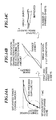
- FIGS. 18A to 18D are diagrams schematically showing charge-development characteristics of an image forming apparatus that forms images using electrophotography.
- FIG. 18A schematically shows the relationship between time elapsed after the start of the image forming apparatus and the toner charge amount.
- a developing device starts operation (rotation), and the toner charge amount rises toward a saturated charge amount.
- a difference can occur between the toner charge amount at the time of acquisition of the charge characteristics and a toner charge amount at the time of actual printing.
- the difference seriously influences image quality.
- Vl represents a light potential (potential in an exposed area), "Vcont” a developing contrast potential, “Vdev” a developing bias potential, “Vback” a fog removal potential, and "Vd” a dark potential.
- the present invention provides an image forming apparatus which is capable of making image quality more stable than in the prior art.
- an image forming apparatus as specified in claim 10.
- a method as specified in claim 11.
- a program as specified in claim 12.
- Such a program can be provided by itself or carried by a carrier medium as specified.
- the carrier medium may be a recording or other storage medium such as the storage medium specified in claim 13.
- the carrier medium may also be a transmission medium.
- the transmission medium may be a signal.
- the present invention it is possible to properly estimate the toner charge amount for actual printing based on the acquired charge-development characteristics.
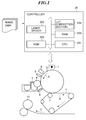
- FIG. 1 is a schematic view of an image forming apparatus according to a first embodiment of the present invention.
- FIGS. 2A and 2B are graphs showing the relationship between an image signal and image density.
- FIG. 3 is a graph showing the relationship between a reflected light amount signal and a density signal.
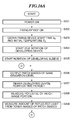
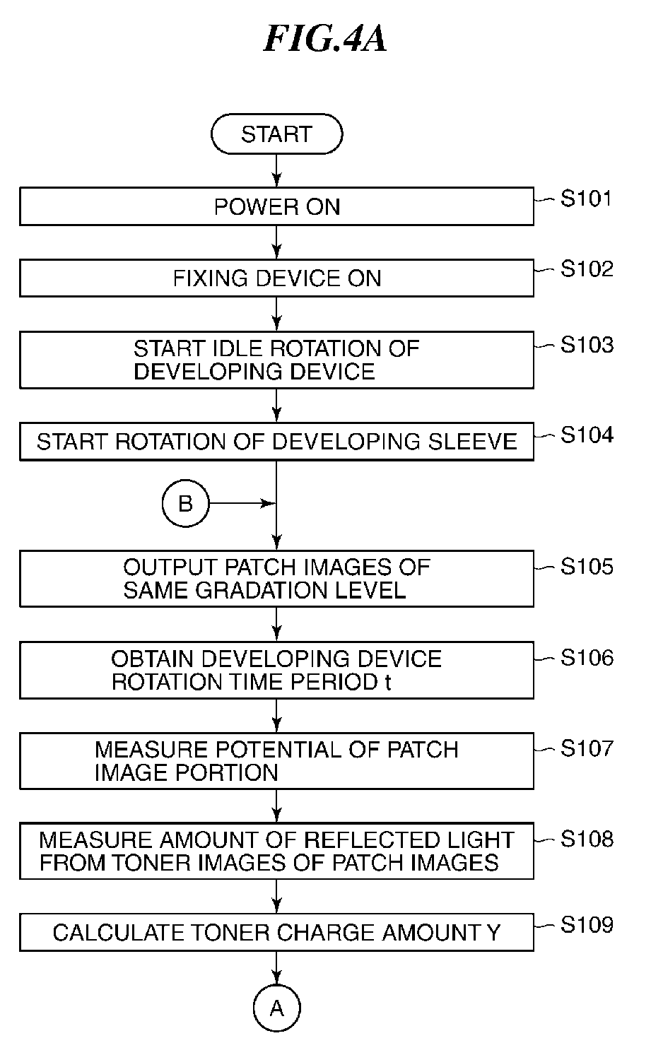
- FIGS. 4A and 4B are a flowchart of a process for acquiring rising characteristics of a toner charge amount, which is executed by the image forming apparatus according to the first embodiment.
- FIG. 5 is a schematic view useful in explaining processing executed in a step of the FIG. 4A-4B process.
- FIG. 6 is a graph showing the relationship between a reflected light amount and the toner charge amount based on data thereof prepared in advance.
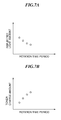
- FIGS. 7A and 7B are graphs showing, respectively, the relationship between a reflected light amount measured in the step of the FIG. 4A-4B process and a rotation time period of a developing device and the relationship between a toner charge amount calculated in another step of the FIG. 4A-4B process and the rotation time period of the developing device.
- FIG. 8 is a graph showing a general relationship between the rotation time period of the developing device and the toner charge amount.
- FIG. 9 is a graph showing the relationship between a rotation time period of the developing device and the toner charge amount, which are obtained in steps of the FIG. 4A-4B process.
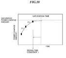
- FIG. 10 is a schematic diagram useful in explaining a process for calculating a saturated toner charge amount and a rising coefficient, using an equation representing the rate of change of the toner charge amount per unit time of the rotation time period of the developing device.
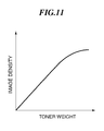
- FIG. 11 is a graph showing the relationship between a toner weight per unit area and image density.
- FIG. 12 is a diagram showing the number of printed print sheets and print density while comparing between the first embodiment and the prior art.
- FIG. 13 is a diagram showing a comparison between actual toner charge amount rising characteristics of the image forming apparatus and toner charge amount rising characteristics of the same estimated by forming patch images after the lapse of a rising time constant.
- FIGS. 14A to 14C are diagrams schematically organizing features of the first embodiment.
- FIG. 15 is a diagram schematically showing a time period for obtaining toner charge amount rising characteristics in an image forming apparatus according to a second embodiment of the present invention.
- FIGS. 16A and 16B are a flowchart of a process for acquiring the toner charge amount rising characteristics, which is executed by the image forming apparatus according to the second embodiment.
- FIG. 17 is a diagram schematically showing a gradation correction method by an image forming apparatus according to a third embodiment of the present invention.
- FIGS. 18A to 18D are diagrams schematically showing charge-development characteristics of an image forming apparatus of the related art which performs image formation using electrophotography.
- the present invention is applicable to image forming apparatuses, such as various printers and copying machines, and the component elements of an image forming apparatus of the present invention are identical to those of the conventional image forming apparatus except that the former includes units and sequences for acquisition and control of charge-development characteristics, described hereinafter, as a central component element of the present invention. Therefore, similarly to the conventional image forming apparatus, the image forming apparatus of the present invention, described in the following, is configured to scan an original image (image on an original), perform image processing, and print out image data onto a print sheet or the like. The process is also basically identical to that performed by the conventional image forming apparatus.
- FIG. 1 is a schematic view of the image forming apparatus according to a first embodiment of the present invention.
- FIG. 1 basically provides schematic illustration of component parts associated with a process of forming an electrostatic latent image on a photosensitive member as an image bearing member, then forming a toner image by attaching toner onto the electrostatic latent image, and transferring the toner image onto a print sheet or the like.
- a controller 20 The operation of the image forming apparatus is controlled by a controller 20.
- a CPU 201 loads a program stored in a ROM 202 into a RAM 203 and generates control signals by executing the program. Then, predetermined component elements of the image forming apparatus are operated and controlled according to the control signals from the controller 20, whereby a series of processes by the image forming apparatus are realized.
- a LUT correction section 204 for ⁇ -LUT correction is provided as a component element independent of the CPU 201 as shown in FIG. 1 . In the following, component elements, appearing in FIG.
- FIG. 1 An original image is read by a scanner, not shown, and a printing operation is started based on acquired image data.
- a photosensitive member (photosensitive drum) 2 as an image bearing member is driven for rotation in a direction indicated by an arrow A such that it is uniformly charged by an electrostatic charger 1.
- the photosensitive member 2 is irradiated with light by an exposure device 9 based on an image signal.
- an invisible electrostatic latent image is formed on the surface of the photosensitive member 2.
- reference numeral "5" appearing in FIG. 1 denotes a surface potential sensor.
- the surface potential sensor 5 is used to measure the surface potential of the photosensitive member 2, as described hereinafter.
- the electrostatic latent image formed on the surface of the photosensitive member 2 is developed into a visible toner image by a developing device 3.
- the developing device 3 generates the toner image e.g. by a developing method using a two-component developer formed by mixing magnetic carrier particles and non-magnetic toner particles at a predetermined ratio.
- the developer containing toner particles electrostatically charged by friction is held on a developing sleeve 8 and is conveyed to a development nip where the developing sleeve 8 and the photosensitive member 2 are close to each other.
- the toner particles conveyed to the development nip are attached onto the electrostatic latent image by a developing bias applied to the developing sleeve 8 such that the electrostatic latent image is electrostatically filled with electric charge of the toner particles.
- the electrostatic latent image is developed, whereby the toner image is generated.
- the amount of toner particles to be attached onto the electrostatic latent image i.e. a development toner amount
- the amount of developing toner increases so as to fill the electrostatic latent image, which makes the output image density (print density) higher.
- the charge amount per unit weight of the toner particles is increased, it is possible to fill the electrostatic latent image with a reduced amount of developing toner, and therefore the amount of developing toner is reduced, which makes the output image density lower.
- FIGS. 2A and 2B are graphs showing the relationship between an image signal and image density.
- multi-gradation patch images are output after the start of the image forming apparatus, and the density of each image is measured, whereby a graph ( ⁇ curve) showing the relationship between an image signal and image density is generated ("actual gradation characteristics" in FIG. 2A ).
- the ⁇ curve is inversely converted such that the ⁇ curve becomes equal to a straight line representative of a target density, whereby a gradation correction table ( ⁇ LUT) showing the relationship is generated (see FIG. 2B ).
- ⁇ LUT gradation correction table
- the ⁇ LUT is stored in a storage medium, such as a nonvolatile memory.
- image data to be printed is subjected to ⁇ conversion using the ⁇ LUT, whereby a desired output image density is obtained.
- the ⁇ LUT can become unreliable during printing e.g. due to an environmental change or a change in materials, which makes it impossible to obtain the desired output image density.
- Electrostatic latent images of respective predetermined patch images are periodically formed on the surface of the photosensitive drum 2 in a non-printing area (e.g. between print sheets), and after development, the image density of each toner image (image portion) formed on the surface of the photosensitive drum 2 is detected. Specifically, the image density is detected by measuring a reflected light amount using an optical sensor 6 (see FIG. 1 ).
- the optical sensor 6 is implemented e.g. by a reflective optical sensor configured to irradiate a toner image with infrared light at an incident angle of 45 degrees and receive light reflected at a reflection angle of 45 degrees.
- FIG. 3 is a graph showing the relationship between a reflected light amount signal and a density signal.
- the number of gradation levels is 256.
- the density signal (density value) is obtained from the graph shown in FIG. 3 , and the ⁇ LUT is corrected based on the difference between the density value and a target density.
- the FIG. 3 graph shows a general correspondence between the reflected light amount signal and the density signal. Therefore, e.g. when the relationship (dependence) between the reflected light amount signal and the density signal differs from color to color, graphs may be prepared in association with respective colors so as to obtain a density value on a color-by-color basis.
- a first ⁇ LUT is generated assuming that the toner charge amount has reached the saturated toner charge amount.
- gradations are corrected based on charge-development characteristics obtained based on the density values of patch images calculated after the start of the image forming apparatus as described in the following, whereby a desired output image density is obtained.
- FIGS. 4A and 4B are a flowchart of a process for acquiring rising characteristics of the toner charge amount, which is executed after the start of the image forming apparatus.
- step S101 When the power of the image forming apparatus is turned on (step S101), the power of the fixing device 10 is turned on (step S102), and idle rotation of the developing device 3 is started (step S103). Further, rotation of the developing sleeve 8 is started (step S104).
- the charge-development characteristics of developer can be acquired basically by grasping temporal change in the toner charge amount.
- a plurality of patch images of the same gradation level (the same image signal value) are output onto the surface of the photosensitive member 2 before a toner charge amount rising time constant ⁇ elapses after the start of the rotation of the developing device 3, whereby electrostatic latent images of the respective patch images are formed (step S105).
- a rotation time period t of the developing device 3 from the start of the idle rotation of the developing device 3 to the output of the patch images in the step S105 is obtained and stored in a memory (e.g. the RAM 203 of the controller 20) (step S106). Then, the potential of a patch image portion (i.e. an area where the electrostatic latent images of the respective patch images are formed) on the surface of the photosensitive member 2 is measured using the surface potential sensor 5 (step S107).
- a memory e.g. the RAM 203 of the controller 20
- FIG. 5 is a schematic view useful in explaining the processing executed in the step S108.
- the optical sensor 6 is implemented by a reflective optical sensor configured to irradiate a toner image with infrared light at an incident angle of 45 degrees and receive light reflected at a reflection angle of 45 degrees, as mentioned hereinbefore, but this is not limitative.
- FIG. 6 is a graph showing the relationship between the reflected light amount and the toner charge amount based on data thereof prepared in advance.
- equation (2) can be determined from FIG. 6 .
- the reflected light amount I is equal to 0.8
- it is possible to determine the toner charge amount Y as a value of -19.5 [ ⁇ C/g], using the following equation (2): Y - 15.6 / I
- FIGS. 7A and 7B are graphs respectively showing the relationship between the reflected light amount measured in the step S108 and the rotation time period of the developing device 3 and the relationship between the toner charge amount calculated in the step S109 and the rotation time period of the developing device 3.
- FIG. 8 is a graph showing a general relationship between the rotation time period t of the developing device 3 and the toner charge amount. As shown in FIG. 8 , the toner charge amount increases as the rotation time period t of the developing device 3 becomes longer, and becomes saturated at a fixed value.
- equation (3) "A” represents a saturated toner charge amount, and “p” represents the rising coefficient of the toner charge amount.
- the equation (3) contains the two unknowns "A” and “p” which cannot be determined directly in the steps 105 to S109, and therefore the steps 105 to S109 are executed while shifting the rotation time period t, so as to determine the unknowns "A” and "p".
- step S110 it is determined whether or not the toner charge amount has been calculated two or more times. If the toner charge amount has been calculated less than two times (NO to the step S110), the process returns to the step S105. If the toner charge amount has been calculated two or more times (YES to the step S110), the process proceeds to a step S111. In the step S111, simultaneous equations are solved using the rotation time period t and the toner charge amount Y determined by executing the steps 105 to S109 two or more times.
- the reciprocal of the rising coefficient p is equal to the rising time constant ⁇ of the toner charge amount, and hence in the step S111, the rising coefficient p is calculated and the rising time constant ⁇ of the toner charge amount is calculated from the following equation (7).
- FIG. 9 graph showing the relationship between the rotation time period t of the developing device 3 and the toner charge amount Y.
- the number of times of calculation of the toner charge amount is set to twice, but as the number of times of calculation is increased, the relationship between the rotation time period t and the toner charge amount Y can be determined more accurately.
- equation (3) may be replaced by the following equation (8), i.e. an equation representing the amount of change in the toner charge amount per unit time of the rotation time period of the developing device 3.
- equation (8) i.e. an equation representing the amount of change in the toner charge amount per unit time of the rotation time period of the developing device 3.
- ⁇ n ⁇ Y n - Y n + 1 / t n - t n + 1 n : natural number wherein " ⁇ " represents a correction coefficient set in advance.
- FIG. 10 is a schematic diagram useful in explaining a process for calculating the saturated toner charge amount A and the rising coefficient p using the equation (8).
- gradients ⁇ 1 and ⁇ 2 are calculated and compared with each other.
- Gradients ⁇ n and ⁇ n+1 adjacent to each other are compared while increasing the value of n, and the value of Y n+1 obtained when the ⁇ n value becomes smallest is set as the saturated toner charge amount A.
- 63% of a time period taken before the saturated toner charge amount A was reached is set as the toner charge amount rising time constant ⁇ .
- step S112 the rotation time period t of the developing device 3 obtained in the step S106 and the toner charge amount rising time constant ⁇ calculated in the step S111 are compared with each other, whereby it is determined whether or not the relationship of "t > ⁇ " is satisfied (step S112).
- step S112 If the relationship of "t > ⁇ " is not satisfied (NO to the step S112), which means that the time period for calculating a toner charge amount rising coefficient p and a saturated toner charge amount A and generating a ⁇ LUT is over, the present process is terminated, and the ⁇ LUT, the toner charge amount rising coefficient p, and the saturated toner charge amount A stored in the memory are used for execution of an image printing sequence. If the relationship of "t > ⁇ " is satisfied (YES to the step S112), the process proceeds to a step S113. In the step S113, the toner charge amount rising coefficient p and the saturated toner charge amount A calculated in the step S111 are stored in a memory (e.g.
- the rising prediction equation generated as above is used before execution of the image printing sequence (i.e. before printing an image on a print sheet) so as to predict a change in the toner charge amount.
- an image density is calculated from the per-unit area toner weight obtained in the step S114, using the relationship, shown in FIG. 11 , between per-unit area toner weight and image density (step S115). Then, a new ⁇ LUT is generated by correcting the ⁇ LUT stored in advance in the memory, using the image density calculated in the step S115, and is then stored in the memory (step S116).
- the toner charge amount Y is predicted using the toner charge amount rising coefficient p and the saturated toner charge amount A, calculated as described above, and a ⁇ LUT is generated for each print sheet or the like by executing the steps S114 to S116, whereby printing is performed on the print sheet or the like.
- the charge characteristics and development characteristics of developer are acquired during a time period before the other conditions change and a time period during which the charge characteristics and the development characteristics are reflected, so that it is possible to control output image density properly, starting from printing on a first print sheet.
- FIG. 12 is a diagram showing the number of printed print sheets and print density while comparing between the first embodiment and the prior art.
- the density of an actually printed image sharply changes as shown in FIG. 12 . The reason for this will be explained with reference to FIG. 13 .
- FIG. 13 is a diagram showing a comparison between actual toner charge amount rising characteristics of the image forming apparatus and toner charge amount rising characteristics of the same estimated in the prior art by forming patch images after the lapse of the rising time constant ⁇ .
- the method of the prior art is used to estimate the toner charge amount, it is impossible to calculate the rising coefficient accurately. For this reason, the difference from the actual rising characteristics (actual measured value) appears as a large rising estimation curve (broken line), and the saturated toner charge amount also largely deviates from the actual measured value.
- the error between the toner charge amount obtained immediately after the start of the image forming apparatus and the actual toner charge amount is large, and image forming conditions are set using a value with such a large error, so that the output image density largely deviates from a target density.
- image forming conditions are set using a value with such a large error, so that the output image density largely deviates from a target density.
- FIGS. 14A to 14C are diagrams schematically organizing features of the present embodiment.
- the steps S105 to S116 are executed before the lapse of the toner charge amount rising time constant ⁇ . This makes it possible to properly estimate values of the toner charge amount rising characteristics and the saturated toner charge amount as will be obtained after the lapse of the rising time constant ⁇ . In other words, it is possible to properly predict the toner charge amount in a state in which the estimated toner charge amount rising characteristics substantially match actually measured toner charge amount rising characteristics.
- the toner charge amount can be properly estimated, so that even when the toner charge amount has not reached the saturated toner charge amount during a time period from the start of the image forming apparatus to actual image printing, it is possible to properly set image forming conditions while taking into account a change in the toner charge amount, from the start of printing on a first print sheet.
- the saturated toner charge amount can be properly estimated based on the rising characteristics of the toner charge amount, before actual printing, it is possible to reduce time (idle rotation time of the developing device 3) required to saturate the toner charge amount, to thereby improve processing performance for printing on print sheets.
- the image forming apparatus has the same hardware configuration as that in the first embodiment, and therefore detailed description thereof is omitted.
- the toner charge amount rising time constant ⁇ and the saturated toner charge amount A sometimes change e.g. due to an environmental change.
- an environmental change such as a rise in ambient temperature of the fixing device 10
- FIG. 15 is a diagram schematically showing the time period for determining the toner charge amount rising characteristics in the second embodiment.
- FIGS. 16A and 16B are a flowchart of a process for determining the toner charge amount rising characteristics, which executed by the image forming apparatus according to the second embodiment. Further, steps in FIGS. 16A and 16B identical to those described with reference to FIGS. 4A and 4B in the first embodiment will be described just briefly, and detailed description thereof is omitted.
- step S201 When the power of the image forming apparatus is turned on (step S201), the power of the fixing device 10 is automatically turned on (step S202). Then, a start time tt 0 when the power of the fixing device 10 was turned on and an initial temperature To of the fixing device 10 at the start time tt 0 are obtained and stored in the memory (step S203).
- step S204 when idle rotation of the developing device 3 is started (step S204) and rotation of the developing sleeve 8 is started (step S205), a plurality of patch images of the same gradation level (the same image signal value) are output onto the surface of the photosensitive member 2, whereby electrostatic latent images are formed (step S206). Then, a rotation time period t of the developing device 3 from the start of the idle rotation of the developing device 3 to the output of the patch images in the step S206 is obtained and stored in the memory (step S207). Then, the potential of the patch image portion on the surface of the photosensitive member 2 is measured using the surface potential sensor 5 (step S208). Further, the electrostatic latent images are developed into toner images, and the amount of reflected light from the toner images of the patch images formed on the surface of the photosensitive member 2 is measured using the optical sensor 6 (step S209).
- a toner charge amount Y is calculated using the potential V measured in the step S208 and a density value D converted from the reflected light amount obtained in the step S209 (step S210).
- it is determined whether or not the toner charge amount has been calculated two or more times step S211. If the toner charge amount has been calculated less than two times (NO to the step S211), the process returns to the step S206. If the toner charge amount has been calculated two or more times (YES to the step S211), the process proceeds to a step S212.
- a saturated toner charge amount A and a toner charge amount rising coefficient p are calculated based on the rotation time period t and the toner charge amount Y determined by executing the steps S206 to S210, and a toner charge amount rising time constant ⁇ is calculated using the saturated toner charge amount A and toner charge amount rising coefficient p thus calculated.
- step S213 the rotation time period t of the developing device 3 obtained in the step S207 and the toner charge amount rising time constant ⁇ calculated in the step S212 are compared with each other, whereby it is determined whether or not the relationship of "t > ⁇ " is satisfied (step S213). If the relationship of "t > ⁇ " is not satisfied (NO to the step S213), the present process is terminated, and the toner charge amount rising time constant ⁇ and the saturated toner charge amount A stored in the memory are used. If the relationship of "t > ⁇ " is satisfied (YES to the step S213), the process proceeds to a step S214, wherein a rising prediction equation for predicting the toner charge amount Y at the time of start-up is formed. Note that the steps S201, S202, and S204 to S214 correspond to the respective steps S101, S102, and S103 to S113 described with reference to FIGS. 4A and 4B .
- a current time tt i and a current temperature T i of the fixing device 10 are obtained (step S215).
- the values obtained in the step S215 and the start time tt 0 and the temperature To of the fixing device 10 stored in the memory are used to calculate a temperature change rate dTe with respect to time.
- a conversion table for use in calculating the internal temperature of the developing device 3 with respect to rise in the temperature of the fixing device 10 has been formed in advance by preparing an environment table and measuring the internal temperature of the developing device 3 e.g. through experiment, and is stored in a memory (e.g. the ROM 202 of the controller 20).
- the temperature change rate dTe may be calculated based on data which was obtained in advance by measuring the change characteristics of the internal temperature of the developing device 3 e.g. through experiment after the turn-on of the developing device 3, and is stored in a memory (e.g. the ROM 202 of the controller 20) in a tabulated form.
- a temperature and humidity sensor or the like may be provided in the developing device 3 for directly measuring the temperature change rate dTe, and a value thus obtained by the measurement may be used.
- a step S216 it is further determined whether or not the obtained temperature change rate dTe is in the relationship of "dTe ⁇ 5.0". If “dTe ⁇ 5.0" holds (YES to the step S216), the toner charge amount rising time constant ⁇ and the saturated toner charge amount A calculated in the step S212 are stored in the memory (step S217), followed by terminating the present process. On the other hand, if “dTe ⁇ 5.0" holds (NO to the step S216), the present process is terminated, so that the toner charge amount rising time constant ⁇ and the saturated toner charge amount A stored in the memory are used.
- the toner charge amount rising characteristics are estimated immediately after the start of the image forming apparatus, in the stable environment before the internal temperature of the developing device 3 rises due to the start of the fixing device 10. This makes it possible to calculate the toner charge amount rising time constant ⁇ and the saturated toner charge amount A with high accuracy.
- the image forming apparatus has the same hardware configuration as that in the first embodiment, and therefore detailed description thereof is omitted.
- gradation correction is performed using the ⁇ LUT.
- gradation correction is performed by correcting the laser intensity of the exposure device 9 that performs exposure on the photosensitive member 2.
- the toner charge amount is predicted, and a setting of the laser intensity of the exposure device 9 is corrected according to the predicted toner charge amount.
- a toner charge amount Y i before the start of printing is predicted by a toner charge amount rising prediction equation using the toner charge amount rising coefficient p and the saturated toner charge amount A calculated following the steps S101 to S111 in the first embodiment.
- the CPU 201 of the controller 20 multiplies the input signal by the correction coefficient q and delivers the resulting input signal to a laser driver 205 for driving the exposure device 9.
- the potential of an electrostatic latent image formed on the surface of the photosensitive member 2 is changed such that the electrostatic latent image can be developed by an appropriate amount of toner, which makes it possible to stably control output image density.
- FIG. 17 is a diagram schematically showing the above-described gradation correction method employed in the third embodiment. Note that potentials, such as Vdev, appearing on the vertical axis in FIG. 17 , are the same as those appearing in FIGS. 18A to 18D .
- FIG. 17 illustrates an exemplary case in which when the toner charge amount is high, the potential of an exposed area is lowered to increase the amount of toner required for development so as to prevent reduction of output image density from being caused by development of an electrostatic latent image by a reduced amount of toner particles, whereby a toner amount is ensured which enables a target density to be obtained.
- the present invention is not limited to the above-described embodiments.
- the image forming apparatus may be different in construction from the above-described image forming apparatus.
- aspects of the present invention can also be realized by a computer of a system or apparatus (or devices such as a CPU or MPU) that reads out and executes a program recorded on a memory device to perform the functions of the above-described embodiments, and by a method, the steps of which are performed by a computer of a system or apparatus by, for example, reading out and executing a program recorded on a memory device to perform the functions of the above-described embodiments.
- the program is provided to the computer for example via a network or from a recording medium of various types serving as the memory device (e.g., computer-readable medium).
Landscapes
- Engineering & Computer Science (AREA)
- Microelectronics & Electronic Packaging (AREA)
- Physics & Mathematics (AREA)
- General Physics & Mathematics (AREA)
- Control Or Security For Electrophotography (AREA)
- Dry Development In Electrophotography (AREA)
Abstract
An image forming apparatus capable of making image quality more stable than in the prior art. An electrostatic latent image is formed on the surface of a photosensitive member based on an image signal. A developing device develops the electrostatic latent image on the photosensitive member by toner to thereby form a patch image (S105). An optical sensor detects the density of the patch image (S107). A toner charge amount is calculated from the density detected by the optical sensor, and a change in the toner charge amount is predicted (S109) based on a plurality of results of the calculation of the toner charge amount (S110). The image forming apparatus generates a γLUT (S116) for use in correcting the relationship between the image signal and the density based on the predicted change in the toner charge amount.
Description
- The present invention relates to an image forming apparatus using electrophotography.
- Roughly, image formation using electrophotography is performed through the following process: First, a photosensitive member as an image bearing member is charged by an electrostatic charger, and an invisible electrostatic latent image is formed on the surface of the charged photosensitive member by being irradiated with light by an exposure device, whereafter a toner image is generated by visualizing the invisible electrostatic latent image using colored toner particles as a developer. The so-called developing process for generating the toner image is realized by moving and placing the charged toner particles by electrostatic forces. Then, the toner image formed on the surface of the photosensitive member is transferred onto a print sheet by electrostatic forces directly or via a transfer member and is finally fixed on the print sheet by a fixing device.
- In an apparatus configured to form an image by electrostatically attaching toner onto a photosensitive member, a change in the amount of charged toner (hereinafter referred to as "the toner charge amount") directly leads to changes in color hue and density. For example, the toner charge amount changes with time according to an amount of printing of characters and images, a toner replenishment rate, an environment, and so forth, and hence even in a case where the same image is continuously printed, color hue and density can differ between a first copy and a final one. To cope with this problem, it is important to accurately grasp a change in the toner charge amount, i.e. charge-development characteristics.
- To improve stability of image quality (i.e. the quality of printing on print sheets or the like), there has been proposed a technique in which a predetermined gradation patch is formed before or after image formation or during image formation and a deviation of a formed gradation patch from a proper one to be formed is corrected. For example, after completion of warm-up of an image forming apparatus, a predetermined image pattern is formed on an image bearing member, and the density of the image pattern is detected. Then, the configuration of a circuit, such as a gamma correction circuit, for changing image forming conditions is changed to improve the stability of image quality (see e.g. Japanese Patent Laid-Open Publication No.
H04-343573 - However, the conventional technique for improving the stability of image quality suffers from various problems. The problems will be described with reference to
FIGS. 18A to 18D. FIGS. 18A to 18D are diagrams schematically showing charge-development characteristics of an image forming apparatus that forms images using electrophotography. -
FIG. 18A schematically shows the relationship between time elapsed after the start of the image forming apparatus and the toner charge amount. When the image forming apparatus is started, a developing device starts operation (rotation), and the toner charge amount rises toward a saturated charge amount. Depending on timing in which charge characteristics (toner charge amount) are acquired during the rise in the toner charge amount, a difference (deviation) can occur between the toner charge amount at the time of acquisition of the charge characteristics and a toner charge amount at the time of actual printing. The difference (deviation) seriously influences image quality. - More specifically, as schematically illustrated in
FIG. 18B , when a toner charge amount set for actual printing is high, the amount of toner particles attached onto an electrostatic latent image formed based on the obtained charge characteristics is reduced, which makes output image density (print density) low. On the other hand, when the actual toner charge amount is low, the amount of toner particles attached onto an electrostatic latent image formed based on the obtained charge characteristics is increased, which makes the output image density high. Note that a vertical axis inFIG. 18B represents the surface potential of a photosensitive member, and "Vl" represents a light potential (potential in an exposed area), "Vcont" a developing contrast potential, "Vdev" a developing bias potential, "Vback" a fog removal potential, and "Vd" a dark potential. - As shown in
FIG. 18C , when image forming conditions are set in a state where a difference (deviation) in toner charge amount is not corrected, control deviating from optimal gradation characteristics is performed, so that a density change from a target density is increased, which causes serious degradation of control stability. As a consequence, the difference between the target density and the output image density is increased with an increase in the number of print sheets as shown inFIG. 18D , which makes color very unstable. - The present invention provides an image forming apparatus which is capable of making image quality more stable than in the prior art.
- In a first aspect of the present invention, there is provided an image forming apparatus as specified in
claims 1 to 8. In a second aspect of the present invention, there is provided a method as specified inclaim 9. - In a third aspect of the present invention, there is provided an image forming apparatus as specified in
claim 10. In a fourth aspect of the present invention, there is provided a method as specified in claim 11. In a fifth aspect of the present invention, there is provided a program as specified in claim 12. Such a program can be provided by itself or carried by a carrier medium as specified. The carrier medium may be a recording or other storage medium such as the storage medium specified in claim 13. The carrier medium may also be a transmission medium. The transmission medium may be a signal. - According to the present invention, it is possible to properly estimate the toner charge amount for actual printing based on the acquired charge-development characteristics.
- Further features of the present invention will become apparent from the following description of exemplary embodiments with reference to the attached drawings.
-
FIG. 1 is a schematic view of an image forming apparatus according to a first embodiment of the present invention. -
FIGS. 2A and 2B are graphs showing the relationship between an image signal and image density. -
FIG. 3 is a graph showing the relationship between a reflected light amount signal and a density signal. -
FIGS. 4A and4B are a flowchart of a process for acquiring rising characteristics of a toner charge amount, which is executed by the image forming apparatus according to the first embodiment. -
FIG. 5 is a schematic view useful in explaining processing executed in a step of theFIG. 4A-4B process. -
FIG. 6 is a graph showing the relationship between a reflected light amount and the toner charge amount based on data thereof prepared in advance. -
FIGS. 7A and 7B are graphs showing, respectively, the relationship between a reflected light amount measured in the step of theFIG. 4A-4B process and a rotation time period of a developing device and the relationship between a toner charge amount calculated in another step of theFIG. 4A-4B process and the rotation time period of the developing device. -
FIG. 8 is a graph showing a general relationship between the rotation time period of the developing device and the toner charge amount. -
FIG. 9 is a graph showing the relationship between a rotation time period of the developing device and the toner charge amount, which are obtained in steps of theFIG. 4A-4B process. -
FIG. 10 is a schematic diagram useful in explaining a process for calculating a saturated toner charge amount and a rising coefficient, using an equation representing the rate of change of the toner charge amount per unit time of the rotation time period of the developing device. -
FIG. 11 is a graph showing the relationship between a toner weight per unit area and image density. -
FIG. 12 is a diagram showing the number of printed print sheets and print density while comparing between the first embodiment and the prior art. -
FIG. 13 is a diagram showing a comparison between actual toner charge amount rising characteristics of the image forming apparatus and toner charge amount rising characteristics of the same estimated by forming patch images after the lapse of a rising time constant. -
FIGS. 14A to 14C are diagrams schematically organizing features of the first embodiment. -
FIG. 15 is a diagram schematically showing a time period for obtaining toner charge amount rising characteristics in an image forming apparatus according to a second embodiment of the present invention. -
FIGS. 16A and16B are a flowchart of a process for acquiring the toner charge amount rising characteristics, which is executed by the image forming apparatus according to the second embodiment. -
FIG. 17 is a diagram schematically showing a gradation correction method by an image forming apparatus according to a third embodiment of the present invention. -
FIGS. 18A to 18D are diagrams schematically showing charge-development characteristics of an image forming apparatus of the related art which performs image formation using electrophotography. - The present invention will now be described in detail below with reference to the accompanying drawings showing embodiments thereof. Specifically, the present invention is applicable to image forming apparatuses, such as various printers and copying machines, and the component elements of an image forming apparatus of the present invention are identical to those of the conventional image forming apparatus except that the former includes units and sequences for acquisition and control of charge-development characteristics, described hereinafter, as a central component element of the present invention. Therefore, similarly to the conventional image forming apparatus, the image forming apparatus of the present invention, described in the following, is configured to scan an original image (image on an original), perform image processing, and print out image data onto a print sheet or the like. The process is also basically identical to that performed by the conventional image forming apparatus.
-
FIG. 1 is a schematic view of the image forming apparatus according to a first embodiment of the present invention.FIG. 1 basically provides schematic illustration of component parts associated with a process of forming an electrostatic latent image on a photosensitive member as an image bearing member, then forming a toner image by attaching toner onto the electrostatic latent image, and transferring the toner image onto a print sheet or the like. - The operation of the image forming apparatus is controlled by a
controller 20. In thecontroller 20, aCPU 201 loads a program stored in aROM 202 into aRAM 203 and generates control signals by executing the program. Then, predetermined component elements of the image forming apparatus are operated and controlled according to the control signals from thecontroller 20, whereby a series of processes by the image forming apparatus are realized. Note that in the present embodiment, aLUT correction section 204 for γ-LUT correction, described hereinafter, is provided as a component element independent of theCPU 201 as shown inFIG. 1 . In the following, component elements, appearing inFIG. 1 , of the image forming apparatus will be described according to steps (a latent image forming step, a developing step (toner image forming step), a transfer step and fixing step, and a gradation correction step) of an image forming process executed by the image forming apparatus. - [Latent Image Forming Step] In the image forming apparatus, an original image is read by a scanner, not shown, and a printing operation is started based on acquired image data. A photosensitive member (photosensitive drum) 2 as an image bearing member is driven for rotation in a direction indicated by an arrow A such that it is uniformly charged by an
electrostatic charger 1. Then, thephotosensitive member 2 is irradiated with light by anexposure device 9 based on an image signal. As a consequence, an invisible electrostatic latent image is formed on the surface of thephotosensitive member 2. Note that reference numeral "5" appearing inFIG. 1 denotes a surface potential sensor. The surfacepotential sensor 5 is used to measure the surface potential of thephotosensitive member 2, as described hereinafter. - [Developing Step (Toner Image Forming Step)] The electrostatic latent image formed on the surface of the
photosensitive member 2 is developed into a visible toner image by a developingdevice 3. The developingdevice 3 generates the toner image e.g. by a developing method using a two-component developer formed by mixing magnetic carrier particles and non-magnetic toner particles at a predetermined ratio. The developer containing toner particles electrostatically charged by friction is held on a developingsleeve 8 and is conveyed to a development nip where the developingsleeve 8 and thephotosensitive member 2 are close to each other. - The toner particles conveyed to the development nip are attached onto the electrostatic latent image by a developing bias applied to the developing
sleeve 8 such that the electrostatic latent image is electrostatically filled with electric charge of the toner particles. Thus, the electrostatic latent image is developed, whereby the toner image is generated. The amount of toner particles to be attached onto the electrostatic latent image (i.e. a development toner amount) depends on a charge amount per unit weight of toner particles, and therefore when a change occurs in the charge amount of toner particles e.g. due to change in temperature and humidity or aging change in material characteristics, the development toner amount changes. Specifically, as the charge amount per unit weight of the toner particles is reduced, the amount of developing toner increases so as to fill the electrostatic latent image, which makes the output image density (print density) higher. On the other hand, when the charge amount per unit weight of the toner particles is increased, it is possible to fill the electrostatic latent image with a reduced amount of developing toner, and therefore the amount of developing toner is reduced, which makes the output image density lower. - [Transfer Step and Fixing Step] When a transfer voltage is applied to a
transfer roller 7 opposed to thephotosensitive member 2 via anintermediate transfer belt 4, the toner image formed on thephotosensitive member 2 is transferred from the surface of thephotosensitive member 2 onto the surface of theintermediate transfer belt 4 by electrostatic forces. The toner image transferred onto the surface of theintermediate transfer belt 4 is conveyed in a direction of rotation of theintermediate transfer belt 4, i.e. a direction indicated by an arrow B, and is transferred onto a medium, such as a print sheet, conveyed in a direction indicated by an arrow C. The print sheet or the like having the toner image transferred thereon is conveyed to a fixingdevice 10, where the toner image is fixed on the print sheet or the like by heat and pressure. - [Gradation Correction Step]
FIGS. 2A and 2B are graphs showing the relationship between an image signal and image density. In general, multi-gradation patch images are output after the start of the image forming apparatus, and the density of each image is measured, whereby a graph (γ curve) showing the relationship between an image signal and image density is generated ("actual gradation characteristics" inFIG. 2A ). Then, the γ curve is inversely converted such that the γ curve becomes equal to a straight line representative of a target density, whereby a gradation correction table (γLUT) showing the relationship is generated (seeFIG. 2B ). Note that the γLUT is stored in a storage medium, such as a nonvolatile memory. - After generation of the γLUT, image data to be printed is subjected to γ conversion using the γLUT, whereby a desired output image density is obtained. However, the γLUT can become unreliable during printing e.g. due to an environmental change or a change in materials, which makes it impossible to obtain the desired output image density.
- To avoid this, control for correcting the yLUT is performed as control for correcting gradation. Electrostatic latent images of respective predetermined patch images are periodically formed on the surface of the
photosensitive drum 2 in a non-printing area (e.g. between print sheets), and after development, the image density of each toner image (image portion) formed on the surface of thephotosensitive drum 2 is detected. Specifically, the image density is detected by measuring a reflected light amount using an optical sensor 6 (seeFIG. 1 ). Theoptical sensor 6 is implemented e.g. by a reflective optical sensor configured to irradiate a toner image with infrared light at an incident angle of 45 degrees and receive light reflected at a reflection angle of 45 degrees. -
FIG. 3 is a graph showing the relationship between a reflected light amount signal and a density signal. In the present graph, the number of gradation levels is 256. The density signal (density value) is obtained from the graph shown inFIG. 3 , and the γLUT is corrected based on the difference between the density value and a target density. Note that theFIG. 3 graph shows a general correspondence between the reflected light amount signal and the density signal. Therefore, e.g. when the relationship (dependence) between the reflected light amount signal and the density signal differs from color to color, graphs may be prepared in association with respective colors so as to obtain a density value on a color-by-color basis. - In the conventional image forming apparatus, a first γLUT is generated assuming that the toner charge amount has reached the saturated toner charge amount. However, if the toner charge amount has not actually reached the saturated toner charge amount and the toner charge amount increases during printing, deviation from a desired output image density occurs. To solve this problem, in the image forming apparatus according to the present invention, gradations are corrected based on charge-development characteristics obtained based on the density values of patch images calculated after the start of the image forming apparatus as described in the following, whereby a desired output image density is obtained.
-
FIGS. 4A and4B are a flowchart of a process for acquiring rising characteristics of the toner charge amount, which is executed after the start of the image forming apparatus. When the power of the image forming apparatus is turned on (step S101), the power of the fixingdevice 10 is turned on (step S102), and idle rotation of the developingdevice 3 is started (step S103). Further, rotation of the developingsleeve 8 is started (step S104). - The charge-development characteristics of developer can be acquired basically by grasping temporal change in the toner charge amount. For the purpose of grasping the temporal change in the toner charge amount, first, a plurality of patch images of the same gradation level (the same image signal value) are output onto the surface of the
photosensitive member 2 before a toner charge amount rising time constant τ elapses after the start of the rotation of the developingdevice 3, whereby electrostatic latent images of the respective patch images are formed (step S105). - A rotation time period t of the developing
device 3 from the start of the idle rotation of the developingdevice 3 to the output of the patch images in the step S105 is obtained and stored in a memory (e.g. theRAM 203 of the controller 20) (step S106). Then, the potential of a patch image portion (i.e. an area where the electrostatic latent images of the respective patch images are formed) on the surface of thephotosensitive member 2 is measured using the surface potential sensor 5 (step S107). - Then, the electrostatic latent images are developed into toner images, and the amount of reflected light from the toner images of the patch images formed on the surface of the photosensitive member 2 (from the area where toner images of the patch images are formed) is measured using the optical sensor 6 (step S108).
FIG. 5 is a schematic view useful in explaining the processing executed in the step S108. In the present embodiment, theoptical sensor 6 is implemented by a reflective optical sensor configured to irradiate a toner image with infrared light at an incident angle of 45 degrees and receive light reflected at a reflection angle of 45 degrees, as mentioned hereinbefore, but this is not limitative. - A toner charge amount Y is calculated using a potential V measured in the step S107 and a density value D converted from a reflected light amount measured in the step S108 (step S109) by the following equation (1):

wherein "a" represents a coefficient determined by a toner type, characteristics of the developingdevice 3, etc. - Note that data indicative of the relationship between the reflected light amount and the toner charge amount may be provided in advance and the toner charge amount may be calculated from the reflected light amount measured in the step S108 by using the data.
FIG. 6 is a graph showing the relationship between the reflected light amount and the toner charge amount based on data thereof prepared in advance. For example, the following equation (2) can be determined fromFIG. 6 . When the reflected light amount I is equal to 0.8, it is possible to determine the toner charge amount Y as a value of -19.5 [µ C/g], using the following equation (2):
- By executing the steps S105 to S107 and steps S108 and S109 while shifting the rotation time period t of the developing
device 3, it is possible to obtain actual measurement data indicative of changes in the toner charge amount with respect to the rotation time period of the developingdevice 3 after the start of the image forming apparatus, as illustrated inFIGS. 7A and 7B. FIGS. 7A and 7B are graphs respectively showing the relationship between the reflected light amount measured in the step S108 and the rotation time period of the developingdevice 3 and the relationship between the toner charge amount calculated in the step S109 and the rotation time period of the developingdevice 3. - Incidentally, the toner charge amount increases as toner is charged by triboelectrifica-tion between toner particles and carrier particles. Therefore, if the developing
device 3 is rotated without replenishment or consumption of the toner particles, the toner charge amount becomes large.FIG. 8 is a graph showing a general relationship between the rotation time period t of the developingdevice 3 and the toner charge amount. As shown inFIG. 8 , the toner charge amount increases as the rotation time period t of the developingdevice 3 becomes longer, and becomes saturated at a fixed value. The curve of the toner charge amount Y at this time can generally be expressed by the following equation (3):
- In the equation (3), "A" represents a saturated toner charge amount, and "p" represents the rising coefficient of the toner charge amount. The equation (3) contains the two unknowns "A" and "p" which cannot be determined directly in the
steps 105 to S109, and therefore thesteps 105 to S109 are executed while shifting the rotation time period t, so as to determine the unknowns "A" and "p". - Then, it is determined whether or not the toner charge amount has been calculated two or more times (step S110). If the toner charge amount has been calculated less than two times (NO to the step S110), the process returns to the step S105. If the toner charge amount has been calculated two or more times (YES to the step S110), the process proceeds to a step S111. In the step S111, simultaneous equations are solved using the rotation time period t and the toner charge amount Y determined by executing the
steps 105 to S109 two or more times. - More specifically, the toner charge amount Y1 corresponding to the rotation time period t1 and the toner charge amount Y2 corresponding to the rotation time period t2 are obtained, and the obtained two values are substituted into the equation (3). Thus, simultaneous equations (4) are obtained, and the values "A" and "p" are calculated from the simultaneous equations (4), from the equations (5) and (6) (step S111) :


- The reciprocal of the rising coefficient p is equal to the rising time constant τ of the toner charge amount, and hence in the step S111, the rising coefficient p is calculated and the rising time constant τ of the toner charge amount is calculated from the following equation (7). The rising time constant τ of the toner charge amount represents a time period required for the toner charge amount to reach approximately 63% of the saturated toner charge amount.

- By executing the steps S105 to S111, it is possible to obtain a
FIG. 9 graph showing the relationship between the rotation time period t of the developingdevice 3 and the toner charge amount Y. In the present embodiment, the number of times of calculation of the toner charge amount is set to twice, but as the number of times of calculation is increased, the relationship between the rotation time period t and the toner charge amount Y can be determined more accurately. - Note that the equation (3) may be replaced by the following equation (8), i.e. an equation representing the amount of change in the toner charge amount per unit time of the rotation time period of the developing
device 3.
wherein "α" represents a correction coefficient set in advance. -
FIG. 10 is a schematic diagram useful in explaining a process for calculating the saturated toner charge amount A and the rising coefficient p using the equation (8). For example, first, gradients β1 and β2 are calculated and compared with each other. Gradients βn and βn+1 adjacent to each other are compared while increasing the value of n, and the value of Yn+1 obtained when the βn value becomes smallest is set as the saturated toner charge amount A. Then, 63% of a time period taken before the saturated toner charge amount A was reached is set as the toner charge amount rising time constant τ. - Next, the rotation time period t of the developing
device 3 obtained in the step S106 and the toner charge amount rising time constant τ calculated in the step S111 are compared with each other, whereby it is determined whether or not the relationship of "t > τ" is satisfied (step S112). - If the relationship of "t > τ" is not satisfied (NO to the step S112), which means that the time period for calculating a toner charge amount rising coefficient p and a saturated toner charge amount A and generating a γLUT is over, the present process is terminated, and the γLUT, the toner charge amount rising coefficient p, and the saturated toner charge amount A stored in the memory are used for execution of an image printing sequence. If the relationship of "t > τ" is satisfied (YES to the step S112), the process proceeds to a step S113. In the step S113, the toner charge amount rising coefficient p and the saturated toner charge amount A calculated in the step S111 are stored in a memory (e.g. the memory storing the γLUT) and are applied to the equation (3), whereby a rising prediction equation for predicting the toner charge amount Y at the time of start-up is formed. The rising prediction equation generated as above is used before execution of the image printing sequence (i.e. before printing an image on a print sheet) so as to predict a change in the toner charge amount.
- Then, the toner charge amount Y is estimated using the rising prediction equation formed in the step S113, and a toner weight M per unit area is calculated from the relationship between the toner charge amount and the toner weight M per unit area, which is represented by the following equation (9)(step S114) :

wherein "k" represents a proportionality constant indicative of the relationship between the toner charge amount and the toner weight. - Further, an image density is calculated from the per-unit area toner weight obtained in the step S114, using the relationship, shown in
FIG. 11 , between per-unit area toner weight and image density (step S115). Then, a new γLUT is generated by correcting the γLUT stored in advance in the memory, using the image density calculated in the step S115, and is then stored in the memory (step S116). - During execution of the image printing sequence, the toner charge amount Y is predicted using the toner charge amount rising coefficient p and the saturated toner charge amount A, calculated as described above, and a γLUT is generated for each print sheet or the like by executing the steps S114 to S116, whereby printing is performed on the print sheet or the like. As described above, according to the present embodiment, the charge characteristics and development characteristics of developer are acquired during a time period before the other conditions change and a time period during which the charge characteristics and the development characteristics are reflected, so that it is possible to control output image density properly, starting from printing on a first print sheet.
-
FIG. 12 is a diagram showing the number of printed print sheets and print density while comparing between the first embodiment and the prior art. In the prior art, the density of an actually printed image sharply changes as shown inFIG. 12 . The reason for this will be explained with reference toFIG. 13 . -
FIG. 13 is a diagram showing a comparison between actual toner charge amount rising characteristics of the image forming apparatus and toner charge amount rising characteristics of the same estimated in the prior art by forming patch images after the lapse of the rising time constant τ. When the method of the prior art is used to estimate the toner charge amount, it is impossible to calculate the rising coefficient accurately. For this reason, the difference from the actual rising characteristics (actual measured value) appears as a large rising estimation curve (broken line), and the saturated toner charge amount also largely deviates from the actual measured value. - As described above, in the prior art, the error between the toner charge amount obtained immediately after the start of the image forming apparatus and the actual toner charge amount is large, and image forming conditions are set using a value with such a large error, so that the output image density largely deviates from a target density. In other words, in a case where patch images are formed after the lapse of the rising time constant τ so as to estimate the toner charge amount rising coefficient p and the saturated toner charge amount A included in the charge-development characteristics, a change in the toner charge amount (i.e. the rising characteristics) cannot be estimated accurately.
- In contrast, it is understood that in the present embodiment, density deviation from the target density is reduced from the start of printing on a first print sheet, as shown in
FIG. 12 .FIGS. 14A to 14C are diagrams schematically organizing features of the present embodiment. As described hereinbefore, in the present embodiment, after the start of rotation of the developingdevice 3, the steps S105 to S116 are executed before the lapse of the toner charge amount rising time constant τ. This makes it possible to properly estimate values of the toner charge amount rising characteristics and the saturated toner charge amount as will be obtained after the lapse of the rising time constant τ. In other words, it is possible to properly predict the toner charge amount in a state in which the estimated toner charge amount rising characteristics substantially match actually measured toner charge amount rising characteristics. Thus, the toner charge amount can be properly estimated, so that even when the toner charge amount has not reached the saturated toner charge amount during a time period from the start of the image forming apparatus to actual image printing, it is possible to properly set image forming conditions while taking into account a change in the toner charge amount, from the start of printing on a first print sheet. - According to the present embodiment, since optimal image forming conditions can be set on a print sheet-by-print sheet basis as shown in
FIG. 14B , color stability is greatly improved, which makes it possible to stably print a high-image quality image as shown inFIGS. 12 and14C . Further, according to the present embodiment, since the saturated toner charge amount can be properly estimated based on the rising characteristics of the toner charge amount, before actual printing, it is possible to reduce time (idle rotation time of the developing device 3) required to saturate the toner charge amount, to thereby improve processing performance for printing on print sheets. - Next, an image forming apparatus according to a second embodiment of the present invention will be described. In the present embodiment, the image forming apparatus has the same hardware configuration as that in the first embodiment, and therefore detailed description thereof is omitted.
- In the first embodiment, after the image forming apparatus is started and rotation of the developing
sleeve 8 is started, a plurality of patch images of the gradation are formed before the lapse of the toner charge amount rising time constant τ, and the toner charge amount rising characteristics are determined within a time period reflecting the charge characteristics of developer. However, the toner charge amount rising time constant τ and the saturated toner charge amount A sometimes change e.g. due to an environmental change. For example, when the image forming apparatus is started and the fixingdevice 10 starts operation, an environmental change, such as a rise in ambient temperature of the fixingdevice 10, can occur to have influence on the toner charge amount rising characteristics. When environment within the developingdevice 3 changes during measurement of the toner charge amount rising characteristics, it is impossible to accurately determine the rising characteristics of the toner charge amount due to the influence of the environmental change. - To solve this problem, in the second embodiment of the present invention, after the start of the image forming apparatus, the toner charge amount rising characteristics are determined within a time period, during which the environment is stable, from the start of rotation of the developing
sleeve 8 to immediately before the temperature in the developingdevice 3 sharply rises due to the start of the fixingdevice 10.FIG. 15 is a diagram schematically showing the time period for determining the toner charge amount rising characteristics in the second embodiment. -
FIGS. 16A and16B are a flowchart of a process for determining the toner charge amount rising characteristics, which executed by the image forming apparatus according to the second embodiment. Further, steps inFIGS. 16A and16B identical to those described with reference toFIGS. 4A and4B in the first embodiment will be described just briefly, and detailed description thereof is omitted. - When the power of the image forming apparatus is turned on (step S201), the power of the fixing
device 10 is automatically turned on (step S202). Then, a start time tt0 when the power of the fixingdevice 10 was turned on and an initial temperature To of the fixingdevice 10 at the start time tt0 are obtained and stored in the memory (step S203). - Then, when idle rotation of the developing
device 3 is started (step S204) and rotation of the developingsleeve 8 is started (step S205), a plurality of patch images of the same gradation level (the same image signal value) are output onto the surface of thephotosensitive member 2, whereby electrostatic latent images are formed (step S206). Then, a rotation time period t of the developingdevice 3 from the start of the idle rotation of the developingdevice 3 to the output of the patch images in the step S206 is obtained and stored in the memory (step S207). Then, the potential of the patch image portion on the surface of thephotosensitive member 2 is measured using the surface potential sensor 5 (step S208). Further, the electrostatic latent images are developed into toner images, and the amount of reflected light from the toner images of the patch images formed on the surface of thephotosensitive member 2 is measured using the optical sensor 6 (step S209). - Then, a toner charge amount Y is calculated using the potential V measured in the step S208 and a density value D converted from the reflected light amount obtained in the step S209 (step S210). Next, it is determined whether or not the toner charge amount has been calculated two or more times (step S211). If the toner charge amount has been calculated less than two times (NO to the step S211), the process returns to the step S206. If the toner charge amount has been calculated two or more times (YES to the step S211), the process proceeds to a step S212. In the step S212, a saturated toner charge amount A and a toner charge amount rising coefficient p are calculated based on the rotation time period t and the toner charge amount Y determined by executing the steps S206 to S210, and a toner charge amount rising time constant τ is calculated using the saturated toner charge amount A and toner charge amount rising coefficient p thus calculated.
- Next, the rotation time period t of the developing
device 3 obtained in the step S207 and the toner charge amount rising time constant τ calculated in the step S212 are compared with each other, whereby it is determined whether or not the relationship of "t > τ" is satisfied (step S213). If the relationship of "t > τ" is not satisfied (NO to the step S213), the present process is terminated, and the toner charge amount rising time constant τ and the saturated toner charge amount A stored in the memory are used. If the relationship of "t > τ" is satisfied (YES to the step S213), the process proceeds to a step S214, wherein a rising prediction equation for predicting the toner charge amount Y at the time of start-up is formed. Note that the steps S201, S202, and S204 to S214 correspond to the respective steps S101, S102, and S103 to S113 described with reference toFIGS. 4A and4B . - After execution of the step S214, a current time tti and a current temperature Ti of the fixing
device 10 are obtained (step S215). The values obtained in the step S215 and the start time tt0 and the temperature To of the fixingdevice 10 stored in the memory are used to calculate a temperature change rate dTe with respect to time. Note that a conversion table for use in calculating the internal temperature of the developingdevice 3 with respect to rise in the temperature of the fixingdevice 10 has been formed in advance by preparing an environment table and measuring the internal temperature of the developingdevice 3 e.g. through experiment, and is stored in a memory (e.g. theROM 202 of the controller 20). - The initial temperature To obtained in the step S203 and the current temperature Ti obtained in the step S215 are converted to respective internal temperatures Td0 and Tdi, using the conversion table, and the temperature change rate dTe of the internal temperature of the developing
device 3 is calculated by the following equation (10):
- Note that the temperature change rate dTe may be calculated based on data which was obtained in advance by measuring the change characteristics of the internal temperature of the developing
device 3 e.g. through experiment after the turn-on of the developingdevice 3, and is stored in a memory (e.g. theROM 202 of the controller 20) in a tabulated form. Alternatively, a temperature and humidity sensor or the like may be provided in the developingdevice 3 for directly measuring the temperature change rate dTe, and a value thus obtained by the measurement may be used. - In a step S216, it is further determined whether or not the obtained temperature change rate dTe is in the relationship of "dTe < 5.0". If "dTe < 5.0" holds (YES to the step S216), the toner charge amount rising time constant τ and the saturated toner charge amount A calculated in the step S212 are stored in the memory (step S217), followed by terminating the present process. On the other hand, if "dTe ≧ 5.0" holds (NO to the step S216), the present process is terminated, so that the toner charge amount rising time constant τ and the saturated toner charge amount A stored in the memory are used.
- As described above, according to the second embodiment, the toner charge amount rising characteristics are estimated immediately after the start of the image forming apparatus, in the stable environment before the internal temperature of the developing
device 3 rises due to the start of the fixingdevice 10. This makes it possible to calculate the toner charge amount rising time constant τ and the saturated toner charge amount A with high accuracy. - Next, an image forming apparatus according to a third embodiment of the present invention will be described. In the present embodiment, the image forming apparatus has the same hardware configuration as that in the first embodiment, and therefore detailed description thereof is omitted. In the first and second embodiments, gradation correction is performed using the γLUT. In contrast, in the third embodiment, gradation correction is performed by correcting the laser intensity of the
exposure device 9 that performs exposure on thephotosensitive member 2. - After the start of the image forming apparatus, if the toner charge amount has not reached the saturated toner charge amount before setting the initial value of the laser intensity of the
exposure device 9 that performs exposure on the surface of thephotosensitive member 2, it is impossible to cope with a change in the toner charge amount after actual printing is started, which results in deviation of the output image density of printed image from a target density. To avoid this inconvenience, in the third embodiment, the toner charge amount is predicted, and a setting of the laser intensity of theexposure device 9 is corrected according to the predicted toner charge amount. - First, for example, a toner charge amount Yi before the start of printing is predicted by a toner charge amount rising prediction equation using the toner charge amount rising coefficient p and the saturated toner charge amount A calculated following the steps S101 to S111 in the first embodiment. Then, a per-unit area toner weight Mes associated with an input image signal corresponding to a maximum gradation level value of 255 is estimated from the predicted toner charge amount Yi, using the following equation (11) :

wherein "k" represents a proportionality constant indicative of the relationship between the toner charge amount and the toner weight. - A laser intensity correction coefficient q is calculated from the toner weight Mes thus estimated and a target per-unit area toner weight Mtar stored in a memory (e.g. the
ROM 202 of the controller 20) as a target value for the per-unit area toner weight Mes associated with the input image signal corresponding to the maximum gradation level value of 255, using the following equation (12):
- The
CPU 201 of thecontroller 20 multiplies the input signal by the correction coefficient q and delivers the resulting input signal to alaser driver 205 for driving theexposure device 9. As a consequence, the potential of an electrostatic latent image formed on the surface of thephotosensitive member 2 is changed such that the electrostatic latent image can be developed by an appropriate amount of toner, which makes it possible to stably control output image density. -
FIG. 17 is a diagram schematically showing the above-described gradation correction method employed in the third embodiment. Note that potentials, such as Vdev, appearing on the vertical axis inFIG. 17 , are the same as those appearing inFIGS. 18A to 18D .FIG. 17 illustrates an exemplary case in which when the toner charge amount is high, the potential of an exposed area is lowered to increase the amount of toner required for development so as to prevent reduction of output image density from being caused by development of an electrostatic latent image by a reduced amount of toner particles, whereby a toner amount is ensured which enables a target density to be obtained. - The present invention is not limited to the above-described embodiments. For example, insofar as an image forming apparatus is equipped with units and sequences for detecting the charge-development characteristics of developer, as the core of the present invention, the image forming apparatus may be different in construction from the above-described image forming apparatus.
- Aspects of the present invention can also be realized by a computer of a system or apparatus (or devices such as a CPU or MPU) that reads out and executes a program recorded on a memory device to perform the functions of the above-described embodiments, and by a method, the steps of which are performed by a computer of a system or apparatus by, for example, reading out and executing a program recorded on a memory device to perform the functions of the above-described embodiments. For this purpose, the program is provided to the computer for example via a network or from a recording medium of various types serving as the memory device (e.g., computer-readable medium).
- While the present invention has been described with reference to exemplary embodiments, it is to be understood that the invention is not limited to the disclosed exemplary embodiments. The scope of the following claims is to be accorded the broadest interpretation so as to encompass all such modifications and equivalent structures and functions.
Claims (13)
- An image forming apparatus comprising:an image bearing member (2) configured to have an electrostatic latent image formed on a surface thereof based on an image signal;developing means (3) configured to develop the electrostatic latent image on said image bearing member (2) by using toner to thereby form a patch image;detection means (6) configured to detect a density of the patch image;predicting means (20) configured to calculate a toner charge amount from the density detected by said detection means (6) and predict a change in the toner charge amount based on a plurality of results of the calculation of the toner charge amount; andgeneration means (20) configured to form a gradation correction table for use in correcting a relationship between the image signal and the density based on the change in the toner charge amount, predicted by said predicting means (20).
- The image forming apparatus according to claim 1, wherein said predicting means (20) is configured to calculate the toner charge amount from the density detected by said detection means (6) and generate a rising prediction equation for the toner charge amount, and
wherein said generation means (20) is configured to generate the gradation correction table for use in correcting the relationship between the image signal and the density, using the rising prediction equation. - The image forming apparatus according to claim 1 or claim 2, wherein said detection means (6) is configured to detect the density of the patch image before a rising time constant of the toner charge amount has elapsed after said developing means (3) has started operation.
- The image forming apparatus according to claim 3, wherein the rising time constant of the toner charge amount is a time period required for the toner charge amount to reach 63% of a saturated toner charge amount.
- The image forming apparatus according to claim 1, further comprising:transfer means (4, 7) configured to transfer a toner image formed on said image bearing member (2) onto a print sheet, andfixing means (10) configured to fix the toner image transferred on the print sheet, onto the print sheet, andwherein after said fixing means (10) is started, said detection means (6) is configured to detect an image density of the toner image of the patch image before internal temperature of said developing means (3) has sharply risen due to the start of said fixing means (10).
- The image forming apparatus according to claim 2, wherein said predicting means (20) is configured to calculate a saturated toner charge amount and a rising time constant of the toner charge amount by substituting a toner charge amount represented by Y1, which corresponds to a rotation time period represented by t1, and a toner charge amount represented by Y2, which corresponds to a rotation time period represented by t2, into the following equations:


wherein A represents the saturated toner charge amount and τ represents the rising time constant. - The image forming apparatus according to claim 6, wherein said predicting means (20) is configured to generate a rising prediction equation for the toner charge amount represented by Y which corresponds to a rotation time period, represented by t, of said developing means (3) by substituting A which represents the saturated toner charge amount, and τ which represents the rising time constant, into the following equation:

- The image forming apparatus according to any one of claims 2 to 7, comprising calculation means (20) configured to calculate a value of change of temperature of said developing means (3), and
wherein when the value of change of temperature is not smaller than a predetermined value, said predicting means (20) is configured not to generate the rising prediction equation for the toner charge amount. - A method for an image forming apparatus, which image forming apparatus comprising: an image bearing member (2) configured to have an electrostatic latent image formed on a surface thereof based on an image signal; and developing means (3) configured to develop the electrostatic latent image on said image bearing member (2) by using toner to thereby form a patch image; the method comprising:a detecting step (S108) of detecting a density of the patch image;a predicting step (S109-S112) of calculating a toner charge amount from the density detected by said detection means (6) and predicting a change in the toner charge amount based on a plurality of results of the calculation of the toner charge amount; anda generating step (S113-S116) of generating a gradation correction table for use in correcting a relationship between the image signal and the density based on the change in the toner charge amount, predicted by said predicting step.
- An image forming apparatus comprising:an image bearing member (2) configured to have an electrostatic latent image formed on a surface thereof based on an image signal;exposure means (9) configured to form the electrostatic latent image on the surface of said image bearing member (2) by performing exposure on said image bearing member (2) based on the image signal;developing means (3) configured to develop the electrostatic latent image formed on said image bearing member (2) by using developer to thereby form a toner image;transfer means (4, 7) configured to transfer the toner image onto a print sheet;fixing means (10) configured to fix the toner image transferred onto the print sheet; anddetection means (6) configured to detect an image density of a toner image of a patch image before a rising time constant of a toner charge amount has elapsed after said developing means (3) started operation or before internal temperature of said developing means (3) has sharply risen due to start of said fixing means (10) after said fixing means (10) is started.
- A method for an image forming apparatus, which image forming apparatus comprising: an image bearing member (2) configured to have an electrostatic latent image formed on a surface thereof based on an image signal; exposure means (9) configured to form the electrostatic latent image on the surface of said image bearing member (2) by performing exposure on said image bearing member (2) based on the image signal; developing means (3) configured to develop the electrostatic latent image formed on said image bearing member (2) by using developer to thereby form a toner image; transfer means (4, 7) configured to transfer the toner image onto a print sheet; and fixing means (10) configured to fix the toner image transferred onto the print sheet;
the method comprising:detecting (S209) an image density of a toner image of a patch image before a rising time constant of a toner charge amount has elapsed after said developing means (3) has started operation or before an internal temperature of said developing means (3) has sharply risen due to starting of said fixing means (10). - A program which, when executed by a computer, causes the computer to carry out the method of claim 9 or claim 11.
- A storage medium storing the program according to claim 12.
Applications Claiming Priority (1)
| Application Number | Priority Date | Filing Date | Title |
|---|---|---|---|
| JP2010205641A JP5627359B2 (en) | 2010-09-14 | 2010-09-14 | Image forming apparatus |
Publications (1)
| Publication Number | Publication Date |
|---|---|
| EP2444849A2 true EP2444849A2 (en) | 2012-04-25 |
Family
ID=44925276
Family Applications (1)
| Application Number | Title | Priority Date | Filing Date |
|---|---|---|---|
| EP20110181128 Withdrawn EP2444849A2 (en) | 2010-09-14 | 2011-09-13 | Image forming apparatus capable of providing stable image quality |
Country Status (4)
| Country | Link |
|---|---|
| US (1) | US9020376B2 (en) |
| EP (1) | EP2444849A2 (en) |
| JP (1) | JP5627359B2 (en) |
| CN (1) | CN102402154A (en) |
Families Citing this family (3)
| Publication number | Priority date | Publication date | Assignee | Title |
|---|---|---|---|---|
| JP2014167506A (en) * | 2013-02-28 | 2014-09-11 | Ricoh Co Ltd | Correction control method and image forming apparatus |
| JP6128149B2 (en) * | 2015-03-11 | 2017-05-17 | コニカミノルタ株式会社 | Image forming apparatus, image forming system, and density unevenness correcting method |
| US10948842B2 (en) | 2018-05-08 | 2021-03-16 | Canon Kabushiki Kaisha | Image forming apparatus |
Citations (1)
| Publication number | Priority date | Publication date | Assignee | Title |
|---|---|---|---|---|
| JPH04343573A (en) | 1991-05-21 | 1992-11-30 | Canon Inc | Image processing device |
Family Cites Families (7)
| Publication number | Priority date | Publication date | Assignee | Title |
|---|---|---|---|---|
| JPH04353874A (en) * | 1991-05-31 | 1992-12-08 | Canon Inc | Image forming device |
| JPH06110328A (en) * | 1992-09-24 | 1994-04-22 | Ricoh Co Ltd | Electrostatic printing device |
| JPH07134457A (en) * | 1993-11-08 | 1995-05-23 | Canon Inc | Image forming device |
| JP2001019290A (en) * | 1999-07-13 | 2001-01-23 | Mitsubishi Electric Corp | Elevator control device |
| JP4265732B2 (en) * | 2002-05-29 | 2009-05-20 | プラスビジョン株式会社 | Lamp lighting device and projector using the same |
| JP4378303B2 (en) | 2005-03-03 | 2009-12-02 | 株式会社リコー | Development device evaluation method |
| JP5173968B2 (en) | 2008-09-25 | 2013-04-03 | キヤノン株式会社 | Image forming apparatus and image forming method |
-
2010
- 2010-09-14 JP JP2010205641A patent/JP5627359B2/en not_active Expired - Fee Related
-
2011
- 2011-09-12 US US13/230,250 patent/US9020376B2/en not_active Expired - Fee Related
- 2011-09-13 EP EP20110181128 patent/EP2444849A2/en not_active Withdrawn
- 2011-09-14 CN CN2011102814833A patent/CN102402154A/en active Pending
Patent Citations (1)
| Publication number | Priority date | Publication date | Assignee | Title |
|---|---|---|---|---|
| JPH04343573A (en) | 1991-05-21 | 1992-11-30 | Canon Inc | Image processing device |
Also Published As
| Publication number | Publication date |
|---|---|
| US20120063796A1 (en) | 2012-03-15 |
| US9020376B2 (en) | 2015-04-28 |
| JP2012063420A (en) | 2012-03-29 |
| CN102402154A (en) | 2012-04-04 |
| JP5627359B2 (en) | 2014-11-19 |
Similar Documents
| Publication | Publication Date | Title |
|---|---|---|
| US7149439B2 (en) | Method and device for estimating toner concentration and image forming apparatus equipped with such device | |
| US5950043A (en) | Image forming method and image forming apparatus for detecting a low level of toner | |
| US6510292B1 (en) | System and methods for reporting toner level in a partially sensed environment | |
| JP5767463B2 (en) | Image forming apparatus | |
| JP4902515B2 (en) | Method of using a biased charge / transfer roller as an in-situ voltmeter and photoreceptor thickness detector and resulting method of tuning a xerographic process | |
| JP2008033256A (en) | Toner density estimation method and apparatus using test pattern, and toner supply method and apparatus using the same | |
| US11977349B2 (en) | Image forming apparatus | |
| US20130251387A1 (en) | Image forming apparatus | |
| JP4241759B2 (en) | Image forming apparatus and density control method for image forming apparatus | |
| EP2444849A2 (en) | Image forming apparatus capable of providing stable image quality | |
| JP4056216B2 (en) | Image forming apparatus | |
| JP6796258B2 (en) | Image forming device | |
| JP2013161022A (en) | Image forming apparatus | |
| JP5262671B2 (en) | Image forming apparatus and image forming method | |
| US7613408B2 (en) | Image forming apparatus for correcting image formation condition | |
| KR20120056205A (en) | Image forming apparatus which controls setting of contrast potential | |
| US7102770B2 (en) | System and methods for smoothing sensed toner levels | |
| JP2017037099A (en) | Image forming apparatus and control method thereof | |
| JPH06266223A (en) | Developer life judging method and fog correcting method | |
| JP2003186262A (en) | Electrophotographic equipment | |
| US7116921B2 (en) | Method and apparatus to correct power source voltage variation in an image forming system | |
| JP2007036411A (en) | Image processing apparatus and image processing method | |
| JPH05107835A (en) | Image forming device | |
| JP2014219628A (en) | Image forming apparatus | |
| JP2006337836A (en) | Image forming apparatus and image forming method |
Legal Events
| Date | Code | Title | Description |
|---|---|---|---|
| AK | Designated contracting states |
Kind code of ref document: A2 Designated state(s): AL AT BE BG CH CY CZ DE DK EE ES FI FR GB GR HR HU IE IS IT LI LT LU LV MC MK MT NL NO PL PT RO RS SE SI SK SM TR |
|
| AX | Request for extension of the european patent |
Extension state: BA ME |
|
| PUAI | Public reference made under article 153(3) epc to a published international application that has entered the european phase |
Free format text: ORIGINAL CODE: 0009012 |
|
| STAA | Information on the status of an ep patent application or granted ep patent |
Free format text: STATUS: THE APPLICATION HAS BEEN WITHDRAWN |
|
| 18W | Application withdrawn |
Effective date: 20140919 |