JP5173968B2 - Image forming apparatus and image forming method - Google Patents
Image forming apparatus and image forming method Download PDFInfo
- Publication number
- JP5173968B2 JP5173968B2 JP2009208601A JP2009208601A JP5173968B2 JP 5173968 B2 JP5173968 B2 JP 5173968B2 JP 2009208601 A JP2009208601 A JP 2009208601A JP 2009208601 A JP2009208601 A JP 2009208601A JP 5173968 B2 JP5173968 B2 JP 5173968B2
- Authority
- JP
- Japan
- Prior art keywords
- toner
- image
- amount
- image forming
- developing
- Prior art date
- Legal status (The legal status is an assumption and is not a legal conclusion. Google has not performed a legal analysis and makes no representation as to the accuracy of the status listed.)
- Expired - Fee Related
Links
Images


Classifications
-
- G—PHYSICS
- G03—PHOTOGRAPHY; CINEMATOGRAPHY; ANALOGOUS TECHNIQUES USING WAVES OTHER THAN OPTICAL WAVES; ELECTROGRAPHY; HOLOGRAPHY
- G03G—ELECTROGRAPHY; ELECTROPHOTOGRAPHY; MAGNETOGRAPHY
- G03G15/00—Apparatus for electrographic processes using a charge pattern
- G03G15/02—Apparatus for electrographic processes using a charge pattern for laying down a uniform charge, e.g. for sensitising; Corona discharge devices
- G03G15/0266—Arrangements for controlling the amount of charge
-
- G—PHYSICS
- G03—PHOTOGRAPHY; CINEMATOGRAPHY; ANALOGOUS TECHNIQUES USING WAVES OTHER THAN OPTICAL WAVES; ELECTROGRAPHY; HOLOGRAPHY
- G03G—ELECTROGRAPHY; ELECTROPHOTOGRAPHY; MAGNETOGRAPHY
- G03G15/00—Apparatus for electrographic processes using a charge pattern
- G03G15/06—Apparatus for electrographic processes using a charge pattern for developing
- G03G15/08—Apparatus for electrographic processes using a charge pattern for developing using a solid developer, e.g. powder developer
- G03G15/0822—Arrangements for preparing, mixing, supplying or dispensing developer
- G03G15/0848—Arrangements for testing or measuring developer properties or quality, e.g. charge, size, flowability
- G03G15/0849—Detection or control means for the developer concentration
-
- G—PHYSICS
- G03—PHOTOGRAPHY; CINEMATOGRAPHY; ANALOGOUS TECHNIQUES USING WAVES OTHER THAN OPTICAL WAVES; ELECTROGRAPHY; HOLOGRAPHY
- G03G—ELECTROGRAPHY; ELECTROPHOTOGRAPHY; MAGNETOGRAPHY
- G03G15/00—Apparatus for electrographic processes using a charge pattern
- G03G15/06—Apparatus for electrographic processes using a charge pattern for developing
- G03G15/08—Apparatus for electrographic processes using a charge pattern for developing using a solid developer, e.g. powder developer
- G03G15/0822—Arrangements for preparing, mixing, supplying or dispensing developer
- G03G15/0887—Arrangements for conveying and conditioning developer in the developing unit, e.g. agitating, removing impurities or humidity
- G03G15/0889—Arrangements for conveying and conditioning developer in the developing unit, e.g. agitating, removing impurities or humidity for agitation or stirring
-
- G—PHYSICS
- G03—PHOTOGRAPHY; CINEMATOGRAPHY; ANALOGOUS TECHNIQUES USING WAVES OTHER THAN OPTICAL WAVES; ELECTROGRAPHY; HOLOGRAPHY
- G03G—ELECTROGRAPHY; ELECTROPHOTOGRAPHY; MAGNETOGRAPHY
- G03G15/00—Apparatus for electrographic processes using a charge pattern
- G03G15/14—Apparatus for electrographic processes using a charge pattern for transferring a pattern to a second base
-
- G—PHYSICS
- G03—PHOTOGRAPHY; CINEMATOGRAPHY; ANALOGOUS TECHNIQUES USING WAVES OTHER THAN OPTICAL WAVES; ELECTROGRAPHY; HOLOGRAPHY
- G03G—ELECTROGRAPHY; ELECTROPHOTOGRAPHY; MAGNETOGRAPHY
- G03G15/00—Apparatus for electrographic processes using a charge pattern
- G03G15/50—Machine control of apparatus for electrographic processes using a charge pattern, e.g. regulating differents parts of the machine, multimode copiers, microprocessor control
- G03G15/5033—Machine control of apparatus for electrographic processes using a charge pattern, e.g. regulating differents parts of the machine, multimode copiers, microprocessor control by measuring the photoconductor characteristics, e.g. temperature, or the characteristics of an image on the photoconductor
- G03G15/5041—Detecting a toner image, e.g. density, toner coverage, using a test patch
-
- G—PHYSICS
- G03—PHOTOGRAPHY; CINEMATOGRAPHY; ANALOGOUS TECHNIQUES USING WAVES OTHER THAN OPTICAL WAVES; ELECTROGRAPHY; HOLOGRAPHY
- G03G—ELECTROGRAPHY; ELECTROPHOTOGRAPHY; MAGNETOGRAPHY
- G03G15/00—Apparatus for electrographic processes using a charge pattern
- G03G15/55—Self-diagnostics; Malfunction or lifetime display
- G03G15/553—Monitoring or warning means for exhaustion or lifetime end of consumables, e.g. indication of insufficient copy sheet quantity for a job
- G03G15/556—Monitoring or warning means for exhaustion or lifetime end of consumables, e.g. indication of insufficient copy sheet quantity for a job for toner consumption, e.g. pixel counting, toner coverage detection or toner density measurement
-
- G—PHYSICS
- G03—PHOTOGRAPHY; CINEMATOGRAPHY; ANALOGOUS TECHNIQUES USING WAVES OTHER THAN OPTICAL WAVES; ELECTROGRAPHY; HOLOGRAPHY
- G03G—ELECTROGRAPHY; ELECTROPHOTOGRAPHY; MAGNETOGRAPHY
- G03G21/00—Arrangements not provided for by groups G03G13/00 - G03G19/00, e.g. cleaning, elimination of residual charge
- G03G21/14—Electronic sequencing control
Description
本発明は、電子写真方式を用いて画像を形成する技術に関するものである。 The present invention relates to a technique for forming an image using an electrophotographic system.
一般に、電子写真方式や静電記録方式の画像形成装置が具備する現像装置には、トナー粒子とキャリア粒子を主成分とした2成分現像剤が用いられている。特に、フルカラー画像やマルチカラー画像を形成するカラー画像形成装置においては、多くの現像装置が2成分現像剤を使用している。この2成分現像剤のトナー濃度(即ち、キャリア粒子及びトナー粒子の合計重量に対するトナー粒子重量の割合)は、画像品質を安定化させる上で極めて重要な要素になっている。 In general, a two-component developer mainly composed of toner particles and carrier particles is used in a developing device included in an electrophotographic or electrostatic recording image forming apparatus. In particular, in a color image forming apparatus that forms a full-color image or a multi-color image, many developing devices use a two-component developer. The toner concentration of the two-component developer (that is, the ratio of the toner particle weight to the total weight of the carrier particles and toner particles) is an extremely important factor in stabilizing the image quality.
2成分現像剤のトナー粒子は現像時に消費され、トナー濃度は変化する。これに鑑み、現像装置内の2成分現像剤のトナー濃度を検出し、検出されたトナー濃度に応じて現像装置へのトナー補給を制御することにより、2成分現像剤のトナー濃度を一定に制御する技術(特許文献1)が開示されている。 The toner particles of the two-component developer are consumed during development, and the toner density changes. In view of this, the toner concentration of the two-component developer in the developing device is detected, and toner replenishment to the developing device is controlled according to the detected toner concentration, so that the toner concentration of the two-component developer is controlled to be constant. A technique (Patent Document 1) is disclosed.
しかし、上記の方法では、出力する画像を所望の濃度で出力することが出来ない場合がある。この主な要因としてトナーの帯電量の変動が挙げられる。トナー帯電量は画像品質を安定させる上で重要な一つの要素である。電子写真方式や静電記録方式は、静電気力を用いて画像を作像するため、トナーの帯電量が変動すると画像の濃度が変動してしまう。 However, in the above method, there are cases where the output image cannot be output at a desired density. The main factor is a change in the charge amount of the toner. The toner charge amount is an important factor in stabilizing the image quality. Since the electrophotographic method and the electrostatic recording method form an image using electrostatic force, the density of the image fluctuates when the charge amount of the toner fluctuates.
トナー帯電量が変動する要因に画像形成装置の設置環境における温度・湿度や、長期間の使用によるキャリアの経年劣化が知られているが、その他の大きな要因として画像のトナー消費量の変化が挙げられる。 It is known that the toner charge amount fluctuates due to temperature and humidity in the installation environment of the image forming apparatus and aging of the carrier due to long-term use, but other major factors include changes in image toner consumption. It is done.
図10は、攪拌によるトナー帯電量の変化例を示したグラフである。長時間放置されたトナーの帯電量は、現像器内で攪拌されキャリアと擦れあい摩擦帯電していく。図11を用いて、ある20枚の原稿を印刷した場合のトナー消費量に応じたトナー帯電量の変化の一例を説明する。 FIG. 10 is a graph showing an example of change in toner charge amount due to stirring. The charge amount of the toner left for a long time is agitated in the developing unit and rubs against the carrier to be frictionally charged. An example of a change in the toner charge amount according to the toner consumption amount when a certain 20 originals are printed will be described with reference to FIG.
図11(a)は、図11にて説明する例における印刷1枚毎のトナー消費量を示したグラフである。1枚目〜10枚目を印刷する時の1枚毎の消費トナー量は2T(mg)であり、11枚目〜20枚目を印刷する時の1枚毎の消費トナー量はT(mg)である。図11(b)は、1枚毎のトナーの補給量を示したグラフで、現像で消費した分だけ補給されている。図11(c)は、図11(a)、及び11(b)に示した状況下における、1枚毎の印刷開始時のトナー帯電量を示したグラフである。 FIG. 11A is a graph showing the toner consumption amount for each printed sheet in the example described with reference to FIG. The amount of toner consumed per sheet when printing the 1st sheet to the 10th sheet is 2T (mg), and the amount of toner consumed when printing the 11th sheet to the 20th sheet is T (mg ). FIG. 11B is a graph showing the amount of toner replenished for each sheet. The amount of toner consumed for development is replenished. FIG. 11C is a graph showing the toner charge amount at the start of printing for each sheet under the conditions shown in FIGS. 11A and 11B.
印刷ジョブが投入される前にトナーは充分攪拌されており、トナー帯電量は30Q(μC/g)である。印刷ジョブを実行すると、現像器内に充分に摩擦帯電されていない新しいトナーが補給されるため、現像器内の攪拌による摩擦帯電が間に合わず徐々にトナー帯電量が下がる。そして、トナー帯電量は23Q(μC/g)近辺で収束する。また、トナー消費量及び補給トナー量が少なくなる10枚目以降は、補給されるトナーと現像器内に残存するトナーとのバランスが変わるため、徐々にトナー帯電量が上がり27Q(μC/g)近辺で収束する。 The toner is sufficiently stirred before the print job is input, and the toner charge amount is 30Q (μC / g). When a print job is executed, new toner that is not sufficiently frictionally charged is replenished in the developing device, so that frictional charging due to stirring in the developing device is not in time, and the toner charge amount gradually decreases. The toner charge amount converges around 23Q (μC / g). Further, after the 10th sheet when the toner consumption amount and the replenishment toner amount are reduced, the balance between the replenished toner and the toner remaining in the developing device changes, so the toner charge amount gradually increases and 27Q (μC / g). Converge around.
このように、トナー濃度や出力環境の条件を一定に制御しても、出力する画像毎にトナー帯電量が変動することがある。このトナー帯電量の変動に対応して画像の濃度も変動するので、所望の濃度で原稿を出力することが出来ない場合がある。これを解決する方法として、現像した画像の濃度を検知し、所望の値より濃度が低ければトナーを補給する方法がある。また、トナーの補給制御ではなく、画像信号の濃度階調補正をする方法もある(特許文献2)。 As described above, even when the toner density and output environment conditions are controlled to be constant, the toner charge amount may vary for each image to be output. Since the density of the image also fluctuates in accordance with the fluctuation of the toner charge amount, it may be impossible to output a document with a desired density. As a method for solving this, there is a method of detecting the density of the developed image and supplying toner if the density is lower than a desired value. Also, there is a method of correcting density gradation of an image signal instead of toner replenishment control (Patent Document 2).
しかしながら、図11(b)と図11(c)から明らかであるように、トナーの補給を行ってからトナー帯電量が回復するまでに時間がかかる。つまり、トナー補給を行ってから実際の画像の濃度に影響がでるまで、時間がかかる。したがって、現像した画像の濃度を検知してトナーを補給する方法では、遅れに相当する時間内に出力される画像については、所望の濃度を得ることができない。 However, as apparent from FIGS. 11B and 11C, it takes time until the toner charge amount is recovered after the toner is replenished. That is, it takes time until the actual image density is affected after the toner supply. Therefore, in the method of detecting the density of the developed image and replenishing the toner, a desired density cannot be obtained for the image output within the time corresponding to the delay.
また、現像した画像の濃度を検知する上記の方法、及び特許文献2の方法は共に、濃度検出用のパッチを作成してから濃度を検知する必要があるため、補正を行う頻度が高いほど生産性が低下するという課題があった。
In addition, both the above-described method for detecting the density of the developed image and the method of
本発明は以上の問題に鑑みてなされたものであり、トナーを用いた画像形成において常時安定した出力画像を得る為の技術を提供することを目的とする。 The present invention has been made in view of the above problems, and an object thereof is to provide a technique for obtaining a stable output image at all times in image formation using toner.
本発明の目的を達成するために、例えば、本発明の画像形成装置は以下の構成を備える。即ち、画像信号に対して画像処理条件を用いて画像処理を行う画像処理手段と、前記画像処理された画像信号に基づき、制御されたプロセス条件を用いて、電子写真方式により画像を形成する画像形成手段とを有する画像形成装置であって、指示されたトナー補給量に基づき現像手段にトナーを補給する補給手段と、前記補給されたトナーを攪拌し、感光ドラムの上に形成された静電潜像を現像する前記現像手段と、画像を示す画像データから該画像を出力するためのトナー消費量を予測するトナー消費量予測手段と、前記画像を示す画像信号から前記トナー補給量を決定するトナー補給量決定手段と、前記現像手段においてトナーを攪拌する時間を取得する取得手段と、前記予測されたトナー消費量、前記トナー補給量および前記攪拌する時間を使用して、トナー帯電量を推測し、画像処理条件およびプロセス条件の少なくとも1つを制御する制御手段とを有することを特徴とする。 In order to achieve the object of the present invention, for example, an image forming apparatus of the present invention comprises the following arrangement. That is, an image processing unit that performs image processing on an image signal using an image processing condition, and an image that forms an image by electrophotography using a controlled process condition based on the image processed image signal An image forming apparatus including a forming unit, a replenishing unit configured to replenish toner to the developing unit based on an instructed toner replenishment amount, and an electrostatic device formed on the photosensitive drum by stirring the replenished toner. The developing means for developing the latent image, the toner consumption amount predicting means for predicting the toner consumption amount for outputting the image from the image data indicating the image, and the toner replenishment amount determined from the image signal indicating the image. A toner replenishment amount determining means; an acquisition means for acquiring a time for stirring the toner in the developing means; the predicted toner consumption amount; the toner replenishment amount; Use between, guess toner charge amount, and having a control means for controlling at least one of the image processing condition and the process condition.
本発明の構成によれば、トナーを用いた画像形成において常時安定した出力画像を得ることができる。 According to the configuration of the present invention, an output image that is always stable in image formation using toner can be obtained.
以下、添付図面を参照し、本発明の実施形態について説明する。なお、以下説明する実施形態は、本発明を具体的に実施した場合の一例を示すもので、特許請求の範囲に記載した構成の具体的な実施例の一つである。 Embodiments of the present invention will be described below with reference to the accompanying drawings. The embodiment described below shows an example when the present invention is specifically implemented, and is one of the specific examples of the configurations described in the claims.
[実施例1]
本実施例に係る画像形成装置は、感光体、誘電体等の像担持体上に電子写真方式、静電記録方式等で静電潜像を形成し、この静電潜像を現像剤の補給を伴なう現像装置によって現像し、可視画像を形成する。従って、本実施例は、このような構成と同じ若しくは同等の構成を有している画像形成装置であれば、適用することができる。図1は、本実施例に係る画像形成装置の一例としての、電子写真方式のデジタル複合機の構成例を示すブロック図である。
[Example 1]
The image forming apparatus according to the present embodiment forms an electrostatic latent image on an image bearing member such as a photosensitive member or a dielectric member by an electrophotographic method or an electrostatic recording method, and supplies the developer to the electrostatic latent image. The image is developed by a developing apparatus accompanied by a visible image. Therefore, the present embodiment can be applied to any image forming apparatus having the same or equivalent configuration. FIG. 1 is a block diagram illustrating a configuration example of an electrophotographic digital multifunction peripheral as an example of an image forming apparatus according to the present exemplary embodiment.
まず、原稿101が、不図示の結像レンズを介してCCD102によって画像として読み取られる。CCD102は、この読み取った画像を多数の画素に分解し、各画素の濃度に対応した光電変換信号(アナログ信号)を生成する。この生成した各画素のアナログ画像信号は、増幅器103で所定のレベルまで増幅され、アナログ/デジタル変換器(A/D変換器)104により例えば8ビット(255階調)のデジタル画像信号に変換される。
First, the
次に、このデジタル画像信号は、γ変換器(ここでは256バイトのデータで構成され、ルックアップテーブル方式で濃度変換を行う変換器)105に供給され、γ変換器105はこのデジタル画像信号に対してγ補正を施す。そしてγ補正が施されたデジタル画像信号は、デジタル/アナログ変換器(D/A変換器)106に入力される。
Next, the digital image signal is supplied to a γ converter (here, a converter configured with 256-byte data and performing density conversion by a lookup table method) 105, and the
D/A変換器106はこのデジタル画像信号に対してD/A変換を行い、このデジタル画像信号をアナログ画像信号に変換する。そしてD/A変換器106は、この変換したアナログ画像信号を出力する。このアナログ画像信号は、コンパレータ107の一方の入力端子に供給される。
The D /
コンパレータ107の他方の入力端子には、三角波発生回路108から供給される所定周期の三角波信号が入力されており、アナログ画像信号はこの三角波信号と比較され、パルス幅変調される。このパルス幅変調された結果としての2値化画像信号は、レーザ駆動回路109に入力され、レーザ駆動回路109はこの2値化画像信号に基づいて、レーザダイオード110の発光のON/OFFを制御する。
The other input terminal of the
レーザダイオード110から放射されたレーザ光は周知のポリゴンミラー111によって主走査方向に走査され、fθレンズ112および反射ミラー113を経て、矢印方向に回転している像担持体である感光ドラム114上に照射される。
Laser light emitted from the
感光ドラム114は、露光器115で均一に除電された後、一次帯電器116により均一に、例えばマイナス帯電される。その後、感光ドラム114上には、レーザ光の照射を受けて、静電潜像が形成される。
The
この静電潜像は、現像器117によって可視画像(トナー像)に現像される。このとき、現像器117には静電潜像形成条件に応じたDCバイアス成分と現像効率を向上させるためのACバイアス成分とが重畳され、印加される。
The electrostatic latent image is developed into a visible image (toner image) by the developing
このトナー像は、2個のローラ118、119間に加張されて図示矢印方向に無端駆動されるベルト状の転写材担持体(転写ベルト)120上に保持された転写材121に、転写帯電器122の作用によって転写される。トナー像が転写された転写材121は定着器123に搬送され、定着器123は、転写材121上のトナー像をこの転写材121に定着させる。そしてトナー像が定着された転写材121は排出される。
This toner image is transferred to a
また、感光ドラム114上に残った残留トナーはその後、クリーナ124で掻き落とされ、回収される。また、転写材121が分離された後、残留している転写ベルト120上の残留トナーは、転写ベルト120周囲で、転写材121が定着器123に引き渡される位置の下流に設置されたブレード等のクリーナ125によって掻き落とされる。
The residual toner remaining on the
なお、図1では、説明を簡単にするために、単一の画像形成ステーション(感光ドラム114、露光器115、一次帯電器116、現像器117等を含む)のみを図示している。しかし、カラー形成を行う場合には、例えばシアン、マゼンタ、イエロー、ブラックの各色に対する画像形成ステーションが転写ベルト120上にその移動方向に沿って順次配列される。若しくは、1つの感光ドラム114の周囲に各色の現像器117を周囲に沿って配列させる。若しくは、回転可能な筐体にイエロー、マゼンタ、シアン、およびブラックの各色の現像器117を配置させる。即ち、所望の現像器117を感光ドラム114に対向させ、所望の色の現像を行うようにする。
In FIG. 1, only a single image forming station (including the
また、感光ドラム114の表面上で、感光ドラム114の回転方向における現像器117と転写ベルト120の対向部との間の位置には、パッチセンサ126が設けられている。パッチセンサ126は、感光ドラム114上に現像された濃度検知用現像像(パッチ)の濃度を検知し、現像器117のトナーの補給量の制御、およびγ変換器105が有するLUT(ルックアップテーブル)の補正を行う。トナー補給の制御とLUTによる階調補正の詳細については後述する。
A
コントローラ900は、デジタル複合機を構成する各部を制御する。コントローラ900は、CPU、制御プログラムを格納するROM、プログラムやデータを一次記憶するRAM等から構成される。
The
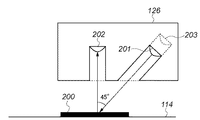
パッチセンサ126の一例を図2に示す。パッチセンサ126は、LED等の光源201と、光源201から照射され、パッチ画像200で反射した光を受光する濃度測定用受光素子202、光源201の光量を一定にする為に光源201の光量を直接受光する光量調整用受光素子203、で構成される。
An example of the
次に、デジタル複合機が行う、トナー補給処理、及び濃度階調補正処理について、図3のフローチャートを用いて説明する。なお、図3に示した各ステップにおける処理の主体は、コントローラ900である。 Next, toner replenishment processing and density gradation correction processing performed by the digital multi-function peripheral will be described with reference to the flowchart of FIG. Note that the subject of processing in each step shown in FIG.
先ずステップS301では、コントローラ900は、パッチ画像を生成する。そして生成したパッチ画像を、本来印刷対象として外部から取得した画像データに基づく印刷画像(出力画像)と共に、感光ドラム114上に形成する。そしてコントローラ900は、パッチセンサ126を制御し、パッチセンサ126は、感光ドラム114上のパッチ画像の濃度値を測定値として読み取る。
First, in step S301, the
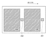
図4は、印刷画像とパッチ画像とが形成された感光ドラム114面の一例を示す図である。図4に示す如く、パッチ画像401,402は、印刷画像が形成されない領域に、任意のタイミング、任意の濃度レベルで形成される。なお、パッチ画像は印刷画像を形成する際に常に形成する必要はなく、例えばA4サイズの印刷画像10枚毎に一回形成するようにしても良い。また、パッチ画像の形成頻度は、要求される精度に基づいて可変であってもよい。また、パッチ画像の濃度は、重要視される一定の固定値であっても、可変であっても良い。
FIG. 4 is a diagram illustrating an example of the surface of the
パッチセンサ126は、感光ドラム114上に形成されたパッチ画像の濃度を読み取る。感光ドラム114上に形成された印刷画像は転写材121に転写され、パッチ画像はパッチセンサ126において濃度を検知された後、転写材121に転写されずクリーナ125によって掻き消される。
The
次に、ステップS302では、コントローラ900は、パラメータの検知または推定を行う。ここでパラメータとは、トナー濃度、トナー帯電量、画像形成装置内の温度・湿度、キャリアの劣化度などである。トナー濃度の検出は、光学反射光量検知方式やインダクタンス検知方式のセンサを利用することで可能である。トナー帯電量の検出は、電位センサを用いて算出する方法(特許文献3)などがある。温度・湿度の検出は一般的な方法でよい。キャリアの劣化度の検知は、プリント枚数のカウント値と予め測定しておいたカウント値と劣化度のLUTなどを用いることで可能である。
Next, in step S302, the
本実施例では、トナー濃度、トナー帯電量についてはセンサによる計測ではなく、推定するものとして説明し、その他の必要なパラメータについては検知可能なものとして説明する。 In this embodiment, the toner density and the toner charge amount are described as being estimated, not measured by a sensor, and other necessary parameters are described as being detectable.
画像形成対象となる画像データはデジタル複合機内の不図示のメモリ内に格納されている。従って、コントローラ900は先ず、この画像データを構成する各画素の画素値を参照し、それぞれの画素値の累積値(積算値)を求める。そして求めた累積値から、この画像データの印刷画像を形成するためのトナーの消費量を推測する。また、コントローラ900内は、不図示のトナー補給装置(ホッパー)から現像器117に補給されたトナー補給量を示すデータを取得する。
Image data to be image formed is stored in a memory (not shown) in the digital multi-function peripheral. Therefore, the
そしてコントローラ900は、トナー消費量、トナー補給量を用いて以下の式1、式2に基づく計算処理を行う。以下の計算式は「オブザーバ」と呼ばれるモデルで、オブザーバとは、制御工学におけるオブザーバに類するものである。
The
dx/dt =Ax+Bu (式1)
y =Cx+Du (式2)
ここで、このモデルは制御工学における状態空間モデルであり、式1は状態方程式、式2は出力方程式である。uは、推測したトナーの消費量と、コントローラ900が取得したトナー補給量と、を示す1×2行列である。xは、トナー濃度と、トナー帯電量と、を示す1×2行列(状態変数)である。yは、ある入力パッチ濃度レベルにおける出力パッチ濃度(出力)であり、A、B、C、Dはそれぞれ、モデルを定義するシステム行列、制御行列、観測行列、直達行列である。これらの行列は、デジタル複合機のトナー粒子の移流拡散やトナー帯電量の立ち上がり特性などにより決定される。この式1,2に基づく計算を行うことで、x、yの変動を予測することができる。次に、コントローラ900は、以下の式3に基づく計算処理を行う。
dx / dt = Ax + Bu (Formula 1)
y = Cx + Du (Formula 2)
Here, this model is a state space model in control engineering, where
dx/dt=Ax+Bu−L(yobsv−yplant) (式3)
ここでyobsvは、式2における出力パッチ濃度yであり、yplantは、パッチセンサ126が測定した濃度値であり、Lはオブザーバゲインである。オブザーバゲインは、yobsvとyplantとの差分から、モデル内の状態量のズレを補正するための行列である。このためオブザーバにより行列x、即ち、トナー濃度とトナー帯電量とをより確かに推定することができる。
dx / dt = Ax + Bu−L (y obsv −y plant ) (Formula 3)
Here, y obsv is the output patch density y in
次に、ステップS303では、コントローラ900は、次回の画像形成時における行列xを求める処理を行う。これは、時間経過に伴なってデジタル複合機内のパラメータが変動し、形成する画像の濃度に影響を与えるためである。ここでは一例として、次の画像形成処理中のある代表的なタイミングにおける行列xを求めるものとする。
Next, in step S303, the
先ず、コントローラ900は、現時点から次回の画像形成時までの間の時間tを求める。次に、コントローラ900は、メモリには、次回の画像形成対象の画像データが格納されているので、この画像データを構成する各画素の画素値を参照し、それぞれの画素値の累積値(積算値)を求める。そして求めた累積値から、この画像データに基づく画像を印刷するのに要するトナーの消費量を推測する。また、コントローラ900は、トナー補給量も確定する。これにより、確定したトナー補給量と求めたトナー消費量とを示す行列uを確定することができる。なお、この確定されたトナーの補給量は、任意の量でも良いが、説明を簡易にするため、トナー消費量と等しいものとする。つまり、トナー濃度を一定に制御すると、上記モデルは例えば図11に示したトナー帯電量の動きを予測することができる。
First, the
次に、この求めた行列uと、上記式1を用いて、次回の画像形成時における行列xを求める計算処理を再度行う。なお、係る計算処理では、前回の計算時の計算結果(行列x)を初期値として用いる。さらに、式(2)を用いて、求められた行列xから、次回の画像形成時における出力パッチ濃度yを算出する。
Next, the calculation process for obtaining the matrix x at the next image formation is performed again by using the obtained matrix u and
次に、ステップS304では、コントローラ900は、算出された次回の画像形成時における出力パッチ濃度yに基づき、γ変換器105が有するLUTを補正する。補正されたLUTは、次回の画像形成対象の画像データに対するγ変換で使用される。
In step S304, the
以上説明したように、本実施例によれば、トナー濃度の変動を予測し、階調補正条件を制御することができる。これにより、常時、濃度階調特性を補償することができる。なお、本実施例は、濃度階調特性を予測制御するものであるが、その他の一般的なフィードバック制御と併用しても良い。 As described above, according to the present embodiment, it is possible to predict fluctuations in toner density and control the tone correction conditions. Thereby, the density gradation characteristic can be compensated at all times. In this embodiment, the density gradation characteristic is predicted and controlled, but may be used in combination with other general feedback control.
また、本実施例では、パッチ画像の濃度測定のタイミングは任意のタイミングで行うものとしたが、予測値と実測値とのズレ量に応じてその測定頻度を変えるようにしても良い。また、測定値は濃度に限るものではなく、反射率、トナー重量、トナー帯電量等、パッチ画像の状態量が推定可能なものであればよい。 In this embodiment, the density measurement timing of the patch image is performed at an arbitrary timing. However, the measurement frequency may be changed according to the amount of deviation between the predicted value and the actual measurement value. The measured value is not limited to the density, but may be any value that can estimate the state quantity of the patch image, such as reflectance, toner weight, and toner charge amount.
また、本実施例では、パラメータの予測タイミングを、次の画像形成処理中のある代表的なタイミングとしたが、これに限定するものではない。例えば、パラメータの予測タイミングを複数設定し、それぞれのタイミングで予測した結果を平均し、その平均値をもって予測値としても良い。 In this embodiment, the parameter prediction timing is set to a representative timing during the next image forming process. However, the present invention is not limited to this. For example, a plurality of parameter prediction timings may be set, the results predicted at each timing may be averaged, and the average value may be used as the prediction value.
また、本実施例では、トナーの補給を任意に行うものとしたが、それぞれのタイミングで求めたパラメータ同士の差が最小になるようにトナー補給量を決定し、画像出力中の濃度変動を最小にする方法も考えられる。 In this embodiment, toner is replenished arbitrarily. However, the toner replenishment amount is determined so that the difference between parameters obtained at each timing is minimized, and the density fluctuation during image output is minimized. It is also possible to make it.
また、本実施例では、トナー濃度およびトナー帯電量を推定しているが、これらをセンサなどを用いて検知可能としてもよく、このとき状態空間モデルで近似可能であり、オブザーバを設計可能であれば、さらに他のパラメータを推定するものとしてもよい。 In this embodiment, the toner density and the toner charge amount are estimated. However, these may be detected using a sensor or the like, and can be approximated by a state space model and an observer can be designed. For example, other parameters may be estimated.
[実施例2]
本実施例に係る画像形成装置は、画像信号に対して画像処理条件を用いて画像処理を行う画像処理部と、画像処理された画像信号に基づき、制御されたプロセス条件を用いて、電子写真方式により出力画像を形成する画像形成部とを有する画像形成装置である。より詳しくは、感光体、誘電体等の像担持体上に電子写真方式、静電記録方式等で静電潜像を形成し、この静電潜像の階調特性を適宜補正し、この静電潜像を現像剤の補給を伴なう現像装置によって現像し、可視画像を形成する。図5は、本実施例に係る画像形成装置の構成例を示すブロック図である。
[Example 2]
An image forming apparatus according to the present embodiment includes an image processing unit that performs image processing on an image signal using an image processing condition, and an electrophotographic process that uses a controlled process condition based on the image signal subjected to the image processing. An image forming apparatus having an image forming unit that forms an output image by a method. More specifically, an electrostatic latent image is formed on an image carrier such as a photosensitive member or a dielectric by an electrophotographic method, an electrostatic recording method, or the like, and the gradation characteristics of the electrostatic latent image are corrected as appropriate. The electrostatic latent image is developed by a developing device accompanied by developer replenishment to form a visible image. FIG. 5 is a block diagram illustrating a configuration example of the image forming apparatus according to the present embodiment.
まず、コントローラ1001は、外部装置1003から画像信号を受け取り、プリント命令を発行する。外部装置1003は、図示しないハードディスクドライブ、コンピュータ、サーバ、ネットワークなどとのインターフェースを有し、画像信号の出力を行う。
First, the
γ変換部1101は、外部装置1003からの画像信号に対し、ルックアップテーブル(LUT)を用いてγ変換(第1の階調補正)を行う。次に、γ補正部1102は、γ変換部1101からの画像信号に対して、LUTを用いてγ補正(第2の階調補正)を行う。HT処理部1103は、γ補正部1102からの階調補正された画像信号に対してハーフトーン処理(HT処理)を行う。
The
PWM処理部1104は、ハーフトーン処理が施された画像信号と、所定周期の三角波信号と、の比較を行い、パルス幅変調されたレーザ駆動信号を出力する。このレーザ駆動信号はプリンタエンジン1002に出力される。レーザダイオード1201は、レーザ駆動信号を受けてレーザ光を放射する。放射されたレーザ光は、ポリゴンミラー(不図示)、fθレンズ(不図示)、反射ミラー1202を経て、矢印方向に回転している像担持体である感光ドラム1203上に照射される。これにより感光ドラム1203上には静電潜像が形成される。
The
感光ドラム1203は、露光器1204で均一に除電された後、帯電器1205により均一に帯電される。その後、先のレーザ光の照射を受けて、感光ドラム1203上には、印刷画像に応じた静電潜像が形成される。そして、この静電潜像は、現像器(現像部)1206から供給されるトナーによって可視画像(トナー像)として現像される。
The
このとき、現像器1206には静電潜像形成条件に応じたDCバイアス成分と現像効率を向上させるためのACバイアス成分とが重畳され、印加される。現像器1206は、複数の攪拌スクリュ1401と現像スリーブ1402とから構成されている。現像器1206内には、図示しない現像剤(キャリア)とトナーとが蓄えられている。攪拌スクリュ1401は、その駆動によりキャリアとトナーとを攪拌し、トナーを摩擦帯電させる。現像スリーブ1402は、帯電したトナーおよびキャリアを表面に付着させながら回転し、感光ドラム1203上の静電潜像にトナーを供給する。
At this time, a DC bias component corresponding to the electrostatic latent image forming condition and an AC bias component for improving development efficiency are superimposed and applied to the developing
現像されたトナー像は、複数のローラ間に加張されて無端駆動されるベルト状の転写材担持体(転写ベルト)1207上に、一次転写器1208の作用によって転写される。転写材担持体1207に転写されたトナー像は、二次転写器1209により転写材1210に転写される。転写材1210は搬送され、定着器1211を通り、トナー像を転写材1210上に定着させる。そして転写材1210は排出される。
The developed toner image is transferred onto a belt-shaped transfer material carrier (transfer belt) 1207 that is stretched between a plurality of rollers and driven endlessly by the action of the
また、感光ドラム1203上に残った残留トナーはその後、クリーナ1212で掻き落とされ、回収される。また、転写材1210が分離された後、残留している転写材担持体1207上の残留トナーは、ブレード等のクリーナ1213によって掻き落とされる。
The residual toner remaining on the
なお、図5では、説明を簡単にするために、単一の画像形成ステーション(感光ドラム1203、帯電器1205、現像器1206等を含む)のみを図示している。しかし、カラー形成を行う場合には、例えばシアン、マゼンタ、イエロー、ブラックの各色に対する画像形成ステーションが転写材担持体1207上にその移動方向に沿って順次配列される。若しくは、1つの感光ドラム1203の周囲に各色の現像器1206を周囲に沿って配列させる。若しくは、回転可能な筐体にイエロー、マゼンタ、シアン、およびブラックの各色の現像器1206を配置させる。即ち、所望の現像器1206を感光ドラム1203に対向させ、所望の色の現像を行うようにする。図12は、4つの画像形成ステーションを順次配列した画像形成装置の構成例を示す図である。コントローラ1001は、次の各部から構成される。
In FIG. 5, only a single image forming station (including the
・ 画像信号を各色に分解する色分解部1108
・ 各色の信号処理部1100a、1100b、1100c、1100d(γ変換部1101、γ補正部1102、HT処理部1103、PWM処理部1104、ビデオカウント部1105、補正量算出部1106、パッチデータ記憶部1107を含む)
各画像形成ステーション1200a、1200b、1200c、1200dは、それぞれ対応する信号処理部により制御される。なお、それぞれの画像形成ステーションは、レーザダイオード1201、反射ミラー1202、感光ドラム1203、露光器1204、帯電器1205、現像器1206、クリーナ1212、補給器1217、トナータンク1218から構成される。
A
Each of the
また、現像器1206と転写材担持体1207の対向部との間の位置には、パッチセンサ1214(実施例1と同一の構成)が設けられている。パッチセンサ1214は、感光ドラム1203上に現像された濃度検知用現像像(パッチ)の濃度を検知し、現像器1206へのトナー補給の制御、およびγ変換部1101が有するLUT(ルックアップテーブル)の補正を行う。トナー補給の制御とLUTの補正による階調補正の詳細については後述する。
Further, a patch sensor 1214 (same configuration as that of the first embodiment) is provided at a position between the developing
次に、画像形成装置が行うトナー補給処理について説明する。ビデオカウント部1105は、HT処理部1103が出力する1ページ当りの画像信号を積算し、その積算値をビデオカウント値VCとして補給量算出部1215へ出力する。ビデオカウント値VCは、1ページ分の画像を構成する各画素の信号値ni,j(i、jはそれぞれ縦横の座標)の積算値であり、式(4)により算出される。
Next, toner supply processing performed by the image forming apparatus will be described. The
VC=n1,1+n1,2+n1,3+・・・n2,1+n2,2+n2,3+・・・nw,h 式(4)
なお、wは画像の幅、hは画像の高さである。補給量算出部1215は、ビデオカウント値VCから、画像形成装置が1ページの印刷で消費するトナー量Tを式(5)を用いて予測する。
VC = n 1,1 + n 1,2 + n 1,3 +... N 2,1 + n 2,2 + n 2,3 +... N w, h formula (4)
Note that w is the width of the image and h is the height of the image. The supply
T=VC×k 式(5)
kは単位信号値あたりのトナー重量をあらわす係数である。実際は、消費されるトナー量は温度、湿度、現像器1206の状態などにより変動する。したがって、予測されたトナー量は、実際に消費されるトナー量とは異なり、誤差を含む。
T = VC × k Formula (5)
k is a coefficient representing the toner weight per unit signal value. Actually, the amount of toner consumed varies depending on temperature, humidity, the state of the developing
補給量補正部1216は、パッチセンサ1214で検出したパッチ濃度を基に、トナー補給量の調整を行い、調整されたトナー補給量に応じた補給モータ回転信号を出力する。補給モータ回転信号は、補給器1217に備わっている補給モータを回転駆動させるための信号であり、この信号が示す補給モータ回転数Nは、式(6)により算出できる。
The supply
N=(T+kd×(Dtarget―D)+Trem)÷Tdiv 式(6)
Trem(n+1)=(T+kd×(Dtarget―D)+Trem)―N×Tdiv
ここで、“÷”は剰余演算記号であり、Tdivは補給器1217が有する補給モータの1回転あたりのトナー補給量、Dはパッチセンサ1214で測定したパッチ濃度値である。また、Dtargetは目標とするパッチ濃度値、kdは補給調整量を決定する為の係数、Tremは前回の「トナータンク1218から現像器1206に補給されるプリント一枚あたりのトナー補給量Th」算出時での余りを表す。
N = (T + k d × (D target −D) + T rem ) ÷ T div equation (6)
T rem (n + 1) = (T + k d × (D target −D) + T rem ) −N × T div
Here, “÷” is a remainder calculation symbol, T div is the toner replenishment amount per rotation of the replenishment motor of the
補給器1217が、消費するトナー量と同量のトナーを補給することにより、現像器1206内のトナー量を常に一定にすることが望ましい。しかし、補給量算出部1215で算出されるトナー量、および補給器1217で補給されるトナー量は誤差を含む。この誤差を補償するために、パッチ濃度を利用した補給量調整を行う。これは、現像器1206に残存するトナー量と、現像されるパッチ画像の濃度と、の間の相関性を利用したものである。パッチセンサ1214で測定したパッチ濃度が想定より低ければ、現像器1206内のトナー量が減少している可能性が高いために補給量を増やし、逆にパッチ濃度が高ければ、補給量を減らす。以上の調整により、現像器1206内のトナー量を一定に保っている。また、補給器1217は一回転単位でしか駆動できないため、補給できなかったトナー量は、以降の計算に持ち越される。
It is desirable that the amount of toner in the developing
次に、補給器1217は、補給量補正部1216から出力される補給モータ回転信号に従って補給モータを、この信号が示す補給モータ回転数Nだけ回転させ、トナータンク1218に蓄えられているトナーを現像器1206内に補給する。これにより、指示されたトナー補給量に基づきトナーを補給することができる。
Next, the
なお、補給器1217の駆動単位を一回転としているのは、スクリューのブレード(所謂歯の部分)が一回転で同じ場所に戻るために補給量が安定するからであり、回転位相による補給量の差を考慮した補給制御や他の補給方式を用いた場合はこの限りではない。
The reason why the drive unit of the
次に、画像形成装置が行う階調変換処理について説明する。階調変換処理はγ変換部1101とγ補正部1102とで2段階の処理が行われる。まず、γ変換部1101で使用するLUTの作成方法について、図7(a)のフローチャートを用いて説明する。
Next, gradation conversion processing performed by the image forming apparatus will be described. The gradation conversion processing is performed in two steps by the
画像形成装置は固有の階調特性を有しており、外部装置1003からの画像信号をそのままHT処理部1103、PWM処理部1104を介して出力すると、画像信号とその出力濃度との関係は、例えば、図6(a)のγ変換前の特性500に示すようになる。通常、画像形成装置の階調特性としては、入力信号に対する出力画像の濃度もしくは明度などに対して線形なものが好まれる。そこでコントローラ1001は、所望の階調特性を得るためにγ-LUTを作成する。
The image forming apparatus has inherent gradation characteristics. When the image signal from the
まず、コントローラ1001は、予め設定された条件に基づき、γ-LUTの作成を行うか否かを判断する(ステップS601)。例えば、画像形成装置の起動直後や一定のプリント数、例えば5000枚のプリントを行った後など、著しく階調特性が変化している可能性がある場合には、γ-LUTの作成を行うと判断する。係る判断の結果、γ-LUTを作成すると決定した場合には、ステップS602に進む。一方、γ-LUTを作成しないと決定した場合には、本処理を終了する。本実施例では、γ-LUTを作成すると決定した場合は、プリント命令に基づく画像出力を停止し、複数階調のパッチを形成し、γ-LUTの作成処理を行う。
First, the
ステップS602において、パッチデータ記憶部1107は、複数階調のパッチデータをHT処理部1103に出力する。パッチデータは、階調特性を算出するために入力信号値の間隔が均等に並べられた17階調のパッチ(8bitであれば、0、16、32・・・255)で構成される。また、それぞれのパッチのサイズは、パッチセンサ1214で濃度を検出可能なサイズ、例えば1cm四方である。もちろん、パッチの階調数やパッチの数については特に限定するものではない。
In step S602, the patch
そして、感光ドラム1203上に潜像を形成するための上記の動作により、HT処理部1103でハーフトーン処理が施されたパッチデータを用いて、感光ドラム1203上に複数階調のパッチの潜像を形成する(ステップS603)。次にパッチセンサ1214は、感光ドラム1203上の各パッチの濃度を測定する(ステップS604)。
Then, by using the patch data that has been subjected to the halftone process by the
γ変換部1101は、ステップS604で測定された各パッチの測定濃度を示すパッチ濃度信号をパッチセンサ1214から受け、このパッチ濃度信号に基づく画像形成装置の階調特性からγ-LUTを作成し、記憶する(ステップS605)。γ-LUTは、ステップS604で得られた各パッチの濃度に基づき求められたγ変換前の特性(点線)から、γ変換前の特性と逆の特性を持つ特性(実線)を算出し、この逆の特性を持つ特性に基づき作成される。図6(a)に、変換前の特性500と、その逆特性を持つγ-LUT502と、理想特性501と、の関係の模式図を示す。
The
γ変換部1101で行われるγ-LUTの作成は、複数のパッチ出力及び濃度測定を行うための時間を要する。このため、γ変換部1101でのγ−LUT作成処理を、プリント1枚毎等、高い頻度でγ変換部1101でのγ−LUT作成処理を行うと、著しく生産性を低下させる。また、γ-LUTの作成の際に、トナーの消費や補給を伴うため、厳密には画像形成装置の階調特性を変化させてしまう。
The creation of the γ-LUT performed by the
そこで、本実施例では、γ補正部1102により、入力されたデータに基づいて階調特性を予測することにより、パッチ出力等の時間を要さず、高い頻度で階調特性の補正を行う。つまり、画像形成装置の経時劣化など長い時間を経て変動した基本的な階調特性をγ変換部1101により補正し、短い時間で変動した階調特性をγ補正部1102により補正する。
Therefore, in this embodiment, the
このように、γ補正部1102は、短い時間で発生する変動、すなわち、トナーの攪拌やトナー補給、現像によるトナーの消費などに起因する現像トナー量の変動を補償するためのものである。このようなトナーの状態に起因する変動は、図11を用いて説明したように、数枚の印字出力を行っているような短時間でも発生してしまうため、プリント1枚毎に、補正量算出部1106により補正量を算出し、階調特性の補正を行う。
As described above, the
γ補正部1102は例えば、(n−1)枚目のプリント開始時のトナー帯電量の予測値から、(n−1)枚目のプリントにおけるエンジンのプロセス変動情報を用いて(n−1)枚目のプリント終了時(n枚目のプリント開始時)のトナー帯電量の予測を行う。ここで、プロセス変動情報とは、トナー消費量、補給モータ回転数、現像モータ回転数の変動情報を示す。そして、この予測されたトナー帯電量に基づいて出力濃度を算出し、階調変換条件(γ-LUT)を作成する。
For example, the
γ補正部1102における階調変換処理について、図7(b)のフローチャートを用いて説明する。まず、コントローラ1001は、予め設定された条件に基づき、トナー帯電量の予測を行うか否かを判断する(ステップS701)。予測を行う条件については後述する。係る判断の結果、トナー帯電量を予測しないと決定した場合には本処理を終了させ、トナー帯電量を予測すると決定した場合には処理はステップS702に進む。
The gradation conversion processing in the
補正量算出部1106は、ビデオカウント部1105からビデオカウント値VCを受けると、現像器1206で消費されるプリント一枚あたりのトナーの消費量Tを予測する(ステップS702)。トナー消費量Tは、補給量算出部1215と同様に、式(5)により求まる。
When the correction
なお、本実施例では、補正量算出部1106が、ビデオカウント部1105からビデオカウント値VCを取得してトナー消費量Tを算出するが、補給量算出部1215からトナートナー消費量Tを取得するようにしても構わない。
In this embodiment, the correction
補正量算出部1106は、補給量補正部1216からの補給モータ回転信号(補給モータ回転数N)を用いて、トナータンク1218から現像器1206に補給されるプリント一枚あたりのトナー補給量Thを式(7)を用いて予測する(ステップS703)。
The correction
Th=N×Tdiv 式(7)
次に補正量算出部1106は、現像器1206から攪拌スクリュ1401の回転時間を受け取り、攪拌時間ton(n-1)とする(ステップS704)。ここで、補正量算出部1106がステップS702、S703、S704のそれぞれにおいて取得する情報の詳細について、図8に示す各処理の順序を示す模式図を用いて説明する。
Th = N × T div formula (7)
Next, the correction
図8の最上段は、プリント命令の発行タイミングを示しており、発行タイミング信号の立ち上がりP(n)(n枚目のプリント命令)に対して、画像形成装置が動作する。まず、不図示の制御部からP(n)が発行されると、コントローラ1001において画像信号の処理が開始される。そして、E(n)のタイミングで、コントローラ1001から出力されるレーザー駆動信号に基づきレーザダイオード1201が露光処理を行う。ビデオカウント部1105にてビデオカウント値の算出を開始し、露光処理終了の時点801でn枚目のプリントのビデオカウント値が確定する。また、露光処理により感光ドラム1203上に形成された潜像が現像器1206に対向するタイミングに合わせて、不図示の制御部から現像モータ回転信号DEV(n)が出力される。現像器1206は、現像モータ回転信号DEV(n)を受けて、攪拌スクリュ1401および現像スリーブ1402を駆動させる。攪拌スクリュ1401の回転時間(撹拌時間ton)は、不図示の制御部により実行される攪拌時間決定機能により、感光ドラム1203の回転速度とP(n)発行時に取得されるn枚目の画像のサイズとから決定される。
The top row of FIG. 8 shows the print command issue timing, and the image forming apparatus operates in response to the rise P (n) (n-th print command) of the issue timing signal. First, when P (n) is issued from a control unit (not shown), the
また、現像モータ回転信号DEV(n)の立ち上がりに合わせたタイミングH(n)で補給モータが作動し、現像器1206にトナーを補給する。n毎目の露光処理の立ち上がり前のタイミング802は、P(n)を受けてγ補正部1102での処理が始まるタイミングであり、γ補正部1102の階調変換に用いられるγ-LUTが書き換え終わっていなければならない。ステップS702、S703、S704において取得する情報はこれ以前に取得する情報である。
Further, the replenishment motor operates at the timing H (n) in synchronization with the rising of the developing motor rotation signal DEV (n) to replenish the
ステップS702にて取得するビデオカウント値VCは、(n−1)枚目の露光タイミングE(n−1)の立下りタイミング803時には確定する(n−1)枚目のビデオカウント値(すなわち、(n−1)枚目の印刷におけるトナー消費量)である。
The video count value VC acquired in step S702 is determined at the falling
ステップS703にて取得するトナー補給量Thは、補給モータ回転タイミングH(n−1)で補給されるトナー量であり、H(n−1)の立ち上がりタイミング804で確定している補給モータ回転数N(n−1)を用いて算出する。
The toner replenishment amount Th acquired in step S703 is the amount of toner replenished at the replenishment motor rotation timing H (n-1), and the replenishment motor rotation speed determined at the rising
ステップS704にて取得する攪拌時間tonは、現像モータ回転信号DEV(n−1)の駆動時間であるが、この時間はプリント命令P(n−1)の発行直後には確定しているため、これを用いる。 Agitation time t on the acquired in step S704 is the driving time of the developing motor rotation signal DEV (n-1), since the established immediately after the issuance of the time the print instruction P (n-1) Use this.
次に補正量算出部1106は、(n−1)枚目のプリントにおける上記の情報を用いて、(n−1)枚目のプリント終了時(n枚目のプリント開始時)のトナー帯電量の予測を行う(ステップS705)。補正量算出部1106は、以下の式(8)および式(9)により、現像器1206内の平均トナー帯電量yを算出する。本実施例では、トナー帯電量の予測において、制御工学における状態空間モデルを使用する。状態空間モデルは、入力と出力と状態変数を使った一階連立微分方程式で表した数学的モデルである。つまり、本実施例では、現像器1206内のトナー帯電量の変動特性を連立微分方程式で近似し、式(8)および式(9)で示される状態空間モデルを使用して、n枚目のプリント開始時におけるトナー帯電量yを推測する。
Next, the correction
dx/dt =Ax+Bu 式(8)
y =Cx+Du 式(9)
ここで、uは単位時間あたりの補給トナー量{Th/ton(n-1)}と、単位時間あたりの消費トナー量{T/ton(n-1)}からなる1×2行列である。係る行列uは、ステップS702、S703、S704のそれぞれで算出するトナー消費量T(n-1)、トナー補給量Th(n-1)、攪拌時間ton(n-1)から算出できる。
dx / dt = Ax + Bu Formula (8)
y = Cx + Du Formula (9)
Here, u is a 1 × 2 matrix composed of a replenishing toner amount {Th / ton (n−1) } per unit time and a consumed toner amount {T / ton (n−1) } per unit time. is there. The matrix u can be calculated from the toner consumption amount T (n−1), the toner replenishment amount Th (n−1), and the stirring time ton (n−1) calculated in steps S702, S703, and S704, respectively.
xは、トナー濃度と、トナー帯電量と、を示す1×2行列(状態変数)である。A、B、C、Dはそれぞれ、モデルを定義するシステム行列、制御行列、観測行列、直達行列である。つまり式(8)および式(9)は、現像器1206内のトナー帯電量の変動特性を連立微分方程式で近似したものであり、A、B、C、Dの各行列は予め実験などによって一意の値を利用することが可能である。例えば、図11に示すトナー消費およびトナー補給が行われた場合のトナー帯電量の変動は、感光ドラム1203表面の電位測定および現像トナー像の重量測定により事前に測定することができる。制御工学におけるシステム同定を用いることで、測定データからA、B、C、Dの各行列を求めることが可能である。
x is a 1 × 2 matrix (state variable) indicating the toner density and the toner charge amount. A, B, C, and D are a system matrix, a control matrix, an observation matrix, and a direct matrix that define the model, respectively. In other words, the equations (8) and (9) are obtained by approximating the fluctuation characteristics of the toner charge amount in the developing
上記の計算をより詳細に説明する。図8に示すton(n-1)は、(n−1)枚目のプリントについてのトナーの消費、補給、攪拌によりトナー帯電量が変化する時間である。補正量算出部1106は、時間ton(n-1)におけるトナー帯電量の変化を、式(8)および式(9)をton(n−1)/Δt回繰り返すことにより求める。Δtは計算を行う単位時間である。
The above calculation will be described in more detail. Ton (n−1) shown in FIG. 8 is a time during which the toner charge amount changes due to toner consumption, replenishment, and stirring for the (n−1) th print. The correction
現像モータの回転開始時刻807をt=0とすると、その時点でのトナー帯電量y(n−1)は前回の計算によって予測されている。また、その計算に伴い、状態変数x0も保持されている。次に補正量算出部1106は、時刻808(t1=Δt)における状態変数x1を式(8)により算出する。この計算は式(10)に書き直すことができる。
Assuming that the rotation start
x1=x0+Ax0+Bu 式(10)
同様に、時刻809(t2=t1+Δt)における状態変数x2を求めるための計算は式(11)で記述できる。
x1 = x0 + Ax0 + Bu Formula (10)
Similarly, the calculation for obtaining the state variable x2 at time 809 (t2 = t1 + Δt) can be described by equation (11).
x2=x1+Ax1+Bu 式(11)
同様に計算を繰り返し、時刻811の状態変数x4が算出された状態で、式(9)の計算を行う。この計算は式(12)に書き直すことができる。
x2 = x1 + Ax1 + Bu Formula (11)
Similarly, the calculation is repeated, and the calculation of Expression (9) is performed with the state variable x4 at
y4=Cx4+Du 式(12)
時刻811から時刻806の間の時間ではトナー帯電量は変化しないものとして、時刻806(即ちn枚目プリント開始時)のトナー帯電量を以下の式(13)に示す如く、予測することができる。
y4 = Cx4 + Du Formula (12)
Assuming that the toner charge amount does not change during the time between
y(n)=y4 式(13)
なお、状態変数x4は、次回の計算のために記憶される。次に、補正量算出部1106が行うトナー帯電量予測処理について説明する。図9(a)は、画像形成装置が行うプリント処理と現像モータの駆動との関係を表す図である。現像モータはプリント処理に伴い動作するが、画像形成装置の調整、例えば、起動直後の動作確認やγ変換部1101で使用するLUTの作成時などにも動作する。これにより、トナー帯電量は変化する。従って、トナー帯電量の予測を行う条件は、図9(a)の現像モータの駆動前(プリント処理前のタイミング901と他の処理により現像モータが回転する前のタイミング902)となる。そして、この条件が満たされると、ステップS702〜S705の処理を行うことで状態変数xおよびトナー帯電量yの値を更新する。
y (n) = y4 Formula (13)
The state variable x4 is stored for the next calculation. Next, toner charge amount prediction processing performed by the correction
次に、コントローラ1001は、γ-LUTの作成を行うか否かを判断する(S706)。ここでは、プリント1枚毎に補正を行うため、プリント処理前のタイミング901で処理を行うものとする。つまり、図9のプリント処理前のタイミング901では、ステップS702〜S705で状態変数xおよびトナー帯電量yの値を更新し、且つステップS707〜S709でγ補正部1102のγ-LUT作成を行う。一方、プリント処理は行わないが、現像モータが回転するタイミング902では、ステップS702〜S705の処理のみを行い、状態変数xおよびトナー帯電量yの値の更新を行う。
Next, the
このとき、特に、γ変換部1101のγ−LUTを書き換えるためのパッチ作成時のトナー帯電量yは基準トナー帯電量ynormとして記憶する。例えば図9に示す、プリントを伴わない現像モータ回転期間903において、ステップS601〜S605の処理が行われるとすると、タイミング902での予測トナー帯電量ynormによってγ変換部1101のγ-LUTが書き換わる。これにより、理想の階調特性が得られる。以降の処理ではこれを基準状態とし、ステップS707〜S709の処理においては、基準状態からのトナー帯電量の変動を基に階調特性の補正を行う。
At this time, in particular, the toner charge amount y at the time of creating a patch for rewriting the γ-LUT of the
なお、本実施例ではプリント一枚に対して、現像モータの起動と停止が一度ずつ行われるものとして説明している。しかし、図9(b)に示すような複数のプリントに対して現像モータが回転し続ける画像形成装置においても、各プリント開始時のトナー帯電量の予測は可能である。また、複数色の画像形成ステーションを回転させて順次使用する構成の画像形成装置においては、図9(c)に示すように、各色独立に現像モータが動作する。この場合は、各色別のタイミングのトナー帯電量予測を行う。 In this embodiment, it is assumed that the developing motor is started and stopped once for each print. However, even in an image forming apparatus in which the developing motor continues to rotate for a plurality of prints as shown in FIG. 9B, the toner charge amount at the start of each print can be predicted. Further, in an image forming apparatus configured to rotate and sequentially use a plurality of color image forming stations, a developing motor operates independently for each color as shown in FIG. 9C. In this case, the toner charge amount prediction at the timing for each color is performed.
次に補正量算出部1106は、予測されるトナー帯電量yと基準トナー帯電量ynormとを用いて、式(14)に従った計算処理を行うことで、単位面積あたりのトナー重量変動量ΔMを求める(ステップS707)。
Next, the correction
ΔM=M−Mnorm=ky/y−ky/ynorm 式(14)
ここで、トナー重量Mは、ある決められた静電潜像を現像したときに現像されるトナー量を表しており、kyはトナー帯電量とトナー重量との関係を示す比例定数である。これは、ある決められた静電潜像に現像されるトナー重量Mは、トナー帯電量yと反比例する関係を示している。本実施例では、潜像は、最大の入力信号値255で形成される最高濃度部を形成するための潜像とする。なお、他の濃度部のトナー重量を求めるようにしても構わない。
ΔM = M−M norm = ky / y−ky / y norm formula (14)
Here, the toner weight M represents the amount of toner developed when a predetermined electrostatic latent image is developed, and ky is a proportional constant indicating the relationship between the toner charge amount and the toner weight. This indicates that the toner weight M developed into a predetermined electrostatic latent image is inversely proportional to the toner charge amount y. In this embodiment, the latent image is a latent image for forming the highest density portion formed with the maximum input signal value 255. Note that the toner weight of other density portions may be obtained.
次に補正量算出部1106は、単位面積あたりのトナー重量変動量ΔMを出力濃度変動ΔODに変換する(ステップS708)。単位面積あたりのトナー重量Mと出力濃度ODとの間の関係は、同一の転写材1210を用いる場合には一意に決まっているため、ステップS708における変換は、予め作成したLUTや変換式を用いることで容易に行うことができる。
Next, the correction
次にγ補正部1102は、補正量算出部1106から入力画像信号の最大値255における出力濃度変動ΔODを受け取り、γ−LUTを作成する(ステップS709)。図6(b)は、トナー帯電量による階調特性変動の模式図である。入力画像信号の最大値255の濃度変動とその他の階調の濃度変動の関係は、潜像とトナー帯電量とトナー重量の関係から一意に決まる。このため、ある一階調の濃度(ここでは最大濃度)が分かれば階調特性全体が予測できる。γ補正部1102は、得られた階調特性と逆の特性を持つγ-LUTを作成し、記憶する。また、このγ-LUTを用いてγ変換処理を行う。これによりトナー帯電量の変動による濃度階調特性の変化を補正することが可能になる。
Next, the
以上説明したように、本実施例によれば、トナーの消費量およびトナーの補給量およびトナーの攪拌時間からトナー帯電量の変動を予測し、濃度階調特性を予測することで、濃度階調補正を行うことができる。これにより、常時、濃度階調特性が安定した出力画像を得ることができる。そして、画像形成装置の経時劣化など長い時間を経て変動した基本的な階調特性をγ変換部1101により補正し、短い時間で変動した階調特性をγ補正部1102により補正することができる。これにより、パッチ作成によるスループットを落とさずに、常に、階調特性を所望の特性に維持することができる。
As described above, according to the present embodiment, the density gradation characteristic is predicted by predicting the fluctuation of the toner charge amount from the toner consumption amount, the toner replenishment amount, and the toner agitation time, and by predicting the density gradation characteristic. Correction can be performed. Thereby, it is possible to always obtain an output image with stable density gradation characteristics. Then, basic gradation characteristics that have changed over a long period of time, such as deterioration over time of the image forming apparatus, can be corrected by the
なお、本実施例では、フィードバック制御による階調補正制御として図7(a)に示す方法を用いたが、プリント間にパッチを形成し、その濃度に応じて階調特性制御を行うなど、その他のフィードバック制御と併用しても良い。スループットを落とさずにプリント間でパッチを形成する場合、形成できるパッチの数が限られる。したがって、図7(a)に示すような階調補正制御を行うためには、複数毎のプリントが必要となる。そこで、図7(b)に示す階調補正制御が必要となる。 In this embodiment, the method shown in FIG. 7A is used as gradation correction control by feedback control. However, a patch is formed between prints and gradation characteristic control is performed according to the density. The feedback control may be used together. When patches are formed between prints without reducing throughput, the number of patches that can be formed is limited. Therefore, in order to perform the gradation correction control as shown in FIG. Therefore, the tone correction control shown in FIG. 7B is necessary.
[実施例3]
実施例2では、γ-LUTを利用して階調補正を行う方法について説明した。本実施例では、レーザ強度の補正により階調特性を補正する例について説明する。実施例3における画像形成装置の構成例を示すブロック図を図13(a)に示す。なお、図13(a)に示した構成は、図5の構成からγ補正部1102を削除すると共に図5の構成に強度補正部1300を加えた以外は、図5の構成と同一である。従って、以下では、強度補正部1300の動作について説明する。
[Example 3]
In the second embodiment, the method of performing gradation correction using the γ-LUT has been described. In this embodiment, an example in which the gradation characteristics are corrected by correcting the laser intensity will be described. FIG. 13A is a block diagram illustrating a configuration example of the image forming apparatus according to the third embodiment. The configuration shown in FIG. 13A is the same as the configuration in FIG. 5 except that the
強度補正部1300は、補正量算出部1106から入力画像信号の最大値255におけるトナー重量変動量ΔMを受け取り、以下の式(15)を計算することで、補正係数kpを算出する。
The
kp=1/(1+ΔM/Mnorm) 式(15)
ここで、Mnormは、最大値255における単位面積あたりの目標トナー重量である。強度補正部1300は、入力信号に補正係数Kpを乗算し、PWM処理部1104に出力する。
kp = 1 / (1 + ΔM / M norm ) Equation (15)
Here, M norm is the target toner weight per unit area at the maximum value 255. The
上記の処理によりレーザダイオード1201の発光強度および感光ドラム1203に形成される潜像が変化する。通常、潜像の強度が現像されるトナー重量と比例し、トナー帯電量と現像されるトナー重量が反比例する。このため、トナー帯電量の変化を潜像の強度で補正することが可能である。以上により、常時、濃度階調特性が安定した出力画像を得ることが可能となる。
The light emission intensity of the
[変形例]
上記実施例では、γ-LUTを作成する場合を説明したが、係数などの他の補正条件を作成するようにしても構わない。例えば、実施例2の図7(a)では図6(a)を実現するような多次元の関数を算出し、図7(b)では図6(b)を実現するような係数を算出するようにしても構わない。
[Modification]
In the above embodiment, the case where the γ-LUT is created has been described, but other correction conditions such as a coefficient may be created. For example, in FIG. 7A of the second embodiment, a multidimensional function that realizes FIG. 6A is calculated, and in FIG. 7B, a coefficient that realizes FIG. 6B is calculated. It doesn't matter if you do.
また、上記実施例ではγ補正を制御する例を説明したが、HT(ハーフトーン)など階調を制御できる他の画像処理条件を制御するようにしても構わない。また、画像処理条件だけでなく、補正量算出部1106によって予測されたトナー帯電量またはトナー重量に基づきプロセス条件を制御するようにしても構わない。例えば、図13(b)に示すブロック図のように、帯電器1205、現像器1206を制御し、感光ドラム1203の帯電量や現像バイアスを調整することにより所望の潜像を得ることが可能である。また、画像処理条件とプロセス条件とを組み合わせてより高精度な制御を行うようにしても構わない。
In the above embodiment, an example of controlling the γ correction has been described. However, other image processing conditions such as HT (halftone) that can control the gradation may be controlled. In addition to the image processing conditions, the process conditions may be controlled based on the toner charge amount or the toner weight predicted by the correction
また、上記実施例では、トナー消費量の算出をビデオカウント値と比例するものとしているが、画素値の密集度などを考慮する方法や、ビデオカウント値とトナー消費量の関係を予めLUTとして記憶するなどして算出する方法など利用することが可能である。また、ビデオカウント値をHT処理後の信号積算値としているが、γ補正処理後の信号を利用する方法でも構わない。 In the above embodiment, the calculation of toner consumption is proportional to the video count value. However, a method that considers the density of pixel values and the relationship between the video count value and the toner consumption are stored in advance as an LUT. It is possible to use a method of calculating by doing so. Further, although the video count value is the signal integrated value after the HT processing, a method using the signal after the γ correction processing may be used.
また、上記本実施例では、トナー補給量をビデオカウント値とパッチ濃度により決定するとしたが、現像器内のトナー量を検出するセンサを利用する等の方法を用いても構わない。 In the present embodiment, the toner replenishment amount is determined by the video count value and the patch density. However, a method using a sensor for detecting the toner amount in the developing unit may be used.
また、上記実施例では、現像モータ駆動に合わせてトナー帯電量が変動するものとして説明したが、駆動の伴わない放置時間が長期にわたる場合にトナーが除電される場合があるため、これを考慮してトナー帯電量を求めることも可能である。 In the above-described embodiment, the toner charge amount varies according to the driving of the developing motor. However, the toner may be removed when the toner is left unattended for a long time. Thus, the toner charge amount can be obtained.
また、上記実施例では、トナー帯電量の予測において状態空間モデルを使用したが、これに類する伝達関数、微分方程式など他の近似モデル(関数モデル)を用いることも可能である。また、トナー帯電量の予測を行うための物理シミュレーションや予め行った実験結果を用いる方法も考えられる。例えば、予め行った実験結果をLUTにした場合、トナー帯電量、トナー補給量、トナー消費量を入力とし、単位時間後のトナー帯電量の変化量を出力とする三次元LUTを用いることで同様の処理結果を得ることが可能である。 In the above embodiment, the state space model is used for predicting the toner charge amount. However, other approximate models (function models) such as a transfer function and a differential equation can be used. Further, a method of using a physical simulation for predicting the toner charge amount or a result of an experiment performed in advance can be considered. For example, when an LUT is used as the result of an experiment conducted in advance, the same is achieved by using a three-dimensional LUT that inputs toner charge amount, toner replenishment amount, and toner consumption amount, and outputs the change amount of toner charge amount after unit time This processing result can be obtained.
また、上記実施例2及び実施例3では、プリント1枚ごとに図7(b)のフローチャートに従ったγ-LUT作成処理を行うが、他の所定間隔ごとに推測プリントn枚ごとや、所定の画像領域ごとにγ-LUTを作成するようにしても構わない。 Further, in the second and third embodiments, the γ-LUT creation process is performed for each print according to the flowchart of FIG. 7B. A γ-LUT may be created for each image area.
Claims (5)
前記画像処理された画像信号に基づき、制御されたプロセス条件を用いて、電子写真方式により画像を形成する画像形成手段とを有する画像形成装置であって、
指示されたトナー補給量に基づき現像手段にトナーを補給する補給手段と、
前記補給されたトナーを攪拌し、感光ドラムの上に形成された静電潜像を現像する前記現像手段と、
画像を示す画像データから該画像を出力するためのトナー消費量を予測するトナー消費量の予測手段と、
前記画像を示す画像信号から前記トナー補給量を決定するトナー補給量の決定手段と、
前記現像手段においてトナーを攪拌する時間を取得する取得手段と、
前記予測されたトナー消費量、前記トナー補給量および前記攪拌する時間を使用して、トナー帯電量を推測し、画像処理条件およびプロセス条件の少なくとも1つを制御する制御手段と
を有することを特徴とする画像形成装置。 Image processing means for performing image processing on image signals using image processing conditions;
An image forming apparatus having an image forming means for forming an image by an electrophotographic method using a controlled process condition based on the image signal subjected to the image processing,
Replenishing means for replenishing toner to the developing means based on the instructed toner replenishment amount;
The developing means for agitating the supplied toner and developing an electrostatic latent image formed on a photosensitive drum;
Toner consumption prediction means for predicting toner consumption for outputting the image from image data indicating the image;
A toner replenishment amount determining means for determining the toner replenishment amount from an image signal indicating the image;
Obtaining means for obtaining the time for stirring the toner in the developing means;
Control means for estimating a toner charge amount using the predicted toner consumption amount, the toner replenishment amount, and the stirring time, and controlling at least one of image processing conditions and process conditions. An image forming apparatus.
前記予測されたトナー消費量、前記トナー補給量、前記攪拌する時間および前回の予測の結果を使用して、前記トナー帯電量を予測し、
前記トナーの帯電量の予測は、前記現像手段においてトナーを攪拌する際に行い、
前記画像処理条件および前記プロセス条件の制御は、出力画像を形成する際に行う
ことを特徴とする請求項1記載の画像形成装置。 The control means includes
Using the predicted toner consumption, the toner replenishment amount, the stirring time and the result of the previous prediction, the toner charge amount is predicted,
The toner charge amount is predicted when the toner is stirred in the developing unit.
The image forming apparatus according to claim 1, wherein the image processing condition and the process condition are controlled when an output image is formed.
前記予測されたトナー消費量、前記トナー補給量および前記攪拌する時間は、該前回の予測のタイミングからの変化量であることを特徴とする請求項1記載の画像形成装置。 The control means further uses the result of the previous prediction,
The image forming apparatus according to claim 1, wherein the predicted toner consumption amount, the toner replenishment amount, and the stirring time are amounts of change from the timing of the previous prediction.
指示されたトナー補給量に基づき現像部にトナーを補給する補給工程と、
前記補給されたトナーを攪拌し、感光ドラムの上に形成された静電潜像を現像する現像工程と、
画像を示す画像データから該画像を出力するためのトナー消費量を予測するトナー消費量の予測工程と、
前記画像を示す画像信号から前記トナー補給量を決定するトナー補給量の決定工程と、
前記現像部においてトナーを攪拌する時間を取得する取得工程と、
前記予測されたトナー消費量、前記トナー補給量および前記攪拌する時間を使用して、トナー帯電量を推測し、画像処理条件およびプロセス条件の少なくとも1つを制御する制御工程と
を有することを特徴とする画像形成方法。 An image processing unit that performs image processing on an image signal using image processing conditions, and image formation that forms an output image by electrophotography using controlled process conditions based on the image processed image signal An image forming method used in an image forming apparatus having a portion,
A replenishment step of replenishing the developing unit with toner based on the instructed toner replenishment amount;
A developing step of stirring the supplied toner and developing an electrostatic latent image formed on the photosensitive drum;
A toner consumption prediction step for predicting a toner consumption for outputting the image from image data indicating the image;
A toner replenishment amount determination step for determining the toner replenishment amount from an image signal indicating the image;
An acquisition step of acquiring time for stirring the toner in the developing unit;
A control step of estimating a toner charge amount using the predicted toner consumption amount, the toner replenishment amount, and the stirring time, and controlling at least one of an image processing condition and a process condition. An image forming method.
Priority Applications (9)
| Application Number | Priority Date | Filing Date | Title |
|---|---|---|---|
| JP2009208601A JP5173968B2 (en) | 2008-09-25 | 2009-09-09 | Image forming apparatus and image forming method |
| PCT/JP2009/004638 WO2010035432A1 (en) | 2008-09-25 | 2009-09-16 | Image forming device and image forming method |
| KR1020117008599A KR101260129B1 (en) | 2008-09-25 | 2009-09-16 | Image forming device and image forming method |
| CN201410389199.1A CN104155862B (en) | 2008-09-25 | 2009-09-16 | Image forming apparatus and image forming method |
| CN200980137953.XA CN102165376B (en) | 2008-09-25 | 2009-09-16 | Image forming device and image forming method |
| EP09815854.6A EP2330465B1 (en) | 2008-09-25 | 2009-09-16 | Image forming device and image forming method |
| US13/046,020 US8335441B2 (en) | 2008-09-25 | 2011-03-11 | Image forming apparatus and image forming method |
| US13/690,039 US8611768B2 (en) | 2008-09-25 | 2012-11-30 | Image forming apparatus and image forming method |
| US14/079,813 US9057977B2 (en) | 2008-09-25 | 2013-11-14 | Image forming apparatus and image forming method |
Applications Claiming Priority (3)
| Application Number | Priority Date | Filing Date | Title |
|---|---|---|---|
| JP2008246593 | 2008-09-25 | ||
| JP2008246593 | 2008-09-25 | ||
| JP2009208601A JP5173968B2 (en) | 2008-09-25 | 2009-09-09 | Image forming apparatus and image forming method |
Related Child Applications (1)
| Application Number | Title | Priority Date | Filing Date |
|---|---|---|---|
| JP2012288553A Division JP5291244B2 (en) | 2008-09-25 | 2012-12-28 | Image forming apparatus and image forming method |
Publications (3)
| Publication Number | Publication Date |
|---|---|
| JP2010102317A JP2010102317A (en) | 2010-05-06 |
| JP2010102317A5 JP2010102317A5 (en) | 2012-10-25 |
| JP5173968B2 true JP5173968B2 (en) | 2013-04-03 |
Family
ID=42059445
Family Applications (1)
| Application Number | Title | Priority Date | Filing Date |
|---|---|---|---|
| JP2009208601A Expired - Fee Related JP5173968B2 (en) | 2008-09-25 | 2009-09-09 | Image forming apparatus and image forming method |
Country Status (6)
| Country | Link |
|---|---|
| US (3) | US8335441B2 (en) |
| EP (1) | EP2330465B1 (en) |
| JP (1) | JP5173968B2 (en) |
| KR (1) | KR101260129B1 (en) |
| CN (2) | CN102165376B (en) |
| WO (1) | WO2010035432A1 (en) |
Families Citing this family (27)
| Publication number | Priority date | Publication date | Assignee | Title |
|---|---|---|---|---|
| JP5173968B2 (en) * | 2008-09-25 | 2013-04-03 | キヤノン株式会社 | Image forming apparatus and image forming method |
| JP5761927B2 (en) * | 2010-05-18 | 2015-08-12 | キヤノン株式会社 | Image forming apparatus |
| JP2011242596A (en) | 2010-05-18 | 2011-12-01 | Canon Inc | Image forming apparatus |
| JP5627359B2 (en) | 2010-09-14 | 2014-11-19 | キヤノン株式会社 | Image forming apparatus |
| JP5739648B2 (en) * | 2010-11-24 | 2015-06-24 | キヤノン株式会社 | Image forming apparatus |
| JP5875228B2 (en) * | 2011-01-19 | 2016-03-02 | キヤノン株式会社 | Image forming apparatus |
| JP5744568B2 (en) * | 2011-02-28 | 2015-07-08 | キヤノン株式会社 | Powder flow state calculation method and apparatus |
| JP5734024B2 (en) * | 2011-02-28 | 2015-06-10 | キヤノン株式会社 | Analysis method and program |
| JP5744569B2 (en) * | 2011-02-28 | 2015-07-08 | キヤノン株式会社 | Powder mixing ratio calculation method and apparatus |
| JP5935317B2 (en) * | 2011-12-22 | 2016-06-15 | 富士ゼロックス株式会社 | Control device, image forming apparatus, image forming system, and program |
| JP2014170197A (en) | 2013-03-05 | 2014-09-18 | Canon Inc | Image forming apparatus |
| US9223278B2 (en) | 2013-03-06 | 2015-12-29 | Canon Kabushiki Kaisha | Image forming apparatus that performs gradation correction |
| JP2015081955A (en) | 2013-10-21 | 2015-04-27 | キヤノン株式会社 | Measuring device, developing device, and image forming apparatus |
| JP6214380B2 (en) * | 2013-12-17 | 2017-10-18 | キヤノン株式会社 | Image forming apparatus and method for controlling image forming apparatus |
| JP6280378B2 (en) | 2014-02-03 | 2018-02-14 | キヤノン株式会社 | Image processing apparatus and control method thereof |
| KR20150108192A (en) | 2014-03-17 | 2015-09-25 | 삼성전자주식회사 | Image forming apparatus having toner saving function and method for printing |
| JP6203161B2 (en) * | 2014-11-04 | 2017-09-27 | キヤノン株式会社 | Image forming apparatus |
| JP6296018B2 (en) * | 2015-08-05 | 2018-03-20 | コニカミノルタ株式会社 | Image forming apparatus and program |
| JP6659118B2 (en) * | 2015-10-30 | 2020-03-04 | キヤノン株式会社 | Image forming device |
| JP6635815B2 (en) | 2016-02-05 | 2020-01-29 | キヤノン株式会社 | Image forming device |
| JP2017142342A (en) * | 2016-02-09 | 2017-08-17 | キヤノン株式会社 | Image forming apparatus |
| JP6865368B2 (en) * | 2017-02-23 | 2021-04-28 | 富士フイルムビジネスイノベーション株式会社 | Information processing equipment and information processing programs |
| JP2019028537A (en) * | 2017-07-26 | 2019-02-21 | キヤノン株式会社 | Image processing apparatus and image processing method |
| JP7009918B2 (en) * | 2017-10-30 | 2022-01-26 | コニカミノルタ株式会社 | Developing equipment and image forming equipment |
| US10948842B2 (en) | 2018-05-08 | 2021-03-16 | Canon Kabushiki Kaisha | Image forming apparatus |
| JP7183893B2 (en) * | 2019-03-20 | 2022-12-06 | 株式会社リコー | Image forming apparatus and image forming unit |
| JP7375403B2 (en) * | 2019-09-19 | 2023-11-08 | コニカミノルタ株式会社 | Machine learning device, machine learning method and machine learning program |
Family Cites Families (32)
| Publication number | Priority date | Publication date | Assignee | Title |
|---|---|---|---|---|
| JPS56102874A (en) | 1980-01-19 | 1981-08-17 | Canon Inc | Developer replenishing device |
| US4422749A (en) | 1980-10-11 | 1983-12-27 | Canon Kabushiki Kaisha | Developing apparatus |
| US4970557A (en) * | 1987-09-02 | 1990-11-13 | Sharp Kabushiki Kaisha | Electrophotographic apparatus controlling image quality according to condition of deterioration |
| JPH05303280A (en) | 1992-04-24 | 1993-11-16 | Canon Inc | Image forming device |
| JPH06130768A (en) | 1992-10-14 | 1994-05-13 | Canon Inc | Image forming device |
| JP2991317B2 (en) * | 1993-03-19 | 1999-12-20 | 富士通株式会社 | Image forming device |
| JP2991098B2 (en) * | 1995-12-28 | 1999-12-20 | 富士ゼロックス株式会社 | Image forming apparatus and method |
| JP3589270B2 (en) * | 1996-10-21 | 2004-11-17 | セイコーエプソン株式会社 | Image forming method |
| JPH10142908A (en) * | 1996-11-08 | 1998-05-29 | Fuji Xerox Co Ltd | Developing device |
| KR100370539B1 (en) * | 1997-04-03 | 2005-01-15 | 가부시키가이샤 리코 | Image forming apparatus and method for obtaining appropriate toner density |
| JP3541691B2 (en) * | 1997-10-03 | 2004-07-14 | 株式会社リコー | Image forming apparatus and developer container |
| JPH11212343A (en) * | 1998-01-29 | 1999-08-06 | Ricoh Co Ltd | Image forming device |
| JP3292155B2 (en) | 1998-09-04 | 2002-06-17 | キヤノン株式会社 | Image forming device |
| DE10007885B4 (en) * | 1999-02-22 | 2016-08-18 | Kyocera Corp. | Image forming method and image forming apparatus |
| JP3441994B2 (en) | 1999-02-24 | 2003-09-02 | キヤノン株式会社 | Image processing apparatus and control method thereof |
| JP2001042613A (en) * | 1999-07-28 | 2001-02-16 | Canon Inc | Developing device and image forming device provided with the developing device |
| JP2002278176A (en) | 2001-03-14 | 2002-09-27 | Canon Inc | Image forming device |
| US6768878B2 (en) * | 2001-10-30 | 2004-07-27 | Konica Corporation | Image forming method and image forming apparatus utilizing a control patch |
| JP3626734B2 (en) * | 2002-03-11 | 2005-03-09 | 日本電気株式会社 | Thin film semiconductor device |
| JP2004198805A (en) * | 2002-12-19 | 2004-07-15 | Fuji Xerox Co Ltd | Image forming apparatus |
| US6792221B1 (en) * | 2003-03-14 | 2004-09-14 | Kabushiki Kaisha Toshiba | Image forming apparatus and method for revising image density |
| US7010237B2 (en) * | 2003-09-22 | 2006-03-07 | Canon Kabushiki Kaisha | Image forming apparatus with residual toner replenishing feature based on two detection results |
| JP4217671B2 (en) | 2004-08-06 | 2009-02-04 | キヤノン株式会社 | Development device |
| JP4685502B2 (en) * | 2005-04-20 | 2011-05-18 | シャープ株式会社 | Electrophotographic equipment |
| JP2006305827A (en) * | 2005-04-27 | 2006-11-09 | Brother Ind Ltd | Image forming system and image forming apparatus |
| JP2007033770A (en) * | 2005-07-26 | 2007-02-08 | Ricoh Co Ltd | Image forming apparatus |
| US7835653B2 (en) * | 2006-05-25 | 2010-11-16 | Ricoh Company, Limited | Developing device and image forming apparatus |
| JP4943131B2 (en) * | 2006-12-13 | 2012-05-30 | シャープ株式会社 | Developing device, image forming apparatus, toner supply method, program, and recording medium |
| JP2008191188A (en) * | 2007-01-31 | 2008-08-21 | Canon Inc | Image forming apparatus |
| JP5059463B2 (en) | 2007-03-29 | 2012-10-24 | 株式会社トプコン | Lens grinding device having grinding water treatment device |
| JP5380860B2 (en) | 2008-03-04 | 2014-01-08 | 日産自動車株式会社 | Lane maintenance support device and lane maintenance support method |
| JP5173968B2 (en) * | 2008-09-25 | 2013-04-03 | キヤノン株式会社 | Image forming apparatus and image forming method |
-
2009
- 2009-09-09 JP JP2009208601A patent/JP5173968B2/en not_active Expired - Fee Related
- 2009-09-16 CN CN200980137953.XA patent/CN102165376B/en not_active Expired - Fee Related
- 2009-09-16 EP EP09815854.6A patent/EP2330465B1/en active Active
- 2009-09-16 WO PCT/JP2009/004638 patent/WO2010035432A1/en active Application Filing
- 2009-09-16 KR KR1020117008599A patent/KR101260129B1/en active IP Right Grant
- 2009-09-16 CN CN201410389199.1A patent/CN104155862B/en not_active Expired - Fee Related
-
2011
- 2011-03-11 US US13/046,020 patent/US8335441B2/en not_active Expired - Fee Related
-
2012
- 2012-11-30 US US13/690,039 patent/US8611768B2/en not_active Expired - Fee Related
-
2013
- 2013-11-14 US US14/079,813 patent/US9057977B2/en not_active Expired - Fee Related
Also Published As
| Publication number | Publication date |
|---|---|
| CN102165376A (en) | 2011-08-24 |
| KR101260129B1 (en) | 2013-05-02 |
| KR20110065521A (en) | 2011-06-15 |
| US20110164888A1 (en) | 2011-07-07 |
| CN104155862B (en) | 2018-02-27 |
| EP2330465B1 (en) | 2018-11-14 |
| US20130089346A1 (en) | 2013-04-11 |
| US8611768B2 (en) | 2013-12-17 |
| WO2010035432A1 (en) | 2010-04-01 |
| CN104155862A (en) | 2014-11-19 |
| CN102165376B (en) | 2014-09-03 |
| US20140064749A1 (en) | 2014-03-06 |
| EP2330465A1 (en) | 2011-06-08 |
| EP2330465A4 (en) | 2014-07-16 |
| JP2010102317A (en) | 2010-05-06 |
| US8335441B2 (en) | 2012-12-18 |
| US9057977B2 (en) | 2015-06-16 |
Similar Documents
| Publication | Publication Date | Title |
|---|---|---|
| JP5173968B2 (en) | Image forming apparatus and image forming method | |
| JP5804764B2 (en) | Image processing device | |
| US20100067932A1 (en) | Image forming apparatus | |
| JP2010271692A (en) | Image forming apparatus | |
| US9523954B2 (en) | Image forming apparatus that performs developer replenishment | |
| US9223278B2 (en) | Image forming apparatus that performs gradation correction | |
| JP2016090699A (en) | Image forming apparatus | |
| US7206525B2 (en) | Image forming apparatus, a toner counter and a calculation method of toner consumption | |
| JP5739648B2 (en) | Image forming apparatus | |
| JP5875228B2 (en) | Image forming apparatus | |
| JP5291244B2 (en) | Image forming apparatus and image forming method | |
| JP5392200B2 (en) | Image forming apparatus | |
| EP2887146B1 (en) | Image forming apparatus and method for controlling image forming apparatus | |
| JP5357508B2 (en) | Image forming apparatus, control method therefor, and program | |
| JP5222221B2 (en) | Image forming apparatus and image characteristic adjusting method | |
| JP2013101410A (en) | Image forming apparatus and image characteristic adjustment method | |
| JP2017138546A (en) | Image forming apparatus and image forming method | |
| KR20120056205A (en) | Image forming apparatus which controls setting of contrast potential | |
| JP2014174231A (en) | Image forming apparatus | |
| JPH05265297A (en) | Image forming device | |
| JP2018036312A (en) | Image forming apparatus | |
| JP2017122809A (en) | Image forming apparatus and image forming method |
Legal Events
| Date | Code | Title | Description |
|---|---|---|---|
| A521 | Written amendment |
Free format text: JAPANESE INTERMEDIATE CODE: A523 Effective date: 20120907 |
|
| A621 | Written request for application examination |
Free format text: JAPANESE INTERMEDIATE CODE: A621 Effective date: 20120907 |
|
| TRDD | Decision of grant or rejection written | ||
| A01 | Written decision to grant a patent or to grant a registration (utility model) |
Free format text: JAPANESE INTERMEDIATE CODE: A01 Effective date: 20121203 |
|
| A61 | First payment of annual fees (during grant procedure) |
Free format text: JAPANESE INTERMEDIATE CODE: A61 Effective date: 20121227 |
|
| R151 | Written notification of patent or utility model registration |
Ref document number: 5173968 Country of ref document: JP Free format text: JAPANESE INTERMEDIATE CODE: R151 |
|
| FPAY | Renewal fee payment (event date is renewal date of database) |
Free format text: PAYMENT UNTIL: 20160111 Year of fee payment: 3 |
|
| LAPS | Cancellation because of no payment of annual fees |