EP2444751A1 - Ceiling-mounted air conditioning unit - Google Patents
Ceiling-mounted air conditioning unit Download PDFInfo
- Publication number
- EP2444751A1 EP2444751A1 EP10789231A EP10789231A EP2444751A1 EP 2444751 A1 EP2444751 A1 EP 2444751A1 EP 10789231 A EP10789231 A EP 10789231A EP 10789231 A EP10789231 A EP 10789231A EP 2444751 A1 EP2444751 A1 EP 2444751A1
- Authority
- EP
- European Patent Office
- Prior art keywords
- heat transfer
- transfer tubes
- row
- refrigerant
- tubes
- Prior art date
- Legal status (The legal status is an assumption and is not a legal conclusion. Google has not performed a legal analysis and makes no representation as to the accuracy of the status listed.)
- Granted
Links
Images















Classifications
-
- F—MECHANICAL ENGINEERING; LIGHTING; HEATING; WEAPONS; BLASTING
- F24—HEATING; RANGES; VENTILATING
- F24F—AIR-CONDITIONING; AIR-HUMIDIFICATION; VENTILATION; USE OF AIR CURRENTS FOR SCREENING
- F24F1/00—Room units for air-conditioning, e.g. separate or self-contained units or units receiving primary air from a central station
-
- F—MECHANICAL ENGINEERING; LIGHTING; HEATING; WEAPONS; BLASTING
- F28—HEAT EXCHANGE IN GENERAL
- F28D—HEAT-EXCHANGE APPARATUS, NOT PROVIDED FOR IN ANOTHER SUBCLASS, IN WHICH THE HEAT-EXCHANGE MEDIA DO NOT COME INTO DIRECT CONTACT
- F28D1/00—Heat-exchange apparatus having stationary conduit assemblies for one heat-exchange medium only, the media being in contact with different sides of the conduit wall, in which the other heat-exchange medium is a large body of fluid, e.g. domestic or motor car radiators
- F28D1/02—Heat-exchange apparatus having stationary conduit assemblies for one heat-exchange medium only, the media being in contact with different sides of the conduit wall, in which the other heat-exchange medium is a large body of fluid, e.g. domestic or motor car radiators with heat-exchange conduits immersed in the body of fluid
- F28D1/04—Heat-exchange apparatus having stationary conduit assemblies for one heat-exchange medium only, the media being in contact with different sides of the conduit wall, in which the other heat-exchange medium is a large body of fluid, e.g. domestic or motor car radiators with heat-exchange conduits immersed in the body of fluid with tubular conduits
- F28D1/0408—Multi-circuit heat exchangers, e.g. integrating different heat exchange sections in the same unit or heat exchangers for more than two fluids
- F28D1/0417—Multi-circuit heat exchangers, e.g. integrating different heat exchange sections in the same unit or heat exchangers for more than two fluids with particular circuits for the same heat exchange medium, e.g. with the heat exchange medium flowing through sections having different heat exchange capacities or for heating/cooling the heat exchange medium at different temperatures
-
- F—MECHANICAL ENGINEERING; LIGHTING; HEATING; WEAPONS; BLASTING
- F24—HEATING; RANGES; VENTILATING
- F24F—AIR-CONDITIONING; AIR-HUMIDIFICATION; VENTILATION; USE OF AIR CURRENTS FOR SCREENING
- F24F1/00—Room units for air-conditioning, e.g. separate or self-contained units or units receiving primary air from a central station
- F24F1/0007—Indoor units, e.g. fan coil units
- F24F1/0043—Indoor units, e.g. fan coil units characterised by mounting arrangements
- F24F1/0047—Indoor units, e.g. fan coil units characterised by mounting arrangements mounted in the ceiling or at the ceiling
-
- F—MECHANICAL ENGINEERING; LIGHTING; HEATING; WEAPONS; BLASTING
- F24—HEATING; RANGES; VENTILATING
- F24F—AIR-CONDITIONING; AIR-HUMIDIFICATION; VENTILATION; USE OF AIR CURRENTS FOR SCREENING
- F24F1/00—Room units for air-conditioning, e.g. separate or self-contained units or units receiving primary air from a central station
- F24F1/0007—Indoor units, e.g. fan coil units
- F24F1/0059—Indoor units, e.g. fan coil units characterised by heat exchangers
- F24F1/0063—Indoor units, e.g. fan coil units characterised by heat exchangers by the mounting or arrangement of the heat exchangers
-
- F—MECHANICAL ENGINEERING; LIGHTING; HEATING; WEAPONS; BLASTING
- F24—HEATING; RANGES; VENTILATING
- F24F—AIR-CONDITIONING; AIR-HUMIDIFICATION; VENTILATION; USE OF AIR CURRENTS FOR SCREENING
- F24F1/00—Room units for air-conditioning, e.g. separate or self-contained units or units receiving primary air from a central station
- F24F1/0007—Indoor units, e.g. fan coil units
- F24F1/0059—Indoor units, e.g. fan coil units characterised by heat exchangers
- F24F1/0067—Indoor units, e.g. fan coil units characterised by heat exchangers by the shape of the heat exchangers or of parts thereof, e.g. of their fins
-
- F—MECHANICAL ENGINEERING; LIGHTING; HEATING; WEAPONS; BLASTING
- F24—HEATING; RANGES; VENTILATING
- F24F—AIR-CONDITIONING; AIR-HUMIDIFICATION; VENTILATION; USE OF AIR CURRENTS FOR SCREENING
- F24F1/00—Room units for air-conditioning, e.g. separate or self-contained units or units receiving primary air from a central station
- F24F1/0007—Indoor units, e.g. fan coil units
- F24F1/0071—Indoor units, e.g. fan coil units with means for purifying supplied air
-
- F—MECHANICAL ENGINEERING; LIGHTING; HEATING; WEAPONS; BLASTING
- F24—HEATING; RANGES; VENTILATING
- F24F—AIR-CONDITIONING; AIR-HUMIDIFICATION; VENTILATION; USE OF AIR CURRENTS FOR SCREENING
- F24F13/00—Details common to, or for air-conditioning, air-humidification, ventilation or use of air currents for screening
- F24F13/32—Supports for air-conditioning, air-humidification or ventilation units
-
- F—MECHANICAL ENGINEERING; LIGHTING; HEATING; WEAPONS; BLASTING
- F25—REFRIGERATION OR COOLING; COMBINED HEATING AND REFRIGERATION SYSTEMS; HEAT PUMP SYSTEMS; MANUFACTURE OR STORAGE OF ICE; LIQUEFACTION SOLIDIFICATION OF GASES
- F25B—REFRIGERATION MACHINES, PLANTS OR SYSTEMS; COMBINED HEATING AND REFRIGERATION SYSTEMS; HEAT PUMP SYSTEMS
- F25B39/00—Evaporators; Condensers
- F25B39/02—Evaporators
-
- F—MECHANICAL ENGINEERING; LIGHTING; HEATING; WEAPONS; BLASTING
- F28—HEAT EXCHANGE IN GENERAL
- F28D—HEAT-EXCHANGE APPARATUS, NOT PROVIDED FOR IN ANOTHER SUBCLASS, IN WHICH THE HEAT-EXCHANGE MEDIA DO NOT COME INTO DIRECT CONTACT
- F28D1/00—Heat-exchange apparatus having stationary conduit assemblies for one heat-exchange medium only, the media being in contact with different sides of the conduit wall, in which the other heat-exchange medium is a large body of fluid, e.g. domestic or motor car radiators
- F28D1/02—Heat-exchange apparatus having stationary conduit assemblies for one heat-exchange medium only, the media being in contact with different sides of the conduit wall, in which the other heat-exchange medium is a large body of fluid, e.g. domestic or motor car radiators with heat-exchange conduits immersed in the body of fluid
- F28D1/04—Heat-exchange apparatus having stationary conduit assemblies for one heat-exchange medium only, the media being in contact with different sides of the conduit wall, in which the other heat-exchange medium is a large body of fluid, e.g. domestic or motor car radiators with heat-exchange conduits immersed in the body of fluid with tubular conduits
- F28D1/047—Heat-exchange apparatus having stationary conduit assemblies for one heat-exchange medium only, the media being in contact with different sides of the conduit wall, in which the other heat-exchange medium is a large body of fluid, e.g. domestic or motor car radiators with heat-exchange conduits immersed in the body of fluid with tubular conduits the conduits being bent, e.g. in a serpentine or zig-zag
- F28D1/0477—Heat-exchange apparatus having stationary conduit assemblies for one heat-exchange medium only, the media being in contact with different sides of the conduit wall, in which the other heat-exchange medium is a large body of fluid, e.g. domestic or motor car radiators with heat-exchange conduits immersed in the body of fluid with tubular conduits the conduits being bent, e.g. in a serpentine or zig-zag the conduits being bent in a serpentine or zig-zag
-
- F—MECHANICAL ENGINEERING; LIGHTING; HEATING; WEAPONS; BLASTING
- F28—HEAT EXCHANGE IN GENERAL
- F28F—DETAILS OF HEAT-EXCHANGE AND HEAT-TRANSFER APPARATUS, OF GENERAL APPLICATION
- F28F27/00—Control arrangements or safety devices specially adapted for heat-exchange or heat-transfer apparatus
- F28F27/02—Control arrangements or safety devices specially adapted for heat-exchange or heat-transfer apparatus for controlling the distribution of heat-exchange media between different channels
-
- F—MECHANICAL ENGINEERING; LIGHTING; HEATING; WEAPONS; BLASTING
- F28—HEAT EXCHANGE IN GENERAL
- F28D—HEAT-EXCHANGE APPARATUS, NOT PROVIDED FOR IN ANOTHER SUBCLASS, IN WHICH THE HEAT-EXCHANGE MEDIA DO NOT COME INTO DIRECT CONTACT
- F28D21/00—Heat-exchange apparatus not covered by any of the groups F28D1/00 - F28D20/00
- F28D2021/0019—Other heat exchangers for particular applications; Heat exchange systems not otherwise provided for
- F28D2021/0068—Other heat exchangers for particular applications; Heat exchange systems not otherwise provided for for refrigerant cycles
- F28D2021/0071—Evaporators
Definitions
- the present invention relates to a ceiling-mounted air conditioning unit and particularly to a eeiling-mounted air conditioning unit having a structure where an indoor heat exchanger comprising a fin-and-tube heat exchanger is placed on an outer peripheral side of a centrifugal blower as seen in a plan view.
- This ceiling-mounted air conditioning unit has a structure where an indoor heat exchanger comprising a fn-and-tube heat exchanger is placed on an outer peripheral side of a centrifugal blower as seen in a plan view.
- an indoor heat exchanger comprising a fn-and-tube heat exchanger is placed on an outer peripheral side of a centrifugal blower as seen in a plan view.
- plural heat transfer tubes inside of which flows refrigerant are arranged in multiple stages in a vertical direction and in two rows in a flow direction of air blown out from a centrifugal blower.
- configuring the indoor heat exchanger in such a way that, during cooling, the refrigerant flows in the order of heat transfer tubes in a first row that is the row on the most upwind side in the flow direction of the air, heat transfer tubes in a second row, and heat transfer tubes in a third row that is the row on the most downwind side and in such a way that, during heating, the refrigerant flows in the opposite direction of the direction during cooling is conceivable.
- a ceiling-mounted air conditioning unit pertaining to a first aspect of the invention is a ceiling-mounted air conditioning unit having a structure where an indoor heat exchanger comprising a fin-and-tube heat exchanger is placed on an outer peripheral side of a centrifugal blower as seen in a plan view.
- the indoor heat exchanger has a structure where plural heat transfer tubes inside of which flows refrigerant are arranged in multiple stages in a vertical direction and in three rows in a flow direction of air blown out from the centrifugal blower.
- the indoor heat exchanger has a structure where plural liquid refrigerant tubes connected to a refrigerant inlet of the indoor heat exchanger in a case where the indoor heat exchanger functions as an evaporator of the refrigerant during cooling are connected to heat transfer tubes in a first row that is the row on the most upwind side in the flow direction of the air. Further, the indoor heat exchanger has a structure where second row-side gas refrigerant tubes that are some of plural gas refrigerant tubes connected to a refrigerant outlet of the indoor heat exchanger during cooling are connected to heat transfer tubes in a second row in the flow direction of the air.
- the indoor heat exchanger has a structure where third row-side gas refrigerant tubes that are the rest of the plural gas refrigerant tubes are connected to heat transfer tubes in a third row that is the row on the most downwind side in the flow direction of the air.
- this ceiling-mounted air conditioning unit during cooling, some of the refrigerant inflowing from the refrigerant inlet during cooling of the indoor heat exchanger is sent to the second row-side gas refrigerant tubes immediately after performing heat exchange with the air crossing the heat transfer tubes in the second row whose temperature is higher than that of the air crossing the heat transfer tubes in the third row. Further, in this ceiling-mounted air conditioning unit, during cooling, the rest of the refrigerant inflowing from the refrigerant inlet during cooling of the indoor heat exchanger is sent to the third row-side gas refrigerant tubes immediately after performing heat exchange with the air crossing the heat transfer tubes in the third row.
- the refrigerant that has passed through the second row-side gas refrigerant tubes and the refrigerant that has passed through the third row-side gas refrigerant tubes merge together and exit from the refrigerant outlet during cooling of the indoor heat exchanger.
- the degree of superheat of the refrigerant immediately after performing heat exchange with the air crossing the heat transfer tubes in the second row easily becomes larger than the degree of superheat of the refrigerant immediately after performing heat exchange with the air crossing the heat transfer tubes in the third row because it is affected by the temperature of the air crossing the heat transfer tubes in the second row.
- this ceiling-mounted air conditioning unit it becomes easier for the degree of superheat of the refrigerant exiting from the refrigerant outlet during cooling of the indoor heat exchanger to become larger compared to the case of employing a structure where all of the gas refrigerant tubes are connected to the heat transfer tubes in the third row, and the heat exchange efficiency during cooling can be improved.
- this ceiling-mounted air conditioning unit it can be made more difficult for the degree of subcooling in the refrigerant outlet during heating of the indoor heat exchanger to become smaller and it can also be made easier for the degree of superheat of the refrigerant exiting from the refrigerant outlet during cooling of the indoor heat exchanger to become larger, and the heat exchange efficiency of the indoor heat exchanger during cooling can be improved while suppressing a drop in the heat exchange efficiency of the indoor heat exchanger during heating.
- a ceiling-mounted air conditioning unit pertaining to a second aspect of the invention is the ceiling-mounted air conditioning unit pertaining to the first aspect of the invention, wherein the liquid refrigerant tubes, the second row-side gas refrigerant tubes, and the third row-side gas refrigerant tubes are connected to lengthwise direction single ends of the corresponding heat transfer tubes.
- the work of connecting the liquid refrigerant tubes, the second row-side gas refrigerant tubes, and the third row-side gas refrigerant tubes to the heat transfer tubes can be consolidated and performed on one lengthwise direction end side of the indoor heat exchanger, so the assemblability of the indoor heat exchanger improves.
- a ceiling-mounted air conditioning unit pertaining to a third aspect of the invention is the ceiling-mounted air conditioning unit pertaining to the first or second aspect of the invention, wherein the indoor heat exchanger has inter-row branching portions that cause the refrigerant that has been sent to the outlets of the heat transfer tubes in the first row during cooling to branch into the heat transfer tubes in the second row and the heat transfer tubes in the third row. Additionally, the outlets of the heat transfer tubes in the second row in a case where the indoor heat exchanger functions as an evaporator of the refrigerant during cooling are connected to the second row-side gas refrigerant tubes. Further, the outlets of the heat transfer tubes in the third row in a case where the indoor heat exchanger functions as an evaporator of the refrigerant during cooling are connected to the third row-side gas refri gerant tubes.
- the refrigerant that has become gas-rich because of heat exchange with the air in the heat transfer tubes in the first row is caused to branch into and is sent through the heat transfer tubes in the second row and the heat transfer tubes in the third row, so an increase in the flow speed of the refrigerant that has become gas-rich can be suppressed.
- the refrigerant that has become liquid-rich because of heat exchange with the air in the heat transfer tubes in the second row and the refrigerant that has become liquid-rich because of heat exchange with the air in the heat transfer tubes in the third row are caused to merge together and become sent to the heat transfer tubes in the first row, so the flow speed of the refrigerant that has become liquid-rich can be increased to thereby increase the heat transfer coefficient in the heat transfer tubes in the first row.
- this ceiling-mounted air conditioning unit an increase in pressure drop can be suppressed as a result of the inter-row branching portions causing the flow of the refrigerant to branch, so the heat exchange efficiency of the indoor heat exchanger during cooling can be further improved.
- this ceiling-mounted air conditioning unit an increase in the flow speed of the refrigerant in the heat transfer tubes in the second row and the heat transfer tubes in the third row through which flows the gas-rich refrigerant whose effect with respect to pressure drop is large is suppressed, so the heat exchange efficiency of the indoor heat exchanger during cooling can be effectively improved.
- the heat transfer coefficient is increased by increasing the flow speed of the refrigerant in the heat transfer tubes in the first row through which flows the liquid-rich refrigerant whose effect with respect to pressure drop is small, so it becomes easier for the degree of subcooling in the refrigerant outlet during heating of the indoor heat exchanger to become larger, and a drop in the heat exchange efficiency during heating can be further suppressed.
- a ceiling-mounted air conditioning unit pertaining to a fourth aspect of the invention is the ceiling-mounted air conditioning unit pertaining to the third aspect of the invention, wherein the refrigerant that has passed through the liquid refrigerant tubes during cooling is sent to first upstream-side heat transfer tubes that are one of the heat transfer tubes in the first row.
- the refrigerant that has been sent to the first upstream-side heat transfer tubes passes through the first upstream-side heat transfer tubes, thereafter further passes through first downstream-side heat transfer tubes that are the heat transfer tubes in the first row apart from the first upstream-side heat transfer tubes.
- the refrigerant that has passed through the first downstream-side heat transfer tubes is caused by the inter-row branching portions to branch into second upstream-side heat transfer tubes that are one of the heat transfer tubes in the second row and third upstream-side heat transfer tubes that are one of the heat transfer tubes in the third row. Additionally, the refrigerant that has been sent to the second upstream-side heat transfer tubes passes through the second upstream-side heat transfer tubes, thereafter further passes through second downstream-side heat transfer tubes that are the heat transfer tubes in the second row apart from the second upstream-side heat transfer tubes, and is sent from the outlets of the second downstream-side heat transfer tubes to the second row-side gas refrigerant tubes.
- the refrigerant that has been sent to the third upstream-side heat transfer tubes passes through the third upstream-side heat transfer tubes, thereafter further passes through third downstream-side heat transfer tubes that are the heat transfer tubes in the third row apart from the third upstream-side heat transfer tubes, and is sent from the outlets of the third downstream-side heat transfer tubes to the third row-side gas refrigerant tubes.
- the refrigerant flowing through the heat transfer tubes in each row flows in such a way that, after heading from the one lengthwise direction end of the indoor heat exchanger to the other end, it turns back from the other lengthwise direction end to the one end. For this reason, not only are the liquid refrigerant tubes, the second row-side gas refrigerant tubes, and the third row-side gas refrigerant tubes consolidated on the one lengthwise direction end side of the indoor heat exchanger, but the inter-row branching portions also become placed on the one lengthwise direction end side of the indoor heat exchanger.
- this ceiling-mounted air conditioning unit in the case of employing a structure that requires the work of connecting the inter-row branching portions to the heat transfer tubes when assembling the indoor heat exchanger, the work of connecting the liquid refrigerant tubes, the second row-side gas refrigerant tubes, the third row-side gas refrigerant tubes, and the inter-row branching portions to the heat transfer tubes can be consolidated and performed on the one lengthwise direction end side of the indoor heat exchanger, so the assemblability of the indoor heat exchanger improves.
- a ceiling-mounted air conditioning unit pertaining to a fifth aspect of the invention is the ceiling-mounted air conditioning unit pertaining to the fourth aspect of the invention, wherein the second upstream-side heat transfer tubes are placed on lower sides of the third upstream-side heat transfer tubes.
- a ceiling-mounted air conditioning unit pertaining to a sixth aspect of the invention is the ceiling-mounted air conditioning unit pertaining to the fourth or fifth aspect of the invention, wherein the inter-row branching portions are formed in such a way that the flow path length from the outlets of the first downstream-side heat transfer tubes to the inlets of the third upstream-side heat transfer tubes becomes longer than the flow path length from the outlets of the first downstream-side heat transfer tubes to the inlets of the second upstream-side heat transfer tubes in a case where the indoor heat exchanger functions as an evaporator of the refrigerant during cooling.
- a ceiling-mounted air conditioning unit pertaining to a seventh aspect of the invention is the ceiling-mounted air conditioning unit pertaining to any of the fourth to sixth aspects of the invention, wherein the third downstream-side heat transfer tubes are placed on upper sides of the third upstream-side heat transfer tubes.
- the refrigerant passing through the third upstream-side heat transfer tubes and the third downstream-side heat transfer tubes flows in such a way as to smoothly ascend toward the third row-side gas refrigerant tubes.
- a ceiling-mounted air conditioning unit pertaining to an eighth aspect of the invention is the ceiling-mounted air conditioning unit pertaining to any of the fourth to seventh aspects of the invention, wherein the second downstream-side heat transfer tubes are placed on upper sides of the second upstream-side heat transfer tubes.
- the refrigerant passing through the second upstream-side heat transfer tubes and the second downstream-side heat transfer tubes flows in such a way as to smoothly ascend toward the second row-side gas refrigerant tubes.
- a ceiling-mounted air conditioning unit pertaining to a ninth aspect of the invention is the ceiling-mounted air conditioning unit pertaining to any of the fourth to eighth aspects of the invention, wherein the first downstream-side heat transfer tubes are placed on upper sides of the first upstream-side heat transfer tubes.
- the refrigerant passing through the first downstream-side heat transfer tubes and the first upstream-side heat transfer tubes flows in such a way as to descend toward the liquid refrigerant tubes.
- a ceiling-mounted air conditioning unit pertaining to a tenth aspect of the invention is the ceiling-mounted air conditioning unit pertaining to the fourth aspect of the invention, wherein the outlets of the second downstream-side heat transfer tubes and the outlets of the third downstream-side heat transfer tubes in a case where the indoor heat exchanger functions as an evaporator of the refrigerant during cooling are placed in such a way as to be adjacent to the outlets of other of the second downstream-side heat transfer tubes and the outlets of other of the third downstream-side heat transfer tubes placed on upper sides or lower sides.
- the inlets of the first upstream-side heat transfer tubes in a case where the indoor heat exchanger functions as an evaporator of the refrigerant during cooling are placed in such a way as to be adjacent to the inlets of other of the first upstream-side heat transfer tubes placed on upper sides or lower sides.
- the second downstream-side heat transfer tubes and the third downstream-side heat transfer tubes whose temperature becomes higher become placed together on the fins, and the first upstream-side heat transfer tubes whose temperature becomes lower become placed together on the fins.
- the hot thermal energy of the second downstream-side heat transfer tubes and the third downstream-side heat transfer tubes it becomes more difficult for the hot thermal energy of the second downstream-side heat transfer tubes and the third downstream-side heat transfer tubes to travel via the fins to other portions of the fins, and during heating, it becomes more difficult for the cold thermal energy of the first upstream-side heat transfer tubes to travel via the fins to other portions of the fins.
- a ceiling-mounted air conditioning unit pertaining to an eleventh aspect of the invention is the ceiling-mounted air conditioning unit pertaining to the third aspect of the invention, wherein the refrigerant that has passed through the liquid refrigerant tubes during cooling is sent to first heat transfer tubes that are one of the heat transfer tubes in the first row.
- the refrigerant that has been sent to the first heat transfer tubes passes through the first heat transfer tubes, and, in the outlets of the first heat transfer tubes, is thereafter caused by the inter-row branching portions to branch into second heat transfer tubes that are one of the heat transfer tubes in the second row and third heat transfer tubes that are one of the heat transfer tubes in the third row.
- the refrigerant that has been sent to the second heat transfer tubes passes through the second heat transfer tubes and is thereafter sent from the outlets of the second heat transfer tubes to the second row-side gas refrigerant tubes. Further, the refrigerant that has been sent to the third heat transfer tubes passes through the third heat transfer tubes and is thereafter sent from the outlets of the third heat transfer tubes to the third row-side gas refrigerant tubes.
- the refrigerant flows in such a way that, after heading from the one lengthwise direction end of the indoor heat exchanger to the other end, it is caused to branch or merges together in the inter-row branching portions at the other lengthwise direction end of the indoor heat exchanger and turns back from the other lengthwise direction end of the indoor heat exchanger to the one end. For this reason, the paths on which the refrigerant flows become short paths where the refrigerant makes one round trip in the lengthwise direction through the indoor heat exchanger.
- a ceiling-mounted air conditioning unit pertaining to a twelfth aspect of the invention is the ceiling-mounted air conditioning unit pertaining to the eleventh aspect of the invention, wherein the second heat transfer tubes are placed on lower sides of the third heat transfer tubes.
- a ceiling-mounted air conditioning unit pertaining to a thirteenth aspect of the invention is the ceiling-mounted air conditioning unit pertaining to the eleventh or twelfth aspect of the invention, wherein the inter-row branching portions are formed in such a way that the flow path length from the outlets of the first heat transfer tubes to the inlets of the third heat transfer tubes becomes longer than the flow path length from the outlets of the first heat transfer tubes to the inlets of the second heat transfer tubes in a case where the indoor heat exchanger functions as an evaporator of the refrigerant during cooling.
- a ceiling-mounted air conditioning unit pertaining to a fourteenth aspect of the invention is the ceiling-mounted air conditioning unit pertaining to the first or second aspect of the invention, wherein the refrigerant that has passed through second row-side liquid refrigerant tubes that are some of the plural liquid refrigerant tubes during cooling is sent to second row-side heat transfer tubes that are one of the heat transfer tubes in the first row.
- the refrigerant that has been sent to the second row-side heat transfer tubes passes through the second row-side heat transfer tubes and, in the outlets of the second row-side heat transfer tubes, is thereafter caused by in-second-row branching portions to branch into two of the heat transfer tubes in the second row.
- the refrigerant that has been sent to the two of the heat transfer tubes in the second row passes through the two of the heat transfer tubes in the second row and is thereafter sent from the outlets of the two of the heat transfer tubes in the second row to the second row-side gas refrigerant tubes.
- the refrigerant that has passed through third row-side liquid refrigerant tubes that are the rest of the plural liquid refrigerant tubes during cooling is sent to third row-side heat transfer tubes that are the heat transfer tubes in the first row apart from the second row-side heat transfer tubes.
- the refrigerant that has been sent to the third row-side heat transfer tubes passes through the third row-side heat transfer tubes and, in the outlets of the third row-side heat transfer tubes, is thereafter caused by in-third-row branching portions to branch into two of the heat transfer tubes in the third row.
- the refrigerant that has been sent to the two of the heat transfer tubes in the third row passes through the two of the heat transfer tubes in the third row and is thereafter sent from the outlets of the two of the heat transfer tubes in the third row to the third row-side gas refrigerant tubes.
- the refrigerant that has become liquid-rich because of heat exchange with the air in the two heat transfer tubes in the second row and the refrigerant that has become liquid-rich because of heat exchange with the air in the two heat transfer tubes in the third row are caused to merge together and become sent to the second row-side heat transfer tubes and the third row-side heat transfer tubes, so the flow speed of the refrigerant that has become liquid-rich can be increased to increase the heat transfer coefficient in the second row-side heat transfer tubes and the third row-side heat transfer tubes.
- the refrigerant during cooling, is caused to branch into the second row-side liquid refrigerant tubes and the third row-side liquid refrigerant tubes at the stage of the liquid refrigerant tubes before being passed through the heat transfer tubes in the first row.
- the refrigerant flows in such a way that, after heading from the one lengthwise direction end of the indoor heat exchanger to the other end, it is caused to branch or merges together in the in-row branching portions at the other lengthwise direction end of the indoor heat exchanger and turns back from the other lengthwise direction end of the indoor heat exchanger to the one end. For this reason, the paths on which the refrigerant flows become short paths where the refrigerant makes one round trip in the lengthwise direction through the indoor heat exchanger.
- this ceiling-mounted air conditioning unit an increase in pressure drop can be suppressed as a result of the in-second-row branching portions and the in-third-row branching portions causing the flows of the refrigerant to branch, so the heat exchange efficiency of the indoor heat exchanger during cooling can be further improved.
- this ceiling-mounted air conditioning unit an increase in the flow speed of the refrigerant in the heat transfer tubes in the second row and the heat transfer tubes in the third row through which flows the gas-rich refrigerant whose effect with respect to pressure drop is large is suppressed, so the heat exchange efficiency of the indoor heat exchanger during cooling can be effectively improved.
- the heat transfer coefficient is increased by increasing the flow speed of the refrigerant in the second row-side heat transfer tubes and the third row-side heat transfer tubes through which flows the liquid-rich refrigerant whose effect with respect to pressure drop is small, so it becomes easier for the degree of subcooling in the refrigerant outlet during heating of the indoor heat exchanger to become larger, and a drop in the heat exchange efficiency during heating can be further suppressed.
- branching portions for causing the refrigerant to branch into the heat transfer tubes in the second row and the heat transfer tubes in the third row become unnecessary.
- the paths on which the refrigerant flows become short paths where the refrigerant, makes one round trip in the lengthwise direction through the indoor heat exchanger, and an increase in pressure drop can be suppressed, so the heat exchange efficiency of the indoor heat exchanger during cooling can be further improved, and a drop in the heat exchange efficiency of the indoor heat exchanger during heating can be further suppressed.
- a ceiling-mounted air conditioning unit pertaining to a fifteenth aspect of the invention is the ceiling-mounted air conditioning unit pertaining to the fourteenth aspect of the invention, wherein the third row-side liquid refrigerant tubes have a tube inner diameter that is smaller than, or a tube length that is longer than, that of the second row-side liquid refrigerant tubes adjacent thereto on upper sides or lower sides.
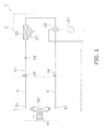
- FIG. 1 is a schematic configuration diagram of an air conditioning apparatus 1 in which an indoor unit 4 serving as a ceiling-mounted air conditioning unit pertaining to the embodiments of the present invention is employed.
- the air conditioning apparatus 1 is a split type air conditioning apparatus, mainly has an outdoor unit 2, the indoor unit 4, and a liquid refrigerant connection tube 5 and a gas refrigerant connection tube 6 that interconnect the outdoor unit 2 and the indoor unit 4, and configures a vapor compression refrigerant circuit 10.
- the outdoor unit 2 is installed outdoors or the like and mainly has a compressor 21, a four-way switching valve 22, an outdoor heat exchanger 23, an expansion valve 24, a liquid-side stop valve 25, and a gas-side stop valve 26.
- the compressor 21 is a compressor for sucking in low-pressure gas refrigerant, compressing the low-pressure gas refrigerant into high-pressure gas refrigerant, and thereafter discharging the high-pressure gas refrigerant.
- the four-way switching valve 22 is a valve for switching the direction of the flow of the refrigerant when switching between cooling and heating.
- the four-way switching valve 22 is capable of interconnecting the discharge side of the compressor 21 and the gas side of the outdoor heat exchanger 23 and also interconnecting the gas-side stop valve 26 and the suction side of the compressor 21 (refer to the solid lines of the four-way switching valve 22 in FIG. 1 ).
- the four-way switching valve 22 is capable of interconnecting the discharge side of the compressor 21 and the gas-side stop valve 26 and also interconnecting the gas side of the outdoor heat exchanger 23 and the suction side of the compressor 21 (refer to the broken lines of the four-way switching valve 22 in FIG. 1 ).
- the outdoor heat exchanger 23 is a heat exchanger that functions as a condenser of the refrigerant during cooling and functions as an evaporator of the refrigerant during heating.
- the liquid side of the outdoor heat exchanger 23 is connected to the expansion valve 24, and the gas side of the outdoor heat exchanger 23 is connected to the four-way switching valve 22.
- the expansion valve 24 is an electrical expansion valve which, during cooling, is capable of reducing the pressure of the high-pressure liquid refrigerant that has been condensed in the outdoor heat exchanger 23 before sending it to an indoor heat exchanger 42 (described later) and which, during heating, is capable of reducing the pressure of the high-pressure liquid refrigerant that has been condensed in the indoor heat exchanger 42 before sending it to the outdoor heat exchanger 23.
- the liquid-side stop valve 25 and the gas-side stop valve 26 are valves disposed in openings that connect to external devices and pipes (specifically, the liquid refrigerant connection tube 5 and the gas refrigerant connection tube 6).
- the liquid-side stop valve 25 is connected to the expansion valve 24.
- the gas-side stop valve 26 is connected to the four-way switching valve 22.
- an outdoor fan 27 for sucking outdoor air into the inside of the unit, supplying the outdoor air to the outdoor heat exchanger 23, and thereafter discharging the outdoor air to the outside of the unit is disposed in the outdoor unit 2.
- the outdoor heat exchanger 23 is a heat exchanger that uses the outdoor air as a cooling source or a heating source to condense and evaporate the refrigerant.
- the indoor unit 4 is a form of ceiling-mounted air conditioning unit called a ceiling-embedded type and has a casing 31 that stores various types of components inside.
- the casing 31 is configured from a casing body 31a and a decorative panel 32 that is placed on the underside of the casing body 31a.
- the casing body 31a is inserted and placed in an opening formed in a ceiling U of an air-conditioned room.
- the decorative panel 32 is placed in such a way as to be fitted into the opening in the ceiling U.
- FIG. 2 is an external perspective view of the indoor unit 4 serving as the ceiling-mounted air conditioning unit pertaining to the embodiments of the present invention.
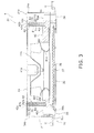
- FIG. 3 is a schematic side sectional view of the indoor unit 4 serving as the ceiling-mounted air conditioning unit pertaining to the embodiments of the present invention and is a sectional view taken along A-O-A in FIG. 4 .
- the casing body 31a is a box-like body whose undersurface is open and which has a substantially octagonal shape where long sides and short sides are alternately formed as seen in a plan view thereof.
- the casing body 31a has a top plate 33 that has a substantially octagonal shape where long sides and short sides are alternately continuously formed and a side plate 34 that extends downward from the peripheral edge portion of the top plate 33.
- FIG. 4 is a schematic plan view showing a state where the top plate 33 of the indoor unit 4 serving as the ceiling-mounted air conditioning unit pertaining to the embodiments of the present invention has been removed.
- the side plate 34 is configured from side plates 34a, 34b, 34c, and 34d that correspond to the long sides of the top plate 33 and side plates 34e, 34f, 34g, and 34h that correspond to the short sides of the top plate 33.
- the side plate 34h configures a portion penetrated by a liquid-side connecting tube 51 and a gas-side connecting tube 61 for interconnecting the indoor heat exchanger 42 and the refrigerant connection tubes 5 and 6.
- the decorative panel 32 is a plate-like body that has a substantially quadrilateral shape as seen in a plan view.
- the decorative panel 32 is mainly configured from a panel body 32a that is fixed to the lower end portion of the casing body 31a.
- the panel body 32a has a suction opening 35 that is disposed in the substantial center of the panel body 32a and sucks in the air inside the air-conditioned room and a blow-out opening 36 that is formed in such a way as to surround the periphery of the suction opening 35 as seen in a plan view and blows out the air into the air-conditioned room.
- the suction opening 35 is an opening that has a substantially quadrilateral shape.
- a suction grille 37 and a filter 38 for removing dirt and dust in the air that has been sucked in from the suction opening 35 are disposed in the suction opening 35.
- the blow-out opening 36 is an opening that has a substantially four-sided annular shape.
- Horizontal flaps 39a. 39b., 39c, and 39d that adjust the direction of the air blown out into the air-conditioned room are disposed in the blow-out opening 36 in such a way as to correspond to the sides of the quadrilateral shape of the panel body 32a.
- an indoor fan 41 serving as a centrifugal blower that sucks the air inside the air-conditioned room through the suction opening 35 in the decorative panel 32 into the inside of the casing body 31a and blows out the air through the blow-out opening 36 in the decorative panel 32 from the inside of the casing body 31a; and an indoor heat exchanger 42.
- the indoor fan 41 has a fan motor 41a that is disposed in the center of the top plate 33 of the casing body 31a and an impeller 41b that is coupled to and driven to rotate by the fan motor 41a.
- the impeller 41b is an impeller with turbo blades and can suck air into the inside of the impeller 41b from below and blow out the air toward the outer peripheral side of the impeller 41b as seen in a plan view.
- the indoor heat exchanger 42 is a fin-and-tube heat exchanger placed on the outer peripheral side of the indoor fan 41 as seen in a plan view. More specifically, the indoor heat exchanger 42 is bent and placed in such a way as to surround the periphery of the indoor fan 41 and is a fin-and-tube heat exchanger called a cross-fin type that has numerous heat transfer fins placed a predetermined interval apart from each other and plural heat transfer tubes disposed in a state where they penetrate these heat transfer fins in their plate thickness direction.
- the liquid side of the indoor heat exchanger 42 is connected to the liquid refrigerant connection tube 5 via the liquid-side connecting tube 51, and the gas side of the indoor heat exchanger 42 is connected to the gas refrigerant connection tube 6 via the gas-side connecting tube 61.
- the indoor heat exchanger 42 functions as an evaporator of the refrigerant during cooling and as a condenser of the refrigerant during heating. Because of this, the indoor heat exchanger 42 can perform heat exchange with the air that has been blown out from the indoor fan 41, cool the air during cooling, and heat the air during heating.
- a drain pan 40 for receiving drain water produced as a result of moisture in the air being condensed in the indoor heat exchanger 42 is placed on the underside of the indoor heat exchanger 42.
- the drain pan 40 is attached to the lower portion of the casing body 31a.
- Blow-out holes 40a, 40b, 40c, 40d, 40e, 40f, and 40g, a suction hole 40h, and a drain water receiving groove 40i are formed in the drain pan 40.
- the blow-out holes 40a, 40b, 40c, 40d, 40e, 40f, and 40g are formed in such a way as to be communicated with the blow-out opening 36 in the decorative panel 32.
- the suction hole 40h is formed in such a way as to be communicated with the suction opening 35 in the decorative panel 32.
- the drain water receiving groove 40i is formed on the underside of the indoor heat exchanger 42. Further, a bellmouth 41c for guiding the air sucked in from the suction opening 35 to the impeller 41b of the indoor fan 41 is placed in the suction hole 40h in the drain pan 40.
- the four-way switching valve 22 is in the state indicated by the solid lines in FIG. 1 . Further, the liquid-side stop valve 25 and the gas-side stop valve 26 are placed in an open state, and the opening degree of the expansion valve 24 is adjusted in such a way that the expansion valve 24 reduces the pressure of the refrigerant.
- low-pressure gas refrigerant is sucked into the compressor 21 and is compressed and becomes high-pressure gas refrigerant in the compressor 21, and the high-pressure gas refrigerant is discharged from the compressor 21.
- This high-pressure gas refrigerant is sent through the four-way switching valve 22 to the outdoor heat exchanger 23 and performs heat exchange with the outdoor air, condenses, and becomes high-pressure liquid refrigerant in the outdoor heat exchanger 23.
- This high-pressure liquid refrigerant is sent to the expansion valve 24 and has its pressure reduced and becomes low-pressure refrigerant in a gas-liquid two-phase state in the expansion valve 24.
- This low-pressure refrigerant in a gas-liquid two-phase state is sent through the liquid-side stop valve 25, the liquid refrigerant connection tube 5, and the liquid-side connecting tube 51 to the indoor heat exchanger 42 and performs heat exchange with the air blown out from the indoor fan 41, evaporates, and becomes low-pressure gas refrigerant in the indoor heat exchanger 42.
- This low-pressure gas refrigerant is sent through the gas-side connecting tube 61, the gas refrigerant connection tube 6, the gas-side stop valve 26, and the four-way switching valve 22 back to the compressor 21.
- the four-way switching valve 22 is in the state indicated by the broken lines in FIG. 1 . Further, the liquid-side stop valve 25 and the gas-side stop valve 26 are placed in an open state, and the opening degree of the expansion valve 24 is adjusted in such a way that the expansion valve 24 reduces the pressure of the refrigerant.
- This high-pressure liquid refrigerant is sent through the liquid-side connecting tube 51, the liquid refrigerant connection tube 5, and the liquid-side stop valve 25 to the expansion valve 24 and has its pressure reduced and becomes low-pressure refrigerant in a gas-liquid two-phase state in the expansion valve 24.
- This low-pressure refrigerant in a gas-liquid two-phase state is sent to the outdoor heat exchanger 23 and performs heat exchange with the outdoor air, evaporates, and becomes low-pressure gas refrigerant in the outdoor heat exchanger 23.
- This low-pressure gas refrigerant is sent through the four-way switching valve 22 back to the compressor 21.
- the indoor heat exchanger 42 pertaining to a first embodiment employs a structure where plural heat transfer tubes 71, 72, and 73 inside of which flows the refrigerant are placed in multiple stages in a vertical direction and, in order to increase performance, are arranged in three rows in the flow direction of the air blown out from the indoor fan 41 serving as the centrifugal blower.
- the indoor heat exchanger 42 mainly has a first heat exchange section 42a, a second heat exchange section 42b, and a third heat exchange section 42c.
- FIG. 5 is a view showing refrigerant paths in the indoor heat exchanger 42 in the indoor unit 4 serving as the ceiling-mounted air conditioning unit pertaining to the first embodiment.
- a state where one lengthwise direction end side of the indoor heat exchanger 42 is seen from the direction of arrow B is indicated by the solid lines and, for the convenience of illustration, a state where the other lengthwise direction end side of the indoor heat exchanger 42 is seen from the direction of arrow C is illustrated by broken lines superimposed on the one end side of the indoor heat exchanger 42.
- the first heat exchange section 42a configures a row on the most upwind side (hereinafter called a first row) of the indoor heat exchanger 42 in the flow direction of the air.
- the first heat exchange section 42a has numerous first heat transfer fins 81 placed a predetermined interval apart from each other and plural (here, ten) first heat transfer tubes 71 disposed in a state where they penetrate these first heat transfer fins 81 in their plate thickness direction.
- the first heat transfer fins 81 are plate-like members that are long and narrow in the vertical direction.
- the first heat transfer tubes 71 are tube members extending in the lengthwise direction of the indoor heat exchanger 42 and are placed in ten stages in the vertical direction.
- the second heat exchange section 42b configures a second row of the indoor heat exchanger 42 in the flow direction of the air.
- the second heat exchange section 42b has numerous second heat transfer fins 82 placed a predetermined interval apart from each other and plural (here, ten) second heat transfer tubes 72 disposed in a state where they penetrate these second heat transfer fins 82 in their plate thickness direction.
- the second heat transfer fins 82 are plate-like members that are long and narrow in the vertical direction.
- the second heat transfer tubes 72 are tube members extending in the lengthwise direction of the indoor heat exchanger 42 and are placed in ten stages in the vertical direction.
- the third heat exchange section 42c configures a row on the most downwind side (hereinafter called a third row) of the indoor heat exchanger 42 in the flow direction of the air.
- the third heat exchange section 42c has numerous third heat transfer fins 83 placed a predetermined interval apart from each other and plural (here, ten) third heat transfer tubes 73 disposed in a state where they penetrate these third heat transfer fins 83 in their plate thickness direction.
- the third heat transfer fins 83 are plate-like members that are long and narrow in the vertical direction.
- the third heat transfer tubes 73 are tube members extending in the lengthwise direction of the indoor heat exchanger 42 and are placed in ten stages in the vertical direction.
- the indoor heat exchanger 42 is configured by stacking together these heat exchange sections 42a, 42b, and 42c in the flow direction of the air and bending them in such a way as to surround the periphery of the indoor fan 41 as seen in a plan view.
- the heat transfer tubes 71, 72, and 73 are staggered with respect to the heat transfer fins 81, 82, and 83 overall.
- a flow divider 52 that becomes a refrigerant inlet of the indoor heat exchanger 42 in a case where the indoor heat exchanger 42 functions as an evaporator of the refrigerant during cooling and becomes a refrigerant outlet of the indoor heat exchanger 42 in a case where the indoor heat exchanger 42 functions as a condenser of the refrigerant during heating is connected to the liquid-side connecting tube 51.
- Plural (in FIG. 5 , only three are illustrated) liquid refrigerant tubes 91 connected to the first heat transfer tubes 71 of the indoor heat exchanger 42 on the one lengthwise direction end side of the indoor heat exchanger 42 are connected to the flow divider 52.
- the liquid refrigerant tubes 91 comprise capillary tubes.
- a header 62 that becomes a refrigerant outlet of the indoor heat exchanger 42 in a case where the indoor heat exchanger 42 functions as an evaporator of the refrigerant during cooling and becomes a refrigerant inlet of the indoor heat exchanger 42 in a case where the indoor heat exchanger 42 functions as a condenser of the refrigerant during heating is connected to the gas-side connecting tube 61.
- the indoor heat exchanger 42 has plural stages (in FIG. 5 , only three are illustrated) of refrigerant paths that are configured as a result of the heat transfer tubes 71, 72, and 73 in two stages each in three rows being interconnected.
- Each of the refrigerant paths has first heat transfer tubes 71a which, of the first heat transfer tubes 71, are connected to the liquid refrigerant tubes 91.
- the first heat transfer tubes 71a are connected via U-shaped portions 71c to first heat transfer tubes 71b that are the first heat transfer tubes 71 placed one stage on the upper sides of the first heat transfer tubes 71a on the other lengthwise direction end side of the indoor heat exchanger 42. As shown in FIG.
- each of the U-shaped portions 71c is a U-shaped tube portion joining together the heat transfer tubes placed in the same row (here, the first heat transfer tubes 71).
- the first heat transfer tubes 71b are connected to inter-row branching portions 71d on the one lengthwise direction end side of the indoor heat exchanger 42.
- the inter-row branching portions 71d are portions that cause the refrigerant that has passed through the first heat transfer tubes 71b during cooling to branch into two flows.
- One of the branches of each of the inter-row branching portions 71d is connected, on the one lengthwise direction end side of the indoor heat exchanger 42, to second heat transfer tubes 72a which, of the second heat transfer tubes 72, are the second heat transfer tubes 72 placed on the upper sides of the first heat transfer tubes 71b.
- the other of the branches of each of the inter-row branching portions 71d is connected, on the one lengthwise direction end side of the indoor heat exchanger 42, to third heat transfer tubes 73a which, of the third heat transfer tubes 73. are the third heat transfer tubes 73 placed on the lower sides of the second heat transfer tubes 72a. As shown in FIG.
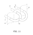
- each of the inter-row branching portions 71d is a tube portion having a shape where the end portion of a U-shaped tube portion extending from the first heat transfer tube 71 is joined together with the middle portion of a U-shaped tube portion joining together the second heat transfer tube 72 and the third heat transfer tube 73.
- the position at which the U-shaped tube portion extending from the first heat transfer tube 71 and the U-shaped tube portion joining together the second heat transfer tube 72 and the third heat transfer tube 73 are interconnected is set in such a way that the flow path length from the second heat transfer tube 72 and the flow path length from the third heat transfer tube 73 become the same.
- the second heat transfer tubes 72a are connected, on the other lengthwise direction end side of the indoor heat exchanger 42, via U-shaped portions 72c (see FIG. 6 ) to second heat transfer tubes 72b that are the second heat transfer tubes 72 placed one stage on the lower sides of the second heat transfer tubes 72a.
- the third heat transfer tubes 73a are connected, on the other lengthwise direction end side of the indoor heat exchanger 42, via U-shaped portions 73c (see FIG. 6 ) to third heat transfer tubes 73b that are the third heat transfer tubes 73 placed one stage on the lower sides of the third heat transfer tube 73a.
- the second heat transfer tubes 72b are connected to the second row-side gas refrigerant tubes 92 on the one lengthwise direction end side of the indoor heat exchanger 42.
- the third heat transfer tubes 73b are connected to the third row-side gas refrigerant tubes 93 on the one lengthwise direction end side of the indoor heat exchanger 42.
- the heat transfer tubes 71a and 71b are configured as single heat transfer tubes bent in the shape of hairpins including the U-shaped portions 71c.
- the heat transfer tubes 72a and 72b are configured as single heat transfer tubes bent in the shape of hairpins including the U-shape portions 72c.
- the heat transfer tubes 73a and 73b are configured as single heat transfer tubes bent in the shape of hairpins including the U-shaped portions 73c.
- the refrigerant that has traveled through the liquid-side connecting tube 51 and the flow divider 52 serving as the refrigerant inlet during cooling and has passed through the liquid refrigerant tubes 91 is sent to the first heat transfer tubes 71a (first upstream-side heat transfer tubes) that are one of the first heat transfer tubes 71 in the first row.
- the refrigerant that has been sent to the first heat transfer tubes 71a passes through the first heat transfer tubes 71a and thereafter further passes through the first heat transfer tubes 71b (first downstream-side heat transfer tubes) that are the first heat transfer tubes 71 in the first row apart from the first heat transfer tubes 71 a.
- the refrigerant that has passed through the first heat transfer tubes 71b is caused by the inter-row branching portions 71d to branch into the second heat transfer tubes 72a (second upstream-side heat transfer tubes) that is one of the heat transfer tubes 72 in the second row and the third heat transfer tubes 73a (third upstream-side heat transfer tubes) that is one of the third heat transfer tubes 73 in the third row.
- the refrigerant that has been sent to the second heat transfer tubes 72a passes through the second heat transfer tubes 72a, thereafter further passes through the second heat transfer tubes 72b (second downstream-side heat transfer tubes) that are the second heat transfer tubes 72 in the second row apart from the second heat transfer tubes 72a, and is sent from the outlets of the second heat transfer tubes 72b to the second row-side gas refrigerant tubes 92.
- the refrigerant that has been sent to the third heat transfer tubes 73a passes through the third heat transfer tubes 73a, thereafter further passes through the third heat transfer tubes 73b (third downstream-side heat transfer tubes) that are the third heat transfer tubes 73 in the third row apart from the third heat transfer tubes 73a, and is sent from the outlets of the third heat transfer tubes 73b to the third row-side gas refrigerant tubes 93.
- the refrigerant that has passed through the second row-side gas refrigerant tubes 92 and the third row-side gas refrigerant tubes 93 is sent to the header 62 and the gas-side connecting tube 61 serving as the refrigerant outlet during cooling.
- the refrigerant that has traveled through the gas-side connecting tube 61 and the header 62 serving as the refrigerant inlet during heating and has passed through the second row-side gas refrigerant tubes 92 and the third row-side gas refrigerant tubes 93 is sent to the second heat transfer tubes 72b that are one of the second heat transfer tubes 72 in the second row and the third heat transfer tubes 73b that are one of the third heat transfer tubes 73 in the third row.
- the refrigerant that has been sent to the second heat transfer tubes 72b passes through the second heat transfer tubes 72b and thereafter further passes through the second heat transfer tubes 72a that are the second heat transfer tubes 72 in the second row apart from the second heat transfer tubes 72b.
- the refrigerant that has been sent to the third heat transfer tubes 73b passes through the third heat transfer tubes 73b and thereafter further passes through the third heat transfer tubes 73a that are the third heat transfer tubes 73 in the third row apart from the third heat transfer tubes 73b.
- the refrigerant that has passed through the second heat transfer tubes 72a and the refrigerant that has passed through the third heat transfer tubes 73a are caused by the inter-row branching portions 71d to merge together in the outlets of the second heat transfer tubes 72a and the outlets of the third heat transfer tubes 73 a and are sent to the first heat transfer tubes 71b that are one of the first heat transfer tubes 71 in the first row. Then, the refrigerant that has been sent to the first heat transfer tubes 71b passes through the first heat transfer tubes 71 b, thereafter further passes through the first heat transfer tubes 71a that are the first heat transfer tubes 71 in the first row apart from the first heat transfer tubes 71b, and is sent to the liquid refrigerant tubes 91. The refrigerant that has passed through the liquid refrigerant tubes 91 is sent to the flow divider 52 and the liquid-side connecting tube 51 serving as the refrigerant outlet during heating.
- the indoor unit 4 serving as the ceiling-mounted air conditioning unit having the indoor heat exchanger 42 of the present embodiment has the following characteristics.
- the indoor heat exchanger 42 of the present embodiment has a structure where the plural liquid refrigerant tubes 91 connected to the refrigerant inlet of the indoor heat exchanger 42 in a case where the indoor heat exchanger 42 functions as an evaporator of the refrigerant during cooling are connected to the heat transfer tubes 71 in the first row that is the row on the most upwind side in the flow direction of the air. Further, this indoor heat exchanger 42 has a structure where the second row-side gas refrigerant tubes 92 that are some of the plural gas refrigerant tubes 92 and 93 connected to the refrigerant outlet of the indoor heat exchanger 42 during cooling are connected to the heat transfer tubes 72 in the second row in the flow direction of the air.
- this indoor heat exchanger 42 has a structure where the third row-side gas refrigerant tubes 93 that are the rest of the plural gas refrigerant tubes 92 and 93 are connected to the heat transfer tubes 73 in the third row that is the row on the most downwind side in the flow direction of the air.
- the indoor unit 4 of the present embodiment during cooling, some of the refrigerant inflowing from the refrigerant inlet during cooling of the indoor heat exchanger 42 is sent to the second row-side gas refrigerant tubes 92 immediately after performing heat exchange with the air crossing the heat transfer tubes 72 in the second row whose temperature is higher than that of the air crossing the heat transfer tubes 73 in the third row. Further, in this indoor unit 4, during cooling, the rest of the refrigerant inflowing from the refrigerant inlet during cooling of the indoor heat exchanger 42 is sent to the third row-side gas refrigerant tubes 93 immediately after performing heat exchange with the air crossing the heat transfer tubes 73 in the third row.
- the refrigerant that has passed through the second row-side gas refrigerant tubes 92 and the refrigerant that has passed through the third row-side gas refrigerant tubes 93 merge together and exit from the refrigerant outlet during cooling of the indoor heat exchanger 42.
- the degree of superheat of the refrigerant immediately after performing heat exchange with the air crossing the heat transfer tubes 72 in the second row easily becomes larger than the degree of superheat of the refrigerant immediately after performing heat exchange with the air crossing the heat transfer tubes 73 in the third row because it is affected by the temperature of the air crossing the heat transfer tubes 72 in the second row.
- this indoor unit 4 it becomes easier for the degree of superheat of the refrigerant exiting from the refrigerant outlet during cooling of the indoor heat exchanger 42 to become larger compared to the case of employing a structure where all of the gas refi-igerant tubes 92 and 93 are connected to the heat transfer tubes 73 in the third row, and the heat exchange efficiency during cooling can be improved.
- this indoor unit 4 it can be made more difficult for the degree of subcooling in the refrigerant outlet during heating of the indoor heat exchanger 42 to become smaller and it can also be made easier for the degree of superheat of the refrigerant exiting from the refrigerant outlet during cooling of the indoor heat exchanger 42 to become larger, and the heat exchange efficiency of the indoor heat exchanger 42 during cooling can be improved while suppressing a drop in the heat exchange efficiency of the indoor heat exchanger 42 during heating.
- the liquid refrigerant tubes 91, the second row-side gas refrigerant tubes 92, and the third row-side gas refrigerant tubes 93 are connected to the lengthwise direction single ends of the corresponding heat transfer tubes 71, 72, and 73.
- the work of connecting the liquid refrigerant tubes 91, the second row-side gas refrigerant tubes 92, and the third row-side gas refrigerant tubes 93 to the heat transfer tubes 71, 72, and 73 can be consolidated and performed on the one lengthwise direction end side of the indoor heat exchanger 42, so the assemblability of the indoor heat exchanger 42 improves.
- the refrigerant flowing through the heat transfer tubes 71, 72, and 73 in each row flows in such a way that, after heading from the one lengthwise direction end of the indoor heat exchanger 42 to the other end, it turns back from the other lengthwise direction end to the one end.
- the liquid refrigerant tubes 91, the second row-side gas refrigerant tubes 92, and the third row-side gas refrigerant tubes 93 consolidated on the one lengthwise direction end side of the indoor heat exchanger 42, but the inter-row branching portions 71d also become placed on the one lengthwise direction end side of the indoor heat exchanger 42.
- the work of connecting the liquid refrigerant tubes 91, the second row-side gas refrigerant tubes 92, the third row-side gas refrigerant tubes 93, and the inter-row branching portions 71d to the heat transfer tubes 71, 72, and 73 can be consolidated and performed on the one lengthwise direction end side of the indoor heat exchanger 42, so the assemblability of the indoor heat exchanger 42 further improves.
- the indoor heat exchanger 42 of the present embodiment has the inter-row branching portions 71d that cause the refrigerant that has been sent to the outlets of the heat transfer tubes 71 in the first row during cooling to branch into the heat transfer tubes 72 in the second row and the heat transfer tubes 73 in the third row. Additionally, the outlets of the heat transfer tubes 72 in the second row in a case where the indoor heat exchanger 42 functions as an evaporator of the refrigerant during cooling are connected to the second rour-side gas refrigerant tubes 92. Further, the outlets of the heat transfer tubes 73 in the third row in a case where the indoor heat exchanger 42 functions as an evaporator of the refrigerant during cooling are connected to the third row-side gas refrigerant tubes 93.
- the refrigerant that has become gas-rich because of heat exchange with the air in the heat transfer tubes 71 in the first row is caused to branch into and is sent through the heat transfer tubes 72 in the second row and the heat transfer tubes 73 in the third row, so an increase in the flow speed of the refrigerant that has become gas-rich can be suppressed.
- the refrigerant that has become liquid-rich because of heat exchange with the air in the heat transfer tubes 72 in the second row and the refrigerant that has become liquid-rich because of heat exchange with the air in the heat transfer tubes 73 in the third row are caused to merge together and become sent to the heat transfer tubes 71 in the first row, so the flow speed of the refrigerant that has become liquid-rich can be increased to thereby increase the heat transfer coefficient in the heat transfer tubes 71 in the first row.
- an increase in pressure drop can be suppressed as a result of the intcr-row branching portions 71d causing the flow of the refrigerant to branch, so the heat exchange efficiency of the indoor heat exchanger 42 during cooling can be further improved.
- an increase in the flow speed of the refrigerant in the heat transfer tubes 72 in the second row and the heat transfer tubes 73 in the third row through which flows the gas-rich refrigerant whose effect with respect to pressure drop is large is suppressed, so the heat exchange efficiency of the indoor heat exchanger 42 during cooling can be effectively improved.
- the heat transfer coefficient is increased by increasing the flow speed of the refrigerant in the heat transfer tubes 71 in the first row through which flows the liquid-rich refrigerant whose effect with respect to pressure drop is small, so it becomes easier for the degree of subcooling in the refrigerant outlet during heating of the indoor heat exchanger 42 to become larger, and a drop in the heat exchange efficiency during heating can be further suppressed.
- the first heat transfer tubes 71b (first downstream-side heat transfer tubes) connected to the inter-row branching portions 71d are placed one stage on the upper sides of the first heat transfer tubes 71a (first upstream-side heat transfer tubes), which are connected to the upstream sides of the first heat transfer tubes 71b during cooling and are connected to the liquid refrigerant tubes 91.
- the indoor unit 4 of the present embodiment it becomes easier for the degree of subcooling in the refrigerant outlet during heating of the indoor heat exchanger 42 to become larger, and a drop in the heat exchange efficiency during heating can be further suppressed.
- the inter-row branching portions 71d are connected, on the one lengthwise direction end side of the indoor heat exchanger 42, to the second heat transfer tubes 72a (second upstream-side heat transfer tubes) and the third heat transfer tubes 73a (third upstream-side heat transfer tubes) placed on the lower sides of the second heat transfer tubes 72a.
- the second heat transfer tubes 72a (second upstream-side heat transfer tubes) to which the inter-row branching portions 71d are connected are placed on the lower sides of the third heat transfer tubes 73a (third upstream-side heat transfer tubes) to which the inter-row branching portions 71d are connected.
- the inter-row branching portions 71d are formed in such a way that the flow path length from the outlets of the first heat transfer tubes 71b (first downstream-side heat transfer tubes) to the inlets of the second heat transfer tubes 72a (second upstream-side heat transfer tubes) and the flow path length from the outlets of the first heat transfer tubes 71b to the inlets of the third heat transfer tubes 73a (third upstream-side heat transfer tubes) in a case where the indoor heat exchanger 42 functions as an evaporator of the refrigerant during cooling become the same.
- the inter-row branching portions 71d are formed in such a way that the flow path length from the outlets of the first heat transfer tubes 71b (first downstream-side heat transfer tubes) to the inlets of the third heat transfer tubes 73a (third upstream-side heat transfer tubes) becomes longer than the flow path length from the outlets of the first heat transfer tubes 71b (first downstream-side heat transfer tubes) to the inlets of the second heat transfer tubes 72a (second upstream-side heat transfer tubes) in a case where the indoor heat exchanger 42 functions as an evaporator of the refrigerant during cooling.
- each of the inter-row branching portions 71d is made into a tube portion having a shape where the end portion of a U-shaped tube portion extending from the third heat transfer tube 73 is joined together with the middle portion of a U-shaped tube portion joining together the first heat transfer tube 71 and the second heat transfer tube 72.
- modification 1 and the characteristics of modification 2 may also be combined and applied with respect to the indoor heat exchanger 42 configuring the indoor unit 4 described above (see FIG. 5 ).
- the second heat transfer tubes 72a second upstream-side heat transfer tubes
- the third heat transfer tubes 73a third upstream-side heat transfer tubes
- the inter-row branching portions 71d are formed in such a way that the flow path length from the outlets of the first heat transfer tubes 71b (first downstream-side heat transfer tubes) to the inlets of the third heat transfer tubes 73a (third upstream-side heat transfer tubes) becomes longer than the flow path length from the outlets of the first heat transfer tubes 71b (first downstream-side heat transfer tubes) to the inlets of the second heat transfer tubes 72a (second upstream-side heat transfer tubes) in a case where the indoor heat exchanger 42 functions as an evaporator of the refrigerant during cooling.
- the second heat transfer tubes 72b (second downstream-side heat transfer tubes) connected to the second row-side gas refrigerant tubes 92 are placed one stage on the lower sides of the second heat transfer tubes 72a (second upstream-side heat transfer tubes) connected to the upstream sides of the second heat transfer tubes 72b during cooling. Further, in the indoor heat exchanger 42 configuring the indoor unit 4 described above (see FIG. 5 ), the second heat transfer tubes 72b (second downstream-side heat transfer tubes) connected to the second row-side gas refrigerant tubes 92 are placed one stage on the lower sides of the second heat transfer tubes 72a (second upstream-side heat transfer tubes) connected to the upstream sides of the second heat transfer tubes 72b during cooling. Further, in the indoor heat exchanger 42 configuring the indoor unit 4 described above (see FIG.
- the third heat transfer tubes 73b (third downstream-side heat transfer tubes) connected to the third row-side gas refrigerant tubes 93 are placed one stage on the lower sides of the third heat transfer tubes 73a (third upstream-side heat transfer tubes) connected to the upstream sides of the third heat transfer tubes 73b during cooling.
- the second heat transfer tubes 72b (second downstream-side heat transfer tubes) connected to the second row-side gas refrigerant tubes 92 are placed one stage on the upper sides of the second heat transfer tubes 72a (second upstream-side heat transfer tubes) connected to the upstream sides of the second heat transfer tubes 72b during cooling.
- the third heat transfer tubes 73b (third downstream-side heat transfer tubes) connected to the third row-side gas refrigerant tubes 93 are placed one stage on the upper sides of the third heat transfer tubes 73a (third upstream-side heat transfer tubes) connected to the upstream sides of the third heat transfer tubes 73b during cooling.
- the second heat transfer tubes 72b are placed on the upper sides of the second heat transfer tubes 72a, and the third heat transfer tubes 73b are placed on the upper sides of the third heat transfer tubes 73a, but the modification may also be configured in such a way as to just place the second heat transfer tubes 72b on the upper sides of the second heat transfer tubes 72a or so as to just place the third heat transfer tubes 73b on the upper sides of the third heat transfer tubes 73a.
- the first heat transfer tubes 71b (first downstrcaln-sidc heat transfer tubes) connected to the inter-row branching portions 71d are placed one stage on the lower sides of the first heat transfer tubes 71a (first upstream-side heat transfer tubes), which are connected to the upstream sides of the first heat transfer tubes 71b during cooling and are connected to the liquid refrigerant tubes 91.
- the first heat transfer tubes 71b (first downstream-side heat transfer tubes) connected to the inter-row branching portions 71d are placed one stage on the upper sides of the first heat transfer tubes 71a (first upstream-side heat transfer tubes), which are connected to the upstream sides of the first heat transfer tubes 71b during cooling and are connected to the liquid refrigerant tubes 91.
- this indoor heat exchanger 42 like in the indoor heat exchanger 42 configuring the indoor unit 4 described above (see FIG. 5 ), during heating, the refrigerant, passing through the first heat transfer tubes 71a and 71b flows in such a way as to descend toward the liquid refrigerant tubes 91.
- the inter-row branching portions 71d are connected, on the one lengthwise direction end side of the indoor heat exchanger 42, to the second heat transfer tubes 72a (second upstream-side heat transfer tubes) and the third heat transfer tubes 73a (third upstream-side heat transfer tubes) placed on the lower sides of the second heat transfer tubes 72a.
- the second heat transfer tubes 72a second upstream-side heat transfer tubes
- the third heat transfer tubes 73a third upstream-side heat transfer tubes
- the inter-row branching portions 71d are formed in such a way that the flow path length from the outlets of the first heat transfer tubes 71b (first downstream-side heat transfer tubes) to the inlets of the second heat transfer tubes 72a (second upstream-side heat transfer tubes) and the flow path length from the outlets of the first heat transfer tubes 71b to the inlets of the third heat transfer tubes 73a (third upstream-side heat transfer tubes) in a case where the indoor heat exchanger 42 functions as an evaporator of the refrigerant during cooling became the same.
- the inter-row branching portions 71d are formed in such a way that the flow path length from the outlets of the first heat transfer tubes 71b (first downstream-side heat transfer tubes) to the inlets of the third heat transfer tubes 73a (third upstream-side heat transfer tubes) becomes longer than the flow path length from the outlets of the first heat transfer tubes 71b (first downstream-side heat transfer tubes) to the inlets of the second heat transfer tubes 72a (second upstream-side heat transfer tubes) in a case where the indoor heat exchanger 42 functions as an evaporator of the refrigerant during cooling.
- each of the inter-row branching portions 71d is made into a tube portion having a shape where the end portion of a U-shaped tube portion extending from the third heat transfer tube 73 is joined together with the middle portion of a U-shaped tube portion joining together the first heat transfer tube 71 and the second heat transfer tube 72.
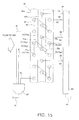
- the characteristics of modification 6 and the characteristics of modification 7 may also be combined and applied with respect to the indoor heat exchanger 42 configuring the indoor unit 4 pertaining to modification 5 (see FIG. 15 ).
- the second heat transfer tubes 72a (second upstream-side heat transfer tubes) to which the inter-row branching portions 71d are connected are placed on the lower sides of the third heat transfer tubes 73 a (third upstream-side heat transfer tubes) to which the inter-row branching portions 71d are connected.
- the inter-row branching portions 7 1 d are formed in such a way that the flow path length from the outlets of the first heat transfer tubes 71b (first downstream-side heat transfer tubes) to the inlets of the third heat transfer tubes 73a (third upstream-side heat transfer tubes) becomes longer than the flow path length from the outlets of the first heat transfer tubes 71b (first downstream-side heat transfer tubes) to the inlets of the second heat transfer tubes 72a (second upstream-side heat transfer tubes) in a case where the indoor heat exchanger 42 functions as an evaporator of the refrigerant during cooling.
- the indoor heat exchanger 42 configuring the indoor unit 4 described above has plural stages (in FIG. 5 , only three are illustrated) of refrigerant paths that are configured as a result of the heat transfer tubes 71, 72, and 73 in two stages each in three rows being interconnected; moreover, as for these refrigerant paths, the paths that join together the liquid refrigerant tubes 91 and the gas refrigerant tubes 92 and 93 are the same.
- the outlets of the second heat transfer tubes 72b (second downstream-side heat transfer tubes) connected to the second row-side gas refrigerant tubes 92 and the outlets of the third heat transfer tubes 73b (third downstream-side heat transfer tubes) connected to the third row-side gas refrigerant tubes 93 in a case where the indoor heat exchanger 42 functions as an evaporator of the refrigerant during cooling are placed away from the outlets of the other second heat transfer tubes 72b (second downstream-side heat transfer tubes) and the outlets of the other third heat transfer tubes 73b (third downstream-side heat transfer tubes) configuring the refrigerant paths placed on the upper sides or the lower sides.
- the inlets of the first heat transfer tubes 71a (first upstream-side heat transfer tubes) connected to the liquid refrigerant tubes 91 in a case where the indoor heat exchanger 42 functions as an evaporator of the refrigerant during cooling are placed away from the inlets of the other first heat transfer tubes 71a (first upstream-side heat transfer tubes) placed on the upper sides or the lower sides.
- the outlets of the second heat transfer tubes 72b (second downstream-side heat transfer tubes) and the outlets of the third heat transfer tubes 73b (third downstream-side heat transfer tubes) in a case where the indoor heat exchanger 42 functions as an evaporator of the refrigerant during cooling are placed in such a way as to be adjacent to the outlets of other second heat transfer tubes 72f (second downstream-side heat transfer tubes) and the outlets of other third heat transfer tubes 73f (third downstream-side heat transfer tubes) placed on the upper sides or the lower sides.
- the inlets of the first heat transfer tubes 71a (first upstream-side heat transfer tubes) in a case where the indoor heat exchanger 42 functions as an evaporator of the refrigerant during cooling are placed in such a way as to be adjacent to the inlets of other first heat transfer tubes 71e (first upstream-side heat transfer tubes) placed on the upper sides or the lower sides.
- the indoor heat exchanger 42 of the present modification has plural stages (in FIG. 23 , only three are illustrated) where first refrigerant paths that are configured as a result of heat transfer tubes in two stages each in three rows being interconnected and second refrigerant paths that are configured as a result of other heat transfer tubes in two stages each in three rows being interconnected alternate.
- the first refrigerant paths here are the same as the refrigerant paths configuring the indoor heat exchanger 42 of modification 6 (see FIG. 17 and FIG. 18 ).
- the second refrigerant paths have the first heat transfer tubes 71e which, of the first heat transfer tubes 71, are connected to the liquid refrigerant tubes 91 and placed one stage on the lower sides of the first heat transfer tubes 71a configuring the first refrigerant paths.
- the first heat transfer tubes 71e are connected, on the other lengthwise direction end side of the indoor heat exchanger 42, via the U-shaped portions 71c (see FIG. 6 ) to first heat transfer tubes 71f that are the first heat transfer tubes 71 placed one stage on the lower sides of the first heat transfer tubes 71e.
- the first heat transfer tubes 71f are connected to the inter-row branching portions 71d on the one lengthwise direction end side of the indoor heat exchanger 42.
- the inter-row branching portions 71d are portions that cause the refrigerant that has passed through the first heat transfer tubes 71f during cooling to branch into two flows.
- One of the branches of each of the inter-row branching portions 71d is connected, on the one lengthwise direction end side of the indoor heat exchanger 42, to the second heat transfer tubes 72e which, of the second heat transfer tubes 72, are the second heat transfer tubes 72 placed on the upper sides of the first heat transfer tubes 71f.
- each of the inter-row branching portions 71d is connected, on the one lengthwise direction end side of the indoor heat exchanger 42, to the third heat transfer tubes 73e which, of the third heat transfer tubes 73, are the third heat transfer tubes 73 placed on the upper sides of the second heat transfer tubes 72e.
- each of the inter-row branching portions 71d is a tube portion having a shape where the end portion af a U-shaped tube portion extending from the first heat transfer tube 71 is joined together with the middle portion of a U-shaped tube portion joining together the second heat transfer tube 72 and the third heat transfer tube 73.
- the position at which the U-shaped tube portion extending from the first heat transfer tube 71 and the U-shaped tube portion jointing together the second heat transfer tube 72 and the third heat transfer tube 73 are interconnected is set in such a way that the flow path length from the second heat transfer tube 72 and the flow path length from the third heat transfer tube 73 become the same.
- the second heat transfer tubes 72e are connected, on the other lengthwise direction end side of the indoor heat exchanger 42, via the U-shaped portions 72c (see FIG. 6 ) to the second heat transfer tubes 72f that are the second heat transfer tubes 72 placed one stage on the lower sides of the second heat transfer tubes 72e and placed one stage on the upper sides of the second heat transfer tubes 72b configuring the first refrigerant paths.
- the third heat transfer tubes 73e are connected, on the other lengthwise direction end side of the indoor heat exchanger 42, via the U-shaped portions 73c (see FIG. 6 ) to the third heat transfer tubes 73f that are the third heat transfer tubes 73 placed one stage on the lower sides of the third heat transfer tubes 73e and placed one stage on the upper sides of the third heat transfer tubes 73b configuring the first refrigerant paths.
- the second heat transfer tubes 72f are connected to the second row-side gas refrigerant tubes 92.
- the third heat transfer tubes 73b are connected to the third row-side gas refrigerant tubes 93.
- the heat transfer tubes 71e and 71f are configured as single heat transfer tubes bent in the shape of hairpins including the U-shaped portions 71c.
- heat transfer tubes 72e and 72f are configured as single heat transfer tubes bent in the shape of hairpins including the U-shaped portions 72c.
- heat transfer tubes 73e and 73f are configured as single heat transfer tubes bent in the shape of hairpins including the U-shaped portions 73c.
- the second heat transfer tubes 72b and 72f (second downstream-side heat transfer tubes) and the third heat transfer tubes 73b and 73f (third downstream-side heat transfer tubes) whose temperature becomes higher become placed together on the heat transfer fins 81, 82, and 83, and the first heat transfer tubes 71a and 71e (first upstream-side heat transfer tubes) whose temperature becomes lower become placed together on the heat transfer fins 81, 82, and 83.
- An indoor heat exchanger 42 pertaining to the present embodiment employs a structure where, like the indoor heat exchanger 42 pertaining to the first embodiment and its modifications, as shown in FIG. 3 and FIG. 4 , the plural heat transfer tubes 71, 72, and 73 inside of which flows the refrigerant are placed in multiple stages in the vertical direction and, in order to increase performance, are arranged in three rows in the flow direction of the air blown out from the indoor fan. 41 serving as the centrifugal blower.
- the configurations of the liquid refrigerant tubes 91, the gas refrigerant tubes 92 and 93, and the refrigerant paths in the indoor heat exchanger 42 pertaining to the present embodiment differ from those in the indoor heat exchanger 42 pertaining to the first embodiment and its modifications, but the other configurations are the same as those in the indoor heat exchanger 42 pertaining to the first embodiment and its modifications, so description is omitted here.
- a flow divider 52 that becomes a refrigerant inlet of the indoor heat exchanger 42 in a case where the indoor heat exchanger 42 functions as an evaporator of the refrigerant during cooling and becomes a refrigerant outlet of the indoor heat exchanger 42 in a case where the indoor heat exchanger 42 functions as a condenser of the refrigerant during heating is connected to the liquid-side connecting tube 51.
- Plural (in FIG. 25 , only six are illustrated) liquid refrigerant tubes 91 connected to the first heat transfer tubes 71 of the indoor heat exchanger 42 on the one lengthwise direction end side of the indoor heat exchanger 42 are connected to the flow divider 52.
- the liquid refrigerant tubes 91 comprise capillary tubes.
- a header 62 that becomes a refrigerant outlet of the indoor heat exchanger 42 in a case where the indoor heat exchanger 42 functions as an evaporator of the refrigerant during cooling and becomes a refrigerant inlet of the indoor heat exchanger 42 in a case where the indoor heat exchanger 42 functions as a condenser of the refrigerant during heating is connected to the gas-side connecting tube 61.
- the indoor heat exchanger 42 has plural stages (in FIG. 25 , only six are illustrated) of refrigerant, paths that are configured as a result of the heat transfer tubes 71, 72, and 73 in one stage each in three rows being interconnected.
- Each of the refrigerant paths has the first heat transfer tubes 71 connected to the liquid refrigerant tubes 91.
- the first heat transfer tubes 71 are connected to inter-row branching portions 71d on the other lengthwise direction end side of the indoor heat exchanger 42.
- the inter-row branching portions 71d are portions that cause the refrigerant that has passed through the first heat transfer tubes 71 during cooling to branch into two flows.
- One of the branches of each of the inter-row branching portions 71d is connected, on the other lengthwise direction end side of the indoor heat exchanger 42, to the second heat transfer tubes 72 placed on the upper sides of the first heat transfer tubes 71.
- the other of the branches of each of the inter-row branching portions 71d is connected, on the other lengthwise direction end side of the indoor heat exchanger 42, to the third heat transfer tubes 73 placed on the lower sides of the second heat transfer tubes 72. As shown in FIG.
- each of the inter-row branching portions 71d is a tube portion having a shape where the end portion of a U-shaped tube portion extending from the first heat transfer tube 71 is joined together with the middle portion of a U-shaped tube portion joining together the second heat transfer tube 72 and the third heat transfer tube 73.
- the position at which the U-shaped tube portion extending from the first heat transfer tube 71 and the U-shaped tube portion joining together the second heat transfer tube 72 and the third heat transfer tube 73 are interconnected is set in such a way that the flow path length from the second heat transfer tube 72 and the flow path length from the third heat transfer tube 73 become the same.
- the second heat transfer tubes 72 are connected to the second row-side gas refrigerant tubes 92 on the one lengthwise direction end side of the indoor heat exchanger 42.
- the third heat transfer tubes 73 are connected to the third row-side gas refrigerant tubes 93 on the one lengthwise direction end side of the indoor heat exchanger 42.
- the refrigerant that has traveled through the liquid-side connecting tube 51 and the flow divider 52 serving as the refrigerant inlet during cooling and has passed through the liquid refrigerant tubes 91 is sent to the first heat transfer tubes 71 that are one of the first heat transfer tubes 71 in the first row.
- the refrigerant that has been sent to the first heat transfer tubes 71 passes through the first heat transfer tubes 71 and, in the outlets of the first heat transfer tubes 71, is thereafter caused by the inter-row branching portions 71d to branch into the second heat transfer tubes 72 that are one of the heat transfer tubes 72 in the second row and the third heat transfer tubes 73 that are one of the heat transfer tubes 73 in the third row. Then, the refrigerant that has been sent to the second heat transfer tubes 72 passes through the second heat transfer tubes 72 and is thereafter sent from the outlets of the second heat transfer tubes 72 to the second row-side gas refrigerant tubes 92.
- the refrigerant that has been sent to the third heat transfer tubes 73 passes through the third heat transfer tubes 73 and is thereafter sent from the outlets of the third heat transfer tubes 73 to the third row-side gas refrigerant tubes 93.
- the refrigerant that has passed through the second row-side gas refrigerant tubes 92 and the third row-side gas refrigerant tubes 93 is sent to the header 62 and the gas-side connecting tube 61 serving as the refrigerant outlet during cooling.
- the refrigerant that has traveled through the gas-side connecting tube 61 and the header 62 serving as the refrigerant inlet during heating and has passed through the second row-side gas refrigerant tubes 92 and the third row-side gas refrigerant tubes 93 is sent to the second heat transfer tubes 72 that are one of the second heat transfer tubes 72 in the second row and the third heat transfer tubes 73 that are one of the third heat transfer tubes 73 in the third row.
- the refrigerant that has been sent to the second heat transfer tubes 72 passes through the second heat transfer tubes 72.
- the refrigerant that has been sent to the third heat transfer tubes 73 passes through the third heat transfer tubes 73.
- the refrigerant that has passed through the second heat transfer tubes 72 and the refrigerant that has passed through the third heat transfer tubes 73 are caused by the inter-row branching portions 71d to merge together in the outlets of the second heat transfer tubes 72 and the outlets of the third heat transfer tubes 73 and are sent to the first heat transfer tubes 71 that are one of the first heat transfer tubes 71 in the first row.
- the refrigerant that has been sent to the first heat transfer tubes 71 passes through the first heat transfer tubes 71 and is thereafter sent to the liquid refrigerant tubes 91.
- the refrigerant that has passed through the liquid refrigerant tubes 91 is sent to the flow divider 52 and the liquid-side connecting tube 51 serving as the refrigerant outlet during heating.
- the indoor unit 4 serving as the ceiling-mounted air conditioning unit having the indoor heat exchanger 42 of the present embodiment has the following characteristics.
- the indoor heat exchanger 42 of the present embodiment has a structure where the plural liquid refrigerant tubes 91. connected to the refrigerant inlet of the indoor heat exchanger 42 in a case where the indoor heat exchanger 42 functions as an evaporator of the refrigerant during cooling are connected to the heat transfer tubes 71 in the first row that is the row on the most upwind side in the flow direction of the air. Further, this indoor heat exchanger 42 has a structure where the second row-side gas refrigerant tubes 92 that are some of the plural gas refrigerant tubes 92 and 93 connected to the refrigerant outlet of the indoor heat exchanger 42 during cooling are connected to the heat transfer tubes 72 in the second row in the flow direction of the air.
- this indoor heat exchanger 42 has a structure where the third row-side gas refrigerant tubes 93 that are the rest of the plural gas refrigerant tubes 92 and 93 are connected to the heat transfer tubes 73 in the third row that is the row on the most downwind side in the flow direction of the air.
- the indoor unit 4 of the present embodiment during cooling, some of the refrigerant inflowing from the refrigerant inlet during cooling of the indoor heat exchanger 42 is sent to the second row-side gas refrigerant tubes 92 immediately after performing heat exchange with the air crossing the heat transfer tubes 72 in the second row whose temperature is higher than that of the air crossing the heat transfer tubes 73 in the third row. Further, in this indoor unit 4, during cooling, the rest of the refrigerant inflowing from the refrigerant inlet during cooling of the indoor heat exchanger 42 is sent to the third row-side gas refrigerant tubes 93 immediately after performing heat exchange with the air crossing the heat transfer tubes 73 in the third row.
- the refrigerant that has passed through the second row-side gas refrigerant tubes 92 and the refrigerant that has passed through the third row-side gas refrigerant tubes 93 merge together and exit from the refrigerant outlet during cooling of the indoor heat exchanger 42.
- the degree of superheat of the refrigerant immediately after performing heat exchange with the air crossing the heat transfer tubes 72 in the second row easily becomes larger than the degree of superheat of the refrigerant immediately after performing heat exchange with the air crossing the heat transfer tubes 73 in the third row because it is affected by the temperature of the air crossing the heat transfer tubes 72 in the second row.
- this indoor unit 4 it becomes easier for the degree of superheat of the refrigerant exiting from the refrigerant outlet during cooling of the indoor heat exchanger 42 to become larger compared to the case of employing a structure where all of the gas refrigerant tubes 92 and 93 are connected to the heat transfer tubes 73 in the third row, and the heat exchange efficiency during cooling can be improved.
- this indoor unit 4 it can be made more difficult for the degree of subcooling in the refrigerant outlet of the indoor heat exchanger 42 during heating to become smaller and it can also be made easier for the degree of superheat of the refrigerant exiting from the refrigerant outlet of the indoor heat exchanger 42 during cooling to become larger, and the heat exchange efficiency of the indoor heat exchanger 42 during cooling can be improved while suppressing a drop in the heat exchange efficiency of the indoor heat exchanger 42 during heating.
- the liquid refrigerant tubes 91, the second row-side gas refrigerant tubes 92, and the third row-side gas refrigerant tubes 93 are connected to the lengthwise direction single ends of the corresponding heat transfer tubes 71, 72, and 73.
- the work of connecting the liquid refrigerant tubes 91, the second row-side gas refrigerant tubes 92, and the third row-side gas refrigerant tubes 93 to the heat transfer tubes 71, 72, and 73 can be consolidated and performed on the one lengthwise direction end side of the indoor heat exchanger 42, so the assemblability of the indoor heat exchanger 42 improves.
- the indoor heat exchanger 42 of the present embodiment has the inter-row branching portions 71d that cause the refrigerant that has been sent to the outlets of the heat transfer tubes 71 in the first row during cooling to branch to the heat transfer tubes 72 in the second row and the heat transfer tubes 73 in the third row. Additionally, the outlets of the heat transfer tubes 72 in the second row in a case where the indoor heat exchanger 42 functions as an evaporator of the refrigerant during cooling are connected to the second row-side gas refrigerant tubes 92. Further, the outlets of the heat transfer tubes 73 in the third row in a case where the indoor heat exchanger 42 functions as an evaporator of the refrigerant during cooling are connected to the third row-side gas refrigerant tubes 93.
- the refrigerant that has become gas-rich because of heat exchange with the air in the heat transfer tubes 71 in the first row is caused to branch into and is sent through the heat transfer tubes 72 in the second row and the heat transfer tubes 73 in the third row, so an increase in the flow speed of the refrigerant that has become gas-rich can be suppressed.
- the refrigerant, that has become liquid-rich because of heat exchange with the air in the heat transfer tubes 72 in the second row and the refrigerant that has become liquid-rich because of heat exchange with the air in the heat transfer tubes 73 in the third row are caused to merge together and become sent to the heat transfer tubes 71 in the first row, so the flow speed of the refrigerant that has become liquid-rich can be increased to thereby increase the heat transfer coefficient in the heat transfer tubes 71 in the first row.
- an increase in pressure drop can be suppressed as a result of the inter-row branching portions 71d causing the flow of the refrigerant to branch, so the heat exchange efficiency of the indoor heat exchanger 42 during cooling can be further improved.
- an increase in the flow speed of the refrigerant in the heat transfer tubes 72 in the second row and the heat transfer tubes 73 in the third row through which flows the gas-rich refrigerant whose effect with respect to pressure drop is large is suppressed, so the heat exchange efficiency of the indoor heat exchanger 42 during cooling can be effectively improved.
- the heat transfer coefficient is increased by increasing the flow speed of the refrigerant in the heat transfer tubes 71 in the first row through which flows the liquid-rich refrigerant whose effect with respect to pressure drop is small, so it becomes easier for the degree of subcooling in the refrigerant outlet during heating of the indoor heat exchanger 42 to become larger, and a drop in the heat exchange efficiency during heating can be further suppressed.
- the refrigerant flows in such a way that, after heading from the one lengthwise direction end of the indoor heat exchanger 42 to the other end, it is caused to branch or merges together in the inter-row branching portions 71d at the other lengthwise direction end of the indoor heat exchanger 42 and turns back from the other lengthwise direction end of the indoor heat exchanger 42 to the one end. For this reason, the paths on which the refrigerant flows become short paths where the refrigerant makes one round trip in the lengthwise direction through the indoor heat exchanger 42.
- the ioter-row branching portions 71d are connected, on the other lengthwise direction end side of the indoor heat exchanger 42, to the second heat transfer tubes 72 and the third heat transfer tubes 73 placed on the lower sides of the second heat transfer tubes 72.
- the second heat transfer tubes 72 to which the inter-row branching portions 71d are connected are placed on the lower sides of the third heat transfer tubes 73 to which the inter-row branching portions 71d are connected.
- the inter-row branching portions 71d are formed in such a way that the flow path length from the outlets of the first heat transfer tubes 71 to the inlets of the second heat transfer tubes 72 and the flow path length from the outlets of the first heat transfer tubes 71 to the inlets of the third heat transfer tubes 73 in a case where the indoor heat exchanger 42 functions as an evaporator of the refrigerant during cooling become the same.
- the inter-row branching portions 71d are formed in such a way that the flow path length from the outlets of the first heat transfer tubes 71 to the inlets of the third heat transfer tubes 73 becomes longer than the flow path length from the outlets of the first heat transfer tubes 71 to the inlets of the second heat transfer tubes 72 in a case where the indoor heat exchanger 42 functions as an evaporator of the refrigerant during cooling.
- each of the inter-row branching portions 71d is made into a tube portion having a shape where the end portion of a U-shaped tube portion extending from the third heat transfer tube 73 is joined together with the middle portion of a U-shaped tube portion joining together the first heat transfer tube 71 and the second heat transfer tube 72.
- modification 1 and the characteristics of modification 2 may also be combined and applied with respect to the indoor heat exchanger 42 configuring the indoor unit 4 described above (see FIG. 25 ).
- the second heat transfer tubes 72 to which the inter-row branching portions 71d are connected are placed on the lower sides of the third heat transfer tubes 73 to which the inter-row branching portions 71d are connected.
- the inter-row branching portions 71d are formed in such a way that the flow path length from the outlets of the first heat transfer tubes 71 to the inlets of the third heat transfer tubes 73 becomes longer than the flow path length from the outlets of the first heat transfer tubes 71 to the inlets of the second heat transfer tubes 72 in a case where the indoor heat exchanger 42 functions as an evaporator of the refrigerant during cooling.
- An indoor heat exchanger 42 pertaining to the present embodiment employs a structure where, like the indoor heat exchanger 42 pertaining to the first embodiment and its modifications and the second embodiment and its modifications, as shown in FIG. 3 and FIG 4 , the plural heat transfer tubes 71, 72, and 73 inside of which flows the refrigerant are placed in multiple stages in the vertical direction and, in order to increase performance, are arranged in three rows in the flow direction of the air blown out from the indoor fan 41 serving as the centrifugal blower.
- the configurations of the liquid refrigerant tubes 91, the gas refrigerant tubes 92 and 93, and the refrigerant paths in the indoor heat exchanger 42 pertaining to the present embodiment differ from those in the indoor heat exchanger 42 pertaining to the first embodiment and its modifications and the second embodiment and its modifications, but the other configurations are the same as those in the indoor heat exchanger 42 pertaining to the first embodiment and its modifications and the second embodiment and its modifications, so description is omitted here.
- a flow divider 52 that becomes a refrigerant inlet of the indoor heat exchanger 42 in a case where the indoor heat exchanger 42 functions as an evaporator of the refrigerant during cooling and becomes a refrigerant outlet of the indoor heat exchanger 42 in a case where the indoor heat exchanger 42 functions as a condenser of the refrigerant during heating is connected to the liquid-side connecting tube 51.
- Second row-side liquid refrigerant tubes 91a (in FIG. 33 , only three are illustrated) that are the liquid refrigerant tubes 91 connected on the one lengthwise direction end side of the indoor heat exchanger 42 to second row-side heat transfer tubes 71a that are one of the first heat transfer tubes 71 of the indoor heat exchanger 42 are connected to the flow divider 52.
- third row-side liquid refrigerant tubes 91b (in FIG. 33 , only three are illustrated) that are the liquid refrigerant tubes 91 connected on the one lengthwise direction end side of the indoor heat exchanger 42 to third row-side heat transfer tubes 71b that the first heat transfer tubes 71 apart from the second row-side heat transfer tubes 71a of the indoor heat exchanger 42 are connected to the flow divider 52.
- the second row-side liquid refrigerant tubes 91a and the third row-side liquid refrigerant tubes 91b comprise capillary tubes.
- a header 62 that becomes a refrigerant outlet of the indoor heat exchanger 42 in a case where the indoor heat exchanger 42 functions as an evaporator of the refrigerant during cooling and becomes a refrigerant inlet of the indoor heat exchanger 42 in a case where the indoor heat exchanger 42 functions as a condenser of the refrigerant during heating is connected to the gas-side connecting tube 61.
- the indoor heat exchanger 42 has first refrigerant paths that are configured as a result of the heat transfer tubes 71 and 72 in two stages each in two rows being interconnected and second refrigerant paths that are configured as a result of the heat transfer tubes 71 and 73 in two stages each in two rows being interconnected.
- the first refrigerant paths and the second refrigerant paths are alternately placed in plural stages (in FIG. 33 , only three each are illustrated).
- the first refrigerant paths have the second row-side heat transfer tubes 71a which, of the first heat transfer tubes 71, are connected to the second row-side liquid refrigerant tubes 91a.
- the second row-side heat transfer tubes 71a are connected to in-second-row branching portions 71g on the other lengthwise direction end side of the indoor heat exchanger 42.
- the in-second-row branching portions 71g are portions that cause the refrigerant that has passed through the second row-side heat transfer tubes 71a during cooling to branch into two flows.
- One of the branches of each of the in-second-row branching portions 71g is connected, on the other lengthwise direction end side of the indoor heat exchanger 42, to the second heat transfer tubes 72 placed one stage on the upper sides of the second row-side heat transfer tubes 71a.
- each of the in-second-row branching portions 71g is connected, on the other lengthwise direction end side of the indoor heat exchanger 42, to the second heat transfer tubes 72 placed one stage on the lower sides of the second row-side heat transfer tubes 71a.
- each of the in-second-row branching portions 71g is a tube portion having a shape where the end portion of a U-shaped tube portion extending from the second row-side heat transfer tube 71a is joined together with the middle portion of a U-shaped tube portion joining together the two second heat transfer tubes 72.
- the two second heat transfer tubes 72 are connected to the second row-side gas refrigerant tubes 92 on the one lengthwise direction end side of the indoor heat exchanger 42.
- the second refrigerant paths have the third row-side heat transfer tubes 71b which, of the first heat transfer tubes 71, are connected to the third row-side liquid refrigerant tubes 91b.
- the third row-side heat transfer tubes 71b are connected to in-third-row branching portions 71h on the other lengthwise direction end side of the indoor heat exchanger 42.
- the in-third-row branching portions 71h are portions that cause the refrigerant that has passed through the third row-side heat transfer tubes 71b during cooling to branch into two flows.
- One of the branches of each of the in-third-row branching portions 71h is connected, on the other lengthwise direction end side of the indoor heat exchanger 42, to the third heat transfer tubes 73 placed two stages on the upper sides of the third row-side heat transfer tubes 71b.
- the other of the branches of each of the in-third-row branching portions 71h is connected, on the other lengthwise direction end side of the indoor heat exchanger 42, to the third heat transfer tubes 73 placed on the same stage as the third row-side heat transfer tubes 71b. As shown in FIG.
- each of the in-third-row branching portions 71h is a tube portion having a shape where the end portion of a U-shaped tube portion extending from the third row-side heat transfer tube 71b is joined together with the middle portion of a U-shaped tube portion joining together the two third heat transfer tubes 73.
- the two third heat transfer tubes 73 are connected to the third row-side gas refrigerant tubes 93 on the one lengthwise direction end side of the indoor heat exchanger 42.
- the refrigerant that has traveled through the licluid-side connecting tube 51 and the flow divider 52 serving as the refrigerant inlet during cooling and has passed through the second row-side liquid refrigerant tubes 91a that are some of the plural liquid refrigerant tubes 91 is sent to the second row-side heat transfer tubes 71a that are one of the heat transfer tubes 71 in the first row.
- the refrigerant that has been sent to the second row-side heat transfer tubes 71a passes through the second row-side heat transfer tubes 71a and, in the outlets of the second row-side heat transfer tubes 71a, is thereafter caused by the in-second-row branching portions 71g to branch into the two second heat transfer tubes 72 in the second row. Then, the refrigerant that has been sent to the two second heat transfer tubes 72 passes through each of the second heat transfer tubes 72 and is thereafter sent from the outlets of each of the second heat transfer tubes 72 to the second row-side gas refrigerant tubes 92.
- the refrigerant that has traveled through the liquid-side connecting tube 51 and the flow divider 52 serving as the refrigerant inlet during cooling and has passed through the third row-side liquid refrigerant tubes 91b that are the rest of the plural liquid refrigerant tubes 91 is sent to the third row-side heat transfer tubes 71b that are the heat transfer tubes 71 in the first row apart from the second row-side heat transfer tubes 71a.
- the refrigerant that has been sent to the third row-side heat transfer tubes 71b passes through the third row-side heat transfer tubes 71b and, in the outlets of the third row-side heat transfer tubes 71b, is thereafter caused by the in-third-row branching portions 71h to branch into the two third heat transfer tubes 73 in the third row.
- the refrigerant that has been sent to the two third heat transfer tubes 73 passes through each of the third heat transfer tubes 73 and is thereafter sent from the outlets of each of the third heat transfer tubes 73 to the third row-side gas refrigerant tubes 93.
- the refrigerant that has passed through the second row-side gas refrigerant tubes 92 and the third row-side gas refrigerant tubes 93 is sent to the header 62 and the gas-side connecting tube 61 serving as the refrigerant outlet during cooling.
- the refrigerant that has traveled through the gas-side connecting tube 61 and the header 62 serving as the refrigerant inlet during heating and has passed through the second row-side gas refrigerant tubes 92 is sent to the two second heat transfer tubes 72 in the second row.
- the refrigerant that has passed through the two second heat transfer tubes 72 is caused by the in-second-row branching portions 71g to merge together in the outlets of the two second heat transfer tubes 72 and is sent to the second row-side heat transfer tubes 71a that are one of the first heat transfer tubes 71 in the first row.
- the refrigerant that has been sent to the second row-side heat transfer tubes 71a passes through the second row-side heat transfer tubes 71a and is thereafter sent to the second row-side liquid refrigerant tubes 91a. Further, the refrigerant that has traveled through the gas-side connecting tube 61 and the header 62 serving as the refrigerant inlet during heating and has passed through the third row-side gas refrigerant tubes 93 is sent to the two third heat transfer tubes 73 in the third row.
- the refrigerant that has passed through the two third heat transfer tubes 73 is caused by the in-third-row branching portions 71h to merge together in the outlets of the two third heat transfer tubes 73 and is sent to the third row-side heat transfer tubes 71b that are the heat transfer tubes 71 in the first row apart from the second row-side heat transfer tubes 71a, Then, the refrigerant that has been sent to the third row-side heat transfer tubes 71b passes through the third row-side heat transfer tubes 71b and is thereafter sent to the third row-side liquid refrigerant tubes 91.
- the refrigerant that has passed through the second row-side liquid refrigerant tubes 91a and the refrigerant that has passed through the third row-side liquid refrigerant tubes 91b are sent to the flow divider 52 and the liquid-side connecting tube 51 serving as the refrigerant outlet during heating.
- the indoor unit 4 serving as the ceiling-mounted air conditioning unit having the indoor heat exchanger 42 of the present embodiment has the following characteristics.
- the indoor heat exchanger 42 of the present embodiment has a structure where the plural liquid refrigerant tubes 91 connected to the refrigerant inlet of the indoor heat exchanger 42 in a case where the indoor heat exchanger 42 functions as an evaporator of the refrigerant during cooling are connected to the heat transfer tubes 71 in the first row that is the row on the most upwind side in the flow direction of the air. Further, this indoor heat exchanger 42 has a structure where the second row-side gas refrigerant tubes 92 that are some of the plural gas refrigerant tubes 92 and 93 connected to the refrigerant outlet of the indoor heat exchanger 42 during cooling are connected to the heat transfer tubes 72 in the second row in the flow direction of the air.
- this indoor heat exchanger 42 has a structure where the third row-side gas refrigerant tubes 93 that are the rest of the plural gas refrigerant tubes 92 and 93 are connected to the heat transfer tubes 73 in the third row that is the row on the most downwind side in the flow direction of the air.
- the indoor unit 4 of the present embodiment during cooling, some of the refrigerant inflowing from the refrigerant inlet during cooling of the indoor heat exchanger 42 is sent to the second row-side gas refrigerant tubes 92 immediately after performing heat exchange with the air crossing the heat transfer tubes 72 in the second row whose temperature is higher than that of the air crossing the heat transfer tubes 73 in the third row. Further, in this indoor unit 4, during cooling, the rest of the refrigerant inflowing from the refrigerant inlet during cooling of the indoor heat exchanger 42 is sent to the third row-side gas refrigerant tubes 93 immediately after performing heat exchange with the air crossing the heat transfer tubes 73 in the third row.
- the refrigerant that has passed through the second row-side gas refrigerant tubes 92 and the refrigerant that has passed through the third row-side gas refrigerant tubes 93 merge together and exit from the refrigerant outlet during cooling of the indoor heat exchanger 42.
- the degree of superheat of the refrigerant immediately after performing heat exchange with the air crossing the heat transfer tubes 72 in the second row easily becomes larger than the degree of superheat of the refrigerant immediately after performing heat exchange with the air crossing the heat transfer tubes 73 in the third row because it is affected by the temperature of the air crossing the heat transfer tubes 72 in the second row.
- this indoor unit 4 it becomes easier for the degree of superheat of the refrigerant exiting from the refrigerant outlet during cooling of the indoor heat exchanger 42 to become larger compared to the case of employing a structure where all of the gas refrigerant tubes 92 and 93 are connected to the heat transfer tubes 73 in the third row, and the heat exchange efficiency during cooling can be improved.
- this indoor unit 4 it can be made more difficult for the degree of subcooling in the refrigerant outlet of the indoor heat exchanger 42 during heating to become smaller and it can also be made easier for the degree of superheat of the refrigerant exiting from the refrigerant outlet of the indoor heat exchanger 42 during cooling to become larger, and the heat exchange efficiency of the indoor heat exchanger 42 during cooling can be improved while suppressing a drop in the heat exchange efficiency of the indoor heat exchanger 42 during heating.
- the liquid refrigerant tubes 91, the second row-side gas refrigerant tubes 92, and the third row-side gas refrigerant tubes 93 are connected to the lengthwise direction single ends of the corresponding heat transfer tubes 71, 72, and 73.
- the work of connecting the liquid refrigerant tubes 91, the second row-side gas refrigerant tubes 92, and the third row-side gas refrigerant tubes 93 to the heat transfer tubes 71, 72, and 73 can be consolidated and performed on the one lengthwise direction end side of the indoor heat exchanger 42, so the assemblability of the indoor heat exchanger 42 improves.
- the refrigerant that has become gas-rich because of heat exchange with the air in the second row-side heat transfer tubes 71a is caused to branch into and is sent through the two heat transfer tubes 72 in the second row
- the rest of the refrigerant is sent through the third row-side liquid refrigerant tubes 91b to the third row-side heat transfer tubes 71b
- the refrigerant that has become gas-rich because of heat exchange with the air in the third row-side heat transfer tubes 71b is caused to branch into and is sent through the two heat transfer tubes 73 in the third row, so an increase in the flow speed of the refrigerant that has become gas-rich can be suppressed.
- the refrigerant that has become liquid-rich because of heat exchange with the air in the two heat transfer tubes 72 in the second row and the refrigerant that has become liquid-rich because of heat exchange with the air in the two heat transfer tubes 73 in the third row are caused to merge together and become sent to the second raw-side heat transfer tubes 71a and the third row-side heat transfer tubes 71b, so the flow speed of the refrigerant that has become liquid-rich can be increased to increase the heat transfer coefficient in the second row-side heat transfer tubes 71a a and the third row-side heat transfer tubes 71b.
- the refrigerant is caused to branch into the second row-side liquid refrigerant tubes 91a and the third row-side liquid refrigerant tubes 91b at the stage of the liquid refrigerant tubes 91 before being passed through the heat transfer tubes 71 in the first row.
- the refrigerant flows in such a way that, after heading from the one lengthwise direction end of the indoor heat exchanger 42 to the other end, it is caused to branch or merges together in the in-row branching portions 71g and 71h at the other lengthwise direction end of the indoor heat exchanger 42 and turns back from the other lengthwise direction end of the indoor heat exchanger 42 to the one end. For this reason, the paths on which the refrigerant flows become short paths where the refrigerant makes one round trip in the lengthwise direction through the indoor heat exchanger 42.
- an increase in pressure drop can be suppressed as a result of the in-second-row branching portions 71g and the in-third-row branching portions 71h causing the flows of the refrigerant to branch, so the heat exchange efficiency of the indoor heat exchanger 42 during cooling can be further improved.
- an increase in the flow speed of the refrigerant in the heat transfer tubes 72 in the second row and the heat transfer tubes 73 in the third row through which flows the gas-rich refrigerant whose effect with respect to pressure drop is large is suppressed, so the heat exchange efficiency of the indoor heat exchanger 42 during cooling can be effectively improved.
- the heat transfer coefficient is increased by increasing the flow speed of the refrigerant in the second row-side heat transfer tubes 71a and the third row-side heat transfer tubes 71b through which flows the liquid-rich refrigerant whose effect with respect to pressure drop is small, so it becomes easier for the degree of subcooling in the refrigerant outlet during heating of the indoor heat exchanger 42 to become larger, and a drop in the heat exchange efficiency during heating can be further suppressed.
- the tube inner diameter of the third row-side liquid refrigerant tubes 91b is made smaller than the tube inner diameter of the second row-side liquid refrigerant tubes 91a adjacent thereto one stage on the upper sides or one stage on the lower sides of the third row-side liquid refrigerant tubes 91b, or the tube length of the third row-side liquid refrigerant tubes 91b is made longer than the tube length of the second row-side liquid refrigerant tubes 91a adjacent thereto one stage on the upper sides or one stage on the lower sides of the third row-side liquid refrigerant tubes 91b.
- the present invention was applied to a ceiling-embedded type of ceiling-mounted air conditioning unit, but the present invention is not limited to this and may also be applied to a form of ceiling-mounted air conditioning unit called a ceiling-suspended type where the entire unit is placed on the underside of a ceiling.
- the present invention can be applied to an indoor unit 104 shown in FIG. 35 and FIG. 36 .
- the indoor unit 104 has a casing 131 that stores various types of components inside.
- the casing 131 is placed in such a way as to be suspended inside an air-conditioned room in a state where its top surface is in contact with the ceiling surface of the air-conditioned room.
- the indoor unit 104 configures a vapor compression refrigerant circuit (not illustrated in the drawings) as a result of being connected to an outdoor unit (not illustrated in the drawings) via a liquid refrigerant connection tube (not illustrated in the drawings) and a gas refrigerant connection tube (not illustrated in the drawings).
- the casing 131 is a box-like body that has a substantially quadrilateral shape as seen in a plan view.
- the casing 131 has a top plate 133 that has a substantially quadrilateral shape, a side plate 134 that extends downward from the peripheral edge portion of the top plate 133, and a bottom plate 132 that has a substantially quadrilateral shape.
- the top plate 133 configures a portion penetrated by a liquid-side connecting tube 51 and a gas-side connecting tube 61 for interconnecting an indoor heat exchanger 142 (described later) and the refrigerant connection tubes (not illustrated in the drawings).
- the side plate 134 is configured from side plates 134a, 134b, 134c, and 134d corresponding to the sides of the top plate 133 and the bottom plate 134.
- Blow-out openings 136a, 136b, 136c, and 136d are disposed in the side plates 134a, 134b, 134c, and 134d.
- Horizontal flaps 139a, 139b, 139c, and 139d that adjust the direction of the air blown out into the air-conditioned room are disposed in the blow-out openings 136a, 136b, 136c, and 136d.
- a suction opening 135 that sucks in the air inside the air-conditioned room is formed in the substantial center of the bottom plate 132.
- the suction opening 135 is an opening that has a substantially quadrilateral shape.
- an indoor fan 41 serving as a centrifugal blower that sucks the air inside the air-conditioned room through the suction opening 135 into the inside of the casing 131 and blows out the air through the blow-out openings 136a, 136b, 136c, and 136d from the inside of the casing 131; and an indoor heat exchanger 142.
- the indoor fan 141 has the same configuration as that of the indoor fan 41 in the above-described embodiments and their modifications and can suck in the air from below and blow out the air toward the outer peripheral side as seen in a plan view.
- the indoor heat exchanger 142 is a fin-and-tube heat exchanger placed on the outer peripheral side of the indoor fan 141 as seen in a plan view. More specifically, the indoor heat exchanger 142 is bent and placed in such a way as to surround the periphery of the indoor fan 141 and is a fin-and-tube heat exchanger called a cross-fin type that has numerous heat transfer fins placed a predetermined interval apart from each other and plural heat transfer tubes disposed in a state where they penetrate these heat transfer fins in their plate thickness direction.
- the liquid side of the indoor heat exchanger 142 is connected to the liquid refrigerant connection tube (not illustrated in the drawings) via the liquid-side connecting tube 51, and the gas side of the indoor heat exchanger 142 is connected to the gas refrigerant connection tube (not illustrated in the drawings) via the gas-side connecting tube 61. Additionally, the indoor heat exchanger 142 functions as an evaporator of the refrigerant during cooling and as a condenser of the refrigerant during heating. Because of this, the indoor heat exchanger 142 can perform heat exchange with the air that has been blown out from the indoor fan 141, cool the air during cooling, and heat the air during heating.
- the configuration of the indoor heat exchanger 142 is the same as that of the indoor heat exchanger 42 in the above-described embodiments and their modifications. Consequently, the indoor heat exchanger 42 and the heat exchange sections 42a, 42b, and 42c in the above-described embodiments and their modifications are changed into the indoor heat exchanger 142 and heat exchange sections 142a, 142b, and 142c, and description is omitted here.
- a drain pan 140 for receiving drain water produced as a result of moisture in the air being condensed in the indoor heat exchanger 142 is placed on the underside of the indoor heat exchanger 142. The drain pan 140 is attached to the lower portion of the casing 131.
- a ceiling-mounted air conditioning unit called a multi-flow type where a blow-out opening is disposed in such a way as to surround a suction opening as seen in a plan view
- the present invention is not limited to this and may also be applied to a form of ceiling-mounted air conditioning unit called a double-flow type where a blow-out opening is disposed on both sides of a suction opening as seen in a plan view.
- the present invention can be applied to an indoor unit 204 shown in FIG. 37 and FIG. 38 .
- the indoor unit 204 has a casing 231 that stores various types of components inside.
- the casing 231 is configured from a casing body 231a and a decorative panel 232 that is placed on the underside of the casing body 231a.
- the casing body 231a is inserted and placed in an opening formed in a ceiling of an air-conditioned room like in the above-described embodiments and their modifications.
- the decorative panel 232 is placed in such a way as to be fitted into the opening in the ceiling like in the above-described embodiments and their modifications.
- the indoor unit 204 configures a vapor compression refrigerant circuit (not illustrated in the drawings) as a result of being connected to an outdoor unit (not illustrated in the drawings) via a liquid refrigerant connection tube 5 and a gas refrigerant connection tube 6.
- the casing body 231a is a box-like body whose undersurface is open and which has a substantially quadrilateral shape as seen in a plan view.
- the casing body 231a has a top plate 233 that has a substantially quadrilateral shape and a side plate 234 that extends downward from the peripheral edge portion of the top plate 233.
- the side plate 234 is configured from side plates 234a and 234b that correspond to the long sides of the top plate 233 and side plates 234c and 234d that correspond to the short sides of the top plate 233.
- the side plate 234d configures a portion penetrated by a liquid-side connecting tube 51 and a gas-side connecting tube 61 for interconnecting an indoor heat exchanger 242 (described later) and the refrigerant connection tubes 5 and 6.
- the decorative panel 232 is a plate-like body that has a substantially quadrilateral shape as seen in a plan view.
- the decorative panel 232 is mainly configured from a panel body 232a that is fixed to the lower end portion of the casing body 231a.
- the panel body 232a has a suction opening 235 that sucks in the air inside the air-conditioned room and blow-out openings 236a and 236b that are formed along the two long sides of the suction opening 235 and blow out the air into the air-conditioned room.
- the suction opening 235 is formed in such a way as to be sandwiched between the blow-out opening 236a and the blow-out opening 236b.
- an indoor fan 241 serving as a centrifugal blower that sucks the air inside the air-conditioned room through the suction opening 235 in the decorative panel 232 into the inside of the casing body 231a and blows out the air through the blow-out openings 236a and 236b in the decorative panel 232 from the inside of the casing 231a; and an indoor heat exchanger 242.
- the indoor fan 241 has a fan motor 241a that is disposed in the substantial center inside the casing body 231 and plural (here, two) impellers 241b that are coupled to and driven to rotate by the fan motor 241a.
- Each of the impellers 241b is a double-suction type multiblade impeller and can suck air into the inside of a scroll casing 241c accommodating the impeller 241b and blow out the air from a blow-out opening 241 d in the scroll casing 241c.
- the indoor heat exchanger 242 is a fin-airdwtube heat exchanger placed on the outer peripheral side of the indoor fan 241 as seen in a plan view. More specifically, the indoor heat exchanger 242 has indoor heat exchangers 243 and 244 that are placed generally along the two long sides of the top plate 233.
- the indoor heat exchangers 243 and 244 are fin-and-tube heat exchangers called a cross-fin type that has numerous heat transfer fins placed a predetermined interval apart from each other and plural heat transfer tubes disposed in a state where they penetrate these heat transfer fins in their plate thickness direction.
- Both end portions of the first indoor heat exchanger 243 are bent toward the second indoor heat exchanger 244 side, and both end portions of the second indoor heat exchanger 244 are bent toward the first indoor heat exchanger 243 side. That is, the indoor heat exchanger 242 overall is bent and placed in such a way as to surround the periphery of the indoor fan 241.
- the liquid side of the indoor heat exchanger 242 is connected to the liquid refrigerant connection tube 5 via the liquid-side connecting tube 51 after the liquid sides of the indoor heat exchangers 243 and 244 have merged together at the flow divider 52, and the gas side of the indoor heat exchanger 241.
- the indoor heat exchanger 242 functions as an evaporator of the refrigerant during cooling and as a condenser of the refrigerant during heating. Because of this, the indoor heat exchanger 242 can perform heat exchange with the air that has been blown out from the indoor fan 241, cool the air during cooling, and heat the air during heating.
- the configuration of the indoor heat exchanger 242 is the same as that of the indoor heat exchanger 42 in the above-described embodiments and their modifications except that it comprises the two indoor heat exchangers 243 and 244 interconnected by the flow divider 52 and the header 62. Consequently, the indoor heat exchanger 42 and the heat exchange sections 42a, 42b, and 42c in the above-described embodiments and their modifications are changed into the indoor heat exchanger 242 (that is, the indoor heat exchangers 243 and 244) and heat exchange sections 242a, 242b, and 242c, and description is omitted here.
- a drain pan 240 for receiving drain water produced as a result of moisture in the air being condensed in the indoor heat exchanger 242 is placed on the underside of the indoor heat exchanger 242.
- the drain pan 240 is attached to the lower portion of the casing body 23 1a.
- blow-out holes 240a and 240b that are communicated with the blow-out openings 236a and 236b in the decorative panel 232 and a suction hole (not illustrated in the drawings) that is communicated with the suction opening 235 in the decorative panel 232 and accommodates the indoor fan 241 are formed in the drain pan 240.
- this double-flow indoor unit 204 also, the same action and effects as those of the above-described embodiments and their modifications can be obtained.
- the present invention is widely applicable to ceiling-mounted air conditioning units having a structure where an indoor heat exchanger comprising a fin-and-tube heat exchanger is placed on an outer peripheral side of a centrifugal blower as seen in a plan view.
- Patent Citation 1 JP-A No. 2009-30827
Landscapes
- Engineering & Computer Science (AREA)
- Mechanical Engineering (AREA)
- General Engineering & Computer Science (AREA)
- Physics & Mathematics (AREA)
- Thermal Sciences (AREA)
- Chemical & Material Sciences (AREA)
- Combustion & Propulsion (AREA)
- Air Filters, Heat-Exchange Apparatuses, And Housings Of Air-Conditioning Units (AREA)
- Heat-Exchange Devices With Radiators And Conduit Assemblies (AREA)
- Other Air-Conditioning Systems (AREA)
Abstract
Description
- The present invention relates to a ceiling-mounted air conditioning unit and particularly to a eeiling-mounted air conditioning unit having a structure where an indoor heat exchanger comprising a fin-and-tube heat exchanger is placed on an outer peripheral side of a centrifugal blower as seen in a plan view.
- Conventionally, there has been a ceiling-mounted air conditioning unit such as described in patent citation 1 (
JP-A No. 2009-30827 - In the above-described conventional ceiling-mounted air conditioning unit, even higher performance, is demanded. Additionally, with respect to this demand for higher performance, in a ceiling-mounted air conditioning unit, changing the number of rows of the heat transfer tubes configuring the indoor heat exchanger from two rows to three rows in consideration of restrictions on the height dimension and the planar dimension is conceivable. In this case, configuring the indoor heat exchanger in such a way that, during cooling, the refrigerant flows in the order of heat transfer tubes in a first row that is the row on the most upwind side in the flow direction of the air, heat transfer tubes in a second row, and heat transfer tubes in a third row that is the row on the most downwind side and in such a way that, during heating, the refrigerant flows in the opposite direction of the direction during cooling is conceivable.
- However, in an indoor heat exchanger such as this where the number of rows of the heat transfer tubes has been changed to three rows, during cooling, the temperature of the air passing through the third row tends to become lower because the air and the refrigerant become parallel flows. For this reason, in this indoor heat exchanger, there is the worry that it will become difficult for the degree of superheat of the refrigerant in the refrigerant outlet in a case where the indoor heat exchanger functions as an evaporator of the refrigerant during cooling to become larger and that the heat exchange efficiency during cooling will not improved.
- It is a problem of the present invention to improve, in a ceiling-mounted air conditioning unit having a structure where an indoor heat exchanger comprising a fin-and-tube heat exchanger is placed on an outer peripheral side of a centrifugal blower as seen in a plan view, the heat exchange efficiency during cooling by making it easier for the degree of superheat of refrigerant in a refrigerant outlet in a case where the indoor heat exchanger functions as an evaporator of the refrigerant during cooling to become larger.
- A ceiling-mounted air conditioning unit pertaining to a first aspect of the invention is a ceiling-mounted air conditioning unit having a structure where an indoor heat exchanger comprising a fin-and-tube heat exchanger is placed on an outer peripheral side of a centrifugal blower as seen in a plan view. The indoor heat exchanger has a structure where plural heat transfer tubes inside of which flows refrigerant are arranged in multiple stages in a vertical direction and in three rows in a flow direction of air blown out from the centrifugal blower. Additionally, the indoor heat exchanger has a structure where plural liquid refrigerant tubes connected to a refrigerant inlet of the indoor heat exchanger in a case where the indoor heat exchanger functions as an evaporator of the refrigerant during cooling are connected to heat transfer tubes in a first row that is the row on the most upwind side in the flow direction of the air. Further, the indoor heat exchanger has a structure where second row-side gas refrigerant tubes that are some of plural gas refrigerant tubes connected to a refrigerant outlet of the indoor heat exchanger during cooling are connected to heat transfer tubes in a second row in the flow direction of the air. Moreover, the indoor heat exchanger has a structure where third row-side gas refrigerant tubes that are the rest of the plural gas refrigerant tubes are connected to heat transfer tubes in a third row that is the row on the most downwind side in the flow direction of the air.
- In this ceiling-mounted air conditioning unit, during cooling, some of the refrigerant inflowing from the refrigerant inlet during cooling of the indoor heat exchanger is sent to the second row-side gas refrigerant tubes immediately after performing heat exchange with the air crossing the heat transfer tubes in the second row whose temperature is higher than that of the air crossing the heat transfer tubes in the third row. Further, in this ceiling-mounted air conditioning unit, during cooling, the rest of the refrigerant inflowing from the refrigerant inlet during cooling of the indoor heat exchanger is sent to the third row-side gas refrigerant tubes immediately after performing heat exchange with the air crossing the heat transfer tubes in the third row. Additionally, the refrigerant that has passed through the second row-side gas refrigerant tubes and the refrigerant that has passed through the third row-side gas refrigerant tubes merge together and exit from the refrigerant outlet during cooling of the indoor heat exchanger. Here, the degree of superheat of the refrigerant immediately after performing heat exchange with the air crossing the heat transfer tubes in the second row easily becomes larger than the degree of superheat of the refrigerant immediately after performing heat exchange with the air crossing the heat transfer tubes in the third row because it is affected by the temperature of the air crossing the heat transfer tubes in the second row.
- Because of this, in this ceiling-mounted air conditioning unit, it becomes easier for the degree of superheat of the refrigerant exiting from the refrigerant outlet during cooling of the indoor heat exchanger to become larger compared to the case of employing a structure where all of the gas refrigerant tubes are connected to the heat transfer tubes in the third row, and the heat exchange efficiency during cooling can be improved.
- Further, in this ceiling-mounted air conditioning unit, during berating, all the refrigerant inflowing from the refrigerant inlet during heating of the indoor heat exchanger is sent to the liquid refrigerant tubes immediately after performing heat exchange with the air crossing the heat transfer tubes in the first row whose temperature is the lowest.
- Because of this, in this ceiling-mounted air conditioning unit, it becomes difficult for the degree of subcooling in the refrigerant outlet during heating of the indoor heat exchanger to become smaller, and a drop in the heat exchange efficiency during heating can be suppressed.
- As described above, in this ceiling-mounted air conditioning unit, it can be made more difficult for the degree of subcooling in the refrigerant outlet during heating of the indoor heat exchanger to become smaller and it can also be made easier for the degree of superheat of the refrigerant exiting from the refrigerant outlet during cooling of the indoor heat exchanger to become larger, and the heat exchange efficiency of the indoor heat exchanger during cooling can be improved while suppressing a drop in the heat exchange efficiency of the indoor heat exchanger during heating.
- A ceiling-mounted air conditioning unit pertaining to a second aspect of the invention is the ceiling-mounted air conditioning unit pertaining to the first aspect of the invention, wherein the liquid refrigerant tubes, the second row-side gas refrigerant tubes, and the third row-side gas refrigerant tubes are connected to lengthwise direction single ends of the corresponding heat transfer tubes.
- In this ceiling-mounted air conditioning unit, the work of connecting the liquid refrigerant tubes, the second row-side gas refrigerant tubes, and the third row-side gas refrigerant tubes to the heat transfer tubes can be consolidated and performed on one lengthwise direction end side of the indoor heat exchanger, so the assemblability of the indoor heat exchanger improves.
- A ceiling-mounted air conditioning unit pertaining to a third aspect of the invention is the ceiling-mounted air conditioning unit pertaining to the first or second aspect of the invention, wherein the indoor heat exchanger has inter-row branching portions that cause the refrigerant that has been sent to the outlets of the heat transfer tubes in the first row during cooling to branch into the heat transfer tubes in the second row and the heat transfer tubes in the third row. Additionally, the outlets of the heat transfer tubes in the second row in a case where the indoor heat exchanger functions as an evaporator of the refrigerant during cooling are connected to the second row-side gas refrigerant tubes. Further, the outlets of the heat transfer tubes in the third row in a case where the indoor heat exchanger functions as an evaporator of the refrigerant during cooling are connected to the third row-side gas refri gerant tubes.
- In this ceiling-mounted air conditioning unit, during cooling, the refrigerant that has become gas-rich because of heat exchange with the air in the heat transfer tubes in the first row is caused to branch into and is sent through the heat transfer tubes in the second row and the heat transfer tubes in the third row, so an increase in the flow speed of the refrigerant that has become gas-rich can be suppressed. Further, in this ceiling-mounted air conditioning unit, during heating, the refrigerant that has become liquid-rich because of heat exchange with the air in the heat transfer tubes in the second row and the refrigerant that has become liquid-rich because of heat exchange with the air in the heat transfer tubes in the third row are caused to merge together and become sent to the heat transfer tubes in the first row, so the flow speed of the refrigerant that has become liquid-rich can be increased to thereby increase the heat transfer coefficient in the heat transfer tubes in the first row.
- Because of this, in this ceiling-mounted air conditioning unit, an increase in pressure drop can be suppressed as a result of the inter-row branching portions causing the flow of the refrigerant to branch, so the heat exchange efficiency of the indoor heat exchanger during cooling can be further improved. In particular, in this ceiling-mounted air conditioning unit, an increase in the flow speed of the refrigerant in the heat transfer tubes in the second row and the heat transfer tubes in the third row through which flows the gas-rich refrigerant whose effect with respect to pressure drop is large is suppressed, so the heat exchange efficiency of the indoor heat exchanger during cooling can be effectively improved. Further, in this ceiling-mounted air conditioning unit, the heat transfer coefficient is increased by increasing the flow speed of the refrigerant in the heat transfer tubes in the first row through which flows the liquid-rich refrigerant whose effect with respect to pressure drop is small, so it becomes easier for the degree of subcooling in the refrigerant outlet during heating of the indoor heat exchanger to become larger, and a drop in the heat exchange efficiency during heating can be further suppressed.
- A ceiling-mounted air conditioning unit pertaining to a fourth aspect of the invention is the ceiling-mounted air conditioning unit pertaining to the third aspect of the invention, wherein the refrigerant that has passed through the liquid refrigerant tubes during cooling is sent to first upstream-side heat transfer tubes that are one of the heat transfer tubes in the first row. The refrigerant that has been sent to the first upstream-side heat transfer tubes passes through the first upstream-side heat transfer tubes, thereafter further passes through first downstream-side heat transfer tubes that are the heat transfer tubes in the first row apart from the first upstream-side heat transfer tubes. At the outlets of the first downstream-side heat transfer tubes, the refrigerant that has passed through the first downstream-side heat transfer tubes is caused by the inter-row branching portions to branch into second upstream-side heat transfer tubes that are one of the heat transfer tubes in the second row and third upstream-side heat transfer tubes that are one of the heat transfer tubes in the third row. Additionally, the refrigerant that has been sent to the second upstream-side heat transfer tubes passes through the second upstream-side heat transfer tubes, thereafter further passes through second downstream-side heat transfer tubes that are the heat transfer tubes in the second row apart from the second upstream-side heat transfer tubes, and is sent from the outlets of the second downstream-side heat transfer tubes to the second row-side gas refrigerant tubes. Further, the refrigerant that has been sent to the third upstream-side heat transfer tubes passes through the third upstream-side heat transfer tubes, thereafter further passes through third downstream-side heat transfer tubes that are the heat transfer tubes in the third row apart from the third upstream-side heat transfer tubes, and is sent from the outlets of the third downstream-side heat transfer tubes to the third row-side gas refrigerant tubes.
- In this ceiling-mounted air conditioning unit, the refrigerant flowing through the heat transfer tubes in each row flows in such a way that, after heading from the one lengthwise direction end of the indoor heat exchanger to the other end, it turns back from the other lengthwise direction end to the one end. For this reason, not only are the liquid refrigerant tubes, the second row-side gas refrigerant tubes, and the third row-side gas refrigerant tubes consolidated on the one lengthwise direction end side of the indoor heat exchanger, but the inter-row branching portions also become placed on the one lengthwise direction end side of the indoor heat exchanger.
- Because of this, in this ceiling-mounted air conditioning unit, in the case of employing a structure that requires the work of connecting the inter-row branching portions to the heat transfer tubes when assembling the indoor heat exchanger, the work of connecting the liquid refrigerant tubes, the second row-side gas refrigerant tubes, the third row-side gas refrigerant tubes, and the inter-row branching portions to the heat transfer tubes can be consolidated and performed on the one lengthwise direction end side of the indoor heat exchanger, so the assemblability of the indoor heat exchanger improves.
- A ceiling-mounted air conditioning unit pertaining to a fifth aspect of the invention is the ceiling-mounted air conditioning unit pertaining to the fourth aspect of the invention, wherein the second upstream-side heat transfer tubes are placed on lower sides of the third upstream-side heat transfer tubes.
- In this ceiling-mounted air conditioning unit, during cooling, it becomes easier for more of the refrigerant to flow into the second upstream-side heat transfer tubes than the third upstream-side heat transfer tubes because of the action of gravity.
- Because of this, in this ceiling-mounted air conditioning unit, it becomes easier for the degree of superheat of the refrigerant exiting from the refrigerant outlet during cooling of the indoor heat exchanger to become larger, and the heat exchange efficiency of the indoor heat exchanger during cooling can be further improved.
- A ceiling-mounted air conditioning unit pertaining to a sixth aspect of the invention is the ceiling-mounted air conditioning unit pertaining to the fourth or fifth aspect of the invention, wherein the inter-row branching portions are formed in such a way that the flow path length from the outlets of the first downstream-side heat transfer tubes to the inlets of the third upstream-side heat transfer tubes becomes longer than the flow path length from the outlets of the first downstream-side heat transfer tubes to the inlets of the second upstream-side heat transfer tubes in a case where the indoor heat exchanger functions as an evaporator of the refrigerant during cooling.
- In this ceiling-mounted air conditioning unit, during cooling, it becomes easier for more of the refrigerant to flow into the second upstream-side heat transfer tubes where the flow path resistance from the outlets of the first downstream-side heat transfer tubes through the inter-row branching portions to the inlets of the second upstream-side heat transfer tubes is small.
- Because of this, in this ceiling-mounted air conditioning unit, it becomes easier for the degree of superheat of the refrigerant exiting from the refrigerant outlet during cooling of the indoor heat exchanger to become larger, and the heat exchange efficiency of the indoor heat exchanger during cooling can be further improved.
- A ceiling-mounted air conditioning unit pertaining to a seventh aspect of the invention is the ceiling-mounted air conditioning unit pertaining to any of the fourth to sixth aspects of the invention, wherein the third downstream-side heat transfer tubes are placed on upper sides of the third upstream-side heat transfer tubes.
- In this ceiling-mounted air conditioning unit, during cooling, the refrigerant passing through the third upstream-side heat transfer tubes and the third downstream-side heat transfer tubes flows in such a way as to smoothly ascend toward the third row-side gas refrigerant tubes.
- Because of this, in this ceiling-mounted air conditioning unit, an increase in pressure drop when the refrigerant passes through the third upstream-side heat transfer tubes and the third downstream-side heat transfer tubes can be suppressed, so the heat exchange efficiency of the indoor heat exchanger during cooling can be further improved.
- A ceiling-mounted air conditioning unit pertaining to an eighth aspect of the invention is the ceiling-mounted air conditioning unit pertaining to any of the fourth to seventh aspects of the invention, wherein the second downstream-side heat transfer tubes are placed on upper sides of the second upstream-side heat transfer tubes.
- In this ceiling-mounted air conditioning unit, during cooling, the refrigerant passing through the second upstream-side heat transfer tubes and the second downstream-side heat transfer tubes flows in such a way as to smoothly ascend toward the second row-side gas refrigerant tubes.
- Because of this, in this ceiling-mounted air conditioning unit, an increase in pressure drop when the refrigerant passes through the second upstream-side heat transfer tubes and the second downstream-side heat transfer tubes can be suppressed, so the heat exchange efficiency of the indoor heat exchanger during cooling can be further improved.
- A ceiling-mounted air conditioning unit pertaining to a ninth aspect of the invention is the ceiling-mounted air conditioning unit pertaining to any of the fourth to eighth aspects of the invention, wherein the first downstream-side heat transfer tubes are placed on upper sides of the first upstream-side heat transfer tubes.
- In this ceiling-mounted air conditioning unit, during heating, the refrigerant passing through the first downstream-side heat transfer tubes and the first upstream-side heat transfer tubes flows in such a way as to descend toward the liquid refrigerant tubes.
- Because of this, in this ceiling-mounted air conditioning unit, it becomes easier for the degree of subcooling in the refrigerant outlet during heating of the indoor heat exchanger to become larger, and a drop in the heat exchange efficiency during heating can be further suppressed.
- A ceiling-mounted air conditioning unit pertaining to a tenth aspect of the invention is the ceiling-mounted air conditioning unit pertaining to the fourth aspect of the invention, wherein the outlets of the second downstream-side heat transfer tubes and the outlets of the third downstream-side heat transfer tubes in a case where the indoor heat exchanger functions as an evaporator of the refrigerant during cooling are placed in such a way as to be adjacent to the outlets of other of the second downstream-side heat transfer tubes and the outlets of other of the third downstream-side heat transfer tubes placed on upper sides or lower sides. Additionally, the inlets of the first upstream-side heat transfer tubes in a case where the indoor heat exchanger functions as an evaporator of the refrigerant during cooling are placed in such a way as to be adjacent to the inlets of other of the first upstream-side heat transfer tubes placed on upper sides or lower sides.
- In this ceiling-mounted air conditioning unit, the second downstream-side heat transfer tubes and the third downstream-side heat transfer tubes whose temperature becomes higher become placed together on the fins, and the first upstream-side heat transfer tubes whose temperature becomes lower become placed together on the fins. For this reason, in this ceiling-mounted air conditioning unit, during cooling, it becomes more difficult for the hot thermal energy of the second downstream-side heat transfer tubes and the third downstream-side heat transfer tubes to travel via the fins to other portions of the fins, and during heating, it becomes more difficult for the cold thermal energy of the first upstream-side heat transfer tubes to travel via the fins to other portions of the fins.
- Because of this, in this ceiling-mounted air conditioning unit, a situation where a drop in the heat exchange efficiency of the indoor heat exchanger during cooling or during heating arises because of heat conduction via the fins can be suppressed as much as possible.
- A ceiling-mounted air conditioning unit pertaining to an eleventh aspect of the invention is the ceiling-mounted air conditioning unit pertaining to the third aspect of the invention, wherein the refrigerant that has passed through the liquid refrigerant tubes during cooling is sent to first heat transfer tubes that are one of the heat transfer tubes in the first row. The refrigerant that has been sent to the first heat transfer tubes passes through the first heat transfer tubes, and, in the outlets of the first heat transfer tubes, is thereafter caused by the inter-row branching portions to branch into second heat transfer tubes that are one of the heat transfer tubes in the second row and third heat transfer tubes that are one of the heat transfer tubes in the third row. Additionally, the refrigerant that has been sent to the second heat transfer tubes passes through the second heat transfer tubes and is thereafter sent from the outlets of the second heat transfer tubes to the second row-side gas refrigerant tubes. Further, the refrigerant that has been sent to the third heat transfer tubes passes through the third heat transfer tubes and is thereafter sent from the outlets of the third heat transfer tubes to the third row-side gas refrigerant tubes.
- In this ceiling-mounted air conditioning unit, the refrigerant flows in such a way that, after heading from the one lengthwise direction end of the indoor heat exchanger to the other end, it is caused to branch or merges together in the inter-row branching portions at the other lengthwise direction end of the indoor heat exchanger and turns back from the other lengthwise direction end of the indoor heat exchanger to the one end. For this reason, the paths on which the refrigerant flows become short paths where the refrigerant makes one round trip in the lengthwise direction through the indoor heat exchanger.
- Because of this, in this ceiling-mounted air conditioning unit, an increase in pressure drop can be suppressed, so the heat exchange efficiency of the indoor heat exchanger during cooling can be further improved, and a drop in the heat exchange efficiency of the indoor heat exchanger during heating can be further suppressed.
- A ceiling-mounted air conditioning unit pertaining to a twelfth aspect of the invention is the ceiling-mounted air conditioning unit pertaining to the eleventh aspect of the invention, wherein the second heat transfer tubes are placed on lower sides of the third heat transfer tubes.
- In this ceiling-mounted air conditioning unit, during cooling, it becomes easier for more of the refrigerant to flow into the second heat transfer tubes than the third heat transfer tubes because of the action of gravity.
- Because of this, in this ceiling-mounted air conditioning unit, it becomes easier for the degree of superheat of the refrigerant exiting from the refrigerant outlet during cooling of the indoor heat exchanger to become larger, and the heat exchange efficiency of the indoor heat exchanger during cooling can be further improved.
- A ceiling-mounted air conditioning unit pertaining to a thirteenth aspect of the invention is the ceiling-mounted air conditioning unit pertaining to the eleventh or twelfth aspect of the invention, wherein the inter-row branching portions are formed in such a way that the flow path length from the outlets of the first heat transfer tubes to the inlets of the third heat transfer tubes becomes longer than the flow path length from the outlets of the first heat transfer tubes to the inlets of the second heat transfer tubes in a case where the indoor heat exchanger functions as an evaporator of the refrigerant during cooling.
- In this ceiling-mounted air conditioning unit, during cooling, it becomes easier for more of the refrigerant to flow into the second heat transfer tubes where the flow path resistance from the outlets of the first heat transfer tubes through the inter-row branching portions to the inlets of the second heat transfer tubes is small.
- Because of this, in this ceiling-mounted air conditioning unit, it becomes easier for the degree of superheat of the refrigerant exiting from the refrigerant outlet during cooling of the indoor heat exchanger to become larger, and the heat exchange efficiency of the indoor heat exchanger during cooling can be further improved.
- A ceiling-mounted air conditioning unit pertaining to a fourteenth aspect of the invention is the ceiling-mounted air conditioning unit pertaining to the first or second aspect of the invention, wherein the refrigerant that has passed through second row-side liquid refrigerant tubes that are some of the plural liquid refrigerant tubes during cooling is sent to second row-side heat transfer tubes that are one of the heat transfer tubes in the first row. The refrigerant that has been sent to the second row-side heat transfer tubes passes through the second row-side heat transfer tubes and, in the outlets of the second row-side heat transfer tubes, is thereafter caused by in-second-row branching portions to branch into two of the heat transfer tubes in the second row. The refrigerant that has been sent to the two of the heat transfer tubes in the second row passes through the two of the heat transfer tubes in the second row and is thereafter sent from the outlets of the two of the heat transfer tubes in the second row to the second row-side gas refrigerant tubes. The refrigerant that has passed through third row-side liquid refrigerant tubes that are the rest of the plural liquid refrigerant tubes during cooling is sent to third row-side heat transfer tubes that are the heat transfer tubes in the first row apart from the second row-side heat transfer tubes. The refrigerant that has been sent to the third row-side heat transfer tubes passes through the third row-side heat transfer tubes and, in the outlets of the third row-side heat transfer tubes, is thereafter caused by in-third-row branching portions to branch into two of the heat transfer tubes in the third row. The refrigerant that has been sent to the two of the heat transfer tubes in the third row passes through the two of the heat transfer tubes in the third row and is thereafter sent from the outlets of the two of the heat transfer tubes in the third row to the third row-side gas refrigerant tubes.
- In this ceiling-mounted air conditioning unit, during cooling, some of the refrigerant is sent through the second row-side liquid refrigerant tubes to the second row-side heat transfer tubes, and the refrigerant that has become gas-rich because of heat exchange with the air in the second row-side heat transfer tubes is caused to branch into and is sent through the two heat transfer tubes in the second row, while the rest of the refrigerant is sent through the third row-side liquid refrigerant tubes to the third row-side heat transfer tubes, and the refrigerant that has become gas-rich because of heat exchange with the air in the third row-side heat transfer tubes is caused to branch into and is sent through the two heat transfer tubes in the third row, so an increase in the flow speed of the refrigerant that has become gas-rich can be suppressed. Further, in this ceiling-mounted air conditioning unit, during heating, the refrigerant that has become liquid-rich because of heat exchange with the air in the two heat transfer tubes in the second row and the refrigerant that has become liquid-rich because of heat exchange with the air in the two heat transfer tubes in the third row are caused to merge together and become sent to the second row-side heat transfer tubes and the third row-side heat transfer tubes, so the flow speed of the refrigerant that has become liquid-rich can be increased to increase the heat transfer coefficient in the second row-side heat transfer tubes and the third row-side heat transfer tubes. Moreover, in this ceiling-mounted air conditioning unit, during cooling, the refrigerant, is caused to branch into the second row-side liquid refrigerant tubes and the third row-side liquid refrigerant tubes at the stage of the liquid refrigerant tubes before being passed through the heat transfer tubes in the first row. Moreover, in this ceiling-mounted air conditioning unit, the refrigerant flows in such a way that, after heading from the one lengthwise direction end of the indoor heat exchanger to the other end, it is caused to branch or merges together in the in-row branching portions at the other lengthwise direction end of the indoor heat exchanger and turns back from the other lengthwise direction end of the indoor heat exchanger to the one end. For this reason, the paths on which the refrigerant flows become short paths where the refrigerant makes one round trip in the lengthwise direction through the indoor heat exchanger.
- Because of this, in this ceiling-mounted air conditioning unit, an increase in pressure drop can be suppressed as a result of the in-second-row branching portions and the in-third-row branching portions causing the flows of the refrigerant to branch, so the heat exchange efficiency of the indoor heat exchanger during cooling can be further improved. In particular, in this ceiling-mounted air conditioning unit, an increase in the flow speed of the refrigerant in the heat transfer tubes in the second row and the heat transfer tubes in the third row through which flows the gas-rich refrigerant whose effect with respect to pressure drop is large is suppressed, so the heat exchange efficiency of the indoor heat exchanger during cooling can be effectively improved. Further, in this ceiling-mounted air conditioning unit, the heat transfer coefficient is increased by increasing the flow speed of the refrigerant in the second row-side heat transfer tubes and the third row-side heat transfer tubes through which flows the liquid-rich refrigerant whose effect with respect to pressure drop is small, so it becomes easier for the degree of subcooling in the refrigerant outlet during heating of the indoor heat exchanger to become larger, and a drop in the heat exchange efficiency during heating can be further suppressed. Moreover, in this ceiling-mounted air conditioning unit, branching portions for causing the refrigerant to branch into the heat transfer tubes in the second row and the heat transfer tubes in the third row become unnecessary. Moreover, in this ceiling-mounted air conditioning unit, the paths on which the refrigerant flows become short paths where the refrigerant, makes one round trip in the lengthwise direction through the indoor heat exchanger, and an increase in pressure drop can be suppressed, so the heat exchange efficiency of the indoor heat exchanger during cooling can be further improved, and a drop in the heat exchange efficiency of the indoor heat exchanger during heating can be further suppressed.
- A ceiling-mounted air conditioning unit pertaining to a fifteenth aspect of the invention is the ceiling-mounted air conditioning unit pertaining to the fourteenth aspect of the invention, wherein the third row-side liquid refrigerant tubes have a tube inner diameter that is smaller than, or a tube length that is longer than, that of the second row-side liquid refrigerant tubes adjacent thereto on upper sides or lower sides.
- In this ceiling-mounted air conditioning unit, during cooling, it becomes easier for more of the refrigerant to flow into the second row-side liquid refrigerant tubes whose flow path resistance is small, so more of the refrigerant flows into the heat transfer tubes in the second row than the heat transfer tubes in the third row.
- Because of this, in this ceiling-mounted air conditioning unit, it becomes easier for the degree of superheat of the refrigerant exiting from the refrigerant outlet during cooling of the indoor heat exchanger to become larger, and the heat exchange efficiency of the indoor heat exchanger during cooling can be further improved.
-
-
FIG. 1 is a schematic configuration diagram of an air conditioning apparatus in which an indoor unit serving as a ceiling-mounted air conditioning unit pertaining to embodiments of the present invention is employed. -
FIG. 2 is an external perspective view of the indoor unit serving as the ceiling-mounted air conditioning unit pertaining to the embodiments of the present invention. -
FIG. 3 is a schematic side sectional view of the indoor unit serving as the ceiling-mounted air conditioning unit pertaining to the embodiments of the present invention and is a sectional view taken along A-O-A inFIG. 4 . -
FIG. 4 is a schematic plan view showing a state where a top plate of the indoor unit serving as the ceiling-mounted air conditioning unit pertaining to the embodiments of the present invention has been removed. -
FIG. 5 is a view showing refrigerant paths in an indoor heat exchanger in the indoor unit serving as the ceiling-mounted air conditioning unit pertaining to a first embodiment. -
FIG. 6 is a view showing the shape of a U-shaped portion. -
FIG. 7 is a view showing the shape of an inter-row branching portion in the first embodiment andmodification 4 thereof. -
FIG. 8 is a view showing the refrigerant paths in the indoor heat exchanger in the indoor unit serving as the ceiling-mounted air conditioning unit pertaining tomodification 1 of the first embodiment. -
FIG. 9 is a view showing the shape of the inter-row branching portion inmodification 1 of the first embodiment. -
FIG. 10 is a view showing the refrigerant paths in the indoor heat exchanger in the indoor unit serving as the ceiling-mounted air conditioning unit pertaining tomodification 2 of the first embodiment. -
FIG. 11 is a view showing the shape of the inter-row branching portion inmodification 2 of the first embodiment. -
FIG. 12 is a view showing the refrigerant paths in the indoor heat exchanger in the indoor unit serving as the ceiling-mounted air conditioning unit pertaining to modification 3 of the first embodiment. -
FIG. 13 is a view showing the shape of the inter-row branching portion in modification 3 of the first embodiment. -
FIG. 14 is a view showing the refrigerant paths in the indoor heat exchanger in the indoor unit serving as the ceiling-mounted air conditioning unit pertaining tomodification 4 of the first embodiment. -
FIG. 15 is a view showing the refrigerant paths in the indoor heat exchanger in the indoor unit serving as the ceiling-mounted air conditioning unit pertaining tomodification 5 of the first embodiment. -
FIG. 16 is a view showing the shape of the inter-row branching portion inmodification 5 of the first embodiment. -
FIG. 17 is a view showing the refrigerant paths in the indoor heat exchanger in the indoor unit serving as the ceiling-mounted air conditioning unit pertaining tomodification 6 of the first embodiment. -
FIG. 18 is a view showing the shape of the inter-row branching portion inmodification 6 and modification 9 of the first embodiment. -
FIG. 19 is a view showing the refrigerant paths in the indoor heat exchanger in the indoor unit serving as the ceiling-mounted air conditioning unit pertaining to modification 7 of the first embodiment. -
FIG. 20 is a view showing the shape of the inter-row branching portion in modification 7 of the first embodiment. -
FIG. 21 is a view showing the refrigerant paths in the indoor heat exchanger in the indoor unit serving as the ceiling-mounted air conditioning unit pertaining to modification 8 of the first embodiment. -
FIG. 22 is a view showing the shape of the inter-row branching portion in modification 8 of the first embodiment. -
FIG. 23 is a view showing the refrigerant paths in the indoor heat exchanger in the indoor unit serving as the ceiling-mounted air conditioning unit pertaining to modification 9 of the first embodiment. -
FIG. 24 is a view showing the shape of the inter-row branching portion in modification 9 of the first embodiment. -
FIG. 25 is a view showing the refrigerant paths in the indoor heat exchanger in the indoor unit serving as the ceiling-mounted air conditioning unit pertaining to a second embodiment. -
FIG. 26 is a view showing the shape of the inter-row branching portion in the second embodiment. -
FIG. 27 is a view showing the refrigerant paths in the indoor heat exchanger in the indoor unit serving as the ceiling-mounted air conditioning unit pertaining tomodification 1 of the second embodiment. -
FIG. 28 is a view showing the shape of the inter-row branching portion inmodification 1 of the second embodiment. -
FIG. 29 is a view showing the refrigerant paths in the indoor heat exchanger in the indoor unit serving as the ceiling-mounted air conditioning unit pertaining tomodification 2 of the second embodiment. -
FIG. 30 is a view showing the shape of the inter-row branching portion inmodification 2 of the second embodiment. -
FIG. 31 is a view showing the refrigerant paths in the indoor heat exchanger in the indoor unit serving as the ceiling-mounted air conditioning unit pertaining to modification 3 of the second embodiment. -
FIG. 32 is a view showing the shape of the inter-row branching portion in modification 3 of the second embodiment. -
FIG. 33 is a view showing the refrigerant paths in the indoor heat exchanger in the indoor unit serving as the ceiling-mounted air conditioning unit pertaining to a third embodiment. -
FIG. 34 is a view showing the shape of an in-second-row branching portion and the shape of an in-third-row branching portion in the third embodiment. -
FIG. 35 is an external perspective view of an indoor unit serving as a ceiling-mounted air conditioning unit pertaining to another embodiment of the present invention. -
FIG. 36 is a schematic plan view showing a state where a top plate of the indoor unit serving as the ceiling-mounted air conditioning unit pertaining to the other embodiment of the present invention has been removed. -
FIG. 37 is an external perspective view of an indoor unit serving as a ceiling-mounted air conditioning unit pertaining to another embodiment of the present invention. -
FIG. 38 is a schematic plan view showing a state where a top plate of the indoor unit serving as the ceiling-mounted air conditioning unit pertaining to the other embodiment of the present invention has been removed. - Embodiments of a ceiling-mounted air conditioning unit pertaining to the present invention will be described below on the basis of the drawings.
-
FIG. 1 is a schematic configuration diagram of anair conditioning apparatus 1 in which anindoor unit 4 serving as a ceiling-mounted air conditioning unit pertaining to the embodiments of the present invention is employed. Theair conditioning apparatus 1 is a split type air conditioning apparatus, mainly has anoutdoor unit 2, theindoor unit 4, and a liquidrefrigerant connection tube 5 and a gasrefrigerant connection tube 6 that interconnect theoutdoor unit 2 and theindoor unit 4, and configures a vaporcompression refrigerant circuit 10. - The
outdoor unit 2 is installed outdoors or the like and mainly has acompressor 21, a four-way switching valve 22, anoutdoor heat exchanger 23, anexpansion valve 24, a liquid-side stop valve 25, and a gas-side stop valve 26. - The
compressor 21 is a compressor for sucking in low-pressure gas refrigerant, compressing the low-pressure gas refrigerant into high-pressure gas refrigerant, and thereafter discharging the high-pressure gas refrigerant. - The four-
way switching valve 22 is a valve for switching the direction of the flow of the refrigerant when switching between cooling and heating. During cooling, the four-way switching valve 22 is capable of interconnecting the discharge side of thecompressor 21 and the gas side of theoutdoor heat exchanger 23 and also interconnecting the gas-side stop valve 26 and the suction side of the compressor 21 (refer to the solid lines of the four-way switching valve 22 inFIG. 1 ). Further, during heating, the four-way switching valve 22 is capable of interconnecting the discharge side of thecompressor 21 and the gas-side stop valve 26 and also interconnecting the gas side of theoutdoor heat exchanger 23 and the suction side of the compressor 21 (refer to the broken lines of the four-way switching valve 22 inFIG. 1 ). - The
outdoor heat exchanger 23 is a heat exchanger that functions as a condenser of the refrigerant during cooling and functions as an evaporator of the refrigerant during heating. The liquid side of theoutdoor heat exchanger 23 is connected to theexpansion valve 24, and the gas side of theoutdoor heat exchanger 23 is connected to the four-way switching valve 22. - The
expansion valve 24 is an electrical expansion valve which, during cooling, is capable of reducing the pressure of the high-pressure liquid refrigerant that has been condensed in theoutdoor heat exchanger 23 before sending it to an indoor heat exchanger 42 (described later) and which, during heating, is capable of reducing the pressure of the high-pressure liquid refrigerant that has been condensed in theindoor heat exchanger 42 before sending it to theoutdoor heat exchanger 23. - The liquid-
side stop valve 25 and the gas-side stop valve 26 are valves disposed in openings that connect to external devices and pipes (specifically, the liquidrefrigerant connection tube 5 and the gas refrigerant connection tube 6). The liquid-side stop valve 25 is connected to theexpansion valve 24. The gas-side stop valve 26 is connected to the four-way switching valve 22. - Further, an
outdoor fan 27 for sucking outdoor air into the inside of the unit, supplying the outdoor air to theoutdoor heat exchanger 23, and thereafter discharging the outdoor air to the outside of the unit is disposed in theoutdoor unit 2. That is, theoutdoor heat exchanger 23 is a heat exchanger that uses the outdoor air as a cooling source or a heating source to condense and evaporate the refrigerant. - In the present embodiment, the
indoor unit 4 is a form of ceiling-mounted air conditioning unit called a ceiling-embedded type and has acasing 31 that stores various types of components inside. Thecasing 31 is configured from acasing body 31a and adecorative panel 32 that is placed on the underside of thecasing body 31a. As shown inFIG. 3 , thecasing body 31a is inserted and placed in an opening formed in a ceiling U of an air-conditioned room. Additionally, thedecorative panel 32 is placed in such a way as to be fitted into the opening in the ceiling U. Here,FIG. 2 is an external perspective view of theindoor unit 4 serving as the ceiling-mounted air conditioning unit pertaining to the embodiments of the present invention.FIG. 3 is a schematic side sectional view of theindoor unit 4 serving as the ceiling-mounted air conditioning unit pertaining to the embodiments of the present invention and is a sectional view taken along A-O-A inFIG. 4 . - As shown in
FIG. 3 andFIG. 4 , thecasing body 31a is a box-like body whose undersurface is open and which has a substantially octagonal shape where long sides and short sides are alternately formed as seen in a plan view thereof. Thecasing body 31a has atop plate 33 that has a substantially octagonal shape where long sides and short sides are alternately continuously formed and aside plate 34 that extends downward from the peripheral edge portion of thetop plate 33. Here,FIG. 4 is a schematic plan view showing a state where thetop plate 33 of theindoor unit 4 serving as the ceiling-mounted air conditioning unit pertaining to the embodiments of the present invention has been removed. Theside plate 34 is configured fromside plates top plate 33 andside plates top plate 33. Theside plate 34h configures a portion penetrated by a liquid-side connecting tube 51 and a gas-side connecting tube 61 for interconnecting theindoor heat exchanger 42 and therefrigerant connection tubes - As shown in
FIG. 2 ,FIG. 3 , andFIG. 4 , thedecorative panel 32 is a plate-like body that has a substantially quadrilateral shape as seen in a plan view. Thedecorative panel 32 is mainly configured from apanel body 32a that is fixed to the lower end portion of thecasing body 31a. Thepanel body 32a has asuction opening 35 that is disposed in the substantial center of thepanel body 32a and sucks in the air inside the air-conditioned room and a blow-outopening 36 that is formed in such a way as to surround the periphery of thesuction opening 35 as seen in a plan view and blows out the air into the air-conditioned room. Thesuction opening 35 is an opening that has a substantially quadrilateral shape. Asuction grille 37 and afilter 38 for removing dirt and dust in the air that has been sucked in from thesuction opening 35 are disposed in thesuction opening 35. The blow-outopening 36 is an opening that has a substantially four-sided annular shape.Horizontal flaps 39a. 39b., 39c, and 39d that adjust the direction of the air blown out into the air-conditioned room are disposed in the blow-outopening 36 in such a way as to correspond to the sides of the quadrilateral shape of thepanel body 32a. - Inside the
casing body 31a, there are mainly placed: anindoor fan 41 serving as a centrifugal blower that sucks the air inside the air-conditioned room through thesuction opening 35 in thedecorative panel 32 into the inside of thecasing body 31a and blows out the air through the blow-outopening 36 in thedecorative panel 32 from the inside of thecasing body 31a; and anindoor heat exchanger 42. - The
indoor fan 41 has afan motor 41a that is disposed in the center of thetop plate 33 of thecasing body 31a and animpeller 41b that is coupled to and driven to rotate by thefan motor 41a. Theimpeller 41b is an impeller with turbo blades and can suck air into the inside of theimpeller 41b from below and blow out the air toward the outer peripheral side of theimpeller 41b as seen in a plan view. - The
indoor heat exchanger 42 is a fin-and-tube heat exchanger placed on the outer peripheral side of theindoor fan 41 as seen in a plan view. More specifically, theindoor heat exchanger 42 is bent and placed in such a way as to surround the periphery of theindoor fan 41 and is a fin-and-tube heat exchanger called a cross-fin type that has numerous heat transfer fins placed a predetermined interval apart from each other and plural heat transfer tubes disposed in a state where they penetrate these heat transfer fins in their plate thickness direction. As described above, the liquid side of theindoor heat exchanger 42 is connected to the liquidrefrigerant connection tube 5 via the liquid-side connecting tube 51, and the gas side of theindoor heat exchanger 42 is connected to the gasrefrigerant connection tube 6 via the gas-side connecting tube 61. Additionally, theindoor heat exchanger 42 functions as an evaporator of the refrigerant during cooling and as a condenser of the refrigerant during heating. Because of this, theindoor heat exchanger 42 can perform heat exchange with the air that has been blown out from theindoor fan 41, cool the air during cooling, and heat the air during heating. Structures and characteristics of theindoor heat exchanger 42 will be described in detail in the sections "<Indoor Heat Exchanger Pertaining to First Embodiment>", "<Indoor Heat Exchanger Pertaining to Second Embodiment>", and "<Indoor Heat Exchanger Pertaining to Third Embodiment>". - Further, a
drain pan 40 for receiving drain water produced as a result of moisture in the air being condensed in theindoor heat exchanger 42 is placed on the underside of theindoor heat exchanger 42. Thedrain pan 40 is attached to the lower portion of thecasing body 31a. Blow-outholes suction hole 40h, and a drainwater receiving groove 40i are formed in thedrain pan 40. The blow-outholes opening 36 in thedecorative panel 32. Thesuction hole 40h is formed in such a way as to be communicated with thesuction opening 35 in thedecorative panel 32. The drainwater receiving groove 40i is formed on the underside of theindoor heat exchanger 42. Further, abellmouth 41c for guiding the air sucked in from thesuction opening 35 to theimpeller 41b of theindoor fan 41 is placed in thesuction hole 40h in thedrain pan 40. - Next, the actions of the
air conditioning apparatus 1 during a cooling operation and a heating operation will be described. - In the
refrigerant circuit 10 during cooling, the four-way switching valve 22 is in the state indicated by the solid lines inFIG. 1 . Further, the liquid-side stop valve 25 and the gas-side stop valve 26 are placed in an open state, and the opening degree of theexpansion valve 24 is adjusted in such a way that theexpansion valve 24 reduces the pressure of the refrigerant. - In this state of the
refrigerant circuit 10, low-pressure gas refrigerant is sucked into thecompressor 21 and is compressed and becomes high-pressure gas refrigerant in thecompressor 21, and the high-pressure gas refrigerant is discharged from thecompressor 21. This high-pressure gas refrigerant is sent through the four-way switching valve 22 to theoutdoor heat exchanger 23 and performs heat exchange with the outdoor air, condenses, and becomes high-pressure liquid refrigerant in theoutdoor heat exchanger 23. This high-pressure liquid refrigerant is sent to theexpansion valve 24 and has its pressure reduced and becomes low-pressure refrigerant in a gas-liquid two-phase state in theexpansion valve 24. This low-pressure refrigerant in a gas-liquid two-phase state is sent through the liquid-side stop valve 25, the liquidrefrigerant connection tube 5, and the liquid-side connecting tube 51 to theindoor heat exchanger 42 and performs heat exchange with the air blown out from theindoor fan 41, evaporates, and becomes low-pressure gas refrigerant in theindoor heat exchanger 42. This low-pressure gas refrigerant is sent through the gas-side connecting tube 61, the gasrefrigerant connection tube 6, the gas-side stop valve 26, and the four-way switching valve 22 back to thecompressor 21. - Next, in the
refrigerant circuit 10 during heating, the four-way switching valve 22 is in the state indicated by the broken lines inFIG. 1 . Further, the liquid-side stop valve 25 and the gas-side stop valve 26 are placed in an open state, and the opening degree of theexpansion valve 24 is adjusted in such a way that theexpansion valve 24 reduces the pressure of the refrigerant. - In this state of the
refrigerant circuit 10, low-pressure gas refrigerant is sucked into thecompressor 21 and is compressed and becomes high-pressure gas refrigerant in thecompressor 21, and the high-pressure gas refrigerant is discharged from thecompressor 21. This high-pressure gas refrigerant is sent through the four-way switching valve 22, the gas-side stop valve 26, the gasrefrigerant connection tube 6, and the gas-side connecting tube 61 to theindoor heat exchanger 42 and performs heat exchange with the air blown out from theindoor fan 41, condenses, and becomes high-pressure liquid refrigerant in theindoor heat exchanger 42. This high-pressure liquid refrigerant is sent through the liquid-side connecting tube 51, the liquidrefrigerant connection tube 5, and the liquid-side stop valve 25 to theexpansion valve 24 and has its pressure reduced and becomes low-pressure refrigerant in a gas-liquid two-phase state in theexpansion valve 24. This low-pressure refrigerant in a gas-liquid two-phase state is sent to theoutdoor heat exchanger 23 and performs heat exchange with the outdoor air, evaporates, and becomes low-pressure gas refrigerant in theoutdoor heat exchanger 23. This low-pressure gas refrigerant is sent through the four-way switching valve 22 back to thecompressor 21. - As shown in
FIG. 3 andFIG. 4 , theindoor heat exchanger 42 pertaining to a first embodiment employs a structure where pluralheat transfer tubes indoor fan 41 serving as the centrifugal blower. - More specifically, as shown in
FIG. 3 to FIG. 5 , theindoor heat exchanger 42 mainly has a firstheat exchange section 42a, a secondheat exchange section 42b, and a thirdheat exchange section 42c. Here,FIG. 5 is a view showing refrigerant paths in theindoor heat exchanger 42 in theindoor unit 4 serving as the ceiling-mounted air conditioning unit pertaining to the first embodiment. InFIG. 5 , a state where one lengthwise direction end side of theindoor heat exchanger 42 is seen from the direction of arrow B is indicated by the solid lines and, for the convenience of illustration, a state where the other lengthwise direction end side of theindoor heat exchanger 42 is seen from the direction of arrow C is illustrated by broken lines superimposed on the one end side of theindoor heat exchanger 42. - The first
heat exchange section 42a configures a row on the most upwind side (hereinafter called a first row) of theindoor heat exchanger 42 in the flow direction of the air. The firstheat exchange section 42a has numerous firstheat transfer fins 81 placed a predetermined interval apart from each other and plural (here, ten) firstheat transfer tubes 71 disposed in a state where they penetrate these firstheat transfer fins 81 in their plate thickness direction. The firstheat transfer fins 81 are plate-like members that are long and narrow in the vertical direction. The firstheat transfer tubes 71 are tube members extending in the lengthwise direction of theindoor heat exchanger 42 and are placed in ten stages in the vertical direction. - The second
heat exchange section 42b configures a second row of theindoor heat exchanger 42 in the flow direction of the air. The secondheat exchange section 42b has numerous secondheat transfer fins 82 placed a predetermined interval apart from each other and plural (here, ten) secondheat transfer tubes 72 disposed in a state where they penetrate these secondheat transfer fins 82 in their plate thickness direction. The secondheat transfer fins 82 are plate-like members that are long and narrow in the vertical direction. The secondheat transfer tubes 72 are tube members extending in the lengthwise direction of theindoor heat exchanger 42 and are placed in ten stages in the vertical direction. - The third
heat exchange section 42c configures a row on the most downwind side (hereinafter called a third row) of theindoor heat exchanger 42 in the flow direction of the air. The thirdheat exchange section 42c has numerous thirdheat transfer fins 83 placed a predetermined interval apart from each other and plural (here, ten) thirdheat transfer tubes 73 disposed in a state where they penetrate these thirdheat transfer fins 83 in their plate thickness direction. The thirdheat transfer fins 83 are plate-like members that are long and narrow in the vertical direction. The thirdheat transfer tubes 73 are tube members extending in the lengthwise direction of theindoor heat exchanger 42 and are placed in ten stages in the vertical direction. - The
indoor heat exchanger 42 is configured by stacking together theseheat exchange sections indoor fan 41 as seen in a plan view. Here, theheat transfer tubes heat transfer fins - A
flow divider 52 that becomes a refrigerant inlet of theindoor heat exchanger 42 in a case where theindoor heat exchanger 42 functions as an evaporator of the refrigerant during cooling and becomes a refrigerant outlet of theindoor heat exchanger 42 in a case where theindoor heat exchanger 42 functions as a condenser of the refrigerant during heating is connected to the liquid-side connecting tube 51. Plural (inFIG. 5 , only three are illustrated)liquid refrigerant tubes 91 connected to the firstheat transfer tubes 71 of theindoor heat exchanger 42 on the one lengthwise direction end side of theindoor heat exchanger 42 are connected to theflow divider 52. Here, the liquidrefrigerant tubes 91 comprise capillary tubes. - A
header 62 that becomes a refrigerant outlet of theindoor heat exchanger 42 in a case where theindoor heat exchanger 42 functions as an evaporator of the refrigerant during cooling and becomes a refrigerant inlet of theindoor heat exchanger 42 in a case where theindoor heat exchanger 42 functions as a condenser of the refrigerant during heating is connected to the gas-side connecting tube 61. Plural (inFIG. 5 , only three are illustrated) second row-sidegas refrigerant tubes 92 connected to the secondheat transfer tubes 72 of theindoor heat exchanger 42 on the one lengthwise direction end side of theindoor heat exchanger 42 and plural (inFIG. 5 , only three are illustrated) third row-sidegas refrigerant tubes 93 connected to theheat transfer tubes 73 in the third row of theindoor heat exchanger 42 on the one lengthwise direction end side of theindoor heat exchanger 42 are connected to theheader 62. - The
indoor heat exchanger 42 has plural stages (inFIG. 5 , only three are illustrated) of refrigerant paths that are configured as a result of theheat transfer tubes heat transfer tubes 71a which, of the firstheat transfer tubes 71, are connected to the liquidrefrigerant tubes 91. The firstheat transfer tubes 71a are connected viaU-shaped portions 71c to firstheat transfer tubes 71b that are the firstheat transfer tubes 71 placed one stage on the upper sides of the firstheat transfer tubes 71a on the other lengthwise direction end side of theindoor heat exchanger 42. As shown inFIG. 6 , each of theU-shaped portions 71c is a U-shaped tube portion joining together the heat transfer tubes placed in the same row (here, the first heat transfer tubes 71). The firstheat transfer tubes 71b are connected to inter-row branchingportions 71d on the one lengthwise direction end side of theindoor heat exchanger 42. The inter-row branchingportions 71d are portions that cause the refrigerant that has passed through the firstheat transfer tubes 71b during cooling to branch into two flows. One of the branches of each of the inter-row branchingportions 71d is connected, on the one lengthwise direction end side of theindoor heat exchanger 42, to secondheat transfer tubes 72a which, of the secondheat transfer tubes 72, are the secondheat transfer tubes 72 placed on the upper sides of the firstheat transfer tubes 71b. The other of the branches of each of the inter-row branchingportions 71d is connected, on the one lengthwise direction end side of theindoor heat exchanger 42, to thirdheat transfer tubes 73a which, of the thirdheat transfer tubes 73. are the thirdheat transfer tubes 73 placed on the lower sides of the secondheat transfer tubes 72a. As shown inFIG. 7 , each of the inter-row branchingportions 71d is a tube portion having a shape where the end portion of a U-shaped tube portion extending from the firstheat transfer tube 71 is joined together with the middle portion of a U-shaped tube portion joining together the secondheat transfer tube 72 and the thirdheat transfer tube 73. Here, the position at which the U-shaped tube portion extending from the firstheat transfer tube 71 and the U-shaped tube portion joining together the secondheat transfer tube 72 and the thirdheat transfer tube 73 are interconnected is set in such a way that the flow path length from the secondheat transfer tube 72 and the flow path length from the thirdheat transfer tube 73 become the same. The secondheat transfer tubes 72a are connected, on the other lengthwise direction end side of theindoor heat exchanger 42, viaU-shaped portions 72c (seeFIG. 6 ) to secondheat transfer tubes 72b that are the secondheat transfer tubes 72 placed one stage on the lower sides of the secondheat transfer tubes 72a. The thirdheat transfer tubes 73a are connected, on the other lengthwise direction end side of theindoor heat exchanger 42, viaU-shaped portions 73c (seeFIG. 6 ) to thirdheat transfer tubes 73b that are the thirdheat transfer tubes 73 placed one stage on the lower sides of the thirdheat transfer tube 73a. The secondheat transfer tubes 72b are connected to the second row-sidegas refrigerant tubes 92 on the one lengthwise direction end side of theindoor heat exchanger 42. The thirdheat transfer tubes 73b are connected to the third row-sidegas refrigerant tubes 93 on the one lengthwise direction end side of theindoor heat exchanger 42. Here, theheat transfer tubes U-shaped portions 71c. Further, theheat transfer tubes U-shape portions 72c. Moreover, theheat transfer tubes U-shaped portions 73c. - Because of this, in the
indoor heat exchanger 42 of the present embodiment, in a case where theindoor heat exchanger 42 functions as an evaporator of the refrigerant during cooling, the refrigerant that has traveled through the liquid-side connecting tube 51 and theflow divider 52 serving as the refrigerant inlet during cooling and has passed through the liquidrefrigerant tubes 91 is sent to the firstheat transfer tubes 71a (first upstream-side heat transfer tubes) that are one of the firstheat transfer tubes 71 in the first row. The refrigerant that has been sent to the firstheat transfer tubes 71a passes through the firstheat transfer tubes 71a and thereafter further passes through the firstheat transfer tubes 71b (first downstream-side heat transfer tubes) that are the firstheat transfer tubes 71 in the first row apart from the firstheat transfer tubes 71 a. At the outlets of the firstheat transfer tubes 71 b, the refrigerant that has passed through the firstheat transfer tubes 71b is caused by theinter-row branching portions 71d to branch into the secondheat transfer tubes 72a (second upstream-side heat transfer tubes) that is one of theheat transfer tubes 72 in the second row and the thirdheat transfer tubes 73a (third upstream-side heat transfer tubes) that is one of the thirdheat transfer tubes 73 in the third row. Then, the refrigerant that has been sent to the secondheat transfer tubes 72a passes through the secondheat transfer tubes 72a, thereafter further passes through the secondheat transfer tubes 72b (second downstream-side heat transfer tubes) that are the secondheat transfer tubes 72 in the second row apart from the secondheat transfer tubes 72a, and is sent from the outlets of the secondheat transfer tubes 72b to the second row-sidegas refrigerant tubes 92. Further, the refrigerant that has been sent to the thirdheat transfer tubes 73a passes through the thirdheat transfer tubes 73a, thereafter further passes through the thirdheat transfer tubes 73b (third downstream-side heat transfer tubes) that are the thirdheat transfer tubes 73 in the third row apart from the thirdheat transfer tubes 73a, and is sent from the outlets of the thirdheat transfer tubes 73b to the third row-sidegas refrigerant tubes 93. The refrigerant that has passed through the second row-sidegas refrigerant tubes 92 and the third row-sidegas refrigerant tubes 93 is sent to theheader 62 and the gas-side connecting tube 61 serving as the refrigerant outlet during cooling. - Further, in the
indoor heat exchanger 42 of the present embodiment, in a case where theindoor heat exchanger 42 functions as a condenser of the refrigerant during heating, the refrigerant that has traveled through the gas-side connecting tube 61 and theheader 62 serving as the refrigerant inlet during heating and has passed through the second row-sidegas refrigerant tubes 92 and the third row-sidegas refrigerant tubes 93 is sent to the secondheat transfer tubes 72b that are one of the secondheat transfer tubes 72 in the second row and the thirdheat transfer tubes 73b that are one of the thirdheat transfer tubes 73 in the third row. The refrigerant that has been sent to the secondheat transfer tubes 72b passes through the secondheat transfer tubes 72b and thereafter further passes through the secondheat transfer tubes 72a that are the secondheat transfer tubes 72 in the second row apart from the secondheat transfer tubes 72b. The refrigerant that has been sent to the thirdheat transfer tubes 73b passes through the thirdheat transfer tubes 73b and thereafter further passes through the thirdheat transfer tubes 73a that are the thirdheat transfer tubes 73 in the third row apart from the thirdheat transfer tubes 73b. The refrigerant that has passed through the secondheat transfer tubes 72a and the refrigerant that has passed through the thirdheat transfer tubes 73a are caused by theinter-row branching portions 71d to merge together in the outlets of the secondheat transfer tubes 72a and the outlets of the thirdheat transfer tubes 73 a and are sent to the firstheat transfer tubes 71b that are one of the firstheat transfer tubes 71 in the first row. Then, the refrigerant that has been sent to the firstheat transfer tubes 71b passes through the firstheat transfer tubes 71 b, thereafter further passes through the firstheat transfer tubes 71a that are the firstheat transfer tubes 71 in the first row apart from the firstheat transfer tubes 71b, and is sent to the liquidrefrigerant tubes 91. The refrigerant that has passed through the liquidrefrigerant tubes 91 is sent to theflow divider 52 and the liquid-side connecting tube 51 serving as the refrigerant outlet during heating. - The
indoor unit 4 serving as the ceiling-mounted air conditioning unit having theindoor heat exchanger 42 of the present embodiment has the following characteristics. - The
indoor heat exchanger 42 of the present embodiment has a structure where the plural liquidrefrigerant tubes 91 connected to the refrigerant inlet of theindoor heat exchanger 42 in a case where theindoor heat exchanger 42 functions as an evaporator of the refrigerant during cooling are connected to theheat transfer tubes 71 in the first row that is the row on the most upwind side in the flow direction of the air. Further, thisindoor heat exchanger 42 has a structure where the second row-sidegas refrigerant tubes 92 that are some of the pluralgas refrigerant tubes indoor heat exchanger 42 during cooling are connected to theheat transfer tubes 72 in the second row in the flow direction of the air. Moreover, thisindoor heat exchanger 42 has a structure where the third row-sidegas refrigerant tubes 93 that are the rest of the pluralgas refrigerant tubes heat transfer tubes 73 in the third row that is the row on the most downwind side in the flow direction of the air. - For this reason, in the
indoor unit 4 of the present embodiment, during cooling, some of the refrigerant inflowing from the refrigerant inlet during cooling of theindoor heat exchanger 42 is sent to the second row-sidegas refrigerant tubes 92 immediately after performing heat exchange with the air crossing theheat transfer tubes 72 in the second row whose temperature is higher than that of the air crossing theheat transfer tubes 73 in the third row. Further, in thisindoor unit 4, during cooling, the rest of the refrigerant inflowing from the refrigerant inlet during cooling of theindoor heat exchanger 42 is sent to the third row-sidegas refrigerant tubes 93 immediately after performing heat exchange with the air crossing theheat transfer tubes 73 in the third row. Additionally, the refrigerant that has passed through the second row-sidegas refrigerant tubes 92 and the refrigerant that has passed through the third row-sidegas refrigerant tubes 93 merge together and exit from the refrigerant outlet during cooling of theindoor heat exchanger 42. Here, the degree of superheat of the refrigerant immediately after performing heat exchange with the air crossing theheat transfer tubes 72 in the second row easily becomes larger than the degree of superheat of the refrigerant immediately after performing heat exchange with the air crossing theheat transfer tubes 73 in the third row because it is affected by the temperature of the air crossing theheat transfer tubes 72 in the second row. - Because of this, in this
indoor unit 4, it becomes easier for the degree of superheat of the refrigerant exiting from the refrigerant outlet during cooling of theindoor heat exchanger 42 to become larger compared to the case of employing a structure where all of the gas refi-igerant tubes heat transfer tubes 73 in the third row, and the heat exchange efficiency during cooling can be improved. - Further, in this
indoor unit 4, during heating, all the refrigerant inflowing from the refrigerant inlet during heating of theindoor heat exchanger 42 is sent to the liquidrefrigerant tubes 91 immediately after performing heat exchange with the air crossing theheat transfer tubes 71 in the first row whose temperature is the lowest. - Because of this, in this
indoor unit 4, it becomes difficult for the degree of subcooling in the refrigerant outlet during heating of theindoor heat exchanger 42 to become smaller, and a drop in the heat exchange efficiency during heating can be suppressed. - As described above, in this
indoor unit 4, it can be made more difficult for the degree of subcooling in the refrigerant outlet during heating of theindoor heat exchanger 42 to become smaller and it can also be made easier for the degree of superheat of the refrigerant exiting from the refrigerant outlet during cooling of theindoor heat exchanger 42 to become larger, and the heat exchange efficiency of theindoor heat exchanger 42 during cooling can be improved while suppressing a drop in the heat exchange efficiency of theindoor heat exchanger 42 during heating. - In the
indoor heat exchanger 42 of the present embodiment, the liquidrefrigerant tubes 91, the second row-sidegas refrigerant tubes 92, and the third row-sidegas refrigerant tubes 93 are connected to the lengthwise direction single ends of the correspondingheat transfer tubes - Because of this, in the
indoor unit 4 of the present embodiment, the work of connecting the liquidrefrigerant tubes 91, the second row-sidegas refrigerant tubes 92, and the third row-sidegas refrigerant tubes 93 to theheat transfer tubes indoor heat exchanger 42, so the assemblability of theindoor heat exchanger 42 improves. - Moreover, in the
indoor heat exchanger 42 of the present embodiment, the refrigerant flowing through theheat transfer tubes indoor heat exchanger 42 to the other end, it turns back from the other lengthwise direction end to the one end. For this reason, not only are the liquidrefrigerant tubes 91, the second row-sidegas refrigerant tubes 92, and the third row-sidegas refrigerant tubes 93 consolidated on the one lengthwise direction end side of theindoor heat exchanger 42, but the inter-row branchingportions 71d also become placed on the one lengthwise direction end side of theindoor heat exchanger 42. - Because of this, in the
indoor unit 4 of the present embodiment, in the case of employing a structure that requires the work of connecting, by soldering or the like, the inter-row branchingportions 71d to theheat transfer tubes indoor heat exchanger 42, the work of connecting the liquidrefrigerant tubes 91, the second row-sidegas refrigerant tubes 92, the third row-sidegas refrigerant tubes 93, and theinter-row branching portions 71d to theheat transfer tubes indoor heat exchanger 42, so the assemblability of theindoor heat exchanger 42 further improves. - The
indoor heat exchanger 42 of the present embodiment has the inter-row branchingportions 71d that cause the refrigerant that has been sent to the outlets of theheat transfer tubes 71 in the first row during cooling to branch into theheat transfer tubes 72 in the second row and theheat transfer tubes 73 in the third row. Additionally, the outlets of theheat transfer tubes 72 in the second row in a case where theindoor heat exchanger 42 functions as an evaporator of the refrigerant during cooling are connected to the second rour-sidegas refrigerant tubes 92. Further, the outlets of theheat transfer tubes 73 in the third row in a case where theindoor heat exchanger 42 functions as an evaporator of the refrigerant during cooling are connected to the third row-sidegas refrigerant tubes 93. - In this
indoor heat exchanger 42, during cooling, the refrigerant that has become gas-rich because of heat exchange with the air in theheat transfer tubes 71 in the first row is caused to branch into and is sent through theheat transfer tubes 72 in the second row and theheat transfer tubes 73 in the third row, so an increase in the flow speed of the refrigerant that has become gas-rich can be suppressed. Further, in thisindoor heat exchanger 42, during heating, the refrigerant that has become liquid-rich because of heat exchange with the air in theheat transfer tubes 72 in the second row and the refrigerant that has become liquid-rich because of heat exchange with the air in theheat transfer tubes 73 in the third row are caused to merge together and become sent to theheat transfer tubes 71 in the first row, so the flow speed of the refrigerant that has become liquid-rich can be increased to thereby increase the heat transfer coefficient in theheat transfer tubes 71 in the first row. - Because of this, in the
indoor unit 4 of the present embodiment, an increase in pressure drop can be suppressed as a result of the intcr-row branching portions 71d causing the flow of the refrigerant to branch, so the heat exchange efficiency of theindoor heat exchanger 42 during cooling can be further improved. In particular, in thisindoor unit 4, an increase in the flow speed of the refrigerant in theheat transfer tubes 72 in the second row and theheat transfer tubes 73 in the third row through which flows the gas-rich refrigerant whose effect with respect to pressure drop is large is suppressed, so the heat exchange efficiency of theindoor heat exchanger 42 during cooling can be effectively improved. Further, in thisindoor unit 4, the heat transfer coefficient is increased by increasing the flow speed of the refrigerant in theheat transfer tubes 71 in the first row through which flows the liquid-rich refrigerant whose effect with respect to pressure drop is small, so it becomes easier for the degree of subcooling in the refrigerant outlet during heating of theindoor heat exchanger 42 to become larger, and a drop in the heat exchange efficiency during heating can be further suppressed. - In the
indoor heat exchanger 42 of the present embodiment, the firstheat transfer tubes 71b (first downstream-side heat transfer tubes) connected to the inter-row branchingportions 71d are placed one stage on the upper sides of the firstheat transfer tubes 71a (first upstream-side heat transfer tubes), which are connected to the upstream sides of the firstheat transfer tubes 71b during cooling and are connected to the liquidrefrigerant tubes 91. - In this
indoor heat exchanger 42, during heating, the refrigerant passing through the firstheat transfer tubes refrigerant tubes 91, - Because of this, in the
indoor unit 4 of the present embodiment, it becomes easier for the degree of subcooling in the refrigerant outlet during heating of theindoor heat exchanger 42 to become larger, and a drop in the heat exchange efficiency during heating can be further suppressed. - In the
indoor heat exchanger 42 configuring theindoor unit 4 described above (seeFIG. 5 ), the inter-row branchingportions 71d are connected, on the one lengthwise direction end side of theindoor heat exchanger 42, to the secondheat transfer tubes 72a (second upstream-side heat transfer tubes) and the thirdheat transfer tubes 73a (third upstream-side heat transfer tubes) placed on the lower sides of the secondheat transfer tubes 72a. - In contrast, in the
indoor heat exchanger 42 configuring theindoor unit 4 of the present modification, as shown inFIG. 8 ,FIG. 6 , andFIG. 9 , the secondheat transfer tubes 72a (second upstream-side heat transfer tubes) to which theinter-row branching portions 71d are connected are placed on the lower sides of the thirdheat transfer tubes 73a (third upstream-side heat transfer tubes) to which theinter-row branching portions 71d are connected. - For this reason, in this
indoor heat exchanger 42, during cooling, it becomes easier for more of the refrigerant to flow into the secondheat transfer tubes 72a than the thirdheat transfer tubes 73a because of the action of gravity. - Because of this, in the
indoor unit 4 of the present modification, it becomes easier for the degree of superheat of the refrigerant exiting from the refrigerant outlet during cooling of theindoor heat exchanger 42 to become larger, and the heat exchange efficiency of theindoor heat exchanger 42 during cooling can be further improved. - In the
indoor heat exchanger 42 configuring theindoor unit 4 described above (seeFIG. 5 ), the inter-row branchingportions 71d are formed in such a way that the flow path length from the outlets of the firstheat transfer tubes 71b (first downstream-side heat transfer tubes) to the inlets of the secondheat transfer tubes 72a (second upstream-side heat transfer tubes) and the flow path length from the outlets of the firstheat transfer tubes 71b to the inlets of the thirdheat transfer tubes 73a (third upstream-side heat transfer tubes) in a case where theindoor heat exchanger 42 functions as an evaporator of the refrigerant during cooling become the same. - In contrast, in the
indoor heat exchanger 42 configuring theindoor unit 4 of the present modification, as shown inFIG. 10 ,FIG. 6 , andFIG. 11 , the inter-row branchingportions 71d are formed in such a way that the flow path length from the outlets of the firstheat transfer tubes 71b (first downstream-side heat transfer tubes) to the inlets of the thirdheat transfer tubes 73a (third upstream-side heat transfer tubes) becomes longer than the flow path length from the outlets of the firstheat transfer tubes 71b (first downstream-side heat transfer tubes) to the inlets of the secondheat transfer tubes 72a (second upstream-side heat transfer tubes) in a case where theindoor heat exchanger 42 functions as an evaporator of the refrigerant during cooling. More specifically, in the present modification, as shown inFIG. 11 , each of the inter-row branchingportions 71d is made into a tube portion having a shape where the end portion of a U-shaped tube portion extending from the thirdheat transfer tube 73 is joined together with the middle portion of a U-shaped tube portion joining together the firstheat transfer tube 71 and the secondheat transfer tube 72. - For this reason, in this
indoor heat exchanger 42, during cooling, it becomes easier for more of the refrigerant to flow into the secondheat transfer tubes 72a where the flow path resistance from the outlets of the firstheat transfer tubes 71b through the inter-row branchingportions 71d to the inlets of the secondheat transfer tubes 72a is small. - Because of this, in the
indoor unit 4 of the present modification, it becomes easier for the degree of superheat of the refrigerant exiting from the refrigerant outlet during cooling of theindoor heat exchanger 42 to become larger, and the heat exchange efficiency of theindoor heat exchanger 42 during cooling can be further improved. - The characteristics of
modification 1 and the characteristics ofmodification 2 may also be combined and applied with respect to theindoor heat exchanger 42 configuring theindoor unit 4 described above (seeFIG. 5 ). - That is, in the
indoor heat exchanger 42 configuring theindoor unit 4 of the present modification, as shown inFIG. 12 ,FIG. 6 , andFIG. 13 , like inmodification 1, the secondheat transfer tubes 72a (second upstream-side heat transfer tubes) to which theinter-row branching portions 71d are connected are placed on the lower sides of the thirdheat transfer tubes 73a (third upstream-side heat transfer tubes) to which theinter-row branching portions 71d are connected. Moreover, in theindoor heat exchanger 42 configuring theindoor unit 4 of the present modification, like inmodification 2, the inter-row branchingportions 71d are formed in such a way that the flow path length from the outlets of the firstheat transfer tubes 71b (first downstream-side heat transfer tubes) to the inlets of the thirdheat transfer tubes 73a (third upstream-side heat transfer tubes) becomes longer than the flow path length from the outlets of the firstheat transfer tubes 71b (first downstream-side heat transfer tubes) to the inlets of the secondheat transfer tubes 72a (second upstream-side heat transfer tubes) in a case where theindoor heat exchanger 42 functions as an evaporator of the refrigerant during cooling. - Because of this, in the
indoor unit 4 of the present modification, both the action and effects ofmodification 1 and the action and effects ofmodification 2 can be obtained. - In the
indoor heat exchanger 42 configuring theindoor unit 4 described above (seeFIG. 5 ), the secondheat transfer tubes 72b (second downstream-side heat transfer tubes) connected to the second row-sidegas refrigerant tubes 92 are placed one stage on the lower sides of the secondheat transfer tubes 72a (second upstream-side heat transfer tubes) connected to the upstream sides of the secondheat transfer tubes 72b during cooling. Further, in theindoor heat exchanger 42 configuring theindoor unit 4 described above (seeFIG. 5 ), the thirdheat transfer tubes 73b (third downstream-side heat transfer tubes) connected to the third row-sidegas refrigerant tubes 93 are placed one stage on the lower sides of the thirdheat transfer tubes 73a (third upstream-side heat transfer tubes) connected to the upstream sides of the thirdheat transfer tubes 73b during cooling. - In contrast, in the
indoor heat exchanger 42 configuring theindoor unit 4 of the present modification, as shown inFIG. 14 ,FIG. 6, and FIG. 7 , the secondheat transfer tubes 72b (second downstream-side heat transfer tubes) connected to the second row-sidegas refrigerant tubes 92 are placed one stage on the upper sides of the secondheat transfer tubes 72a (second upstream-side heat transfer tubes) connected to the upstream sides of the secondheat transfer tubes 72b during cooling. Further, in theindoor heat exchanger 42 configuring theindoor unit 4 of the present modification, the thirdheat transfer tubes 73b (third downstream-side heat transfer tubes) connected to the third row-sidegas refrigerant tubes 93 are placed one stage on the upper sides of the thirdheat transfer tubes 73a (third upstream-side heat transfer tubes) connected to the upstream sides of the thirdheat transfer tubes 73b during cooling. - For this reason, in this
indoor heat exchanger 42, during cooling, the refrigerant passing through the secondheat transfer tubes gas refrigerant tubes 92, and the refrigerant passing through the thirdheat transfer tubes gas refrigerant tubes 93. - Because of this, in the
indoor unit 4 of the present modification, an increase in pressure drop when the refrigerant passes through the secondheat transfer tubes heat transfer tubes indoor heat exchanger 42 during cooling can be further improved. - In the present modification, the second
heat transfer tubes 72b are placed on the upper sides of the secondheat transfer tubes 72a, and the thirdheat transfer tubes 73b are placed on the upper sides of the thirdheat transfer tubes 73a, but the modification may also be configured in such a way as to just place the secondheat transfer tubes 72b on the upper sides of the secondheat transfer tubes 72a or so as to just place the thirdheat transfer tubes 73b on the upper sides of the thirdheat transfer tubes 73a. - In the
indoor heat exchanger 42 configuring theindoor unit 4 pertaining to modification 4 (seeFIG. 14 ), the firstheat transfer tubes 71b (first downstrcaln-sidc heat transfer tubes) connected to the inter-row branchingportions 71d are placed one stage on the lower sides of the firstheat transfer tubes 71a (first upstream-side heat transfer tubes), which are connected to the upstream sides of the firstheat transfer tubes 71b during cooling and are connected to the liquidrefrigerant tubes 91. - In contrast, in the
indoor heat exchanger 42 configuring theindoor unit 4 of the present modification, as shown inFIG. 15 ,FIG. 6 , andFIG. 16 , the firstheat transfer tubes 71b (first downstream-side heat transfer tubes) connected to the inter-row branchingportions 71d are placed one stage on the upper sides of the firstheat transfer tubes 71a (first upstream-side heat transfer tubes), which are connected to the upstream sides of the firstheat transfer tubes 71b during cooling and are connected to the liquidrefrigerant tubes 91. - For this reason, in this
indoor heat exchanger 42, like in theindoor heat exchanger 42 configuring theindoor unit 4 described above (seeFIG. 5 ), during heating, the refrigerant, passing through the firstheat transfer tubes refrigerant tubes 91. - Because of this, in the
indoor unit 4 of the present modification, it becomes easier than inmodification 4 for the degree of subcooling in the refrigerant outlet during heating of theindoor heat exchanger 42 to become larger, and a drop in the heat exchange efficiency during heating can be further suppressed. - In the
indoor heat exchanger 42 configuring theindoor unit 4 pertaining to modification 5 (seeFIG. 15 ), the inter-row branchingportions 71d are connected, on the one lengthwise direction end side of theindoor heat exchanger 42, to the secondheat transfer tubes 72a (second upstream-side heat transfer tubes) and the thirdheat transfer tubes 73a (third upstream-side heat transfer tubes) placed on the lower sides of the secondheat transfer tubes 72a. - In contrast, in the
indoor heat exchanger 42 configuring theindoor unit 4 of the present modification, like in theindoor heat exchanger 42 configuring theindoor unit 4 of modification 1 (seeFIG. 8 ), as shown inFIG. 17 ,FIG. 6 , andFIG. 18 , the secondheat transfer tubes 72a (second upstream-side heat transfer tubes) to which theinter-row branching portions 71d are connected are placed on the lower sides of the thirdheat transfer tubes 73a (third upstream-side heat transfer tubes) to which theinter-row branching portions 71d are connected. - For this reason, in this
indoor heat exchanger 42, during cooling, it becomes easier for more of the refrigerant to flow into the thirdheat transfer tubes 73a than the secondheat transfer tubes 72a because of the action of gravity. - Because of this, it becomes easier for the degree of superheat of the refrigerant exiting from the refrigerant outlet during cooling of the
indoor heat exchanger 42 to become larger, and the heat exchange efficiency of theindoor heat exchanger 42 during cooling can be further improved. - In the
indoor heat exchanger 42 configuring theindoor unit 4 pertaining to modification 5 (seeFIG. 15 ), the inter-row branchingportions 71d are formed in such a way that the flow path length from the outlets of the firstheat transfer tubes 71b (first downstream-side heat transfer tubes) to the inlets of the secondheat transfer tubes 72a (second upstream-side heat transfer tubes) and the flow path length from the outlets of the firstheat transfer tubes 71b to the inlets of the thirdheat transfer tubes 73a (third upstream-side heat transfer tubes) in a case where theindoor heat exchanger 42 functions as an evaporator of the refrigerant during cooling became the same. - In contrast, in the
indoor heat exchanger 42 configuring theindoor unit 4 of the present modification, like in theindoor heat exchanger 42 configuring theindoor unit 4 of modification 2 (seeFIG. 10 ), as shown inFIG. 19 ,FIG. 6 , andFIG. 20 , the inter-row branchingportions 71d are formed in such a way that the flow path length from the outlets of the firstheat transfer tubes 71b (first downstream-side heat transfer tubes) to the inlets of the thirdheat transfer tubes 73a (third upstream-side heat transfer tubes) becomes longer than the flow path length from the outlets of the firstheat transfer tubes 71b (first downstream-side heat transfer tubes) to the inlets of the secondheat transfer tubes 72a (second upstream-side heat transfer tubes) in a case where theindoor heat exchanger 42 functions as an evaporator of the refrigerant during cooling. More specifically, in the present modification, as shown inFIG. 20 , each of the inter-row branchingportions 71d is made into a tube portion having a shape where the end portion of a U-shaped tube portion extending from the thirdheat transfer tube 73 is joined together with the middle portion of a U-shaped tube portion joining together the firstheat transfer tube 71 and the secondheat transfer tube 72. - For this reason, in this
indoor heat exchanger 42, during cooling, it becomes easier for more of the refrigerant to flow into the secondheat transfer tubes 72a where the flow path resistance from the outlets of the firstheat transfer tubes 71b through the inter-row branchingportions 71d to the inlets of the secondheat transfer tubes 72a is small. - Because of this, in the
indoor unit 4 of the present modification, it becomes easier for the degree of superheat of the refrigerant exiting from the refrigerant outlet during cooling of theindoor heat exchanger 42 to become larger, and the heat exchange efficiency of theindoor heat exchanger 42 during cooling can be further improved. - The characteristics of
modification 6 and the characteristics of modification 7 may also be combined and applied with respect to theindoor heat exchanger 42 configuring theindoor unit 4 pertaining to modification 5 (seeFIG. 15 ). - That is, in the
indoor heat exchanger 42 configuring theindoor unit 4 of the present modification, as shown inFIG. 21 ,FIG. 6 , andFIG. 22 , like inmodification 6, the secondheat transfer tubes 72a (second upstream-side heat transfer tubes) to which theinter-row branching portions 71d are connected are placed on the lower sides of the thirdheat transfer tubes 73 a (third upstream-side heat transfer tubes) to which theinter-row branching portions 71d are connected. Moreover, in theindoor heat exchanger 42 configuring theindoor unit 4 of the present modification, like in modification 7, the inter-row branching portions 7 1 d are formed in such a way that the flow path length from the outlets of the firstheat transfer tubes 71b (first downstream-side heat transfer tubes) to the inlets of the thirdheat transfer tubes 73a (third upstream-side heat transfer tubes) becomes longer than the flow path length from the outlets of the firstheat transfer tubes 71b (first downstream-side heat transfer tubes) to the inlets of the secondheat transfer tubes 72a (second upstream-side heat transfer tubes) in a case where theindoor heat exchanger 42 functions as an evaporator of the refrigerant during cooling. - Because of this, in the
indoor unit 4 of the present modification, both the action and effects ofmodification 6 and the action and effects of modification 7 can be obtained. - The
indoor heat exchanger 42 configuring theindoor unit 4 described above (seeFIG. 5 ) has plural stages (inFIG. 5 , only three are illustrated) of refrigerant paths that are configured as a result of theheat transfer tubes refrigerant tubes 91 and thegas refrigerant tubes heat transfer tubes 72b (second downstream-side heat transfer tubes) connected to the second row-sidegas refrigerant tubes 92 and the outlets of the thirdheat transfer tubes 73b (third downstream-side heat transfer tubes) connected to the third row-sidegas refrigerant tubes 93 in a case where theindoor heat exchanger 42 functions as an evaporator of the refrigerant during cooling are placed away from the outlets of the other secondheat transfer tubes 72b (second downstream-side heat transfer tubes) and the outlets of the other thirdheat transfer tubes 73b (third downstream-side heat transfer tubes) configuring the refrigerant paths placed on the upper sides or the lower sides. Additionally, the inlets of the firstheat transfer tubes 71a (first upstream-side heat transfer tubes) connected to the liquidrefrigerant tubes 91 in a case where theindoor heat exchanger 42 functions as an evaporator of the refrigerant during cooling are placed away from the inlets of the other firstheat transfer tubes 71a (first upstream-side heat transfer tubes) placed on the upper sides or the lower sides. - In contrast, in the
indoor heat exchanger 42 configuring theindoor unit 4 of the present modification, as shown inFIG. 23 ,FIG. 6 ,FIG. 18 , andFIG. 24 , the outlets of the secondheat transfer tubes 72b (second downstream-side heat transfer tubes) and the outlets of the thirdheat transfer tubes 73b (third downstream-side heat transfer tubes) in a case where theindoor heat exchanger 42 functions as an evaporator of the refrigerant during cooling are placed in such a way as to be adjacent to the outlets of other secondheat transfer tubes 72f (second downstream-side heat transfer tubes) and the outlets of other thirdheat transfer tubes 73f (third downstream-side heat transfer tubes) placed on the upper sides or the lower sides. Additionally, the inlets of the firstheat transfer tubes 71a (first upstream-side heat transfer tubes) in a case where theindoor heat exchanger 42 functions as an evaporator of the refrigerant during cooling are placed in such a way as to be adjacent to the inlets of other firstheat transfer tubes 71e (first upstream-side heat transfer tubes) placed on the upper sides or the lower sides. - Specifically, the
indoor heat exchanger 42 of the present modification has plural stages (inFIG. 23 , only three are illustrated) where first refrigerant paths that are configured as a result of heat transfer tubes in two stages each in three rows being interconnected and second refrigerant paths that are configured as a result of other heat transfer tubes in two stages each in three rows being interconnected alternate. The first refrigerant paths here are the same as the refrigerant paths configuring theindoor heat exchanger 42 of modification 6 (seeFIG. 17 andFIG. 18 ). The second refrigerant paths have the firstheat transfer tubes 71e which, of the firstheat transfer tubes 71, are connected to the liquidrefrigerant tubes 91 and placed one stage on the lower sides of the firstheat transfer tubes 71a configuring the first refrigerant paths. The firstheat transfer tubes 71e are connected, on the other lengthwise direction end side of theindoor heat exchanger 42, via theU-shaped portions 71c (seeFIG. 6 ) to first heat transfer tubes 71f that are the firstheat transfer tubes 71 placed one stage on the lower sides of the firstheat transfer tubes 71e. The first heat transfer tubes 71f are connected to the inter-row branchingportions 71d on the one lengthwise direction end side of theindoor heat exchanger 42. The inter-row branchingportions 71d are portions that cause the refrigerant that has passed through the first heat transfer tubes 71f during cooling to branch into two flows. One of the branches of each of the inter-row branchingportions 71d is connected, on the one lengthwise direction end side of theindoor heat exchanger 42, to the second heat transfer tubes 72e which, of the secondheat transfer tubes 72, are the secondheat transfer tubes 72 placed on the upper sides of the first heat transfer tubes 71f. The other of the branches of each of the inter-row branchingportions 71d is connected, on the one lengthwise direction end side of theindoor heat exchanger 42, to the thirdheat transfer tubes 73e which, of the thirdheat transfer tubes 73, are the thirdheat transfer tubes 73 placed on the upper sides of the second heat transfer tubes 72e. As shown inFIG. 24 , each of the inter-row branchingportions 71d is a tube portion having a shape where the end portion af a U-shaped tube portion extending from the firstheat transfer tube 71 is joined together with the middle portion of a U-shaped tube portion joining together the secondheat transfer tube 72 and the thirdheat transfer tube 73. Here, the position at which the U-shaped tube portion extending from the firstheat transfer tube 71 and the U-shaped tube portion jointing together the secondheat transfer tube 72 and the thirdheat transfer tube 73 are interconnected is set in such a way that the flow path length from the secondheat transfer tube 72 and the flow path length from the thirdheat transfer tube 73 become the same. The second heat transfer tubes 72e are connected, on the other lengthwise direction end side of theindoor heat exchanger 42, via theU-shaped portions 72c (seeFIG. 6 ) to the secondheat transfer tubes 72f that are the secondheat transfer tubes 72 placed one stage on the lower sides of the second heat transfer tubes 72e and placed one stage on the upper sides of the secondheat transfer tubes 72b configuring the first refrigerant paths. The thirdheat transfer tubes 73e are connected, on the other lengthwise direction end side of theindoor heat exchanger 42, via theU-shaped portions 73c (seeFIG. 6 ) to the thirdheat transfer tubes 73f that are the thirdheat transfer tubes 73 placed one stage on the lower sides of the thirdheat transfer tubes 73e and placed one stage on the upper sides of the thirdheat transfer tubes 73b configuring the first refrigerant paths. The secondheat transfer tubes 72f are connected to the second row-sidegas refrigerant tubes 92. The thirdheat transfer tubes 73b are connected to the third row-sidegas refrigerant tubes 93. Here, theheat transfer tubes 71e and 71f are configured as single heat transfer tubes bent in the shape of hairpins including theU-shaped portions 71c. Further, theheat transfer tubes 72e and 72f are configured as single heat transfer tubes bent in the shape of hairpins including theU-shaped portions 72c. Moreover, theheat transfer tubes U-shaped portions 73c. - For this reason, in this
indoor heat exchanger 42, the secondheat transfer tubes heat transfer tubes heat transfer fins heat transfer tubes heat transfer fins indoor heat exchanger 42, during cooling, it becomes more difficult for the hot thermal energy of the secondheat transfer tubes heat transfer tubes heat transfer fins heat transfer fins heat transfer tubes heat transfer fins - Because of this, in the
indoor unit 4 of the present modification, a situation where a drop in the heat exchange efficiency of theindoor heat exchanger 42 during cooling and during heating arises because of heat conduction via theheat transfer fins - An
indoor heat exchanger 42 pertaining to the present embodiment employs a structure where, like theindoor heat exchanger 42 pertaining to the first embodiment and its modifications, as shown inFIG. 3 andFIG. 4 , the pluralheat transfer tubes - As shown in
FIG. 25 , the configurations of the liquidrefrigerant tubes 91, thegas refrigerant tubes indoor heat exchanger 42 pertaining to the present embodiment differ from those in theindoor heat exchanger 42 pertaining to the first embodiment and its modifications, but the other configurations are the same as those in theindoor heat exchanger 42 pertaining to the first embodiment and its modifications, so description is omitted here. - A
flow divider 52 that becomes a refrigerant inlet of theindoor heat exchanger 42 in a case where theindoor heat exchanger 42 functions as an evaporator of the refrigerant during cooling and becomes a refrigerant outlet of theindoor heat exchanger 42 in a case where theindoor heat exchanger 42 functions as a condenser of the refrigerant during heating is connected to the liquid-side connecting tube 51. Plural (inFIG. 25 , only six are illustrated)liquid refrigerant tubes 91 connected to the firstheat transfer tubes 71 of theindoor heat exchanger 42 on the one lengthwise direction end side of theindoor heat exchanger 42 are connected to theflow divider 52. Here, the liquidrefrigerant tubes 91 comprise capillary tubes. - A
header 62 that becomes a refrigerant outlet of theindoor heat exchanger 42 in a case where theindoor heat exchanger 42 functions as an evaporator of the refrigerant during cooling and becomes a refrigerant inlet of theindoor heat exchanger 42 in a case where theindoor heat exchanger 42 functions as a condenser of the refrigerant during heating is connected to the gas-side connecting tube 61. Plural (inFIG. 25 , only six are illustrated) second row-sidegas refrigerant tubes 92 connected to the secondheat transfer tubes 72 of theindoor heat exchanger 42 on the one lengthwise direction end side of theindoor heat exchanger 42 and plural (inFIG. 25 , only six are illustrated) third row-sidegas refrigerant tubes 93 connected to theheat transfer tubes 73 in the third row of theindoor heat exchanger 42 on the one lengthwise direction end side of theindoor heat exchanger 42 are connected to theheader 62. - The
indoor heat exchanger 42 has plural stages (inFIG. 25 , only six are illustrated) of refrigerant, paths that are configured as a result of theheat transfer tubes heat transfer tubes 71 connected to the liquidrefrigerant tubes 91. The firstheat transfer tubes 71 are connected to inter-row branchingportions 71d on the other lengthwise direction end side of theindoor heat exchanger 42. The inter-row branchingportions 71d are portions that cause the refrigerant that has passed through the firstheat transfer tubes 71 during cooling to branch into two flows. One of the branches of each of the inter-row branchingportions 71d is connected, on the other lengthwise direction end side of theindoor heat exchanger 42, to the secondheat transfer tubes 72 placed on the upper sides of the firstheat transfer tubes 71. The other of the branches of each of the inter-row branchingportions 71d is connected, on the other lengthwise direction end side of theindoor heat exchanger 42, to the thirdheat transfer tubes 73 placed on the lower sides of the secondheat transfer tubes 72. As shown inFIG. 26 , each of the inter-row branchingportions 71d is a tube portion having a shape where the end portion of a U-shaped tube portion extending from the firstheat transfer tube 71 is joined together with the middle portion of a U-shaped tube portion joining together the secondheat transfer tube 72 and the thirdheat transfer tube 73. Here, the position at which the U-shaped tube portion extending from the firstheat transfer tube 71 and the U-shaped tube portion joining together the secondheat transfer tube 72 and the thirdheat transfer tube 73 are interconnected is set in such a way that the flow path length from the secondheat transfer tube 72 and the flow path length from the thirdheat transfer tube 73 become the same. The secondheat transfer tubes 72 are connected to the second row-sidegas refrigerant tubes 92 on the one lengthwise direction end side of theindoor heat exchanger 42. The thirdheat transfer tubes 73 are connected to the third row-sidegas refrigerant tubes 93 on the one lengthwise direction end side of theindoor heat exchanger 42. - Because of this, in the
indoor heat exchanger 42 of the present embodiment, in a case where theindoor heat exchanger 42 functions as an evaporator of the refrigerant during cooling, the refrigerant that has traveled through the liquid-side connecting tube 51 and theflow divider 52 serving as the refrigerant inlet during cooling and has passed through the liquidrefrigerant tubes 91 is sent to the firstheat transfer tubes 71 that are one of the firstheat transfer tubes 71 in the first row. The refrigerant that has been sent to the firstheat transfer tubes 71 passes through the firstheat transfer tubes 71 and, in the outlets of the firstheat transfer tubes 71, is thereafter caused by theinter-row branching portions 71d to branch into the secondheat transfer tubes 72 that are one of theheat transfer tubes 72 in the second row and the thirdheat transfer tubes 73 that are one of theheat transfer tubes 73 in the third row. Then, the refrigerant that has been sent to the secondheat transfer tubes 72 passes through the secondheat transfer tubes 72 and is thereafter sent from the outlets of the secondheat transfer tubes 72 to the second row-sidegas refrigerant tubes 92. Further, the refrigerant that has been sent to the thirdheat transfer tubes 73 passes through the thirdheat transfer tubes 73 and is thereafter sent from the outlets of the thirdheat transfer tubes 73 to the third row-sidegas refrigerant tubes 93. The refrigerant that has passed through the second row-sidegas refrigerant tubes 92 and the third row-sidegas refrigerant tubes 93 is sent to theheader 62 and the gas-side connecting tube 61 serving as the refrigerant outlet during cooling. - Further, in the
indoor heat exchanger 42 of the present embodiment, in a case where theindoor heat exchanger 42 functions as a condenser of the refrigerant during heating, the refrigerant that has traveled through the gas-side connecting tube 61 and theheader 62 serving as the refrigerant inlet during heating and has passed through the second row-sidegas refrigerant tubes 92 and the third row-sidegas refrigerant tubes 93 is sent to the secondheat transfer tubes 72 that are one of the secondheat transfer tubes 72 in the second row and the thirdheat transfer tubes 73 that are one of the thirdheat transfer tubes 73 in the third row. The refrigerant that has been sent to the secondheat transfer tubes 72 passes through the secondheat transfer tubes 72. The refrigerant that has been sent to the thirdheat transfer tubes 73 passes through the thirdheat transfer tubes 73. The refrigerant that has passed through the secondheat transfer tubes 72 and the refrigerant that has passed through the thirdheat transfer tubes 73 are caused by theinter-row branching portions 71d to merge together in the outlets of the secondheat transfer tubes 72 and the outlets of the thirdheat transfer tubes 73 and are sent to the firstheat transfer tubes 71 that are one of the firstheat transfer tubes 71 in the first row Then, the refrigerant that has been sent to the firstheat transfer tubes 71 passes through the firstheat transfer tubes 71 and is thereafter sent to the liquidrefrigerant tubes 91. The refrigerant that has passed through the liquidrefrigerant tubes 91 is sent to theflow divider 52 and the liquid-side connecting tube 51 serving as the refrigerant outlet during heating. - The
indoor unit 4 serving as the ceiling-mounted air conditioning unit having theindoor heat exchanger 42 of the present embodiment has the following characteristics. - The
indoor heat exchanger 42 of the present embodiment has a structure where the plural liquidrefrigerant tubes 91. connected to the refrigerant inlet of theindoor heat exchanger 42 in a case where theindoor heat exchanger 42 functions as an evaporator of the refrigerant during cooling are connected to theheat transfer tubes 71 in the first row that is the row on the most upwind side in the flow direction of the air. Further, thisindoor heat exchanger 42 has a structure where the second row-sidegas refrigerant tubes 92 that are some of the pluralgas refrigerant tubes indoor heat exchanger 42 during cooling are connected to theheat transfer tubes 72 in the second row in the flow direction of the air. Moreover, thisindoor heat exchanger 42 has a structure where the third row-sidegas refrigerant tubes 93 that are the rest of the pluralgas refrigerant tubes heat transfer tubes 73 in the third row that is the row on the most downwind side in the flow direction of the air. - For this reason, in the
indoor unit 4 of the present embodiment, during cooling, some of the refrigerant inflowing from the refrigerant inlet during cooling of theindoor heat exchanger 42 is sent to the second row-sidegas refrigerant tubes 92 immediately after performing heat exchange with the air crossing theheat transfer tubes 72 in the second row whose temperature is higher than that of the air crossing theheat transfer tubes 73 in the third row. Further, in thisindoor unit 4, during cooling, the rest of the refrigerant inflowing from the refrigerant inlet during cooling of theindoor heat exchanger 42 is sent to the third row-sidegas refrigerant tubes 93 immediately after performing heat exchange with the air crossing theheat transfer tubes 73 in the third row. Additionally, the refrigerant that has passed through the second row-sidegas refrigerant tubes 92 and the refrigerant that has passed through the third row-sidegas refrigerant tubes 93 merge together and exit from the refrigerant outlet during cooling of theindoor heat exchanger 42. Here, the degree of superheat of the refrigerant immediately after performing heat exchange with the air crossing theheat transfer tubes 72 in the second row easily becomes larger than the degree of superheat of the refrigerant immediately after performing heat exchange with the air crossing theheat transfer tubes 73 in the third row because it is affected by the temperature of the air crossing theheat transfer tubes 72 in the second row. - Because of this, in this
indoor unit 4, it becomes easier for the degree of superheat of the refrigerant exiting from the refrigerant outlet during cooling of theindoor heat exchanger 42 to become larger compared to the case of employing a structure where all of thegas refrigerant tubes heat transfer tubes 73 in the third row, and the heat exchange efficiency during cooling can be improved. - Further, in this
indoor unit 4, during heating, all the refrigerant inflowing from the refrigerant inlet during heating of theindoor heat exchanger 42 is sent to the liquidrefrigerant tubes 91 immediately after performing heat exchange with the air crossing theheat transfer tubes 71 in the first row whose temperature is the lowest. - Because of this, in this
indoor unit 4, it becomes difficult for the degree of subcooling in the refrigerant outlet during heating of theindoor heat exchanger 42 to become smaller, and a drop in the heat exchange efficiency during heating can be suppressed. - As described above, in this
indoor unit 4, it can be made more difficult for the degree of subcooling in the refrigerant outlet of theindoor heat exchanger 42 during heating to become smaller and it can also be made easier for the degree of superheat of the refrigerant exiting from the refrigerant outlet of theindoor heat exchanger 42 during cooling to become larger, and the heat exchange efficiency of theindoor heat exchanger 42 during cooling can be improved while suppressing a drop in the heat exchange efficiency of theindoor heat exchanger 42 during heating. - In the
indoor heat exchanger 42 of the present embodiment, the liquidrefrigerant tubes 91, the second row-sidegas refrigerant tubes 92, and the third row-sidegas refrigerant tubes 93 are connected to the lengthwise direction single ends of the correspondingheat transfer tubes - Because of this, in the
indoor unit 4 of the present embodiment, the work of connecting the liquidrefrigerant tubes 91, the second row-sidegas refrigerant tubes 92, and the third row-sidegas refrigerant tubes 93 to theheat transfer tubes indoor heat exchanger 42, so the assemblability of theindoor heat exchanger 42 improves. - The
indoor heat exchanger 42 of the present embodiment has the inter-row branchingportions 71d that cause the refrigerant that has been sent to the outlets of theheat transfer tubes 71 in the first row during cooling to branch to theheat transfer tubes 72 in the second row and theheat transfer tubes 73 in the third row. Additionally, the outlets of theheat transfer tubes 72 in the second row in a case where theindoor heat exchanger 42 functions as an evaporator of the refrigerant during cooling are connected to the second row-sidegas refrigerant tubes 92. Further, the outlets of theheat transfer tubes 73 in the third row in a case where theindoor heat exchanger 42 functions as an evaporator of the refrigerant during cooling are connected to the third row-sidegas refrigerant tubes 93. - In this
indoor heat exchanger 42, during cooling, the refrigerant that has become gas-rich because of heat exchange with the air in theheat transfer tubes 71 in the first row is caused to branch into and is sent through theheat transfer tubes 72 in the second row and theheat transfer tubes 73 in the third row, so an increase in the flow speed of the refrigerant that has become gas-rich can be suppressed. Further, in thisindoor heat exchanger 42, during heating, the refrigerant, that has become liquid-rich because of heat exchange with the air in theheat transfer tubes 72 in the second row and the refrigerant that has become liquid-rich because of heat exchange with the air in theheat transfer tubes 73 in the third row are caused to merge together and become sent to theheat transfer tubes 71 in the first row, so the flow speed of the refrigerant that has become liquid-rich can be increased to thereby increase the heat transfer coefficient in theheat transfer tubes 71 in the first row. - Because of this, in the
indoor unit 4 of the present embodiment, an increase in pressure drop can be suppressed as a result of the inter-row branchingportions 71d causing the flow of the refrigerant to branch, so the heat exchange efficiency of theindoor heat exchanger 42 during cooling can be further improved. In particular, in thisindoor unit 4, an increase in the flow speed of the refrigerant in theheat transfer tubes 72 in the second row and theheat transfer tubes 73 in the third row through which flows the gas-rich refrigerant whose effect with respect to pressure drop is large is suppressed, so the heat exchange efficiency of theindoor heat exchanger 42 during cooling can be effectively improved. Further, in thisindoor unit 4, the heat transfer coefficient is increased by increasing the flow speed of the refrigerant in theheat transfer tubes 71 in the first row through which flows the liquid-rich refrigerant whose effect with respect to pressure drop is small, so it becomes easier for the degree of subcooling in the refrigerant outlet during heating of theindoor heat exchanger 42 to become larger, and a drop in the heat exchange efficiency during heating can be further suppressed. - In the
indoor heat exchanger 42 of the present embodiment, the refrigerant flows in such a way that, after heading from the one lengthwise direction end of theindoor heat exchanger 42 to the other end, it is caused to branch or merges together in the inter-row branchingportions 71d at the other lengthwise direction end of theindoor heat exchanger 42 and turns back from the other lengthwise direction end of theindoor heat exchanger 42 to the one end. For this reason, the paths on which the refrigerant flows become short paths where the refrigerant makes one round trip in the lengthwise direction through theindoor heat exchanger 42. - Because of this, in the
indoor unit 4 of the present embodiment, an increase in pressure drop can be suppressed, so the heat exchange efficiency of theindoor heat exchanger 42 during cooling can be further improved, and a drop in the heat exchange efficiency of theindoor heat exchanger 42 during heating can be further suppressed. - In the
indoor heat exchanger 42 configuring theindoor unit 4 described above (seeFIG. 25 ), the ioter-row branching portions 71d are connected, on the other lengthwise direction end side of theindoor heat exchanger 42, to the secondheat transfer tubes 72 and the thirdheat transfer tubes 73 placed on the lower sides of the secondheat transfer tubes 72. - In contrast, in the
indoor heat exchanger 42 configuring theindoor unit 4 of the present modification, as shown inFIG. 27 andFIG. 28 , the secondheat transfer tubes 72 to which theinter-row branching portions 71d are connected are placed on the lower sides of the thirdheat transfer tubes 73 to which theinter-row branching portions 71d are connected. - For this reason, in this
indoor heat exchanger 42, during cooling, it becomes easier for more of the refrigerant to flow into the secondheat transfer tubes 72 than the thirdheat transfer tubes 73 because of the action of gravity. - Because of this, in the
indoor unit 4 of the present modification, it becomes easier for the degree of superheat of the refrigerant exiting from the refrigerant outlet during cooling of theindoor heat exchanger 42 to become larger, and the heat exchange efficiency of theindoor heat exchanger 42 during cooling can be further improved. - In the
indoor heat exchanger 42 configuring theindoor unit 4 described above (seeFIG. 25 ), the inter-row branchingportions 71d are formed in such a way that the flow path length from the outlets of the firstheat transfer tubes 71 to the inlets of the secondheat transfer tubes 72 and the flow path length from the outlets of the firstheat transfer tubes 71 to the inlets of the thirdheat transfer tubes 73 in a case where theindoor heat exchanger 42 functions as an evaporator of the refrigerant during cooling become the same. - In contrast, in the
indoor heat exchanger 42 configuring theindoor unit 4 of the present modification, as shown inFIG. 29 andFIG. 30 , the inter-row branchingportions 71d are formed in such a way that the flow path length from the outlets of the firstheat transfer tubes 71 to the inlets of the thirdheat transfer tubes 73 becomes longer than the flow path length from the outlets of the firstheat transfer tubes 71 to the inlets of the secondheat transfer tubes 72 in a case where theindoor heat exchanger 42 functions as an evaporator of the refrigerant during cooling. More specifically, in the present modification, as shown inFIG 30 , each of the inter-row branchingportions 71d is made into a tube portion having a shape where the end portion of a U-shaped tube portion extending from the thirdheat transfer tube 73 is joined together with the middle portion of a U-shaped tube portion joining together the firstheat transfer tube 71 and the secondheat transfer tube 72. - For this reason, in this
indoor heat exchanger 42, during cooling, it becomes easier for more of the refrigerant to flow into the secondheat transfer tubes 72 where the flow path resistance from the outlets of the firstheat transfer tubes 71 through the inter-row branchingportions 71d to the inlets of the secondheat transfer tubes 72 is small. - Because of this, in the
indoor unit 4 of the present modification, it becomes easier for the degree of superheat of the refrigerant exiting from the refrigerant outlet during cooling of theindoor heat exchanger 42 to become larger, and the heat exchange efficiency of theindoor heat exchanger 42 during cooling can be further improved. - The characteristics of
modification 1 and the characteristics ofmodification 2 may also be combined and applied with respect to theindoor heat exchanger 42 configuring theindoor unit 4 described above (seeFIG. 25 ). - That is, in the
indoor heat exchanger 42 configuring theindoor unit 4 of the present modification, as shown inFIG. 31 andFIG. 32 , like inmodification 1, the secondheat transfer tubes 72 to which theinter-row branching portions 71d are connected are placed on the lower sides of the thirdheat transfer tubes 73 to which theinter-row branching portions 71d are connected. Moreover, in theindoor heat exchanger 42 configuring theindoor unit 4 of the present modification, like in themodification 2, the inter-row branchingportions 71d are formed in such a way that the flow path length from the outlets of the firstheat transfer tubes 71 to the inlets of the thirdheat transfer tubes 73 becomes longer than the flow path length from the outlets of the firstheat transfer tubes 71 to the inlets of the secondheat transfer tubes 72 in a case where theindoor heat exchanger 42 functions as an evaporator of the refrigerant during cooling. - Because of this, in the
indoor unit 4 of the present modification, both the action and effects ofmodification 1 and the action and effects ofmodification 2 can be obtained. - An
indoor heat exchanger 42 pertaining to the present embodiment employs a structure where, like theindoor heat exchanger 42 pertaining to the first embodiment and its modifications and the second embodiment and its modifications, as shown inFIG. 3 andFIG 4 , the pluralheat transfer tubes indoor fan 41 serving as the centrifugal blower. - As shown in
FIG. 33 , the configurations of the liquidrefrigerant tubes 91, thegas refrigerant tubes indoor heat exchanger 42 pertaining to the present embodiment differ from those in theindoor heat exchanger 42 pertaining to the first embodiment and its modifications and the second embodiment and its modifications, but the other configurations are the same as those in theindoor heat exchanger 42 pertaining to the first embodiment and its modifications and the second embodiment and its modifications, so description is omitted here. - A
flow divider 52 that becomes a refrigerant inlet of theindoor heat exchanger 42 in a case where theindoor heat exchanger 42 functions as an evaporator of the refrigerant during cooling and becomes a refrigerant outlet of theindoor heat exchanger 42 in a case where theindoor heat exchanger 42 functions as a condenser of the refrigerant during heating is connected to the liquid-side connecting tube 51. Second row-side liquidrefrigerant tubes 91a (inFIG. 33 , only three are illustrated) that are the liquidrefrigerant tubes 91 connected on the one lengthwise direction end side of theindoor heat exchanger 42 to second row-sideheat transfer tubes 71a that are one of the firstheat transfer tubes 71 of theindoor heat exchanger 42 are connected to theflow divider 52. Further, third row-side liquidrefrigerant tubes 91b (inFIG. 33 , only three are illustrated) that are the liquidrefrigerant tubes 91 connected on the one lengthwise direction end side of theindoor heat exchanger 42 to third row-sideheat transfer tubes 71b that the firstheat transfer tubes 71 apart from the second row-sideheat transfer tubes 71a of theindoor heat exchanger 42 are connected to theflow divider 52. Here, the second row-side liquidrefrigerant tubes 91a and the third row-side liquidrefrigerant tubes 91b comprise capillary tubes. - A
header 62 that becomes a refrigerant outlet of theindoor heat exchanger 42 in a case where theindoor heat exchanger 42 functions as an evaporator of the refrigerant during cooling and becomes a refrigerant inlet of theindoor heat exchanger 42 in a case where theindoor heat exchanger 42 functions as a condenser of the refrigerant during heating is connected to the gas-side connecting tube 61. Plural (inFIG 33 , only six are illustrated) second row-sidegas refrigerant tubes 92 connected to the secondheat transfer tubes 72 of theindoor heat exchanger 42 on the one lengthwise direction end side of theindoor heat exchanger 42 and plural (inFIG. 33 , only six are illustrated) third row-sidegas refrigerant tubes 93 connected to theheat transfer tubes 73 in the third row of theindoor heat exchanger 42 on the one lengthwise direction end side of theindoor heat exchanger 42 are connected to theheader 62. - The
indoor heat exchanger 42 has first refrigerant paths that are configured as a result of theheat transfer tubes heat transfer tubes FIG. 33 , only three each are illustrated). The first refrigerant paths have the second row-sideheat transfer tubes 71a which, of the firstheat transfer tubes 71, are connected to the second row-side liquidrefrigerant tubes 91a. The second row-sideheat transfer tubes 71a are connected to in-second-row branching portions 71g on the other lengthwise direction end side of theindoor heat exchanger 42. The in-second-row branching portions 71g are portions that cause the refrigerant that has passed through the second row-sideheat transfer tubes 71a during cooling to branch into two flows. One of the branches of each of the in-second-row branching portions 71g is connected, on the other lengthwise direction end side of theindoor heat exchanger 42, to the secondheat transfer tubes 72 placed one stage on the upper sides of the second row-sideheat transfer tubes 71a. The other of the branches of each of the in-second-row branching portions 71g is connected, on the other lengthwise direction end side of theindoor heat exchanger 42, to the secondheat transfer tubes 72 placed one stage on the lower sides of the second row-sideheat transfer tubes 71a. As shown inFIG. 34 , each of the in-second-row branching portions 71g is a tube portion having a shape where the end portion of a U-shaped tube portion extending from the second row-sideheat transfer tube 71a is joined together with the middle portion of a U-shaped tube portion joining together the two secondheat transfer tubes 72. The two secondheat transfer tubes 72 are connected to the second row-sidegas refrigerant tubes 92 on the one lengthwise direction end side of theindoor heat exchanger 42. The second refrigerant paths have the third row-sideheat transfer tubes 71b which, of the firstheat transfer tubes 71, are connected to the third row-side liquidrefrigerant tubes 91b. The third row-sideheat transfer tubes 71b are connected to in-third-row branching portions 71h on the other lengthwise direction end side of theindoor heat exchanger 42. The in-third-row branching portions 71h are portions that cause the refrigerant that has passed through the third row-sideheat transfer tubes 71b during cooling to branch into two flows. One of the branches of each of the in-third-row branching portions 71h is connected, on the other lengthwise direction end side of theindoor heat exchanger 42, to the thirdheat transfer tubes 73 placed two stages on the upper sides of the third row-sideheat transfer tubes 71b. The other of the branches of each of the in-third-row branching portions 71h is connected, on the other lengthwise direction end side of theindoor heat exchanger 42, to the thirdheat transfer tubes 73 placed on the same stage as the third row-sideheat transfer tubes 71b. As shown inFIG. 34 , each of the in-third-row branching portions 71h is a tube portion having a shape where the end portion of a U-shaped tube portion extending from the third row-sideheat transfer tube 71b is joined together with the middle portion of a U-shaped tube portion joining together the two thirdheat transfer tubes 73. The two thirdheat transfer tubes 73 are connected to the third row-sidegas refrigerant tubes 93 on the one lengthwise direction end side of theindoor heat exchanger 42. - Because of this, in the
indoor heat exchanger 42 of the present embodiment, in a case where theindoor heat exchanger 42 functions as an evaporator of the refrigerant during cooling, the refrigerant that has traveled through the licluid-side connecting tube 51 and theflow divider 52 serving as the refrigerant inlet during cooling and has passed through the second row-side liquidrefrigerant tubes 91a that are some of the plural liquidrefrigerant tubes 91 is sent to the second row-sideheat transfer tubes 71a that are one of theheat transfer tubes 71 in the first row. The refrigerant that has been sent to the second row-sideheat transfer tubes 71a passes through the second row-sideheat transfer tubes 71a and, in the outlets of the second row-sideheat transfer tubes 71a, is thereafter caused by the in-second-row branching portions 71g to branch into the two secondheat transfer tubes 72 in the second row. Then, the refrigerant that has been sent to the two secondheat transfer tubes 72 passes through each of the secondheat transfer tubes 72 and is thereafter sent from the outlets of each of the secondheat transfer tubes 72 to the second row-sidegas refrigerant tubes 92. Further, the refrigerant that has traveled through the liquid-side connecting tube 51 and theflow divider 52 serving as the refrigerant inlet during cooling and has passed through the third row-side liquidrefrigerant tubes 91b that are the rest of the plural liquidrefrigerant tubes 91 is sent to the third row-sideheat transfer tubes 71b that are theheat transfer tubes 71 in the first row apart from the second row-sideheat transfer tubes 71a. The refrigerant that has been sent to the third row-sideheat transfer tubes 71b passes through the third row-sideheat transfer tubes 71b and, in the outlets of the third row-sideheat transfer tubes 71b, is thereafter caused by the in-third-row branching portions 71h to branch into the two thirdheat transfer tubes 73 in the third row. Then, the refrigerant that has been sent to the two thirdheat transfer tubes 73 passes through each of the thirdheat transfer tubes 73 and is thereafter sent from the outlets of each of the thirdheat transfer tubes 73 to the third row-sidegas refrigerant tubes 93. The refrigerant that has passed through the second row-sidegas refrigerant tubes 92 and the third row-sidegas refrigerant tubes 93 is sent to theheader 62 and the gas-side connecting tube 61 serving as the refrigerant outlet during cooling. - Further, in the
indoor heat exchanger 42 of the present embodiment, in a case where theindoor heat exchanger 42 functions as a condenser of the refrigerant during heating, the refrigerant that has traveled through the gas-side connecting tube 61 and theheader 62 serving as the refrigerant inlet during heating and has passed through the second row-sidegas refrigerant tubes 92 is sent to the two secondheat transfer tubes 72 in the second row. The refrigerant that has passed through the two secondheat transfer tubes 72 is caused by the in-second-row branching portions 71g to merge together in the outlets of the two secondheat transfer tubes 72 and is sent to the second row-sideheat transfer tubes 71a that are one of the firstheat transfer tubes 71 in the first row. Then, the refrigerant that has been sent to the second row-sideheat transfer tubes 71a passes through the second row-sideheat transfer tubes 71a and is thereafter sent to the second row-side liquidrefrigerant tubes 91a. Further, the refrigerant that has traveled through the gas-side connecting tube 61 and theheader 62 serving as the refrigerant inlet during heating and has passed through the third row-sidegas refrigerant tubes 93 is sent to the two thirdheat transfer tubes 73 in the third row. The refrigerant that has passed through the two thirdheat transfer tubes 73 is caused by the in-third-row branching portions 71h to merge together in the outlets of the two thirdheat transfer tubes 73 and is sent to the third row-sideheat transfer tubes 71b that are theheat transfer tubes 71 in the first row apart from the second row-sideheat transfer tubes 71a, Then, the refrigerant that has been sent to the third row-sideheat transfer tubes 71b passes through the third row-sideheat transfer tubes 71b and is thereafter sent to the third row-side liquidrefrigerant tubes 91. Then, the refrigerant that has passed through the second row-side liquidrefrigerant tubes 91a and the refrigerant that has passed through the third row-side liquidrefrigerant tubes 91b are sent to theflow divider 52 and the liquid-side connecting tube 51 serving as the refrigerant outlet during heating. - The
indoor unit 4 serving as the ceiling-mounted air conditioning unit having theindoor heat exchanger 42 of the present embodiment has the following characteristics. - The
indoor heat exchanger 42 of the present embodiment has a structure where the plural liquidrefrigerant tubes 91 connected to the refrigerant inlet of theindoor heat exchanger 42 in a case where theindoor heat exchanger 42 functions as an evaporator of the refrigerant during cooling are connected to theheat transfer tubes 71 in the first row that is the row on the most upwind side in the flow direction of the air. Further, thisindoor heat exchanger 42 has a structure where the second row-sidegas refrigerant tubes 92 that are some of the pluralgas refrigerant tubes indoor heat exchanger 42 during cooling are connected to theheat transfer tubes 72 in the second row in the flow direction of the air. Moreover, thisindoor heat exchanger 42 has a structure where the third row-sidegas refrigerant tubes 93 that are the rest of the pluralgas refrigerant tubes heat transfer tubes 73 in the third row that is the row on the most downwind side in the flow direction of the air. - For this reason, in the
indoor unit 4 of the present embodiment, during cooling, some of the refrigerant inflowing from the refrigerant inlet during cooling of theindoor heat exchanger 42 is sent to the second row-sidegas refrigerant tubes 92 immediately after performing heat exchange with the air crossing theheat transfer tubes 72 in the second row whose temperature is higher than that of the air crossing theheat transfer tubes 73 in the third row. Further, in thisindoor unit 4, during cooling, the rest of the refrigerant inflowing from the refrigerant inlet during cooling of theindoor heat exchanger 42 is sent to the third row-sidegas refrigerant tubes 93 immediately after performing heat exchange with the air crossing theheat transfer tubes 73 in the third row. Additionally, the refrigerant that has passed through the second row-sidegas refrigerant tubes 92 and the refrigerant that has passed through the third row-sidegas refrigerant tubes 93 merge together and exit from the refrigerant outlet during cooling of theindoor heat exchanger 42. Here, the degree of superheat of the refrigerant immediately after performing heat exchange with the air crossing theheat transfer tubes 72 in the second row easily becomes larger than the degree of superheat of the refrigerant immediately after performing heat exchange with the air crossing theheat transfer tubes 73 in the third row because it is affected by the temperature of the air crossing theheat transfer tubes 72 in the second row. - Because of this, in this
indoor unit 4, it becomes easier for the degree of superheat of the refrigerant exiting from the refrigerant outlet during cooling of theindoor heat exchanger 42 to become larger compared to the case of employing a structure where all of thegas refrigerant tubes heat transfer tubes 73 in the third row, and the heat exchange efficiency during cooling can be improved. - Further, in this
indoor unit 4, during heating, all the refrigerant inflowing from the refrigerant inlet during heating of theindoor heat exchanger 42 is sent to the liquidrefrigerant tubes 91 immediately after performing heat exchange with the air crossing theheat transfer tubes 71 in the first row whose temperature is the lowest. - Because of this, in this
indoor unit 4. it becomes difficult for the degree of subcooling in the refrigerant outlet during heating of theindoor heat exchanger 42 to become smaller, and a drop in the heat exchange efficiency during heating can be suppressed. - As described above, in this
indoor unit 4, it can be made more difficult for the degree of subcooling in the refrigerant outlet of theindoor heat exchanger 42 during heating to become smaller and it can also be made easier for the degree of superheat of the refrigerant exiting from the refrigerant outlet of theindoor heat exchanger 42 during cooling to become larger, and the heat exchange efficiency of theindoor heat exchanger 42 during cooling can be improved while suppressing a drop in the heat exchange efficiency of theindoor heat exchanger 42 during heating. - In the
indoor heat exchanger 42 of the present embodiment, the liquidrefrigerant tubes 91, the second row-sidegas refrigerant tubes 92, and the third row-sidegas refrigerant tubes 93 are connected to the lengthwise direction single ends of the correspondingheat transfer tubes - Because of this, in the
indoor unit 4 of the present embodiment, the work of connecting the liquidrefrigerant tubes 91, the second row-sidegas refrigerant tubes 92, and the third row-sidegas refrigerant tubes 93 to theheat transfer tubes indoor heat exchanger 42, so the assemblability of theindoor heat exchanger 42 improves. - In the
indoor heat exchanger 42 of the present embodiment, during cooling, some of the refrigerant is sent through the second row-side liquidrefrigerant tubes 91 a to the second row-sideheat transfer tubes 71a, and the refrigerant that has become gas-rich because of heat exchange with the air in the second row-sideheat transfer tubes 71a is caused to branch into and is sent through the twoheat transfer tubes 72 in the second row, while the rest of the refrigerant is sent through the third row-side liquidrefrigerant tubes 91b to the third row-sideheat transfer tubes 71b, and the refrigerant that has become gas-rich because of heat exchange with the air in the third row-sideheat transfer tubes 71b is caused to branch into and is sent through the twoheat transfer tubes 73 in the third row, so an increase in the flow speed of the refrigerant that has become gas-rich can be suppressed. - Further, in the
indoor heat exchanger 42 of the present embodiment, during heating, the refrigerant that has become liquid-rich because of heat exchange with the air in the twoheat transfer tubes 72 in the second row and the refrigerant that has become liquid-rich because of heat exchange with the air in the twoheat transfer tubes 73 in the third row are caused to merge together and become sent to the second raw-sideheat transfer tubes 71a and the third row-sideheat transfer tubes 71b, so the flow speed of the refrigerant that has become liquid-rich can be increased to increase the heat transfer coefficient in the second row-sideheat transfer tubes 71a a and the third row-sideheat transfer tubes 71b. - Moreover, in the
indoor heat exchanger 42 of the present embodiment, during cooling, the refrigerant is caused to branch into the second row-side liquidrefrigerant tubes 91a and the third row-side liquidrefrigerant tubes 91b at the stage of the liquidrefrigerant tubes 91 before being passed through theheat transfer tubes 71 in the first row. - Moreover, in this
indoor heat exchanger 42, the refrigerant flows in such a way that, after heading from the one lengthwise direction end of theindoor heat exchanger 42 to the other end, it is caused to branch or merges together in the in-row branching portions indoor heat exchanger 42 and turns back from the other lengthwise direction end of theindoor heat exchanger 42 to the one end. For this reason, the paths on which the refrigerant flows become short paths where the refrigerant makes one round trip in the lengthwise direction through theindoor heat exchanger 42. - Because of this, in the
indoor unit 4 of the present embodiment, an increase in pressure drop can be suppressed as a result of the in-second-row branching portions 71g and the in-third-row branching portions 71h causing the flows of the refrigerant to branch, so the heat exchange efficiency of theindoor heat exchanger 42 during cooling can be further improved. In particular, in thisindoor unit 4, an increase in the flow speed of the refrigerant in theheat transfer tubes 72 in the second row and theheat transfer tubes 73 in the third row through which flows the gas-rich refrigerant whose effect with respect to pressure drop is large is suppressed, so the heat exchange efficiency of theindoor heat exchanger 42 during cooling can be effectively improved. Further, in thisindoor unit 4, the heat transfer coefficient is increased by increasing the flow speed of the refrigerant in the second row-sideheat transfer tubes 71a and the third row-sideheat transfer tubes 71b through which flows the liquid-rich refrigerant whose effect with respect to pressure drop is small, so it becomes easier for the degree of subcooling in the refrigerant outlet during heating of theindoor heat exchanger 42 to become larger, and a drop in the heat exchange efficiency during heating can be further suppressed. - In the
indoor heat exchanger 42 configuring theindoor unit 4 of the present modification, in theindoor heat exchanger 42 configuring theindoor unit 4 described above (seeFIG. 33 ), the tube inner diameter of the third row-side liquidrefrigerant tubes 91b is made smaller than the tube inner diameter of the second row-side liquidrefrigerant tubes 91a adjacent thereto one stage on the upper sides or one stage on the lower sides of the third row-side liquidrefrigerant tubes 91b, or the tube length of the third row-side liquidrefrigerant tubes 91b is made longer than the tube length of the second row-side liquidrefrigerant tubes 91a adjacent thereto one stage on the upper sides or one stage on the lower sides of the third row-side liquidrefrigerant tubes 91b. - For this reason, in the
indoor heat exchanger 42 of the present modification, during cooling, it becomes easier for more of the refrigerant to flow into the second row-side liquidrefrigerant tubes 91a whose flow path resistance is small, so more of the refrigerant flows into theheat transfer tubes 72 in the second row than theheat transfer tubes 73 in the third row. - Because of this, in the
indoor unit 4 of the present modification, it becomes easier for the degree of superheat of the refrigerant exiting from the refrigerant outlet during cooling of theindoor heat exchanger 42 to become larger, and the heat exchange efficiency of theindoor heat exchanger 42 during cooling can be further improved. - Embodiment of the present invention and modifications thereof have been described above on the basis of the drawings, but the specific configurations are not limited to these embodiments and their modifications and can be changed in a scope not departing from the gist of the invention.
- For example, in the above-described embodiments and their modifications, examples have been described where the present invention was applied to a ceiling-embedded type of ceiling-mounted air conditioning unit, but the present invention is not limited to this and may also be applied to a form of ceiling-mounted air conditioning unit called a ceiling-suspended type where the entire unit is placed on the underside of a ceiling.
- Specifically, the present invention can be applied to an
indoor unit 104 shown inFIG. 35 andFIG. 36 . - The
indoor unit 104 has acasing 131 that stores various types of components inside. Thecasing 131 is placed in such a way as to be suspended inside an air-conditioned room in a state where its top surface is in contact with the ceiling surface of the air-conditioned room. Like in the above-described embodiments and their modifications, theindoor unit 104 configures a vapor compression refrigerant circuit (not illustrated in the drawings) as a result of being connected to an outdoor unit (not illustrated in the drawings) via a liquid refrigerant connection tube (not illustrated in the drawings) and a gas refrigerant connection tube (not illustrated in the drawings). - The
casing 131 is a box-like body that has a substantially quadrilateral shape as seen in a plan view. Thecasing 131 has atop plate 133 that has a substantially quadrilateral shape, aside plate 134 that extends downward from the peripheral edge portion of thetop plate 133, and abottom plate 132 that has a substantially quadrilateral shape. Thetop plate 133 configures a portion penetrated by a liquid-side connecting tube 51 and a gas-side connecting tube 61 for interconnecting an indoor heat exchanger 142 (described later) and the refrigerant connection tubes (not illustrated in the drawings). Theside plate 134 is configured fromside plates top plate 133 and thebottom plate 134. Blow-outopenings side plates Horizontal flaps openings suction opening 135 that sucks in the air inside the air-conditioned room is formed in the substantial center of thebottom plate 132. Thesuction opening 135 is an opening that has a substantially quadrilateral shape. - Inside the
casing 131, there are mainly placed: anindoor fan 41 serving as a centrifugal blower that sucks the air inside the air-conditioned room through thesuction opening 135 into the inside of thecasing 131 and blows out the air through the blow-outopenings casing 131; and anindoor heat exchanger 142. - The
indoor fan 141 has the same configuration as that of theindoor fan 41 in the above-described embodiments and their modifications and can suck in the air from below and blow out the air toward the outer peripheral side as seen in a plan view. - The
indoor heat exchanger 142 is a fin-and-tube heat exchanger placed on the outer peripheral side of theindoor fan 141 as seen in a plan view. More specifically, theindoor heat exchanger 142 is bent and placed in such a way as to surround the periphery of theindoor fan 141 and is a fin-and-tube heat exchanger called a cross-fin type that has numerous heat transfer fins placed a predetermined interval apart from each other and plural heat transfer tubes disposed in a state where they penetrate these heat transfer fins in their plate thickness direction. The liquid side of theindoor heat exchanger 142 is connected to the liquid refrigerant connection tube (not illustrated in the drawings) via the liquid-side connecting tube 51, and the gas side of theindoor heat exchanger 142 is connected to the gas refrigerant connection tube (not illustrated in the drawings) via the gas-side connecting tube 61. Additionally, theindoor heat exchanger 142 functions as an evaporator of the refrigerant during cooling and as a condenser of the refrigerant during heating. Because of this, theindoor heat exchanger 142 can perform heat exchange with the air that has been blown out from theindoor fan 141, cool the air during cooling, and heat the air during heating. Additionally, the configuration of theindoor heat exchanger 142 is the same as that of theindoor heat exchanger 42 in the above-described embodiments and their modifications. Consequently, theindoor heat exchanger 42 and theheat exchange sections indoor heat exchanger 142 andheat exchange sections drain pan 140 for receiving drain water produced as a result of moisture in the air being condensed in theindoor heat exchanger 142 is placed on the underside of theindoor heat exchanger 142. Thedrain pan 140 is attached to the lower portion of thecasing 131. - Additionally, in this ceiling-suspended
indoor unit 104 also, the same action and effects as those of the above-described embodiments and their modifications can be obtained. - Further, in the above-described embodiments and their modifications, examples have been described where the present invention was applied to a ceiling-mounted air conditioning unit called a multi-flow type where a blow-out opening is disposed in such a way as to surround a suction opening as seen in a plan view, but the present invention is not limited to this and may also be applied to a form of ceiling-mounted air conditioning unit called a double-flow type where a blow-out opening is disposed on both sides of a suction opening as seen in a plan view.
- Specifically, the present invention can be applied to an
indoor unit 204 shown inFIG. 37 andFIG. 38 . - The
indoor unit 204 has acasing 231 that stores various types of components inside. Thecasing 231 is configured from acasing body 231a and adecorative panel 232 that is placed on the underside of thecasing body 231a. Thecasing body 231a is inserted and placed in an opening formed in a ceiling of an air-conditioned room like in the above-described embodiments and their modifications. Additionally, thedecorative panel 232 is placed in such a way as to be fitted into the opening in the ceiling like in the above-described embodiments and their modifications. Like in the above-described embodiments and their modifications, theindoor unit 204 configures a vapor compression refrigerant circuit (not illustrated in the drawings) as a result of being connected to an outdoor unit (not illustrated in the drawings) via a liquidrefrigerant connection tube 5 and a gasrefrigerant connection tube 6. - The
casing body 231a is a box-like body whose undersurface is open and which has a substantially quadrilateral shape as seen in a plan view. Thecasing body 231a has atop plate 233 that has a substantially quadrilateral shape and aside plate 234 that extends downward from the peripheral edge portion of thetop plate 233. Theside plate 234 is configured fromside plates top plate 233 andside plates top plate 233. Theside plate 234d configures a portion penetrated by a liquid-side connecting tube 51 and a gas-side connecting tube 61 for interconnecting an indoor heat exchanger 242 (described later) and therefrigerant connection tubes - The
decorative panel 232 is a plate-like body that has a substantially quadrilateral shape as seen in a plan view. Thedecorative panel 232 is mainly configured from apanel body 232a that is fixed to the lower end portion of thecasing body 231a. Thepanel body 232a has asuction opening 235 that sucks in the air inside the air-conditioned room and blow-outopenings suction opening 235 and blow out the air into the air-conditioned room. Thesuction opening 235 is formed in such a way as to be sandwiched between the blow-outopening 236a and the blow-outopening 236b. - Inside the
casing body 231a, there are mainly placed: anindoor fan 241 serving as a centrifugal blower that sucks the air inside the air-conditioned room through thesuction opening 235 in thedecorative panel 232 into the inside of thecasing body 231a and blows out the air through the blow-outopenings decorative panel 232 from the inside of thecasing 231a; and anindoor heat exchanger 242. - The
indoor fan 241 has afan motor 241a that is disposed in the substantial center inside thecasing body 231 and plural (here, two)impellers 241b that are coupled to and driven to rotate by thefan motor 241a. Each of theimpellers 241b is a double-suction type multiblade impeller and can suck air into the inside of ascroll casing 241c accommodating theimpeller 241b and blow out the air from a blow-outopening 241 d in thescroll casing 241c. - The
indoor heat exchanger 242 is a fin-airdwtube heat exchanger placed on the outer peripheral side of theindoor fan 241 as seen in a plan view. More specifically, theindoor heat exchanger 242 hasindoor heat exchangers top plate 233. Theindoor heat exchangers indoor heat exchanger 243 are bent toward the secondindoor heat exchanger 244 side, and both end portions of the secondindoor heat exchanger 244 are bent toward the firstindoor heat exchanger 243 side. That is, theindoor heat exchanger 242 overall is bent and placed in such a way as to surround the periphery of theindoor fan 241. The liquid side of theindoor heat exchanger 242 is connected to the liquidrefrigerant connection tube 5 via the liquid-side connecting tube 51 after the liquid sides of theindoor heat exchangers flow divider 52, and the gas side of theindoor heat exchanger 241. is connected to the gasrefrigerant connection tube 6 via the gas-side connecting tube 61 after the gas sides of theindoor heat exchangers header 62. Additionally, theindoor heat exchanger 242 functions as an evaporator of the refrigerant during cooling and as a condenser of the refrigerant during heating. Because of this, theindoor heat exchanger 242 can perform heat exchange with the air that has been blown out from theindoor fan 241, cool the air during cooling, and heat the air during heating. Additionally, the configuration of theindoor heat exchanger 242 is the same as that of theindoor heat exchanger 42 in the above-described embodiments and their modifications except that it comprises the twoindoor heat exchangers flow divider 52 and theheader 62. Consequently, theindoor heat exchanger 42 and theheat exchange sections indoor heat exchangers 243 and 244) andheat exchange sections drain pan 240 for receiving drain water produced as a result of moisture in the air being condensed in theindoor heat exchanger 242 is placed on the underside of theindoor heat exchanger 242. Thedrain pan 240 is attached to the lower portion of thecasing body 23 1a. Further, blow-outholes openings decorative panel 232 and a suction hole (not illustrated in the drawings) that is communicated with thesuction opening 235 in thedecorative panel 232 and accommodates theindoor fan 241 are formed in thedrain pan 240. - Additionally, in this double-flow
indoor unit 204 also, the same action and effects as those of the above-described embodiments and their modifications can be obtained. - The present invention is widely applicable to ceiling-mounted air conditioning units having a structure where an indoor heat exchanger comprising a fin-and-tube heat exchanger is placed on an outer peripheral side of a centrifugal blower as seen in a plan view.
-
- 4, 104, 204
- Indoor Units (Ceiling-mounted Air Conditioning Units)
- 41, 141, 241
- Indoor Fans (Centrifugal Blowers)
- 42, 142, 242
- Indoor Heat Exchangers
- 71
- First Heat Transfer Tubes
- 71a, 71e
- First Upstream-side Heat Transfer Tubes, Second Row-side Heat Transfer Tubes
- 71b, 71f
- First Downstream-side Heat Transfer Tubes, Third Row-side Heat Transfer Tubes
- 71d
- Inter-row Branching Portions
- 71g
- In-second-row Branching Portions
- 71h
- In-third-row Branching Portions
- 72
- Second Heat Transfer Tubes
- 72a, 72e
- Second Upstream-side Heat Transfer Tubes
- 72b, 72f
- Second Downstream-side Heat Transfer Tubes
- 73
- Third Heat Transfer Tubes
- 73a, 73e
- Third Upstream-side Heat Transfer Tubes
- 73b, 73f
- Third Downstream-side Heat Transfer Tubes
- 91
- Liquid Refrigerant Tubes
- 91a
- Second Row-side Liquids Refrigerant Tubes
- 91b
- Third Row-side Liquid Refrigerant Tubes
- 92
- Second Row-side Gas Refrigerant Tubes
- 93
- Third Row-side Gas Refrigerant Tubes
- Patent Citation 1:
JP-A No. 2009-30827
Claims (15)
- A ceiling-mounted air conditioning unit (4, 104. 204) having a structure where an indoor heat exchanger (42, 142, 242) comprising a fin-and-tube heat exchanger is placed on an outer peripheral side of a centrifugal blower (41, 141, 241) as seen in a plan view,
wherein the indoor heat exchanger has a structure where plural heat transfer tubes (71, 72, 73) inside of which flows refrigerant are arranged in multiple stages in a vertical direction and in three rows in a flow direction of air blown out from the centrifugal blower, plural liquid refrigerant tubes (91) connected to a refrigerant inlet of the indoor heat exchanger in a case where the indoor heat exchanger functions as an evaporator of the refrigerant during cooling are connected to heat transfer tubes in a first row that is the row on the most upwind side in the flow direction of the air, second row-side gas refrigerant tubes that are some of plural gas refrigerant tubes (92, 93) connected to a refrigerant outlet of the indoor heat exchanger during cooling are connected to heat transfer tubes in a second row in the flow direction of the air, and third row-side gas refrigerant, tubes that are the rest of the plural gas refrigerant tubes are connected to heat transfer tubes in a third row that is the row on the most downwind side in the flow direction of the air. - The ceiling-mounted air conditioning unit (4, 104, 204) according to claim 1, wherein the liquid refrigerant, tubes (91), the second row-side gas refrigerant tubes (92), and the third row-side gas refrigerant, tubes (93) are connected to lengthwise direction single ends of the corresponding heat transfer tubes (71, 72, 73).
- The ceiling-mounted air conditioning unit (4, 104, 204) according to claim 1 or 2, wherein
the indoor heat exchanger (42, 142, 242) has inter-row branching portions (7d) that cause the refrigerant that has been sent to the outlets of the heat transfer tubes (71) in the first row during cooling to branch into the heat transfer tubes (72) in the second row and the heat transfer tubes (73) in the third row,
the outlets of the heat transfer tubes in the second row in a case where the indoor heat exchanger functions as an evaporator of the refrigerant during cooling are connected to the second row-side gas refrigerant tubes (92), and
the outlets of the heat transfer tubes in the third row in a case where the indoor heat exchanger functions as an evaporator of the refrigerant during cooling are connected to the third row-side gas refrigerant tubes (93). - The ceiling-mounted air conditioning unit (4, 104, 204) according to claim 3, wherein
the refrigerant that has passed through the liquid refrigerant tubes (91) during cooling is sent to first upstream-side heat transfer tubes (71a,71e) that are one of the heat transfer tubes (71) in the first row, passes through the first upstream-side heat transfer tubes, thereafter further passes through first downstream-side heat transfer tubes (71b) that are the heat transfer tubes in the first row apart from the first upstream-side heat transfer tubes, and, at the outlets of the first downstream-side heat transfer tubes, is caused by the inter-row branching portions (71d) to branch into second upstream-side heat transfer tubes (72a, 72e) that are one of the heat transfer tubes (72) in the second row and third upstream-side heat transfer tubes (73a, 73e) that are one of the heat transfer tubes (73) in the third row,
the refrigerant that has been sent to the second upstream-side heat transfer tubes passes through the second upstream-side heat transfer tubes, thereafter further passes through second downstream-side heat transfer tubes (72b, 72f) that are the heat transfer tubes in the second row apart from the second upstream-side heat transfer tubes, and is sent from the outlets of the second downstream-side heat transfer tubes to the second row-side gas refrigerant tubes (92), and
the refrigerant that has been sent to the third upstream-side heat transfer tubes passes through the third upstream-side heat transfer tubes, thereafter further passes through third downstream-side heat transfer tubes (73b, 73f) that are the heat transfer tubes in the third row apart from the third upstream-side heat transfer tubes, and is sent from the outlets of the third downstream-side heat transfer tubes to the third row-side gas refrigerant tubes (93). - The ceiling-mounted air conditioning unit (4, 104, 204) according to claim 4, wherein the second upstream-side heat transfer tubes (72a) are placed on lower sides of the third upstream-side heat transfer tubes (73a).
- The ceiling-mounted air conditioning unit (4, 104, 204) according to claim 4 or 5, wherein the inter-row branching portions (71d) are formed in such a way that the flow path length from the outlets of the first downstream-side heat transfer tubes (71b) to the inlets of the third upstream-side heat transfer tubes (73a) becomes longer than the flow path length from the outlets of the first downstream-side heat transfer tubes to the inlets of the second upstream-side heat transfer tubes (72a) in a case where the indoor heat exchanger (42,142, 242) functions as an evaporator of the refrigerant during cooling.
- The ceiling-mounted air conditioning unit (4, 104, 204) according to any of claims 4 to 6, wherein the third downstream-side heat transfer tubes (73b) are placed on upper sides of the third upstream-side heat transfer tubes (73a).
- The ceiling-mounted air conditioning unit (4, 104, 204) according to any of claims 4 to 7, wherein the second downstream-side heat transfer tubes (72b) are placed on upper sides of the second upstream-side heat transfer tubes (72a).
- The ceiling-mounted air conditioning unit (4, 104, 204) according to any of claims 4 to 8, wherein the first downstream-side heat transfer tubes (71b) are placed on upper sides of the first upstream-side heat transfer tubes (71a).
- The ceiling-mounted air conditioning unit (4, 104, 204) according to claim 4, wherein
the outlets of the second downstream-side heat transfer tubes (72b) and the outlets of the third downstream-side heat transfer tubes (73b) in a case where the indoor heat exchanger (42, 142, 242) functions as an evaporator of the refrigerant during cooling are placed in such a way as to be adjacent to the outlets of other of the second downstream-side heat transfer tubes (72f) and the outlets of other of the third downstream-side heat transfer tubes (73f) placed on upper sides or lower sides, and
the inlets of the first upstream-side heat transfer tubes (71a) in a case where the indoor heat exchanger functions as an evaporator of the refrigerant during cooling are placed in such a way as to be adjacent to the inlets of other of the first upstream-side heat transfer tubes (71e) placed on upper sides or lower sides. - The ceiling-mounted air conditioning unit (4, 104, 204) according to claim 3, wherein
the refrigerant that has passed through the liquid refrigerant tubes (91) during cooling is sent to first heat transfer tubes (71) that are one of the heat transfer tubes in the first row, passes through the first heat transfer tubes, and, in the outlets of the first heat transfer tubes, is thereafter caused by the inter-row branching portions (71d) to branch into second heat transfer tubes (72) that are one of the heat transfer tubes in the second row and third heat transfer tubes (73) that are one of the heat transfer tubes in the third row,
the refrigerant that has been sent to the second heat transfer tubes passes through the second heat transfer tubes and is thereafter sent from the outlets of the second heat transfer tubes to the second row-side gas refrigerant tubes (92), and
the refrigerant that has been sent to the third heat transfer tubes passes through the third heat transfer tubes and is thereafter sent from the outlets of the third heat transfer tubes to the third row-side gas refrigerant tubes (93). - The ceiling-mounted air conditioning unit (4,104, 204) according to claim 11, wherein the second heat transfer tubes (72) are placed on lower sides of the third heat transfer tubes (73).
- The ceiling-mounted air conditioning unit (4, 104, 204) according to claim 11 or 12, wherein the inter-row branching portions (71d) are formed in such a way that the flow path length from the outlets of the first heat transfer tubes (71.) to the inlets of the third heat transfer tubes (73) becomes longer than the flow path length from the outlets of the first heat transfer tubes (71) to the inlets of the second heat transfer tubes (72) in a case where the indoor heat exchanger (42, 142, 242) functions as an evaporator of the refrigerant during cooling.
- The ceiling-mounted air conditioning unit (4, 104, 204) according to claim 1 or 2, wherein
the refrigerant that has passed through second row-side liquid refrigerant tubes (91a) that are some of the plural liquid refrigerant tubes (91) during cooling is sent to second row-side heat transfer tubes (71a) that are one of the heat transfer tubes in the first row, passes through the second row-side heat transfer tubes, and, in the outlets of the second row-side heat transfer tubes, is thereafter caused by in-second-row branching portions (71g) to branch into two of the heat transfer tubes (72) in the second row,
the refrigerant that has been sent to the two of the heat transfer tubes in the second row passes through the two of the heat transfer tubes in the second row and is thereafter sent from the outlets of the two of the heat transfer tubes in the second row to the second row-side gas refrigerant tubes (92),
the refrigerant that has passed through third row-side liquid refrigerant tubes (91b) that are the rest of the plural liquid refrigerant tubes during cooling is sent to third row-side heat transfer tubes (71b) that are the heat transfer tubes in the first row apart from the second row-side heat transfer tubes, passes through the third row-side heat transfer tubes, and, in the outlets of the third row-side heat transfer tubes, is thereafter caused by in-third-row branching portions to branch into two of the heat transfer tubes (73) in the third row, and
the refrigerant that has been sent to the two of the heat transfer tubes in the third row passes through the two of the heat transfer tubes in the third row and is thereafter sent from the outlets of the two of the heat transfer tubes in the third row to the third row-side gas refrigerant tubes (93). - The ceiling-mounted air conditioning unit (4, 104, 204) according to claim 14, wherein the third row-side liquid refrigerant tubes (91b) have a tube inner diameter that is smaller than, or a tube length that is longer than, that of the second row-side liquid refrigerant tubes (91a) adjacent thereto on upper sides or lower sides.
Applications Claiming Priority (2)
| Application Number | Priority Date | Filing Date | Title |
|---|---|---|---|
| JP2009146787 | 2009-06-19 | ||
| PCT/JP2010/004005 WO2010146852A1 (en) | 2009-06-19 | 2010-06-16 | Ceiling-mounted air conditioning unit |
Publications (3)
| Publication Number | Publication Date |
|---|---|
| EP2444751A1 true EP2444751A1 (en) | 2012-04-25 |
| EP2444751A4 EP2444751A4 (en) | 2016-07-20 |
| EP2444751B1 EP2444751B1 (en) | 2019-01-30 |
Family
ID=43356183
Family Applications (1)
| Application Number | Title | Priority Date | Filing Date |
|---|---|---|---|
| EP10789231.7A Active EP2444751B1 (en) | 2009-06-19 | 2010-06-16 | Ceiling-mounted air conditioning unit |
Country Status (9)
| Country | Link |
|---|---|
| US (1) | US9528769B2 (en) |
| EP (1) | EP2444751B1 (en) |
| JP (1) | JP5423792B2 (en) |
| KR (1) | KR101345541B1 (en) |
| CN (1) | CN102460026B (en) |
| AU (1) | AU2010261177B2 (en) |
| ES (1) | ES2722223T3 (en) |
| TR (1) | TR201905263T4 (en) |
| WO (1) | WO2010146852A1 (en) |
Cited By (4)
| Publication number | Priority date | Publication date | Assignee | Title |
|---|---|---|---|---|
| EP2902717A1 (en) * | 2014-01-29 | 2015-08-05 | Hitachi Appliances, Inc. | Air conditioner |
| EP2827071A4 (en) * | 2012-03-16 | 2015-12-09 | Daikin Ind Ltd | BIDIRECTIONAL PURGE, CEILING INTEGRATED AIR CONDITIONER |
| EP2957842A4 (en) * | 2013-04-30 | 2016-03-30 | Daikin Ind Ltd | INDOOR UNIT FOR AIR CONDITIONING DEVICE |
| GB2537105A (en) * | 2015-03-30 | 2016-10-12 | Mcgowan Gregory | Air conditioning system |
Families Citing this family (26)
| Publication number | Priority date | Publication date | Assignee | Title |
|---|---|---|---|---|
| JP5267690B2 (en) * | 2012-02-03 | 2013-08-21 | ダイキン工業株式会社 | Indoor unit |
| JP6098951B2 (en) * | 2012-06-18 | 2017-03-22 | パナソニックIpマネジメント株式会社 | Heat exchanger and air conditioner |
| CN103673077B (en) * | 2012-09-10 | 2016-12-21 | 珠海格力电器股份有限公司 | Vertical air conditioner |
| KR101988034B1 (en) * | 2012-11-19 | 2019-06-11 | 엘지전자 주식회사 | Air conditioner |
| JP6278904B2 (en) * | 2013-01-22 | 2018-02-14 | 三菱電機株式会社 | Refrigerant distributor and heat pump device using the refrigerant distributor |
| WO2015063858A1 (en) * | 2013-10-29 | 2015-05-07 | 三菱電機株式会社 | Pipe joint, heat exchanger, and air conditioner |
| WO2016009565A1 (en) * | 2014-07-18 | 2016-01-21 | 三菱電機株式会社 | Refrigeration cycle device |
| JP2016200338A (en) * | 2015-04-13 | 2016-12-01 | ジョンソンコントロールズ ヒタチ エア コンディショニング テクノロジー(ホンコン)リミテッド | Air conditioner |
| JP6573484B2 (en) * | 2015-05-29 | 2019-09-11 | 日立ジョンソンコントロールズ空調株式会社 | Heat exchanger |
| CN108027181B (en) * | 2015-09-10 | 2020-09-04 | 日立江森自控空调有限公司 | heat exchanger |
| JP6639865B2 (en) * | 2015-10-30 | 2020-02-05 | 東芝キヤリア株式会社 | Indoor unit of air conditioner |
| CN209054801U (en) * | 2016-03-31 | 2019-07-02 | 三菱电机株式会社 | Heat exchangers and refrigeration cycle devices |
| DE102016111136A1 (en) * | 2016-06-17 | 2017-12-21 | Güntner Gmbh & Co. Kg | Air cooler for cooling the air in rooms, especially in walk-in storage or cold storage rooms |
| JP2018109504A (en) * | 2016-12-28 | 2018-07-12 | ダイキン工業株式会社 | Heat exchanger unit and air conditioner using the same |
| WO2018142567A1 (en) * | 2017-02-03 | 2018-08-09 | 三菱電機株式会社 | Air conditioner device |
| JP6741146B2 (en) * | 2017-03-27 | 2020-08-19 | ダイキン工業株式会社 | Heat exchanger and refrigeration equipment |
| CN110462324B (en) | 2017-03-27 | 2021-07-20 | 大金工业株式会社 | Heat Exchangers and Freezers |
| US20200232656A1 (en) * | 2017-03-27 | 2020-07-23 | Daikin Industries, Ltd. | Air-conditioning indoor unit |
| US11131487B2 (en) | 2017-08-07 | 2021-09-28 | Mitsubishi Electric Corporation | Heat exchanger, indoor unit of air-conditioning apparatus, and air-conditioning apparatus |
| JP7078840B2 (en) | 2018-01-19 | 2022-06-01 | ダイキン工業株式会社 | Heat exchanger and air conditioner |
| US11874001B1 (en) * | 2018-10-22 | 2024-01-16 | Epic Systems, Llc | Temperature control system |
| KR102057506B1 (en) * | 2019-02-28 | 2019-12-19 | 주식회사 하이옥스 | Evaporator for ceiling-mounted thermo-hygrostat |
| JP7275372B2 (en) * | 2020-02-27 | 2023-05-17 | 三菱電機株式会社 | Heat source side unit heat exchanger and heat pump device equipped with the heat exchanger |
| CN116761967B (en) * | 2021-02-10 | 2025-11-18 | 三菱电机株式会社 | Outdoor heat exchangers and air conditioners |
| DE102021133803A1 (en) | 2021-12-20 | 2023-06-22 | Stiebel Eltron Gmbh & Co. Kg | Finned tube heat exchanger, evaporator and heat pump |
| JP7684588B2 (en) * | 2022-09-26 | 2025-05-28 | 三菱重工冷熱株式会社 | heat exchanger |
Family Cites Families (19)
| Publication number | Priority date | Publication date | Assignee | Title |
|---|---|---|---|---|
| US4483156A (en) * | 1984-04-27 | 1984-11-20 | The Trane Company | Bi-directional variable subcooler for heat pumps |
| DE3938842A1 (en) * | 1989-06-06 | 1991-05-29 | Thermal Waerme Kaelte Klima | CONDENSER FOR A VEHICLE AIR CONDITIONING REFRIGERANT |
| US4995453A (en) * | 1989-07-05 | 1991-02-26 | Signet Systems, Inc. | Multiple tube diameter heat exchanger circuit |
| JPH0714753Y2 (en) * | 1990-11-22 | 1995-04-10 | ダイキン工業株式会社 | Air conditioner |
| JPH04359798A (en) * | 1991-06-04 | 1992-12-14 | Sharp Corp | Air conditioner |
| JPH062016U (en) * | 1992-06-05 | 1994-01-14 | 株式会社富士通ゼネラル | Embedded type air conditioner |
| JP3833351B2 (en) * | 1997-08-04 | 2006-10-11 | 株式会社日立製作所 | Indoor unit for air conditioner and its indoor heat exchanger |
| JP3423207B2 (en) * | 1998-02-09 | 2003-07-07 | クボタ空調株式会社 | Heat exchanger coil structure |
| JPH11257800A (en) | 1998-03-09 | 1999-09-24 | Sanyo Electric Co Ltd | Heat exchanger and air conditioner with exchanger |
| JP2000011120A (en) * | 1998-06-25 | 2000-01-14 | Toppan Printing Co Ltd | Capacitive data card |
| JP2000111206A (en) * | 1998-10-06 | 2000-04-18 | Toshiba Ave Co Ltd | In-ceiling air conditioner |
| JP2000154991A (en) * | 1998-11-20 | 2000-06-06 | Kimura Kohki Co Ltd | Heat exchange coil for low water volume fan coil unit |
| JP3003859B1 (en) * | 1999-02-02 | 2000-01-31 | 木村工機株式会社 | Heat exchange coil for air conditioner |
| JP2001174047A (en) | 1999-12-17 | 2001-06-29 | Matsushita Electric Ind Co Ltd | Air conditioner indoor unit |
| JP2005133976A (en) | 2003-10-28 | 2005-05-26 | Hitachi Ltd | Air conditioner |
| CN2869709Y (en) * | 2006-01-01 | 2007-02-14 | 海信集团有限公司 | Air-conditioner indoor-set heat exchanger |
| JP4945357B2 (en) | 2007-07-25 | 2012-06-06 | 三洋電機株式会社 | Indoor unit of ceiling-embedded air conditioner |
| CN101158502A (en) * | 2007-10-15 | 2008-04-09 | 海信集团有限公司 | Heat converter for outdoor machine of air-conditioner and outdoor aerials using the same |
| EP3015793B1 (en) * | 2014-10-29 | 2018-01-10 | LG Electronics Inc. | Air conditioner and method of controlling the same |
-
2010
- 2010-06-16 CN CN201080026832.0A patent/CN102460026B/en active Active
- 2010-06-16 EP EP10789231.7A patent/EP2444751B1/en active Active
- 2010-06-16 AU AU2010261177A patent/AU2010261177B2/en not_active Ceased
- 2010-06-16 WO PCT/JP2010/004005 patent/WO2010146852A1/en not_active Ceased
- 2010-06-16 TR TR2019/05263T patent/TR201905263T4/en unknown
- 2010-06-16 KR KR1020127001389A patent/KR101345541B1/en not_active Expired - Fee Related
- 2010-06-16 ES ES10789231T patent/ES2722223T3/en active Active
- 2010-06-16 JP JP2011519563A patent/JP5423792B2/en not_active Expired - Fee Related
- 2010-06-16 US US13/376,537 patent/US9528769B2/en not_active Expired - Fee Related
Non-Patent Citations (1)
| Title |
|---|
| See references of WO2010146852A1 * |
Cited By (5)
| Publication number | Priority date | Publication date | Assignee | Title |
|---|---|---|---|---|
| EP2827071A4 (en) * | 2012-03-16 | 2015-12-09 | Daikin Ind Ltd | BIDIRECTIONAL PURGE, CEILING INTEGRATED AIR CONDITIONER |
| EP2957842A4 (en) * | 2013-04-30 | 2016-03-30 | Daikin Ind Ltd | INDOOR UNIT FOR AIR CONDITIONING DEVICE |
| US9568221B2 (en) | 2013-04-30 | 2017-02-14 | Daikin Industries, Ltd. | Indoor unit for air conditioning device |
| EP2902717A1 (en) * | 2014-01-29 | 2015-08-05 | Hitachi Appliances, Inc. | Air conditioner |
| GB2537105A (en) * | 2015-03-30 | 2016-10-12 | Mcgowan Gregory | Air conditioning system |
Also Published As
| Publication number | Publication date |
|---|---|
| US20120073786A1 (en) | 2012-03-29 |
| WO2010146852A1 (en) | 2010-12-23 |
| US9528769B2 (en) | 2016-12-27 |
| EP2444751A4 (en) | 2016-07-20 |
| KR101345541B1 (en) | 2013-12-26 |
| JPWO2010146852A1 (en) | 2012-11-29 |
| CN102460026A (en) | 2012-05-16 |
| TR201905263T4 (en) | 2019-05-21 |
| EP2444751B1 (en) | 2019-01-30 |
| CN102460026B (en) | 2014-05-07 |
| ES2722223T3 (en) | 2019-08-08 |
| JP5423792B2 (en) | 2014-02-19 |
| AU2010261177A1 (en) | 2012-02-02 |
| AU2010261177B2 (en) | 2013-07-18 |
Similar Documents
| Publication | Publication Date | Title |
|---|---|---|
| AU2010261177B2 (en) | Ceiling-mounted air conditioning unit | |
| CN106716045B (en) | Heat exchanger and air-conditioning device | |
| US9702637B2 (en) | Heat exchanger, indoor unit, and refrigeration cycle apparatus | |
| JP5257491B2 (en) | Refrigeration equipment outdoor unit | |
| CN114450546B (en) | Evaporator and refrigeration cycle device having the same | |
| CN110476026B (en) | Heat exchanger unit | |
| US11499762B2 (en) | Heat exchanger and air conditioner | |
| JP5447569B2 (en) | Air conditioner heat exchanger and air conditioner | |
| AU2018380495B2 (en) | Air conditioner | |
| CN107076526A (en) | Heat exchanger | |
| JP6318371B2 (en) | Outdoor unit and refrigeration cycle apparatus using the same | |
| CN101107486B (en) | How to assemble the freezer | |
| JP2019027614A (en) | Heat exchanging device and air conditioner | |
| CN116724209B (en) | Heat exchanger | |
| WO2020178966A1 (en) | Gas header, heat exchanger, and refrigeration cycle device | |
| JP2018162964A (en) | Heat exchanger unit | |
| JP2019215118A (en) | Heat exchanger, and air conditioner | |
| CN110462296B (en) | Air Conditioning Indoor Unit | |
| JPWO2019180764A1 (en) | Indoor unit and air conditioner |
Legal Events
| Date | Code | Title | Description |
|---|---|---|---|
| PUAI | Public reference made under article 153(3) epc to a published international application that has entered the european phase |
Free format text: ORIGINAL CODE: 0009012 |
|
| 17P | Request for examination filed |
Effective date: 20120113 |
|
| AK | Designated contracting states |
Kind code of ref document: A1 Designated state(s): AL AT BE BG CH CY CZ DE DK EE ES FI FR GB GR HR HU IE IS IT LI LT LU LV MC MK MT NL NO PL PT RO SE SI SK SM TR |
|
| DAX | Request for extension of the european patent (deleted) | ||
| RA4 | Supplementary search report drawn up and despatched (corrected) |
Effective date: 20160620 |
|
| RIC1 | Information provided on ipc code assigned before grant |
Ipc: F28F 27/02 20060101ALI20160614BHEP Ipc: F24F 1/00 20110101AFI20160614BHEP Ipc: F25B 39/02 20060101ALI20160614BHEP Ipc: F24F 13/32 20060101ALI20160614BHEP |
|
| STAA | Information on the status of an ep patent application or granted ep patent |
Free format text: STATUS: EXAMINATION IS IN PROGRESS |
|
| 17Q | First examination report despatched |
Effective date: 20171110 |
|
| GRAP | Despatch of communication of intention to grant a patent |
Free format text: ORIGINAL CODE: EPIDOSNIGR1 |
|
| STAA | Information on the status of an ep patent application or granted ep patent |
Free format text: STATUS: GRANT OF PATENT IS INTENDED |
|
| INTG | Intention to grant announced |
Effective date: 20180910 |
|
| GRAJ | Information related to disapproval of communication of intention to grant by the applicant or resumption of examination proceedings by the epo deleted |
Free format text: ORIGINAL CODE: EPIDOSDIGR1 |
|
| STAA | Information on the status of an ep patent application or granted ep patent |
Free format text: STATUS: EXAMINATION IS IN PROGRESS |
|
| GRAR | Information related to intention to grant a patent recorded |
Free format text: ORIGINAL CODE: EPIDOSNIGR71 |
|
| GRAS | Grant fee paid |
Free format text: ORIGINAL CODE: EPIDOSNIGR3 |
|
| STAA | Information on the status of an ep patent application or granted ep patent |
Free format text: STATUS: GRANT OF PATENT IS INTENDED |
|
| GRAA | (expected) grant |
Free format text: ORIGINAL CODE: 0009210 |
|
| STAA | Information on the status of an ep patent application or granted ep patent |
Free format text: STATUS: THE PATENT HAS BEEN GRANTED |
|
| INTG | Intention to grant announced |
Effective date: 20181218 |
|
| AK | Designated contracting states |
Kind code of ref document: B1 Designated state(s): AL AT BE BG CH CY CZ DE DK EE ES FI FR GB GR HR HU IE IS IT LI LT LU LV MC MK MT NL NO PL PT RO SE SI SK SM TR |
|
| REG | Reference to a national code |
Ref country code: GB Ref legal event code: FG4D |
|
| REG | Reference to a national code |
Ref country code: CH Ref legal event code: EP |
|
| REG | Reference to a national code |
Ref country code: AT Ref legal event code: REF Ref document number: 1093594 Country of ref document: AT Kind code of ref document: T Effective date: 20190215 |
|
| REG | Reference to a national code |
Ref country code: IE Ref legal event code: FG4D |
|
| REG | Reference to a national code |
Ref country code: DE Ref legal event code: R096 Ref document number: 602010056867 Country of ref document: DE |
|
| REG | Reference to a national code |
Ref country code: LT Ref legal event code: MG4D |
|
| REG | Reference to a national code |
Ref country code: NL Ref legal event code: MP Effective date: 20190130 |
|
| PG25 | Lapsed in a contracting state [announced via postgrant information from national office to epo] |
Ref country code: NL Free format text: LAPSE BECAUSE OF FAILURE TO SUBMIT A TRANSLATION OF THE DESCRIPTION OR TO PAY THE FEE WITHIN THE PRESCRIBED TIME-LIMIT Effective date: 20190130 Ref country code: LT Free format text: LAPSE BECAUSE OF FAILURE TO SUBMIT A TRANSLATION OF THE DESCRIPTION OR TO PAY THE FEE WITHIN THE PRESCRIBED TIME-LIMIT Effective date: 20190130 Ref country code: PL Free format text: LAPSE BECAUSE OF FAILURE TO SUBMIT A TRANSLATION OF THE DESCRIPTION OR TO PAY THE FEE WITHIN THE PRESCRIBED TIME-LIMIT Effective date: 20190130 Ref country code: FI Free format text: LAPSE BECAUSE OF FAILURE TO SUBMIT A TRANSLATION OF THE DESCRIPTION OR TO PAY THE FEE WITHIN THE PRESCRIBED TIME-LIMIT Effective date: 20190130 Ref country code: NO Free format text: LAPSE BECAUSE OF FAILURE TO SUBMIT A TRANSLATION OF THE DESCRIPTION OR TO PAY THE FEE WITHIN THE PRESCRIBED TIME-LIMIT Effective date: 20190430 Ref country code: PT Free format text: LAPSE BECAUSE OF FAILURE TO SUBMIT A TRANSLATION OF THE DESCRIPTION OR TO PAY THE FEE WITHIN THE PRESCRIBED TIME-LIMIT Effective date: 20190530 Ref country code: SE Free format text: LAPSE BECAUSE OF FAILURE TO SUBMIT A TRANSLATION OF THE DESCRIPTION OR TO PAY THE FEE WITHIN THE PRESCRIBED TIME-LIMIT Effective date: 20190130 |
|
| REG | Reference to a national code |
Ref country code: ES Ref legal event code: FG2A Ref document number: 2722223 Country of ref document: ES Kind code of ref document: T3 Effective date: 20190808 |
|
| REG | Reference to a national code |
Ref country code: AT Ref legal event code: MK05 Ref document number: 1093594 Country of ref document: AT Kind code of ref document: T Effective date: 20190130 |
|
| PG25 | Lapsed in a contracting state [announced via postgrant information from national office to epo] |
Ref country code: HR Free format text: LAPSE BECAUSE OF FAILURE TO SUBMIT A TRANSLATION OF THE DESCRIPTION OR TO PAY THE FEE WITHIN THE PRESCRIBED TIME-LIMIT Effective date: 20190130 Ref country code: LV Free format text: LAPSE BECAUSE OF FAILURE TO SUBMIT A TRANSLATION OF THE DESCRIPTION OR TO PAY THE FEE WITHIN THE PRESCRIBED TIME-LIMIT Effective date: 20190130 Ref country code: BG Free format text: LAPSE BECAUSE OF FAILURE TO SUBMIT A TRANSLATION OF THE DESCRIPTION OR TO PAY THE FEE WITHIN THE PRESCRIBED TIME-LIMIT Effective date: 20190430 Ref country code: IS Free format text: LAPSE BECAUSE OF FAILURE TO SUBMIT A TRANSLATION OF THE DESCRIPTION OR TO PAY THE FEE WITHIN THE PRESCRIBED TIME-LIMIT Effective date: 20190530 Ref country code: GR Free format text: LAPSE BECAUSE OF FAILURE TO SUBMIT A TRANSLATION OF THE DESCRIPTION OR TO PAY THE FEE WITHIN THE PRESCRIBED TIME-LIMIT Effective date: 20190501 |
|
| PG25 | Lapsed in a contracting state [announced via postgrant information from national office to epo] |
Ref country code: SK Free format text: LAPSE BECAUSE OF FAILURE TO SUBMIT A TRANSLATION OF THE DESCRIPTION OR TO PAY THE FEE WITHIN THE PRESCRIBED TIME-LIMIT Effective date: 20190130 Ref country code: RO Free format text: LAPSE BECAUSE OF FAILURE TO SUBMIT A TRANSLATION OF THE DESCRIPTION OR TO PAY THE FEE WITHIN THE PRESCRIBED TIME-LIMIT Effective date: 20190130 Ref country code: AL Free format text: LAPSE BECAUSE OF FAILURE TO SUBMIT A TRANSLATION OF THE DESCRIPTION OR TO PAY THE FEE WITHIN THE PRESCRIBED TIME-LIMIT Effective date: 20190130 Ref country code: CZ Free format text: LAPSE BECAUSE OF FAILURE TO SUBMIT A TRANSLATION OF THE DESCRIPTION OR TO PAY THE FEE WITHIN THE PRESCRIBED TIME-LIMIT Effective date: 20190130 Ref country code: DK Free format text: LAPSE BECAUSE OF FAILURE TO SUBMIT A TRANSLATION OF THE DESCRIPTION OR TO PAY THE FEE WITHIN THE PRESCRIBED TIME-LIMIT Effective date: 20190130 Ref country code: EE Free format text: LAPSE BECAUSE OF FAILURE TO SUBMIT A TRANSLATION OF THE DESCRIPTION OR TO PAY THE FEE WITHIN THE PRESCRIBED TIME-LIMIT Effective date: 20190130 |
|
| REG | Reference to a national code |
Ref country code: DE Ref legal event code: R097 Ref document number: 602010056867 Country of ref document: DE |
|
| PG25 | Lapsed in a contracting state [announced via postgrant information from national office to epo] |
Ref country code: SM Free format text: LAPSE BECAUSE OF FAILURE TO SUBMIT A TRANSLATION OF THE DESCRIPTION OR TO PAY THE FEE WITHIN THE PRESCRIBED TIME-LIMIT Effective date: 20190130 |
|
| PLBE | No opposition filed within time limit |
Free format text: ORIGINAL CODE: 0009261 |
|
| STAA | Information on the status of an ep patent application or granted ep patent |
Free format text: STATUS: NO OPPOSITION FILED WITHIN TIME LIMIT |
|
| PG25 | Lapsed in a contracting state [announced via postgrant information from national office to epo] |
Ref country code: AT Free format text: LAPSE BECAUSE OF FAILURE TO SUBMIT A TRANSLATION OF THE DESCRIPTION OR TO PAY THE FEE WITHIN THE PRESCRIBED TIME-LIMIT Effective date: 20190130 |
|
| 26N | No opposition filed |
Effective date: 20191031 |
|
| PG25 | Lapsed in a contracting state [announced via postgrant information from national office to epo] |
Ref country code: MC Free format text: LAPSE BECAUSE OF FAILURE TO SUBMIT A TRANSLATION OF THE DESCRIPTION OR TO PAY THE FEE WITHIN THE PRESCRIBED TIME-LIMIT Effective date: 20190130 |
|
| REG | Reference to a national code |
Ref country code: CH Ref legal event code: PL |
|
| PG25 | Lapsed in a contracting state [announced via postgrant information from national office to epo] |
Ref country code: SI Free format text: LAPSE BECAUSE OF FAILURE TO SUBMIT A TRANSLATION OF THE DESCRIPTION OR TO PAY THE FEE WITHIN THE PRESCRIBED TIME-LIMIT Effective date: 20190130 |
|
| REG | Reference to a national code |
Ref country code: BE Ref legal event code: MM Effective date: 20190630 |
|
| PG25 | Lapsed in a contracting state [announced via postgrant information from national office to epo] |
Ref country code: IE Free format text: LAPSE BECAUSE OF NON-PAYMENT OF DUE FEES Effective date: 20190616 |
|
| PG25 | Lapsed in a contracting state [announced via postgrant information from national office to epo] |
Ref country code: LI Free format text: LAPSE BECAUSE OF NON-PAYMENT OF DUE FEES Effective date: 20190630 Ref country code: CH Free format text: LAPSE BECAUSE OF NON-PAYMENT OF DUE FEES Effective date: 20190630 Ref country code: BE Free format text: LAPSE BECAUSE OF NON-PAYMENT OF DUE FEES Effective date: 20190630 Ref country code: LU Free format text: LAPSE BECAUSE OF NON-PAYMENT OF DUE FEES Effective date: 20190616 |
|
| PG25 | Lapsed in a contracting state [announced via postgrant information from national office to epo] |
Ref country code: CY Free format text: LAPSE BECAUSE OF FAILURE TO SUBMIT A TRANSLATION OF THE DESCRIPTION OR TO PAY THE FEE WITHIN THE PRESCRIBED TIME-LIMIT Effective date: 20190130 |
|
| PG25 | Lapsed in a contracting state [announced via postgrant information from national office to epo] |
Ref country code: HU Free format text: LAPSE BECAUSE OF FAILURE TO SUBMIT A TRANSLATION OF THE DESCRIPTION OR TO PAY THE FEE WITHIN THE PRESCRIBED TIME-LIMIT; INVALID AB INITIO Effective date: 20100616 Ref country code: MT Free format text: LAPSE BECAUSE OF FAILURE TO SUBMIT A TRANSLATION OF THE DESCRIPTION OR TO PAY THE FEE WITHIN THE PRESCRIBED TIME-LIMIT Effective date: 20190130 |
|
| PG25 | Lapsed in a contracting state [announced via postgrant information from national office to epo] |
Ref country code: MK Free format text: LAPSE BECAUSE OF FAILURE TO SUBMIT A TRANSLATION OF THE DESCRIPTION OR TO PAY THE FEE WITHIN THE PRESCRIBED TIME-LIMIT Effective date: 20190130 |
|
| P01 | Opt-out of the competence of the unified patent court (upc) registered |
Effective date: 20230525 |
|
| PGFP | Annual fee paid to national office [announced via postgrant information from national office to epo] |
Ref country code: ES Payment date: 20230706 Year of fee payment: 14 |
|
| PGFP | Annual fee paid to national office [announced via postgrant information from national office to epo] |
Ref country code: GB Payment date: 20240502 Year of fee payment: 15 |
|
| PGFP | Annual fee paid to national office [announced via postgrant information from national office to epo] |
Ref country code: DE Payment date: 20240502 Year of fee payment: 15 |
|
| PGFP | Annual fee paid to national office [announced via postgrant information from national office to epo] |
Ref country code: IT Payment date: 20240513 Year of fee payment: 15 Ref country code: FR Payment date: 20240509 Year of fee payment: 15 |
|
| PGFP | Annual fee paid to national office [announced via postgrant information from national office to epo] |
Ref country code: TR Payment date: 20240527 Year of fee payment: 15 |
|
| REG | Reference to a national code |
Ref country code: ES Ref legal event code: FD2A Effective date: 20250801 |
|
| PG25 | Lapsed in a contracting state [announced via postgrant information from national office to epo] |
Ref country code: ES Free format text: LAPSE BECAUSE OF NON-PAYMENT OF DUE FEES Effective date: 20240617 |
|
| REG | Reference to a national code |
Ref country code: DE Ref legal event code: R119 Ref document number: 602010056867 Country of ref document: DE |
|
| GBPC | Gb: european patent ceased through non-payment of renewal fee |
Effective date: 20250616 |
|
| PG25 | Lapsed in a contracting state [announced via postgrant information from national office to epo] |
Ref country code: GB Free format text: LAPSE BECAUSE OF NON-PAYMENT OF DUE FEES Effective date: 20250616 |
|
| PG25 | Lapsed in a contracting state [announced via postgrant information from national office to epo] |
Ref country code: DE Free format text: LAPSE BECAUSE OF NON-PAYMENT OF DUE FEES Effective date: 20260101 |
|
| PG25 | Lapsed in a contracting state [announced via postgrant information from national office to epo] |
Ref country code: IT Free format text: LAPSE BECAUSE OF NON-PAYMENT OF DUE FEES Effective date: 20250616 |
|
| PG25 | Lapsed in a contracting state [announced via postgrant information from national office to epo] |
Ref country code: FR Free format text: LAPSE BECAUSE OF NON-PAYMENT OF DUE FEES Effective date: 20250630 |