EP2444646A1 - Exhaust gas recirculation valve - Google Patents
Exhaust gas recirculation valve Download PDFInfo
- Publication number
- EP2444646A1 EP2444646A1 EP11006333A EP11006333A EP2444646A1 EP 2444646 A1 EP2444646 A1 EP 2444646A1 EP 11006333 A EP11006333 A EP 11006333A EP 11006333 A EP11006333 A EP 11006333A EP 2444646 A1 EP2444646 A1 EP 2444646A1
- Authority
- EP
- European Patent Office
- Prior art keywords
- valve
- housing
- component unit
- exhaust gas
- gas recirculation
- Prior art date
- Legal status (The legal status is an assumption and is not a legal conclusion. Google has not performed a legal analysis and makes no representation as to the accuracy of the status listed.)
- Granted
Links
Images


Classifications
-
- F—MECHANICAL ENGINEERING; LIGHTING; HEATING; WEAPONS; BLASTING
- F02—COMBUSTION ENGINES; HOT-GAS OR COMBUSTION-PRODUCT ENGINE PLANTS
- F02M—SUPPLYING COMBUSTION ENGINES IN GENERAL WITH COMBUSTIBLE MIXTURES OR CONSTITUENTS THEREOF
- F02M26/00—Engine-pertinent apparatus for adding exhaust gases to combustion-air, main fuel or fuel-air mixture, e.g. by exhaust gas recirculation [EGR] systems
- F02M26/65—Constructional details of EGR valves
- F02M26/72—Housings
-
- F—MECHANICAL ENGINEERING; LIGHTING; HEATING; WEAPONS; BLASTING
- F02—COMBUSTION ENGINES; HOT-GAS OR COMBUSTION-PRODUCT ENGINE PLANTS
- F02M—SUPPLYING COMBUSTION ENGINES IN GENERAL WITH COMBUSTIBLE MIXTURES OR CONSTITUENTS THEREOF
- F02M26/00—Engine-pertinent apparatus for adding exhaust gases to combustion-air, main fuel or fuel-air mixture, e.g. by exhaust gas recirculation [EGR] systems
- F02M26/65—Constructional details of EGR valves
- F02M26/66—Lift valves, e.g. poppet valves
-
- F—MECHANICAL ENGINEERING; LIGHTING; HEATING; WEAPONS; BLASTING
- F02—COMBUSTION ENGINES; HOT-GAS OR COMBUSTION-PRODUCT ENGINE PLANTS
- F02M—SUPPLYING COMBUSTION ENGINES IN GENERAL WITH COMBUSTIBLE MIXTURES OR CONSTITUENTS THEREOF
- F02M26/00—Engine-pertinent apparatus for adding exhaust gases to combustion-air, main fuel or fuel-air mixture, e.g. by exhaust gas recirculation [EGR] systems
- F02M26/65—Constructional details of EGR valves
- F02M26/72—Housings
- F02M26/73—Housings with means for heating or cooling the EGR valve
Definitions
- the invention relates to an exhaust gas recirculation valve having the features in the preamble of claim 1.
- valve housing is made of die-cast aluminum. All functional elements are identical in construction and material.
- the valve seat ring consists of stainless steel. It has been found that such a valve housing made of die-cast aluminum at higher gas temperatures z. B. over 500 ° C despite cooling reaches its strength limit and can not be used at higher temperatures. A design made of higher temperature resistant material in cast iron is out of the question due to the high cost compared to die-cast aluminum.
- the invention has for its object to provide an exhaust gas recirculation valve of the type mentioned, which is inexpensive and makes the use even at high temperatures and ranges up to about 1000 ° C without damage possible.
- an exhaust gas recirculation valve of the type mentioned according to the invention in that the one component unit has tightly and tightly interconnected body parts, which are connected to the housing part of connect other component unit.
- the body parts in an advantageous embodiment may consist of composite individual elements which are connected to form a whole in the form of a Anangeeiles, which is attached to the housing part of the other component unit and thus firmly connected, for. B. is screwed to it.
- the conditions are created to make individual elements of a component unit as inexpensively as possible and at the same time, where necessary, high temperature resistant.
- a composition according to modular system is possible. This significantly reduces costs when using high-temperature resistant materials.
- the exhaust gas recirculation valve is simple, lightweight, compact and inexpensive.
- the one component unit as individual elements od a valve chamber surrounding the tubular part and / or arranged at one axial end of the valve chamber valve seat ring and / or arranged at an axial distance from the valve seat ring, the valve chamber axially delimiting partition od.
- the one component unit may still have the shaft guide as a single element.
- the shaft guide is designed as a tubular element which is inserted into the housing part of the other component unit and is preferably secured against it. This pipe element can be connected to the partition by joining, z. B. pressing, or be firmly and tightly connected by screws.
- One component unit is firmly connected to a flange and fixed by means of the flange on the housing part of the other component unit, for. B. screwed.
- the tube part of a component unit with the flange by means of welding, in particular laser welding, or soldering, in particular brazing be firmly connected.
- the tube part of the one component unit can be held against rotation with one end on the housing part of the other component unit and fastened as needed.
- At least some individual elements of a component unit are formed from metallic, produced by turning rotary parts, in particular z. B. the valve seat ring and / or the partition wall and / or the pipe part and / or the pipe element.
- Such turned parts are inexpensive to produce, even if the individual elements made of different materials.
- the pipe part can be advantageously formed from a metallic deep-drawn part. In such a case, it may also be advantageous if the tube part is combined with the valve seat ring and / or the partition wall to form a one-piece component. It may also be advantageous if the pipe element is integral with the partition wall.
- the flange is formed from a stamped part.
- stamped parts which are inexpensive, z. B. the valve seat ring and / or the partition.
- valve seat ring and / or the partition wall and / or the pipe part and / or the pipe element made of steel preferably stainless steel.
- connection of at least some individual elements of a component unit with each other it may be advantageous to connect them together by joining and flanging.
- This can in particular z. B. apply to the connection of the valve seat ring and / or the partition with the pipe part.
- a flare connection between the pipe element and the partition may be advantageous.
- the individual curls are advantageous by Soldering, in particular brazing, or welding, z. As laser welding, firmly and tightly connected.
- valve seat ring and / or the partition with the pipe part and / or the pipe element with the partition can be made by soldering, in particular brazing, or welding, for. As laser welding, be secured. Both the flare and the press connections can be produced quickly and easily and thus cost, with a tightness in the manner described by soldering or welding can be achieved without having to fear a delay of the individual elements.
- the housing part of the other component unit is expediently designed as a die-cast part, in particular made of aluminum, or instead as a stamped and bent part.
- the tubular element of the shaft guide may instead of steel, especially stainless steel, also made of brass.
- an exhaust gas recirculation valve in another advantageous embodiment of an exhaust gas recirculation valve is provided that the one component unit from an approximately cup-shaped body part with an approximately cylindrical wall part and thus integral end-side valve seat ring and one integral with the housing part of the other component unit, the drive means opposite housing portion is formed, to which the approximately cup-shaped Body part is connected and defines the valve chamber together with the approximately cup-shaped body part.
- the pipe part located above the dividing wall with the dividing wall is replaced by one with the housing part of the other component unit one-piece housing section.
- the valve chamber subsequent to this housing section limiting part is formed by the approximately cup-shaped body part, by its approximately cylindrical wall part with it one-piece end valve seat ring.
- the material selection can be adapted and optimized for the high temperatures in this lower region of the exhaust gas recirculation valve.
- an approximately cup-shaped body part at the lower end of the housing unit is a simple, inexpensive component that can be positioned and mounted with radial centering and axial position assurance and coaxial alignment with respect to the housing unit.
- the approximately pot-shaped body part can be firmly connected to the housing unit.
- a radial and axial and coaxial alignment of the body part with the housing unit is advantageous in such a way that the body part is reliably radially and axially aligned relative to the housing unit and held coaxially with the lifting member in alignment.
- the body part may be placed axially between the lower end of the housing unit and a terminal housing receiving it and held radially and axially.
- the approximately cup-shaped body part with an approximately cylindrical end part, which is opposite to the valve seat ring is pushed and centered on a suitably cylindrical neck of the housing section.
- the approximately cylindrical end portion at the end, which is opposite to the valve seat ring having a radially projecting annular flange, which is received in a matching annular recess of the housing portion and z. B. is fixed by crimping and caulking.
- the approximately cup-shaped body part is attached to the neck of the housing portion, z. B. by means of a z. B. groove-shaped locking surface on the neck of the housing portion crimped or caulked housing portion of the wall part or z. B. by means of the wall part notched locking tabs engage behind the locking surfaces on the neck of the housing portion.
- valve seat ring of approximately cup-shaped body part is formed as a cross-sectionally approximately U-shaped torus ring and a preferably directed towards the valve chamber inner annular wall, which in an open position of the valve member with the valve chamber in connection circumscribed by the passage and formed at the free edge of the ring, the valve seat surface, which is machined in adaptation to the valve member.
- the approximately cup-shaped body part is formed from a deep-drawn part of sheet metal.
- valve member is a valve disk, which is formed from a metallic deep-drawn part and fine blank.
- valve seat ring of the approximately pot-shaped body part can be designed in an advantageous manner so that the valve member is pressed in the closed position of the valve chamber forth on the valve seat surface, in particular by means of the drive means and thereby held in the closed position. To open the valve member in the opposite direction in the direction of the valve chamber and into this into its open position movable.
- the lower housing surface of the housing section facing the valve chamber and delimiting it is designed as a curved surface which is curved in a flow-favorable manner. This curvature leads up to an outlet communicating with the valve chamber. Due to the design as a housing unit in the form of a die casting this aerodynamic shaping of the ceiling surface of the valve chamber seat is possible in a cost effective and simple manner.
- the housing portion is thus combined with the housing part of the other component unit to form a one-piece housing unit, said housing unit is formed as a die-cast, in particular aluminum, and contains at least one of the shaft guide closely adjacent channel to the coolant passage.
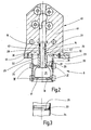
- Fig. 1 is a part of a conventional exhaust gas recirculation valve 10 is shown.
- This has a valve housing 11 and a valve member 12, the z. B. is designed plate-shaped.
- the valve member 12 is seated at the lower end of an upstanding lifting member 13 in the form of a valve stem which is guided in a shaft guide 14 which forms a sliding bearing for a vertical lifting movement in the drawing.
- the exhaust gas recirculation valve 10 is a lift valve.
- the lift member 13 is in Fig. 1 extended to the top, with a drive means for lifting operation attacks, of which only parts are visible and which is generally designated 15.
- Such a drive device 15 is known and requires no further detailed description.
- valve housing is here composed of two component units 20 and 40, of which the first component unit 20 includes a sealed valve chamber 21 and the second component unit 40 is formed as a housing part 41 for at least parts of the drive means 15 of the lifting member 13.
- the shaft guide 14, which forms a sliding bearing, is sealed at the upper end by means of a seal 16.
- the valve member 12 is associated with a valve seat ring 17 with approximately annular valve seat surface 18.
- closed position of the valve member 12 is this with an annular surface against the valve seat surface 18 in Fig. 1 pressed from below, whereby the passage to the valve chamber 21 is locked.
- the valve member 12 is opposite to the valve seat surface 18 away in Fig. 1 down to an open position movable under release of the passage in the region of the valve seat ring 17 to the valve chamber 21.
- the valve housing 11 has the cooling serving integrated cooling channels 19.
- the valve housing 11 is formed as a cast aluminum housing.
- the valve seat ring 17 with valve seat surface 18 may be made of stainless steel.
- the valve member 12 with lifting member 13 is not shown.
- the special feature consists in that the first component unit 20 is composed of a plurality of individual elements which are firmly and tightly connected together to form a whole in the form of a Anmaneiles 6, the housing part 41 of the second component unit 40 in Fig. 2 attached from below and connected by a flange 22 so that it is firmly connected, for. B. is screwed by means of screws 23.
- the screws 23 are indicated only schematically.
- the first component unit 20 as a single elements a the valve chamber 21 bounding tube member 24 and / or the lower in the drawing axial end of the valve chamber 21, in particular of the tubular member 24, arranged valve seat ring 17 and / or at an axial distance from the valve seat ring 17 in the drawing above the valve chamber 21 arranged, the valve chamber 21 axially bounding partition 25, wherein the partition wall 25, the valve chamber 21 in Fig. 2 separates upwards and closes tightly.
- a further individual element of the first component unit 20 is the shaft guide 14. This is designed as a tubular element 26 with a smooth continuous inner bore 27, a received in a bore 42 of the housing part 41 first cylinder portion 28 and a subsequent, in Fig.
- the described tube element 26 is inserted into the bore 42 of the housing part 41 of the second component unit 40 and secured with respect to the housing part 41.
- the tubular element 26, which forms the shaft guide 14 may be made of brass or, instead, advantageously consists of stainless steel.
- the second cylinder portion 29 of the tubular member 26 has at the lower end a stepped shoulder 31, on which the partition wall 25 is seated, radially centered and axially struck.
- the tubular element 26 is in this area by joining, z. B. pressing, or in a manner not shown by screws with the partition 25 firmly and tightly connected.
- the tube member 26 may be integral with the partition wall 25 and while the partition 25 also made of steel, preferably made of stainless steel.
- the first component unit 20 is fixedly connected to the flange 22 and by means of this on the housing part 41 z. B. fastened by means of screws 23.
- the tube part 24 of the first component unit 20 is connected to the flange 22 z. B. by welding, especially laser welding, or soldering, especially brazing firmly connected.
- the upper end of the tubular member 24 in the drawing can project beyond the flange 22 and engage with a collar 32 in a corresponding groove 44 in the lower surface 43 of the housing part 41 and if necessary also against rotation at this point in relation to the housing part 41 and / / or be attached to it.
- At least some individual elements of the first component unit 20 are formed from metallic turned parts produced by turning. This applies z. B. for the valve seat ring 17 and the partition 25.
- the tubular member 24 and / or the tubular member 26 may be formed of turned parts.
- the tube part 24 is formed from a metallic deep-drawn part.
- the tubular member 24 with the valve seat ring 17 and / or the partition 25 to a one-piece component, in particular deep-drawn part is united.
- the tube member 26 may be integral with the partition 25.
- valve seat ring 17 and / or the partition 25 may be formed from stampings.
- At least some individual elements of the first component unit 20 are made of steel, preferably of stainless steel. This applies in particular z. B. for the valve seat ring 17 and / or the partition wall 25 and / or the tube member 24 and / or the tube member 26.
- connection of at least some individual elements of the first component unit 20 comes in accordance with the first embodiment FIGS. 2 and 3 a connection by joining and crimping into consideration.
- z. B. for the valve seat ring 17 and / or the partition wall 25 which may be connected to the tubular member 24 by flare connection.
- Such a flare connection is shown as a detail III in Fig. 3 especially shown.
- the outer edge of the partition wall 25 positively engages in an annular groove 33 on the inside of the tubular member 24 and in this way the partition wall 25 is crimped with the tubular member 24.
- a same flare connection can also be provided between the valve seat ring 17 and the tube part 24.
- a flare connection between the tubular element 26 and the partition 25 is, if necessary, a flare connection between the tubular element 26 and the partition 25.
- the individual flanges are by soldering, in particular brazing, or welding, for. As laser welding, tightly connected, resulting in the latter case, the special advantage that no delay is to be feared.
- the housing part 41 of the second component unit 40 is formed as a die-cast part, in particular of aluminum. Instead, the training as stamped and bent part is possible.
- valve housing 11 Due to the described multi-part design can be used for the individual elements of the first component unit 20 for each most favorable material that is resistant to high temperatures.
- This allows a modular composition of the valve housing 11 in the form of the first component unit 20 and the second component unit 40. Due to the described design is a temperature resistance to z. B. about 1000 ° C possible.
- the valve seat ring 17 results in the rest of the advantage that either the lower surface forms the valve seat surface 18 or instead forms the opposite side of the valve seat surface. Both surfaces are similar and therefore suitable as valve seat surfaces.
- the design of the valve housing 11 in the manner described is particularly inexpensive. It thus allows an exhaust gas recirculation valve 10 high temperature resistance at very high gas temperatures, for example in the order of 1000 ° C and durable strength with favorable and cost-effective use of materials and correspondingly favorable processing and production.
- the same reference numerals are used for the same reasons for the above reasons.
- the second embodiment corresponds to the first embodiment with the exception of the connection of individual individual elements of the first component unit 20 with each other. Therefore, the foregoing description also applies to the second embodiment Fig. 2 but without flare connection, alike.
- At least some individual elements of the first component unit 20 are connected to each other by pressing on stop.
- Fig. 4 z. B the valve seat ring 17 and / or the partition wall 25 with the tube part 24 and / or the tube member 26 connected to the partition 25 by pressing against each other, wherein the areas of these press connections in Fig. 4 are indicated with IV.
- So z. B. a press connection between the tube member 26 and the partition 25 of the shape that the partition wall 25, as in the first embodiment, rests against the shoulder 31 and radially seated with a press fit on the second cylinder portion 29.
- the connection can be realized by pressing to stop.
- the individual press connections IV can by soldering, in particular brazing, or by welding, for. As laser welding, be firmly and tightly connected.
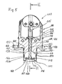
- FIG. 5 and 6 shown third embodiment are for the parts according to the first and second embodiment according to Fig. 2 to 4 by 100 greater reference numerals, thereby referring to the foregoing description to avoid unnecessary repetition.
- the exhaust gas recirculation valve 110 has a valve housing 111 and a valve member 112 which is movable via a drive means 115 by means of a rod-shaped lifting member 113 against a valve seat surface 118 of a valve seat ring 117 in the closed position or in opposite directions in an open position.
- the lifting member 113 is guided in a sleeve-shaped shaft guide 114.
- the valve member 112 blocks a passage 146 to a valve chamber 121 which is released in an open position, not shown. Then, the passage 146 supplied exhaust gas can pass into the valve chamber 121, in which it is deflected in a particularly streamlined manner by means of a curved ceiling surface 147 to an outlet 148.
- the valve housing 111 here consists of a one-piece housing unit 149, which has a in Fig. 5 and 6 lower, the ceiling surface 147 supporting and with this the valve chamber 121 delimiting the housing portion 150 and an integral upper housing part 141 which includes parts of the drive means 115 similar to the in Fig. 2 to 4
- the shaft guide 114 is held in the form of a tubular element 126, above which a seal 116 is provided.
- the Housing portion 150 is a radial flange 122 in one piece, which serves for mounting the valve on a terminal housing 151 and attaching thereto, wherein the housing portion 150 with a lower end surface 152 is seated flat on the terminal housing 151.
- the housing portion 150 is obviously combined with the housing part 141 of the upper component unit 140 to the one-piece housing unit 149.
- the latter is designed as a die-cast part, in particular of aluminum, and contains at least one shaft guide 114 near the adjacent channel 119 for coolant passage and thus for cooling the housing section 150.
- the lower end face 152 of the lower housing section 150 is followed by an approximately cylindrical valve member 112 outwardly directed neck 153 in one piece, which terminates in a narrow end surface 154 above the valve member 112.
- Lower component unit 120 has an approximately cup-shaped body part 160, which cooperates with the lower housing section 150, which adjoins the neck 153 and, together with the ceiling surface 147, delimits the valve chamber 122 and carries the valve seat ring 117 at the lower end.
- the approximately pot-shaped body part 160 has an approximately cylindrical wall part 161, which merges at the end in a valve seat ring 117 integral therewith. With an approximately cylindrical end portion 162, which is opposite to the valve seat ring 117, the body portion 160 is pushed onto the suitably dimensioned neck 153 of the housing portion 150 and centered. The body part 160 may be held firmly at the neck 153, z. B.
- the outer locking surfaces 164, z. B. an annular groove, engage behind the neck 153.
- the locking tabs 163 may be designed so that they rebound on pushing the body part 160 on the neck 153 to the outside and upon reaching the locking surfaces 164 compress and abut with the end of it. Instead, the body part 160 od also at the neck 153 by crimping, caulking. Like. Be held, z. B. by crimping a housing portion of the Wandungsteils 161 in a groove-shaped locking surface 164th
- the approximately cylindrical end portion 162 has at the end, which is opposite to the valve seat ring 117, a radially abstrebenden annular flange 165 which is received in a matching annular recess 166 of the housing portion 150.
- the annular flange 165 and the annular recess 166 are dimensioned such that the annular flange 165 closes on the underside approximately with the end face 152 of the housing section 150 and can rest flat on the terminal housing 151.
- the annular flange 165 is fixed within the annular recess between the housing portion 150 and the terminal housing 151.
- the annular flange 165 may be in the annular recess 166 z. B.
- the body part 160 is thus aligned in the axial direction and with the housing portion 150, in particular with the lifting member 113, in alignment. In this way, and the fact that the cylindrical wall portion 161 fits snugly on the neck 153, the body part 160 with valve seat ring 117 is aligned very precisely axially, radially and in alignment with the lifting member 113 and its valve member 120.
- the body part 160 may, at its wall part 161 at the height of the end face 154 of the neck 153, if necessary, still have an approximately annular infiltration to avoid flow losses at the end face 154 and better flow guidance there.
- valve seat ring 117 of the body part 160 is formed as a cross-sectionally approximately U-shaped torus ring 167 having an inner annular wall 168 which is directed towards the valve chamber 121 in the embodiment shown, in contrast, in another embodiment, in opposite directions down can be directed.
- the annular wall 168 defines the passage 146 and forms at the free edge of the ring Valve seat 118, the z. B. may be approximately cut-shaped.
- the valve seat surface 118 is machined to match the valve member 112.
- the approximately cup-shaped body part 160 is made of a metallic deep-drawn part made of sheet steel, for. B. high-temperature quality, formed.
- the valve member 112 is a valve disc, which is formed from a metallic deep-drawn part and fine blanking.
- the design of the approximately cup-shaped body part 160 as a boundary of the valve chamber 121 with the realization of the valve seat 118 thereby also results in a reduction in costs and due to the design as Deep-drawn part a special reduction in production costs.
- In the area of the valve chamber 121 and the valve seat ring 117 results due to the high exhaust gas temperatures, the largest temperature stress. This can be countered in a simple, cost-effective manner by the choice of material of the approximately cup-shaped body part 160.
- a flow-favorable design of the ceiling surface 147 can be realized in a simple, cost-effective manner by appropriate shaping during manufacture as a die-cast. Furthermore, the mating surfaces for receiving the approximately cup-shaped body part 160 can be realized in a simple manner and precisely during production. Overall, an exhaust gas recirculation valve 110 is thereby created, which is inexpensive and the use even at high temperatures and areas z. B. makes about 1000 ° C without damage possible and can work permanently.
- valve member 112 Due to the inner annular wall 168, the valve member 112 is pressed in the closed position of the valve chamber 121 in the drawing down on the valve seat surface 118 and held in this position by means of the drive means 115 as possible free of likelihood, so that the valve member 112 can reliably withstand the exhaust gas pressure acting thereon from the passage 146 in the closed position.
- the valve member 112 is moved toward the valve chamber 121 by means of the drive means 115, this opening movement being assisted and facilitated by the pressure of the exhaust gas acting on the valve member 112.
Abstract
Description
Die Erfindung bezieht sich auf ein Abgasrückführventil mit den Merkmalen im Oberbegriff des Anspruchs 1.The invention relates to an exhaust gas recirculation valve having the features in the preamble of claim 1.
Bei üblichen Abgasrückführventilen (
Der Erfindung liegt die Aufgabe zugrunde, ein Abgasrückführventil der eingangs genannten Art zu schaffen, das kostengünstig ist und den Einsatz auch bei hohen Temperaturen und Bereichen bis ca. 1000 °C ohne Schädigung möglich macht.The invention has for its object to provide an exhaust gas recirculation valve of the type mentioned, which is inexpensive and makes the use even at high temperatures and ranges up to about 1000 ° C without damage possible.
Die Aufgabe ist bei einem Abgasrückführventil der eingangs genannten Art gemäß der Erfindung dadurch gelöst, dass die eine Bauteileinheit fest und dicht miteinander verbundene Körperteile aufweist, die an das Gehäuseteil der anderen Bauteileinheit anschließen. Insbesondere können die Körperteile bei einem vorteilhaften Ausführungsbeispiel aus zusammengesetzten Einzelelementen bestehen, die zu einem Ganzen in Form eines Ansetzteiles verbunden sind, das an das Gehäuseteil der anderen Bauteileinheit angesetzt und damit fest verbunden ist, z. B. daran angeschraubt ist. Damit sind die Voraussetzungen dafür geschaffen, Einzelelemente der einen Bauteileinheit möglichst kostengünstig und zugleich dort, wo dies nötig ist, hochtemperaturfest zu gestalten. Eine Zusammensetzung nach Baukastensystem ist möglich. Dies reduziert bei Einsatz hochtemperaturfester Werkstoffe die Kosten wesentlich. Bei allem ist das Abgasrückführventil einfach, leicht, kompakt und kostengünstig.The object is achieved in an exhaust gas recirculation valve of the type mentioned according to the invention in that the one component unit has tightly and tightly interconnected body parts, which are connected to the housing part of connect other component unit. In particular, the body parts in an advantageous embodiment may consist of composite individual elements which are connected to form a whole in the form of a Ansetzteiles, which is attached to the housing part of the other component unit and thus firmly connected, for. B. is screwed to it. Thus, the conditions are created to make individual elements of a component unit as inexpensively as possible and at the same time, where necessary, high temperature resistant. A composition according to modular system is possible. This significantly reduces costs when using high-temperature resistant materials. In all, the exhaust gas recirculation valve is simple, lightweight, compact and inexpensive.
Eine vorteilhafte Ausführungsform sieht vor, dass die eine Bauteileinheit als Einzelelemente einen die Ventilkammer umgrenzenden Rohrteil und/oder den an einem axialen Ende der Ventilkammer angeordneten Ventilsitzring und/oder eine in axialem Abstand vom Ventilsitzring angeordnete, die Ventilkammer axial begrenzende Trennwand od. dgl. aufweist. Auch kann die eine Bauteileinheit als Einzelelement noch die Schaftführung aufweisen. Vorteilhaft ist die Schaftführung als Rohrelement ausgebildet, das in das Gehäuseteil der anderen Bauteileinheit eingesteckt ist und vorzugsweise diesem gegenüber gesichert ist. Dieses Rohrelement kann mit der Trennwand durch Fügen, z. B. Einpressen, oder durch Schrauben fest und dicht verbunden sein.An advantageous embodiment provides that the one component unit as individual elements od a valve chamber surrounding the tubular part and / or arranged at one axial end of the valve chamber valve seat ring and / or arranged at an axial distance from the valve seat ring, the valve chamber axially delimiting partition od. Like , Also, the one component unit may still have the shaft guide as a single element. Advantageously, the shaft guide is designed as a tubular element which is inserted into the housing part of the other component unit and is preferably secured against it. This pipe element can be connected to the partition by joining, z. B. pressing, or be firmly and tightly connected by screws.
Die eine Bauteileinheit ist mit einem Flansch fest verbunden und mittels des Flansches am Gehäuseteil der anderen Bauteileinheit befestigt, z. B. angeschraubt. Dabei kann der Rohrteil der einen Bauteileinheit mit dem Flansch mittels Schweißen, insbesondere Laserschweißen, oder Löten, insbesondere Hartlöten, fest verbunden sein. Der Rohrteil der einen Bauteileinheit kann mit einem Ende am Gehäuseteil der anderen Bauteileinheit verdrehgesichert aufgenommen und bedarfsweise befestigt sein.One component unit is firmly connected to a flange and fixed by means of the flange on the housing part of the other component unit, for. B. screwed. In this case, the tube part of a component unit with the flange by means of welding, in particular laser welding, or soldering, in particular brazing, be firmly connected. The tube part of the one component unit can be held against rotation with one end on the housing part of the other component unit and fastened as needed.
Von Vorteil kann es sein, wenn zumindest einige Einzelelemente der einen Bauteileinheit aus metallischen, durch Drehbearbeitung hergestellten Drehteilen gebildet sind, insbesondere z. B. der Ventilsitzring und/oder die Trennwand und/oder der Rohrteil und/oder das Rohrelement. Derartige Drehteile sind kostengünstig herstellbar, und zwar auch dann, wenn die Einzelelemente aus unterschiedlichen Materialien bestehen.It may be advantageous if at least some individual elements of a component unit are formed from metallic, produced by turning rotary parts, in particular z. B. the valve seat ring and / or the partition wall and / or the pipe part and / or the pipe element. Such turned parts are inexpensive to produce, even if the individual elements made of different materials.
Der Rohrteil kann mit Vorteil aus einem metallischen Tiefziehteil gebildet sein. In einem solchen Fall kann es ferner vorteilhaft sein, wenn der Rohrteil mit dem Ventilsitzring und/oder der Trennwand zu einem einstückigen Bauteil vereinigt ist. Auch kann es vorteilhaft sein, wenn das Rohrelement einstückig mit der Trennwand ist.The pipe part can be advantageously formed from a metallic deep-drawn part. In such a case, it may also be advantageous if the tube part is combined with the valve seat ring and / or the partition wall to form a one-piece component. It may also be advantageous if the pipe element is integral with the partition wall.
Bei einer weiteren vorteilhaften Ausführungsform ist vorgesehen, dass der Flansch aus einem Stanzteil gebildet ist. Statt aus Drehteilen können zumindest einige Einzelelemente der einen Bauteileinheit auch aus Stanzteilen, die kostengünstig sind, gebildet sein, z. B. der Ventilsitzring und/oder die Trennwand.In a further advantageous embodiment it is provided that the flange is formed from a stamped part. Instead of turned parts, at least some individual elements of a component unit can also be formed from stamped parts, which are inexpensive, z. B. the valve seat ring and / or the partition.
Von besonderem Vorteil kann es sein, wenn zumindest einige Einzelelemente der einen Bauteileinheit aus Stahl, vorzugsweise aus Edelstahl, gebildet sind. Dadurch ist der Einsatz auch bei sehr hohen Temperaturen möglich, ohne Schäden und Festigkeitsverluste befürchten zu müssen. Insbesondere können z. B. der Ventilsitzring und/oder die Trennwand und/oder der Rohrteil und/oder das Rohrelement aus Stahl, vorzugsweise Edelstahl, bestehen.It may be of particular advantage if at least some individual elements of a component unit made of steel, preferably made of stainless steel, are formed. Thus, the use is possible even at very high temperatures, without having to fear damage and strength losses. In particular, z. B. the valve seat ring and / or the partition wall and / or the pipe part and / or the pipe element made of steel, preferably stainless steel.
Bezüglich der Verbindung zumindest einiger Einzelelemente der einen Bauteileinheit miteinander kann es von Vorteil sein, diese durch Fügen und Verbördeln miteinander zu verbinden. Dies kann insbesondere z. B. für die Verbindung des Ventilsitzringes und/oder der Trennwand mit dem Rohrteil gelten. Auch eine Bördelverbindung zwischen dem Rohrelement und der Trennwand kann vorteilhaft sein. Die einzelnen Bördelungen sind dabei vorteilhaft durch Löten, insbesondere Hartöten, oder Schweißen, z. B. Laserschweißen, fest und dicht verbunden.With regard to the connection of at least some individual elements of a component unit with each other, it may be advantageous to connect them together by joining and flanging. This can in particular z. B. apply to the connection of the valve seat ring and / or the partition with the pipe part. A flare connection between the pipe element and the partition may be advantageous. The individual curls are advantageous by Soldering, in particular brazing, or welding, z. As laser welding, firmly and tightly connected.
Statt dessen kann es ebenfalls von Vorteil sein, wenn zumindest einige Einzelelemente der einen Bauteileinheit durch Pressen auf Anschlag miteinander verbunden sind, insbesondere z. B. der Ventilsitzring und/oder die Trennwand mit dem Rohrteil und/oder das Rohrelement mit der Trennwand. Diese Pressverbindungen können durch Löten, insbesondere Hartlöten, oder Schweißen, z. B. Laserschweißen, gesichert sein. Sowohl die Bördelverbindungen als auch die Pressverbindungen lassen sich schnell und einfach und damit kostengünstig herstellen, wobei eine Dichtheit in beschriebener Weise durch Löten oder Schweißen erzielbar ist, ohne hierbei einen Verzug der Einzelelemente befürchten zu müssen.Instead, it may also be advantageous if at least some individual elements of a component unit are connected to each other by pressing to stop, in particular z. B. the valve seat ring and / or the partition with the pipe part and / or the pipe element with the partition. These press connections can be made by soldering, in particular brazing, or welding, for. As laser welding, be secured. Both the flare and the press connections can be produced quickly and easily and thus cost, with a tightness in the manner described by soldering or welding can be achieved without having to fear a delay of the individual elements.
Das Gehäuseteil der anderen Bauteileinheit ist zweckmäßigerweise als Druckgußteil, insbesondere aus Aluminium, oder statt dessen als Stanzbiegeteil ausgebildet.The housing part of the other component unit is expediently designed as a die-cast part, in particular made of aluminum, or instead as a stamped and bent part.
Das Rohrelement der Schaftführung kann statt aus Stahl, insbesondere Edelstahl, auch aus Messing bestehen.The tubular element of the shaft guide may instead of steel, especially stainless steel, also made of brass.
Bei anderen vorteilhaften Ausführungsform eines Abgasrückführventils ist vorgesehen, dass die eine Bauteileinheit aus einem etwa topfförmigen Körperteil mit einem etwa zylindrischen Wandungsteil und damit einstückigen endseitigen Ventilsitzring sowie einem mit dem Gehäuseteil der anderen Bauteileinheit einstückigen, der Antriebseinrichtung gegenüberliegenden Gehäuseabschnitt gebildet ist, an den der etwa topfförmige Körperteil angeschlossen ist und der zusammen mit dem etwa topfförmigen Körperteil die Ventilkammer umgrenzt. Hierbei ist also ausgehend vom eingangs erläuterten anderen Ausführungsbeispiel der oberhalb der Trennwand befindliche Rohrteil mit der Trennwand ersetzt durch einen mit dem Gehäuseteil der anderen Bauteileinheit einstückigen Gehäuseabschnitt. Der die Ventilkammer anschließend an diesen Gehäuseabschnitt begrenzende Teil ist durch den etwa topfförmigen Körperteil gebildet, und zwar durch dessen etwa zylindrischen Wandungsteil mit damit einstückigem endseitigen Ventilsitzring. Dadurch ergibt sich nur ein einstückiges Gehäuse, das in kostengünstiger Weise als Gehäuseeinheit aus einem Druckgußteil, insbesondere aus Aluminium, hergestellt werden kann, wobei im Inneren dieser Gehäuseeinheit auch zumindest ein Kanal zur Kühlmitteldurchleitung gebildet werden kann, der dabei möglichst nah benachbart der Schaftführung verlaufen kann. Durch diese Bauweise kann eine gute Abfuhr der Wärme erfolgen, die aus der Ventilkammer über das Hubglied in dem Ventilglied abgewandter Richtung geleitet wird. Dies ist wegen der hohen Temperaturen des die Ventilkammer passierenden, gesteuerten Abgases von wesentlicher Bedeutung. Eine z. B. aus Aluminiumdruckguß gestaltete Gehäuseeinheit fördert die Wärmeabfuhr und begünstigt die Kühlung. Der im Hinblick auf die hohen Temperaturen kritische Bereich beim Ventilsitz und dem Ventilglied dagegen kann aufgrund des etwa topfförmigen Körperteils aus Metallblech und einem Tiefziehteil kostengünstig hergestellt werden, wobei die Materialauswahl dafür an die hohen Temperaturen in diesem unteren Bereich des Abgasrückführventils angepasst und optimiert werden kann. Dabei ist ein derartiger etwa topfförmiger Körperteil am unteren Ende der Gehäuseeinheit ein einfaches, kostengünstiges Bauteil, das mit radialer Zentrierung und axialer Lagesicherung und koaxialer Fluchtung in Bezug auf die Gehäuseeinheit positioniert und angebracht werden kann. Der etwa topfförmige Körperteil kann fest mit der Gehäuseeinheit verbunden sein. Vorteilhaft ist dabei eine radiale und axiale sowie koaxiale fluchtende Aufnahme des Körperteils an der Gehäuseeinheit derart, dass der Körperteil in Bezug auf die Gehäuseeinheit zuverlässig radial und axial ausgerichtet und fluchtend koaxial zum Hubglied gehalten ist. Der Körperteil kann axial zwischen dem unteren Ende der Gehäuseeinheit und einem diesen aufnehmenden Anschlussgehäuse platziert und radial und axial gehalten sein.In another advantageous embodiment of an exhaust gas recirculation valve is provided that the one component unit from an approximately cup-shaped body part with an approximately cylindrical wall part and thus integral end-side valve seat ring and one integral with the housing part of the other component unit, the drive means opposite housing portion is formed, to which the approximately cup-shaped Body part is connected and defines the valve chamber together with the approximately cup-shaped body part. In this case, starting from the other exemplary embodiment explained at the outset, the pipe part located above the dividing wall with the dividing wall is replaced by one with the housing part of the other component unit one-piece housing section. The valve chamber subsequent to this housing section limiting part is formed by the approximately cup-shaped body part, by its approximately cylindrical wall part with it one-piece end valve seat ring. This results in only a one-piece housing, which can be produced in a cost effective manner as a housing unit of a die-cast, in particular aluminum, wherein at least one channel for coolant passage can be formed inside this housing unit, which can be as close as possible adjacent the shaft guide , By this construction, a good dissipation of the heat can be carried out, which is directed from the valve chamber via the lifting member in the valve member facing away. This is because of the high temperatures of the valve chamber passing, controlled exhaust gas essential. A z. B. die-cast aluminum housing unit promotes heat dissipation and favors the cooling. The critical in terms of the high temperatures area the valve seat and the valve member, however, can be produced inexpensively due to the approximately cup-shaped body part made of sheet metal and a deep-drawn part, the material selection can be adapted and optimized for the high temperatures in this lower region of the exhaust gas recirculation valve. In this case, such an approximately cup-shaped body part at the lower end of the housing unit is a simple, inexpensive component that can be positioned and mounted with radial centering and axial position assurance and coaxial alignment with respect to the housing unit. The approximately pot-shaped body part can be firmly connected to the housing unit. A radial and axial and coaxial alignment of the body part with the housing unit is advantageous in such a way that the body part is reliably radially and axially aligned relative to the housing unit and held coaxially with the lifting member in alignment. The body part may be placed axially between the lower end of the housing unit and a terminal housing receiving it and held radially and axially.
Vorteilhaft kann es sein, wenn der etwa topfförmige Körperteil mit einem etwa zylindrischen Endteil, der dem Ventilsitzring gegenüberliegt, auf einem passend zylindrischen Hals des Gehäuseabschnitts aufgeschoben und zentriert ist. Dabei kann in vorteilhafter Weise der etwa zylindrische Endteil an dem Ende, das dem Ventilsitzring gegenüberliegt, einen radial abstehenden Ringflansch aufweisen, der in einer passenden Ringeintiefung des Gehäuseabschnitts aufgenommen und z. B. durch Bördeln und Verstemmen befestigt ist.It may be advantageous if the approximately cup-shaped body part with an approximately cylindrical end part, which is opposite to the valve seat ring, is pushed and centered on a suitably cylindrical neck of the housing section. In this case, advantageously, the approximately cylindrical end portion at the end, which is opposite to the valve seat ring, having a radially projecting annular flange, which is received in a matching annular recess of the housing portion and z. B. is fixed by crimping and caulking.
Vorteilhaft kann es ferner sein, wenn der etwa topfförmige Körperteil am Hals des Gehäuseabschnitts befestigt ist, z. B. mittels eines in eine z. B. nutförmige Rastfläche am Hals des Gehäuseabschnitts eingebördelten oder verstemmten Gehäusebereichs des Wandungsteils oder z. B. mittels aus dem Wandungsteil ausgeklinkter Rastlaschen, die Rastflächen am Hals des Gehäuseabschnitts hintergreifen.It may also be advantageous if the approximately cup-shaped body part is attached to the neck of the housing portion, z. B. by means of a z. B. groove-shaped locking surface on the neck of the housing portion crimped or caulked housing portion of the wall part or z. B. by means of the wall part notched locking tabs engage behind the locking surfaces on the neck of the housing portion.
Eine weitere vorteilhafte Ausführungsform sieht vor, dass der mit dem Wandungsteils einstückige Ventilsitzring des etwa topfförmigen Körperteils als im Querschnitt etwa U-förmiger Torusring ausgebildet ist und eine vorzugsweise zur Ventilkammer hin gerichtete innere Ringwandung aufweist, welche einen in Öffnungsstellung des Ventilgliedes mit der Ventilkammer in Verbindung stehenden Durchlaß umgrenzt und am freien Ringrand die Ventilsitzfläche bildet, die in Anpassung an das Ventilglied bearbeitet ist.A further advantageous embodiment provides that the integral with the wall part valve seat ring of approximately cup-shaped body part is formed as a cross-sectionally approximately U-shaped torus ring and a preferably directed towards the valve chamber inner annular wall, which in an open position of the valve member with the valve chamber in connection circumscribed by the passage and formed at the free edge of the ring, the valve seat surface, which is machined in adaptation to the valve member.
Von Vorteil kann es sein, wenn der etwa topfförmige Körperteil aus einem Tiefziehteil aus Metallblech gebildet ist.It may be advantageous if the approximately cup-shaped body part is formed from a deep-drawn part of sheet metal.
Eine weitere vorteilhafte Ausführungsform sieht vor, dass das Ventilglied ein Ventilteller ist, der aus einem metallischen Tiefziehteil und Feinstanzteil gebildet ist.A further advantageous embodiment provides that the valve member is a valve disk, which is formed from a metallic deep-drawn part and fine blank.
Der Ventilsitzring des etwa topfförmigen Körperteils kann in vorteilhafter Weise so gestaltet sein, dass das Ventilglied in Schließstellung von der Ventilkammer her auf die Ventilsitzfläche gedrückt wird, insbesondere mittels der Antriebseinrichtung und dadurch in Schließstellung gehalten ist. Zum Öffnen ist das Ventilglied gegensinnig in Richtung zur Ventilkammer hin und in diese hinein in seine Öffnungsstellung bewegbar.The valve seat ring of the approximately pot-shaped body part can be designed in an advantageous manner so that the valve member is pressed in the closed position of the valve chamber forth on the valve seat surface, in particular by means of the drive means and thereby held in the closed position. To open the valve member in the opposite direction in the direction of the valve chamber and into this into its open position movable.
Vorteilhaft kann es ferner sein, wenn die zur Ventilkammer weisende und diese abgrenzende untere Gehäusefläche des Gehäuseabschnitts als strömungsgünstig gewölbte Deckenfläche ausgebildet ist. Dabei führt diese Wölbung bis hin zu einem mit der Ventilkammer in Verbindung stehenden Auslaß. Aufgrund der Gestaltung als Gehäuseeinheit in Form eines Druckgußteils ist diese strömungsgünstige Formgebung der Deckenfläche des Ventilkammersitzes in kostengünstiger und einfacher Weise möglich.It can also be advantageous if the lower housing surface of the housing section facing the valve chamber and delimiting it is designed as a curved surface which is curved in a flow-favorable manner. This curvature leads up to an outlet communicating with the valve chamber. Due to the design as a housing unit in the form of a die casting this aerodynamic shaping of the ceiling surface of the valve chamber seat is possible in a cost effective and simple manner.
Bei der beschriebenen Gestaltung des Abgasrückventils ist der Gehäuseabschnitt mit dem Gehäuseteil der anderen Bauteileinheit somit zu einer einstückigen Gehäuseeinheit vereinigt, wobei diese Gehäuseeinheit als Druckgußteil, insbesondere aus Aluminium, ausgebildet ist und im Inneren zumindest einen der Schaftführung nah benachbarten Kanal zur Kühlmitteldurchleitung enthält.In the described design of the exhaust gas return valve, the housing portion is thus combined with the housing part of the other component unit to form a one-piece housing unit, said housing unit is formed as a die-cast, in particular aluminum, and contains at least one of the shaft guide closely adjacent channel to the coolant passage.
Weitere Vorteile und Einzelheiten der Erfindung ergeben sich aus der nachfolgenden Beschreibung.Further advantages and details of the invention will become apparent from the following description.
Die Erfindung ist nachfolgend anhand von in den Zeichnungen gezeigten Ausführungsbeispielen näher erläutert. Es zeigen:
- Fig. 1
- einen schematischen senkrechten Schnitt eines Teils eines Abgasrückführventils üblicher Art,
- Fig. 2
- einen schematischen senkrechten Schnitt eines Teils eines Abgasrückführventils erfindungsgemäßer Art, gemäß einem ersten Ausführungsbeispiel,
- Fig. 3
- einen schematischen Schnitt der Einzelheit III in
Fig. 2 mit teilweiser Seitenansicht, - Fig. 4
- einen schematischen Schnitt eines Teils eines erfindungsgemäßen Abgasrückführventils gemäß einem zweiten Ausführungsbeispiel,
- Fig. 5
- einen schematischen Schnitt eines Teils eines erfindungsgemäßen Abgasrückführventils gemäß einem dritten Ausführungsbeispiel,
- Fig. 6
- einen schematischen Schnitt des Abgasrückführventils in
Fig. 5 entlang der Linie VI-VI inFig. 5
- Fig. 1
- a schematic vertical section of a portion of an exhaust gas recirculation valve of conventional type,
- Fig. 2
- a schematic vertical section of a part of an exhaust gas recirculation valve according to the invention, according to a first embodiment,
- Fig. 3
- a schematic section of the detail III in
Fig. 2 with partial side view, - Fig. 4
- FIG. 2 a schematic section of a part of an exhaust gas recirculation valve according to the invention according to a second exemplary embodiment, FIG.
- Fig. 5
- a schematic section of a portion of an exhaust gas recirculation valve according to the invention according to a third embodiment,
- Fig. 6
- a schematic section of the exhaust gas recirculation valve in
Fig. 5 along the line VI-VI inFig. 5
In
Dem Ventilglied 12 ist ein Ventilsitzring 17 mit etwa ringförmiger Ventilsitzfläche 18 zugeordnet. In der in
Abhilfe ist hier mittels eines erfindungsgemäßen Abgasrückführventils 10 gemäß dem ersten Ausführungsbeispiel in
Beim Beispiel gemäß
Im Detail weist die erste Bauteileinheit 20 als Einzelelemente einen die Ventilkammer 21 umgrenzenden Rohrteil 24 und/oder den am in der Zeichnung unteren axialen Ende der Ventilkammer 21, insbesondere des Rohrteils 24, angeordneten Ventilsitzring 17 und/oder eine in axialem Abstand vom Ventilsitzring 17 in der Zeichnung oberhalb der Ventilkammer 21 angeordnete, die Ventilkammer 21 axial begrenzende Trennwand 25 auf, wobei die Trennwand 25 die Ventilkammer 21 in
Das beschriebene Rohrelement 26 ist in die Bohrung 42 des Gehäuseteils 41 der zweiten Bauteileinheit 40 eingesteckt und in Bezug auf den Gehäuseteil 41 gesichert. Das Rohrelement 26, das die Schaftführung 14 bildet, kann aus Messing bestehen oder es besteht statt dessen in vorteilhafter Weise aus Edelstahl.The described
Der zweite Zylinderabschnitt 29 des Rohrelements 26 weist am unteren Ende eine abgestufte Schulter 31 auf, auf der die Trennwand 25 sitzt, und zwar radial zentriert und axial angeschlagen ist. Das Rohrelement 26 ist in diesem Bereich durch Fügen, z. B. Einpressen, oder in nicht gezeigter Weise durch Schrauben mit der Trennwand 25 fest und dicht verbunden.The
Bei einem anderen, nicht gezeigten Ausführungsbeispiel kann das Rohrelement 26 mit der Trennwand 25 einstückig sein und dabei wie die Trennwand 25 auch aus Stahl, vorzugsweise aus Edelstahl, bestehen.In another, not shown embodiment, the
Die erste Bauteileinheit 20 ist mit dem Flansch 22 fest verbunden und mittels dieses am Gehäuseteil 41 z. B. mittels der Schrauben 23 befestigt. Der Rohrteil 24 der ersten Bauteileinheit 20 ist mit dem Flansch 22 z. B. mittels Schweißen, insbesondere Laserschweißen, oder Löten, insbesondere Hartlöten, fest verbunden. Das in der Zeichnung obere Ende des Rohrteils 24 kann über den Flansch 22 überstehen und mit einem Ringbund 32 in eine entsprechende Nut 44 in der unteren Fläche 43 des Gehäuseteils 41 eingreifen und bei Bedarf auch an dieser Stelle in Bezug auf den Gehäuseteil 41 verdrehgesichert und/oder damit befestigt sein.The
Zumindest einige Einzelelemente der ersten Bauteileinheit 20 sind aus metallischen, durch Drehbearbeitung hergestellten Drehteilen gebildet. Dies gilt z. B. für den Ventilsitzring 17 und die Trennwand 25. Auch der Rohrteil 24 und/oder das Rohrelement 26 können aus Drehteilen gebildet sein.At least some individual elements of the
Von Vorteil kann es sein, wenn der Rohrteil 24 aus einem metallischen Tiefziehteil gebildet ist. In diesem Fall kann es weiterhin vorteilhaft sein, wenn der Rohrteil 24 mit dem Ventilsitzring 17 und/oder der Trennwand 25 zu einem einstückigen Bauteil, insbesondere Tiefziehteil, vereinigt ist. Auch kann das Rohrelement 26 mit der Trennwand 25 einstückig sein.It may be advantageous if the
Der Flansch 22 und/oder zumindest einige Einzelelemente der ersten Bauteileinheit 20, z. B. der Ventilsitzring 17 und/oder die Trennwand 25, können aus Stanzteilen gebildet sein.The
In vorteilhafter Weise sind zumindest einige Einzelelemente der ersten Bauteileinheit 20 aus Stahl, vorzugsweise aus Edelstahl, gebildet. Dies gilt insbesondere z. B. für den Ventilsitzring 17 und/oder die Trennwand 25 und/oder den Rohrteil 24 und/oder das Rohrelement 26. Hinsichtlich der Verbindung zumindest einiger Einzelelemente der ersten Bauteileinheit 20 kommt beim ersten Ausführungsbeispiel gemäß
Das Gehäuseteil 41 der zweiten Bauteileinheit 40 ist als Druckgußteil ausgebildet, insbesondere aus Aluminium. Statt dessen ist auch die Ausbildung als Stanzbiegeteil möglich.The
Aufgrund der beschriebenen mehrteiligen Gestaltung kann für die Einzelelemente der ersten Bauteileinheit 20 das dafür jeweils günstigste Material eingesetzt werden, das hochtemperaturfest ist. Dies ermöglicht eine baukastenartige Zusammensetzung des Ventilgehäuses 11 in Form der ersten Bauteileinheit 20 und der zweiten Bauteileinheit 40. Durch die beschriebene Ausbildung ist eine Temperaturfestigkeit bis z. B. etwa 1000 °C möglich. Hinsichtlich des Ventilsitzringes 17 ergibt sich im übrigen der Vorteil, dass entweder dessen untere Fläche die Ventilsitzfläche 18 bildet oder statt dessen die gegenüberliegende Seite die Ventilsitzfläche bildet. Beide Flächen sind gleichartig und daher als Ventilsitzflächen geeignet. Die Gestaltung des Ventilgehäuses 11 in beschriebener Weise ist besonders kostengünstig. Sie ermöglicht somit ein Abgasrückführventil 10 großer Temperaturfestigkeit bei sehr hohen Gastemperaturen etwa in der Größenordnung von 1000 °C und dauerhafte Festigkeit bei günstigem und kostengünstigem Materialeinsatz und entsprechend günstiger Bearbeitung und Herstellung.Due to the described multi-part design can be used for the individual elements of the
Bei dem in
Beim Ausführungsbeispiel gemäß
So sind gemäß
Im Übrigen gilt die Beschreibung zum ersten Ausführungsbeispiel gleichermaßen auch für das zweite Ausführungsbeispiel gemäß
Bei dem in
Das Abgasrückführventil 110 gemäß
Das Ventilgehäuse 111 besteht hier aus einer einstückigen Gehäuseeinheit 149, die einen in
Der Gehäuseabschnitt 150 ist ersichtlich mit dem Gehäuseteil 141 der oberen Bauteileinheit 140 zu der einstückigen Gehäuseeinheit 149 vereinigt. Letzere ist als Druckgußteil, insbesondere aus Aluminium, ausgebildet und enthält im Inneren zumindest einen der Schaftführung 114 nah benachbarten Kanal 119 zur Kühlmitteldurchleitung und damit zur Kühlung des Gehäuseabschnitts 150. An die untere Stirnfläche 152 des unteren Gehäuseabschnitts 150 schließt sich ein etwa zylindrischer, zum Ventilglied 112 hin gerichteter Hals 153 einstückig an, der in einer schmalen Endfläche 154 oberhalb des Ventilgliedes 112 ausläuft.The
Die in
Dies hat den Vorteil, dass bei der Befestigung des Körperteils 160 keine Relativbewegung in Bezug auf den Hals 153 geschieht und somit dessen Position nicht verändert wird.This has the advantage that in the attachment of the
Der etwa zylindrische Endteil 162 weist an dem Ende, das dem Ventilsitzring 117 gegenüberliegt, einen radial abstrebenden Ringflansch 165 auf, der in einer passenden Ringeintiefung 166 des Gehäuseabschnitts 150 aufgenommen ist. Der Ringflansch 165 und die Ringeintiefung 166 sind so bemessen, dass der Ringflansch 165 unterseitig etwa mit der Stirnfläche 152 des Gehäuseabschnitts 150 abschließt und flächig am Anschlußgehäuse 151 aufliegen kann. Der Ringflansch 165 ist innerhalb der Ringeintiefung zwischen dem Gehäuseabschnitt 150 und dem Anschlußgehäuse 151 fixiert. Der Ringflansch 165 kann in der Ringeintiefung 166 z. B. durch Verbördeln oder Verstemmen des Materials des Gehäuseabschnitts 150 befestigt sein. Der Körperteil 160 ist somit in Axialrichtung und mit dem Gehäuseabschnitt 150, insbesondere mit dem Hubglied 113, in einer Flucht ausgerichtet. Auf diese Weise und dadurch, dass der zylindrische Wandungsteil 161 auf dem Hals 153 passgenau aufsitzt, ist der Körperteil 160 mit Ventilsitzring 117 sehr genau axial, radial und fluchtend auf das Hubglied 113 und dessen Ventilglied 120 ausgerichtet.The approximately
Der Körperteil 160 kann bei seinem Wandungsteil 161 auf Höhe der Endfläche 154 des Halses 153 bedarfsweise noch eine etwa ringförmige Versickung aufweisen zur Vermeidung von Strömungsverlusten bei der Endfläche 154 und zur besseren Strömungsführung dort.The
Der mit dem Wandungsteil 161 einstückige Ventilsitzring 117 des Körperteils 160 ist als im Querschnitt etwa U-förmiger Torusring 167 gebildet, der eine innere Ringwandung 168 aufweist, die beim gezeigten Ausführungsbeispiel zur Ventilkammer 121 hin gerichtet ist, bei einem anderen Ausführungsbeispiel hingegen gegensinnig dazu nach unten gerichtet sein kann. Die Ringwandung 168 umgrenzt den Durchlaß 146 und bildet am freien Ringrand die Ventilsitzfläche 118, die z. B. etwa schneidenförmig sein kann. Die Ventilsitzfläche 118 ist in Anpassung an das Ventilglied 112 bearbeitet.The integral with the
Der etwa topfförmige Körperteil 160 ist aus einem metallischen Tiefziehteil aus Stahlblech, z. B. hochwarmfester Qualität, gebildet.The approximately cup-shaped
Das Ventilglied 112 ist ein Ventilteller, der aus einem metallischen Tiefziehteil und Feinstanzteil gebildet ist. Dadurch ergibt sich eine Vereinfachung der Herstellung mit Reduzierung der Fertigungskosten sowie eine Gewichtsreduzierung für das Ventilglied 112. Durch die Gestaltung des etwa topfförmigen Körperteils 160 als Umgrenzung der Ventilkammer 121 mit Verwirklichung der Ventilsitzfläche 118 daran ergibt sich ebenfalls eine Reduzierung der Kosten und aufgrund der Gestaltung als Tiefziehteil eine besondere Reduzierung der Fertigungskosten. Im Bereich der Ventilkammer 121 und des Ventilsitzringes 117 ergibt sich aufgrund der hohen Abgastemperaturen die größte Temperaturbeanspruchung. Dem kann in einfacher, kostengünstiger Weise durch die Materialwahl des etwa topfförmigen Körperteils 160 begegnet werden. Aufgrund des unteren Gehäuseabschnitts 150, der mit dem Ventilgehäuse 111 einstückig ist, kann durch entsprechende Formgebung bei der Herstellung als Druckgußteil eine strömungsgünstige Gestaltung der Deckenfläche 147 in einfacher, kostengünstiger Weise verwirklicht werden. Ferner lassen sich bei der Herstellung die Passflächen zum Aufnehmen des etwa topfförmigen Körperteils 160 in einfacher Weise und genau verwirklichen. Insgesamt ist dadurch ein Abgasrückführventil 110 geschaffen, das kostengünstig ist und den Einsatz auch bei hohen Temperaturen und Bereichen z. B. ca. 1000°C ohne Schädigung möglich macht und dauerhaft arbeiten kann.The
Aufgrund der inneren Ringwandung 168 wird das Ventilglied 112 in der Schließstellung von der Ventilkammer 121 aus in der Zeichnung nach unten auf die Ventilsitzfläche 118 gedrückt und in dieser Position mittels der Antriebseinrichtung 115 möglichst lekagefrei gehalten, so dass das Ventilglied 112 dem darauf vom Durchlaß 146 her einwirkenden Abgasdruck in Schließstellung zuverlässig standhalten kann. Für die Öffnungsstellung wird das Ventilglied 112 in Richtung zur Ventilkammer 121 hin mittels der Antriebseinrichtung 115 bewegt, wobei diese Öffnungsbewegung durch den auf das Ventilglied 112 einwirkenden Druck des Abgases unterstützt und erleichtert wird. Dies hat den Vorteil, dass die Antriebseinrichtung 115 hinsichtlich ihrer einzelnen Elemente, nämlich Antriebsmotor und Getriebe, kleiner und leichter dimensioniert werden kann und damit auch in diesem Bereich eine Kostenreduzierung erreichbar ist.Due to the inner
Claims (15)
dadurch gekennzeichnet,
dass die eine Bauteileinheit (20; 120) fest und dicht verbundene Körperteile aufweist, die an das Gehäuseteil (41; 141) der anderen Bauteileinheit (40; 140) anschließen.Exhaust gas recirculation valve, comprising a valve housing (11; 111) and a valve member (12; 112), which is displaceable against a valve seat surface (18; 113) via a drive member (15; 115) by means of a lifting member (13; 113) guided in a shaft guide (14; 114) 118) of a valve seat ring (17, 117) in the closed position or in the opposite direction is movable into an open position and blocks or opens the passage to a valve chamber (21, 121), wherein the valve housing (11; 20, 40, 120, 140), of which one component unit (20, 120) delimits at least the tightly sealed valve chamber (21, 121) and another component unit (40, 140) defines a housing part (41, 141) for at least parts the drive device (15; 115) of the lifting member (13; 113) has,
characterized,
in that the one component unit (20; 120) has tightly and tightly connected body parts which adjoin the housing part (41; 141) of the other component unit (40; 140).
dadurch gekennzeichnet,
dass die Körperteile aus zusammengesetzen Einzelelementen bestehen, die zu einem Ganzen in Form eines Ansetzteils (6) verbunden sind, das an das Gehäuseteil (41) der anderen Bauteileinheit (40) angesetzt und damit fest verbunden ist, z. B. durch Schrauben, Bördeln, Verstemmen, Verpressen od. dgl., wobei vorzugsweise die eine Bauteileinheit (20) als Einzelelemente einen die Ventilkammer (21) umgrenzenden Rohrteil (24) und/oder den an einem axialen Ende der Ventilkammer (21) angeordneten Ventilsitzring (17) und/oder eine in axialem Abstand vom Ventilsitzring (17) angeordnete, die Ventilkammer (21) axial begrenzende Trennwand (25) und/oder die Schaftführung (14) aufweist und wobei vorzugsweise die Schaftführung (14) als Rohrelement (26), z. B. aus Messing, ausgebildet ist, das in das Gehäuseteil (41) der anderen Bauteileinheit (40) eingesteckt ist und vorzugsweise diesem gegenüber gesichert ist und/oder mit der Trennwand (25) durch Fügen, z. B. Einpressen, oder durch Schrauben fest und dicht verbunden ist.Exhaust gas recirculation valve according to claim 1,
characterized,
that the body parts consist of composite individual elements which are connected to form a whole in the form of a Ansetzteils (6), which is attached to the housing part (41) of the other component unit (40) and fixedly connected thereto, for. B. by screws, flanging, caulking, compression od. Like., Preferably one component unit (20) as a single elements a valve chamber (21) delimiting tube part (24) and / or arranged at one axial end of the valve chamber (21) Valve seat ring (17) and / or arranged at an axial distance from the valve seat ring (17), the valve chamber (21) axially delimiting partition (25) and / or the shaft guide (14) and preferably wherein the shaft guide (14) as a tubular element (26 ), z. B. made of brass, which is inserted into the housing part (41) of the other component unit (40) and preferably secured against this and / or with the partition (25) by joining, for. B. pressing, or firmly and tightly connected by screws.
dadurch gekennzeichnet,
dass die eine Bauteileinheit (20) mit einem Flansch (22) fest verbunden ist und mittels des Flansches (22) am Gehäuseteil (41) der anderen Bauteileinheit (40) befestigt ist, z. B. angeschraubt ist, und vorzugsweise, dass der Rohrteil (24) der einen Bauteileinheit (20) mit dem Flansch (22) mittels Schweißen, insbesondere Laserschweißen, oder Löten, insbesondere Hartlöten, fest verbunden ist und vorzugsweise mit einem Ende am Gehäuseteil (41) der anderen Bauteileinheit (40) verdrehgesichert aufgenommen und bedarfsweise befestigt ist.Exhaust gas recirculation valve according to claim 2,
characterized,
in that the one component unit (20) is firmly connected to a flange (22) and is fastened by means of the flange (22) to the housing part (41) of the other component unit (40), e.g. B. is screwed, and preferably, that the tube part (24) of a component unit (20) with the flange (22) by means of welding, in particular laser welding, or brazing, in particular brazing, firmly connected and preferably with one end on the housing part (41 ) of the other component unit (40) received secured against rotation and if necessary attached.
dadurch gekennzeichnet,
dass zumindest einige Einzelelemente der einen Bauteileinheit (20) aus z. B. durch Drehbearbeitung hergestellten Drehteilen aus Stahl, vorzugsweise Edelstahl, gebildet sind, insbesondere z. B. der Ventilsitzring (17) und/oder die Trennwand (25) und/oder der Rohrteil (24) und/oder das Rohrelement (26).Exhaust gas recirculation valve according to one of claims 2 or 3,
characterized,
that at least some individual elements of a component unit (20) of z. B. made by turning turned parts made of steel, preferably stainless steel, are formed, in particular z. B. the valve seat ring (17) and / or the partition (25) and / or the tube part (24) and / or the tubular element (26).
dadurch gekennzeichnet,
dass der Rohrteil (24) aus einem metallischen Tiefziehteil gebildet ist und vorzugsweise, dass der Flansch (22) und/oder zumindest einige Einzelelemente der ersten Bauteileinheit (20), z. B. der Ventilsitzring (17) und/oder die Trennwand (25), aus Stanzteilen gebildet sind, oder dass der Rohrteil (24) mit dem Ventilsitzring (17) und/oder der Trennwand (25) zu einem einstückigen Bauteil vereinigt ist und/oder das Rohrelement (26) einstückig mit der Trennwand (25) ist.Exhaust gas recirculation valve according to one of claims 3 or 4,
characterized,
that the tube part (24) is formed from a metallic deep-drawn part and preferably that the flange (22) and / or at least some individual elements of the first component unit (20), for. B. the valve seat ring (17) and / or the partition (25) are formed from stamped parts, or that the tube part (24) with the valve seat ring (17) and / or the partition wall (25) is combined to form a one-piece component and / or the tubular element (26) is integral with the dividing wall (25).
dadurch gekennzeichnet,
dass zumindest einige Einzelelemente der einen Bauteileinheit (20) durch Pressen auf Anschlag oder durch Fügen und Verbördeln miteinander verbunden sind, insbesondere z. B. der Ventilsitzring (17) und/oder die Trennwand (25) mit dem Rohrteil (24) und/oder das Rohrelement (26) mit der Trennwand (25) od. dgl., und vorzugsweise, dass die Bördelungen durch Löten, insbesondere Hartlöten, oder Schweißen, z. B. Laserschweißen, dicht verbunden sind oder die Pressverbindungen auf diese Weise gesichert sind.Exhaust gas recirculation valve according to one of claims 2 to 5,
characterized,
that at least some individual elements of a component unit (20) are connected to each other by pressing to stop or by joining and flanging, in particular z. B. the valve seat ring (17) and / or the partition wall (25) with the tube part (24) and / or the tubular element (26) with the partition wall (25) od. Like., And preferably that the flanges by soldering, in particular Brazing, or welding, z. As laser welding, are tightly connected or the press connections are secured in this way.
dadurch gekennzeichnet,
dass das Gehäuseteil (41) der anderen Bauteileinheit (40) als Druckgussteil, insbesondere aus Aluminium, oder als Stanzbiegeteil ausgebildet ist.Exhaust gas recirculation valve according to one of claims 2 to 6,
characterized,
that the housing part (41) of other component unit (40) is formed as a die-cast part, in particular made of aluminum, or as a stamped bent part.
dadurch gekennzeichnet,
dass die eine Bauteileinheit (120) aus einem etwa topfförmigen Körperteil (160) mit einem etwa zylindrischen Wandungsteil (161) und damit einstückigen endseitigen Ventilsitzring (117) sowie aus einem mit dem Gehäuseteil (141) der anderen Bauteileinheit (140) zu einer einstückigen Gehäuseeinheit (149) vereinigten, der Antriebseinrichtung (115) gegenüberliegenden Gehäuseabschnitt (150) gebildet ist, an den der etwa topfförmige Körperteil (160) angeschlossen ist und der zusammen mit dem etwa topfförmigen Körperteil (160) die Ventilkammer (121) umgrenzt, wobei die Gehäuseeinheit (149) vorzugsweise als Druckgußteil, insbesondere aus Aluminium, ausgebildet ist, die im Inneren zumindest einen der Schaftführung (114) nah benachbarten Kanal (119) zur Kühlmitteldurchleitung enthält.Exhaust gas recirculation valve, in particular according to one or more of the preceding claims,
characterized,
in that the one component unit (120) consists of an approximately pot-shaped body part (160) with an approximately cylindrical wall part (161) and end valve seat ring (117) integral therewith and one with the housing part (141) of the other component unit (140) to form an integral housing unit (149), the drive device (115) opposite housing portion (150) is formed, to which the approximately pot-shaped body part (160) is connected and which together with the approximately pot-shaped body part (160) delimits the valve chamber (121), wherein the housing unit (149) is preferably formed as a die-cast part, in particular made of aluminum, which contains at least one channel (119), which is adjacent to the coolant passage, in the interior of at least one shaft guide (114).
dadurch gekennzeichnet,
dass der etwa topfförmige Körperteil (160) mit einem etwa zylindrischen Endteil (162), der dem Ventilsitzring (117) gegenüberliegt, auf einen passend zylindrischen Hals (153) des Gehäuseabschnitts (150) aufgeschoben und zentriert ist.Exhaust gas recirculation valve according to claim 8,
characterized,
is that the approximately pot-shaped body portion (160) having a substantially cylindrical end portion (162) opposite to the valve seat ring (117), on a suitable cylindrical neck (153) of the housing portion (150) is pushed and centered.
dadurch gekennzeichnet,
dass der etwa zylindrische Endteil (162) an dem Ende, das dem Ventilsitzring (117) gegenüberliegt, einen radial abstehenden Ringflansch (165) aufweist, der in einer passenden Ringeintiefung (166) des Gehäuseabschnitts (150) derart aufgenommen ist, dass der Körperteil (160) in Axialrichtung und mit dem Gehäuseabschnitt (150), insbesondere mit dem Hubglied (113), in einer Flucht ausgerichtet ist, und vorzugsweise, dass der Ringflansch (165) in der Ringeintiefung (166) mittels Verbördeln oder Verstemmen des Materials des Gehäuseabschnitts (150) befestigt ist.Exhaust gas recirculation valve according to claim 9,
characterized,
that the approximately cylindrical end part (162) at the end, which is opposite to the valve seat ring (117), a radially projecting annular flange (165) received in a mating annular recess (166) of the housing portion (150) such that the body portion (160) is aligned in the axial direction and with the housing portion (150), in particular with the lifting member (113) and, preferably, that the annular flange (165) is secured in the annular recess (166) by crimping or caulking the material of the housing portion (150).
dadurch gekennzeichnet,
dass der etwa topfförmige Körperteil (160) am Hals (153) des Gehäuseabschnitts (150) fest gehalten ist, z. B. mittels eines in eine z. B. nutförmige Rastfläche (164) am Hals (153) des Gehäuseabschnitts (150) eingebördelten oder verstemmten Gehäusebereichs des Wandungsteils (161) oder z. B. mittels aus dem Wandungsteil (161) ausgeklinkter, die Rastflächen (164) am Hals (153) des Gehäuseabschnitts (150) hintergreifender Rastlaschen (163) od. dgl.Exhaust gas recirculation valve according to claim 9 or 10,
characterized,
that the approximately pot-shaped body part (160) is held firmly on the neck (153) of the housing portion (150), z. B. by means of a z. B. groove-shaped latching surface (164) on the neck (153) of the housing portion (150) crimped or caulked housing portion of the Wandungsteils (161) or z. B. by means of the wall portion (161) notched, the locking surfaces (164) on the neck (153) of the housing portion (150) engaging behind latching lugs (163) od. Like.
dadurch gekennzeichnet,
dass der mit dem Wandungsteil (161) einstückige Ventilsitzring (117) des etwa topfförmigen Körperteils (160) als im Querschnitt etwa U-förmiger Torusring (167) ausgebildet ist und eine vorzugsweise zur Ventilkammer (121) hin gerichtete innere Ringwandung (168) aufweist, welche einen in der Öffnungsstellung des Ventilgliedes (112) mit der Ventilkammer (121) in Verbindung stehenden Durchlaß (146) umgrenzt und am freien Ringrand die Ventilsitzfläche (118) bildet, die in Anpassung an das Ventilglied (112) bearbeitet ist.Exhaust gas recirculation valve according to one of claims 8 to 11,
characterized,
in that the valve seat ring (117) of the approximately cup-shaped body part (160) is integral with the wall part (161) as a U-shaped toroidal ring (167) and has an inner annular wall (168) which is preferably directed towards the valve chamber (121), which defines a passage (146) communicating with the valve chamber (121) in the open position of the valve member (112) and forms the valve seat surface (118) at the free annular rim which is machined to conform to the valve member (112).
dadurch gekennzeichnet,
dass der etwa topfförmige Körperteil (160) aus einem Tiefziehteil aus Metallblech gebildet ist und vorzugsweise, dass das Ventilglied (112) ein Ventilteller ist, der aus einem metallischen Tiefziehteil und Feinstanzteil gebildet ist.Exhaust gas recirculation valve according to one of claims 8 to 12,
characterized,
that the approximately cup-shaped body part (160) from a deep-drawn part Metal sheet is formed, and preferably that the valve member (112) is a valve disc, which is formed of a metallic deep-drawn part and fine blanking.
dadurch gekennzeichnet,
dass das Ventilglied (112) in Schließstellung von der Ventilkammer (121) weg auf die Ventilsitzfläche (118) aufgedrückt ist und gegensinnig in Richtung zur Ventilkammer (121) hin in Öffnungsstellung bewegbar ist.Exhaust gas recirculation valve according to one of claims 8 to 13,
characterized,
that the valve member (112) in the closed position of the valve chamber (121) is pushed away on the valve seat surface (118) and in opposite directions in the direction of the valve chamber (121) is movable in the open position.
dadurch gekennzeichnet,
dass die zur Ventilkammer (121) weisende und diese abgrenzende untere Gehäusefläche des Gehäuseabschnitts (150) als strömungsgünstig gewölbte Deckenfläche (147) ausgebildet ist.Exhaust gas recirculation valve according to one of claims 8 to 14,
characterized,
in that the lower housing surface of the housing section (150) facing the valve chamber (121) and delimiting it is designed as a curved surface (147) curved in a flow-favorable manner.
Priority Applications (1)
| Application Number | Priority Date | Filing Date | Title |
|---|---|---|---|
| PL11006333T PL2444646T3 (en) | 2010-10-19 | 2011-08-02 | Exhaust gas recirculation valve |
Applications Claiming Priority (1)
| Application Number | Priority Date | Filing Date | Title |
|---|---|---|---|
| DE102010048865A DE102010048865A1 (en) | 2010-10-19 | 2010-10-19 | Exhaust gas recirculation valve |
Publications (2)
| Publication Number | Publication Date |
|---|---|
| EP2444646A1 true EP2444646A1 (en) | 2012-04-25 |
| EP2444646B1 EP2444646B1 (en) | 2017-04-19 |
Family
ID=44650807
Family Applications (1)
| Application Number | Title | Priority Date | Filing Date |
|---|---|---|---|
| EP11006333.6A Not-in-force EP2444646B1 (en) | 2010-10-19 | 2011-08-02 | Exhaust gas recirculation valve |
Country Status (5)
| Country | Link |
|---|---|
| EP (1) | EP2444646B1 (en) |
| DE (1) | DE102010048865A1 (en) |
| ES (1) | ES2633692T3 (en) |
| HU (1) | HUE033273T2 (en) |
| PL (1) | PL2444646T3 (en) |
Cited By (2)
| Publication number | Priority date | Publication date | Assignee | Title |
|---|---|---|---|---|
| WO2013160632A1 (en) * | 2012-04-27 | 2013-10-31 | Perkins Engines Company Limited | Improvements in valves |
| EP3628852A1 (en) * | 2018-09-28 | 2020-04-01 | Continental Automotive GmbH | Valve and method for producing a valve |
Families Citing this family (2)
| Publication number | Priority date | Publication date | Assignee | Title |
|---|---|---|---|---|
| DE102015111461B4 (en) * | 2015-05-07 | 2020-02-06 | BorgWarner Esslingen GmbH | Exhaust gas recirculation valve and method for improving such a valve |
| DE102015111460B4 (en) * | 2015-05-07 | 2020-02-06 | BorgWarner Esslingen GmbH | Valve |
Citations (5)
| Publication number | Priority date | Publication date | Assignee | Title |
|---|---|---|---|---|
| US4674464A (en) * | 1984-09-25 | 1987-06-23 | Aisin Seiki Kabushiki Kaisha | Electric exhaust gas recirculation valve |
| EP1355057A2 (en) | 2002-04-20 | 2003-10-22 | Gustav Wahler GmbH u. Co.KG | Exhaust gas recirculation device for an internal combustion engine |
| CN2683949Y (en) * | 2004-04-02 | 2005-03-09 | 许炎章 | Steel refrigerating valve |
| CN201475430U (en) * | 2009-06-24 | 2010-05-19 | 濮阳市亚华石油机械设备有限公司 | Electrical control cut-off device |
| DE112008003498T5 (en) * | 2007-12-27 | 2010-10-14 | Mitsubishi Electric Corp. | valve device |
-
2010
- 2010-10-19 DE DE102010048865A patent/DE102010048865A1/en not_active Withdrawn
-
2011
- 2011-08-02 HU HUE11006333A patent/HUE033273T2/en unknown
- 2011-08-02 PL PL11006333T patent/PL2444646T3/en unknown
- 2011-08-02 ES ES11006333.6T patent/ES2633692T3/en active Active
- 2011-08-02 EP EP11006333.6A patent/EP2444646B1/en not_active Not-in-force
Patent Citations (5)
| Publication number | Priority date | Publication date | Assignee | Title |
|---|---|---|---|---|
| US4674464A (en) * | 1984-09-25 | 1987-06-23 | Aisin Seiki Kabushiki Kaisha | Electric exhaust gas recirculation valve |
| EP1355057A2 (en) | 2002-04-20 | 2003-10-22 | Gustav Wahler GmbH u. Co.KG | Exhaust gas recirculation device for an internal combustion engine |
| CN2683949Y (en) * | 2004-04-02 | 2005-03-09 | 许炎章 | Steel refrigerating valve |
| DE112008003498T5 (en) * | 2007-12-27 | 2010-10-14 | Mitsubishi Electric Corp. | valve device |
| CN201475430U (en) * | 2009-06-24 | 2010-05-19 | 濮阳市亚华石油机械设备有限公司 | Electrical control cut-off device |
Cited By (2)
| Publication number | Priority date | Publication date | Assignee | Title |
|---|---|---|---|---|
| WO2013160632A1 (en) * | 2012-04-27 | 2013-10-31 | Perkins Engines Company Limited | Improvements in valves |
| EP3628852A1 (en) * | 2018-09-28 | 2020-04-01 | Continental Automotive GmbH | Valve and method for producing a valve |
Also Published As
| Publication number | Publication date |
|---|---|
| ES2633692T3 (en) | 2017-09-22 |
| EP2444646B1 (en) | 2017-04-19 |
| PL2444646T3 (en) | 2017-11-30 |
| HUE033273T2 (en) | 2017-11-28 |
| DE102010048865A1 (en) | 2012-04-19 |
Similar Documents
| Publication | Publication Date | Title |
|---|---|---|
| EP1194322B1 (en) | Solenoid valve, especially for hydraulic brake systems with slip control | |
| EP0991867B1 (en) | Hydraulic valve, especially for controlling a camshaft movement in an automobile | |
| DE4408888C2 (en) | Filters for an internal combustion engine | |
| EP1144812B1 (en) | Electromagnetic actuator | |
| DE19936711A1 (en) | Solenoid valve, especially for hydraulic brake systems with slip control | |
| EP2444646B1 (en) | Exhaust gas recirculation valve | |
| EP2405167A2 (en) | Electromagnetic valve for a combustion engine | |
| DE19810330A1 (en) | Electromagnetic operating device for magnetic valve | |
| DE2622096B2 (en) | Valve for a gas lighter | |
| DE102019202051A1 (en) | Electromagnetic valve, in particular for slip-regulated motor vehicle brake systems | |
| DE3111188C2 (en) | ||
| DE102018131093A1 (en) | Valve and method for producing a valve and device for regulating pressures of a fluid in a vehicle transmission with a valve designed as a pressure compensation valve | |
| EP3312853A1 (en) | Electromagnet | |
| WO2021018341A1 (en) | Valve, device for regulating the pressure of a flow medium using the valve, and device for securing the valve in a transmission component | |
| DE102006056938A1 (en) | Shaft arrangement of an electric motor auxiliary drive, method for securing a functional element on a shaft and spreader | |
| DE102009039720A1 (en) | Anti-rotation device for a coupling piston in a switchable component of a valve train of an internal combustion engine | |
| EP4031786A1 (en) | Solenoid valve for a motor vehicle and method for producing a movement unit from an armature and a valve unit for a solenoid valve of this kind | |
| DE102004050844A1 (en) | Piston cylinder compressor for a hermetically encapsulated coolant compressor, for refrigeration, has an installation sleeve around the cylinder to prevent distortion/damage on fitting | |
| DE102019120224A1 (en) | Valve and device for regulating pressures of a fluid with the valve and device for securing the valve in the transmission component | |
| DE102019120227A1 (en) | Valve and device for regulating pressures of a fluid with the valve and device for securing the valve in the transmission component | |
| EP1134448B1 (en) | Actuator piston for a motor vehicle brake device | |
| WO2018114616A1 (en) | Valve | |
| DE102016226098A1 (en) | Valve | |
| EP3628852B1 (en) | Valve and method for producing a valve | |
| EP3626949B1 (en) | Valve |
Legal Events
| Date | Code | Title | Description |
|---|---|---|---|
| AK | Designated contracting states |
Kind code of ref document: A1 Designated state(s): AL AT BE BG CH CY CZ DE DK EE ES FI FR GB GR HR HU IE IS IT LI LT LU LV MC MK MT NL NO PL PT RO RS SE SI SK SM TR |
|
| AX | Request for extension of the european patent |
Extension state: BA ME |
|
| PUAI | Public reference made under article 153(3) epc to a published international application that has entered the european phase |
Free format text: ORIGINAL CODE: 0009012 |
|
| 17P | Request for examination filed |
Effective date: 20120824 |
|
| RAP1 | Party data changed (applicant data changed or rights of an application transferred) |
Owner name: BORGWARNER ESSLINGEN GMBH |
|
| REG | Reference to a national code |
Ref country code: DE Ref legal event code: R079 Ref document number: 502011012055 Country of ref document: DE Free format text: PREVIOUS MAIN CLASS: F02M0025070000 Ipc: F02M0026660000 |
|
| 17Q | First examination report despatched |
Effective date: 20160415 |
|
| RIC1 | Information provided on ipc code assigned before grant |
Ipc: F02M 26/72 20160101ALI20160511BHEP Ipc: F16K 27/02 20060101ALI20160511BHEP Ipc: F16K 27/10 20060101ALI20160511BHEP Ipc: F02M 26/66 20160101AFI20160511BHEP |
|
| GRAP | Despatch of communication of intention to grant a patent |
Free format text: ORIGINAL CODE: EPIDOSNIGR1 |
|
| INTG | Intention to grant announced |
Effective date: 20161124 |
|
| GRAS | Grant fee paid |
Free format text: ORIGINAL CODE: EPIDOSNIGR3 |
|
| GRAA | (expected) grant |
Free format text: ORIGINAL CODE: 0009210 |
|
| AK | Designated contracting states |
Kind code of ref document: B1 Designated state(s): AL AT BE BG CH CY CZ DE DK EE ES FI FR GB GR HR HU IE IS IT LI LT LU LV MC MK MT NL NO PL PT RO RS SE SI SK SM TR |
|
| REG | Reference to a national code |
Ref country code: GB Ref legal event code: FG4D Free format text: NOT ENGLISH |
|
| REG | Reference to a national code |
Ref country code: CH Ref legal event code: EP |
|
| REG | Reference to a national code |
Ref country code: AT Ref legal event code: REF Ref document number: 886221 Country of ref document: AT Kind code of ref document: T Effective date: 20170515 |
|
| REG | Reference to a national code |
Ref country code: IE Ref legal event code: FG4D Free format text: LANGUAGE OF EP DOCUMENT: GERMAN |
|
| REG | Reference to a national code |
Ref country code: DE Ref legal event code: R096 Ref document number: 502011012055 Country of ref document: DE |
|
| REG | Reference to a national code |
Ref country code: RO Ref legal event code: EPE |
|
| REG | Reference to a national code |
Ref country code: SE Ref legal event code: TRGR |
|
| REG | Reference to a national code |
Ref country code: NL Ref legal event code: MP Effective date: 20170419 Ref country code: FR Ref legal event code: PLFP Year of fee payment: 7 |
|
| REG | Reference to a national code |
Ref country code: LT Ref legal event code: MG4D |
|
| REG | Reference to a national code |
Ref country code: ES Ref legal event code: FG2A Ref document number: 2633692 Country of ref document: ES Kind code of ref document: T3 Effective date: 20170922 |
|
| PG25 | Lapsed in a contracting state [announced via postgrant information from national office to epo] |
Ref country code: NL Free format text: LAPSE BECAUSE OF FAILURE TO SUBMIT A TRANSLATION OF THE DESCRIPTION OR TO PAY THE FEE WITHIN THE PRESCRIBED TIME-LIMIT Effective date: 20170419 |
|
| PG25 | Lapsed in a contracting state [announced via postgrant information from national office to epo] |
Ref country code: GR Free format text: LAPSE BECAUSE OF FAILURE TO SUBMIT A TRANSLATION OF THE DESCRIPTION OR TO PAY THE FEE WITHIN THE PRESCRIBED TIME-LIMIT Effective date: 20170720 Ref country code: LT Free format text: LAPSE BECAUSE OF FAILURE TO SUBMIT A TRANSLATION OF THE DESCRIPTION OR TO PAY THE FEE WITHIN THE PRESCRIBED TIME-LIMIT Effective date: 20170419 Ref country code: NO Free format text: LAPSE BECAUSE OF FAILURE TO SUBMIT A TRANSLATION OF THE DESCRIPTION OR TO PAY THE FEE WITHIN THE PRESCRIBED TIME-LIMIT Effective date: 20170719 Ref country code: FI Free format text: LAPSE BECAUSE OF FAILURE TO SUBMIT A TRANSLATION OF THE DESCRIPTION OR TO PAY THE FEE WITHIN THE PRESCRIBED TIME-LIMIT Effective date: 20170419 Ref country code: HR Free format text: LAPSE BECAUSE OF FAILURE TO SUBMIT A TRANSLATION OF THE DESCRIPTION OR TO PAY THE FEE WITHIN THE PRESCRIBED TIME-LIMIT Effective date: 20170419 |
|
| REG | Reference to a national code |
Ref country code: HU Ref legal event code: AG4A Ref document number: E033273 Country of ref document: HU |
|
| PG25 | Lapsed in a contracting state [announced via postgrant information from national office to epo] |
Ref country code: IS Free format text: LAPSE BECAUSE OF FAILURE TO SUBMIT A TRANSLATION OF THE DESCRIPTION OR TO PAY THE FEE WITHIN THE PRESCRIBED TIME-LIMIT Effective date: 20170819 Ref country code: LV Free format text: LAPSE BECAUSE OF FAILURE TO SUBMIT A TRANSLATION OF THE DESCRIPTION OR TO PAY THE FEE WITHIN THE PRESCRIBED TIME-LIMIT Effective date: 20170419 Ref country code: BG Free format text: LAPSE BECAUSE OF FAILURE TO SUBMIT A TRANSLATION OF THE DESCRIPTION OR TO PAY THE FEE WITHIN THE PRESCRIBED TIME-LIMIT Effective date: 20170719 Ref country code: RS Free format text: LAPSE BECAUSE OF FAILURE TO SUBMIT A TRANSLATION OF THE DESCRIPTION OR TO PAY THE FEE WITHIN THE PRESCRIBED TIME-LIMIT Effective date: 20170419 |
|
| REG | Reference to a national code |
Ref country code: SK Ref legal event code: T3 Ref document number: E 24810 Country of ref document: SK |
|
| RAP2 | Party data changed (patent owner data changed or rights of a patent transferred) |
Owner name: GLOBAL SEARCH GMBH Owner name: BORGWARNER ESSLINGEN GMBH |
|
| REG | Reference to a national code |
Ref country code: DE Ref legal event code: R097 Ref document number: 502011012055 Country of ref document: DE |
|
| PG25 | Lapsed in a contracting state [announced via postgrant information from national office to epo] |
Ref country code: DK Free format text: LAPSE BECAUSE OF FAILURE TO SUBMIT A TRANSLATION OF THE DESCRIPTION OR TO PAY THE FEE WITHIN THE PRESCRIBED TIME-LIMIT Effective date: 20170419 Ref country code: EE Free format text: LAPSE BECAUSE OF FAILURE TO SUBMIT A TRANSLATION OF THE DESCRIPTION OR TO PAY THE FEE WITHIN THE PRESCRIBED TIME-LIMIT Effective date: 20170419 |
|
| PLBE | No opposition filed within time limit |
Free format text: ORIGINAL CODE: 0009261 |
|
| STAA | Information on the status of an ep patent application or granted ep patent |
Free format text: STATUS: NO OPPOSITION FILED WITHIN TIME LIMIT |
|
| PG25 | Lapsed in a contracting state [announced via postgrant information from national office to epo] |
Ref country code: SM Free format text: LAPSE BECAUSE OF FAILURE TO SUBMIT A TRANSLATION OF THE DESCRIPTION OR TO PAY THE FEE WITHIN THE PRESCRIBED TIME-LIMIT Effective date: 20170419 |
|
| 26N | No opposition filed |
Effective date: 20180122 |
|
| REG | Reference to a national code |
Ref country code: CH Ref legal event code: PL |
|
| PG25 | Lapsed in a contracting state [announced via postgrant information from national office to epo] |
Ref country code: MC Free format text: LAPSE BECAUSE OF FAILURE TO SUBMIT A TRANSLATION OF THE DESCRIPTION OR TO PAY THE FEE WITHIN THE PRESCRIBED TIME-LIMIT Effective date: 20170419 |
|
| PG25 | Lapsed in a contracting state [announced via postgrant information from national office to epo] |
Ref country code: CH Free format text: LAPSE BECAUSE OF NON-PAYMENT OF DUE FEES Effective date: 20170831 Ref country code: LI Free format text: LAPSE BECAUSE OF NON-PAYMENT OF DUE FEES Effective date: 20170831 |
|
| REG | Reference to a national code |
Ref country code: IE Ref legal event code: MM4A |
|
| PG25 | Lapsed in a contracting state [announced via postgrant information from national office to epo] |
Ref country code: SI Free format text: LAPSE BECAUSE OF FAILURE TO SUBMIT A TRANSLATION OF THE DESCRIPTION OR TO PAY THE FEE WITHIN THE PRESCRIBED TIME-LIMIT Effective date: 20170419 |
|
| PG25 | Lapsed in a contracting state [announced via postgrant information from national office to epo] |
Ref country code: LU Free format text: LAPSE BECAUSE OF NON-PAYMENT OF DUE FEES Effective date: 20170802 |
|
| PG25 | Lapsed in a contracting state [announced via postgrant information from national office to epo] |
Ref country code: IE Free format text: LAPSE BECAUSE OF NON-PAYMENT OF DUE FEES Effective date: 20170802 |
|
| REG | Reference to a national code |
Ref country code: FR Ref legal event code: PLFP Year of fee payment: 8 |
|
| PG25 | Lapsed in a contracting state [announced via postgrant information from national office to epo] |
Ref country code: MT Free format text: LAPSE BECAUSE OF FAILURE TO SUBMIT A TRANSLATION OF THE DESCRIPTION OR TO PAY THE FEE WITHIN THE PRESCRIBED TIME-LIMIT Effective date: 20170419 |
|
| PG25 | Lapsed in a contracting state [announced via postgrant information from national office to epo] |
Ref country code: CY Free format text: LAPSE BECAUSE OF NON-PAYMENT OF DUE FEES Effective date: 20170419 |
|
| PGFP | Annual fee paid to national office [announced via postgrant information from national office to epo] |
Ref country code: SE Payment date: 20190826 Year of fee payment: 9 Ref country code: CZ Payment date: 20190724 Year of fee payment: 9 Ref country code: IT Payment date: 20190821 Year of fee payment: 9 Ref country code: DE Payment date: 20190730 Year of fee payment: 9 Ref country code: SK Payment date: 20190724 Year of fee payment: 9 Ref country code: RO Payment date: 20190724 Year of fee payment: 9 Ref country code: FR Payment date: 20190822 Year of fee payment: 9 Ref country code: ES Payment date: 20190901 Year of fee payment: 9 |
|
| PG25 | Lapsed in a contracting state [announced via postgrant information from national office to epo] |
Ref country code: MK Free format text: LAPSE BECAUSE OF FAILURE TO SUBMIT A TRANSLATION OF THE DESCRIPTION OR TO PAY THE FEE WITHIN THE PRESCRIBED TIME-LIMIT Effective date: 20170419 |
|
| PGFP | Annual fee paid to national office [announced via postgrant information from national office to epo] |
Ref country code: PL Payment date: 20190724 Year of fee payment: 9 Ref country code: HU Payment date: 20190722 Year of fee payment: 9 Ref country code: BE Payment date: 20190821 Year of fee payment: 9 |
|
| PGFP | Annual fee paid to national office [announced via postgrant information from national office to epo] |
Ref country code: AT Payment date: 20190820 Year of fee payment: 9 Ref country code: GB Payment date: 20190827 Year of fee payment: 9 |
|
| PG25 | Lapsed in a contracting state [announced via postgrant information from national office to epo] |
Ref country code: TR Free format text: LAPSE BECAUSE OF FAILURE TO SUBMIT A TRANSLATION OF THE DESCRIPTION OR TO PAY THE FEE WITHIN THE PRESCRIBED TIME-LIMIT Effective date: 20170419 |
|
| PG25 | Lapsed in a contracting state [announced via postgrant information from national office to epo] |
Ref country code: PT Free format text: LAPSE BECAUSE OF FAILURE TO SUBMIT A TRANSLATION OF THE DESCRIPTION OR TO PAY THE FEE WITHIN THE PRESCRIBED TIME-LIMIT Effective date: 20170419 |
|
| PG25 | Lapsed in a contracting state [announced via postgrant information from national office to epo] |
Ref country code: AL Free format text: LAPSE BECAUSE OF FAILURE TO SUBMIT A TRANSLATION OF THE DESCRIPTION OR TO PAY THE FEE WITHIN THE PRESCRIBED TIME-LIMIT Effective date: 20170419 |
|
| REG | Reference to a national code |
Ref country code: DE Ref legal event code: R119 Ref document number: 502011012055 Country of ref document: DE |
|
| REG | Reference to a national code |
Ref country code: SE Ref legal event code: EUG |
|
| REG | Reference to a national code |
Ref country code: AT Ref legal event code: MM01 Ref document number: 886221 Country of ref document: AT Kind code of ref document: T Effective date: 20200802 |
|
| GBPC | Gb: european patent ceased through non-payment of renewal fee |
Effective date: 20200802 |
|
| REG | Reference to a national code |
Ref country code: SK Ref legal event code: MM4A Ref document number: E 24810 Country of ref document: SK Effective date: 20200802 |
|
| PG25 | Lapsed in a contracting state [announced via postgrant information from national office to epo] |
Ref country code: CZ Free format text: LAPSE BECAUSE OF NON-PAYMENT OF DUE FEES Effective date: 20200802 Ref country code: HU Free format text: LAPSE BECAUSE OF NON-PAYMENT OF DUE FEES Effective date: 20200803 Ref country code: RO Free format text: LAPSE BECAUSE OF NON-PAYMENT OF DUE FEES Effective date: 20200802 |
|
| REG | Reference to a national code |
Ref country code: BE Ref legal event code: MM Effective date: 20200831 |
|
| PG25 | Lapsed in a contracting state [announced via postgrant information from national office to epo] |
Ref country code: SE Free format text: LAPSE BECAUSE OF NON-PAYMENT OF DUE FEES Effective date: 20200803 Ref country code: AT Free format text: LAPSE BECAUSE OF NON-PAYMENT OF DUE FEES Effective date: 20200802 |
|
| PG25 | Lapsed in a contracting state [announced via postgrant information from national office to epo] |
Ref country code: SK Free format text: LAPSE BECAUSE OF NON-PAYMENT OF DUE FEES Effective date: 20200802 |
|
| PG25 | Lapsed in a contracting state [announced via postgrant information from national office to epo] |
Ref country code: FR Free format text: LAPSE BECAUSE OF NON-PAYMENT OF DUE FEES Effective date: 20200831 Ref country code: IT Free format text: LAPSE BECAUSE OF NON-PAYMENT OF DUE FEES Effective date: 20200802 Ref country code: DE Free format text: LAPSE BECAUSE OF NON-PAYMENT OF DUE FEES Effective date: 20210302 |
|
| PG25 | Lapsed in a contracting state [announced via postgrant information from national office to epo] |
Ref country code: GB Free format text: LAPSE BECAUSE OF NON-PAYMENT OF DUE FEES Effective date: 20200802 Ref country code: BE Free format text: LAPSE BECAUSE OF NON-PAYMENT OF DUE FEES Effective date: 20200831 |
|
| REG | Reference to a national code |
Ref country code: ES Ref legal event code: FD2A Effective date: 20220103 |
|
| PG25 | Lapsed in a contracting state [announced via postgrant information from national office to epo] |
Ref country code: ES Free format text: LAPSE BECAUSE OF NON-PAYMENT OF DUE FEES Effective date: 20200803 |
|
| PG25 | Lapsed in a contracting state [announced via postgrant information from national office to epo] |
Ref country code: PL Free format text: LAPSE BECAUSE OF NON-PAYMENT OF DUE FEES Effective date: 20200802 |