EP2444645B1 - Moteur à turbine à gaz doté d'une tuyère variable de soufflante et procédé de fonctionnement d'une tuyère variable de soufflante - Google Patents
Moteur à turbine à gaz doté d'une tuyère variable de soufflante et procédé de fonctionnement d'une tuyère variable de soufflante Download PDFInfo
- Publication number
- EP2444645B1 EP2444645B1 EP11186217.3A EP11186217A EP2444645B1 EP 2444645 B1 EP2444645 B1 EP 2444645B1 EP 11186217 A EP11186217 A EP 11186217A EP 2444645 B1 EP2444645 B1 EP 2444645B1
- Authority
- EP
- European Patent Office
- Prior art keywords
- fan nacelle
- fan
- section
- nacelle section
- trailing edge
- Prior art date
- Legal status (The legal status is an assumption and is not a legal conclusion. Google has not performed a legal analysis and makes no representation as to the accuracy of the status listed.)
- Active
Links
- 238000000034 method Methods 0.000 title claims description 5
- 230000008859 change Effects 0.000 description 3
- 230000004044 response Effects 0.000 description 3
- 230000008901 benefit Effects 0.000 description 2
- 230000009467 reduction Effects 0.000 description 2
- RZVHIXYEVGDQDX-UHFFFAOYSA-N 9,10-anthraquinone Chemical compound C1=CC=C2C(=O)C3=CC=CC=C3C(=O)C2=C1 RZVHIXYEVGDQDX-UHFFFAOYSA-N 0.000 description 1
- 230000000712 assembly Effects 0.000 description 1
- 238000000429 assembly Methods 0.000 description 1
- 230000002349 favourable effect Effects 0.000 description 1
- 239000000446 fuel Substances 0.000 description 1
- 238000012986 modification Methods 0.000 description 1
- 230000004048 modification Effects 0.000 description 1
- 230000001141 propulsive effect Effects 0.000 description 1
Images


Classifications
-
- F—MECHANICAL ENGINEERING; LIGHTING; HEATING; WEAPONS; BLASTING
- F02—COMBUSTION ENGINES; HOT-GAS OR COMBUSTION-PRODUCT ENGINE PLANTS
- F02K—JET-PROPULSION PLANTS
- F02K1/00—Plants characterised by the form or arrangement of the jet pipe or nozzle; Jet pipes or nozzles peculiar thereto
- F02K1/06—Varying effective area of jet pipe or nozzle
- F02K1/09—Varying effective area of jet pipe or nozzle by axially moving an external member, e.g. a shroud
-
- F—MECHANICAL ENGINEERING; LIGHTING; HEATING; WEAPONS; BLASTING
- F02—COMBUSTION ENGINES; HOT-GAS OR COMBUSTION-PRODUCT ENGINE PLANTS
- F02K—JET-PROPULSION PLANTS
- F02K1/00—Plants characterised by the form or arrangement of the jet pipe or nozzle; Jet pipes or nozzles peculiar thereto
- F02K1/38—Introducing air inside the jet
- F02K1/383—Introducing air inside the jet with retractable elements
-
- F—MECHANICAL ENGINEERING; LIGHTING; HEATING; WEAPONS; BLASTING
- F02—COMBUSTION ENGINES; HOT-GAS OR COMBUSTION-PRODUCT ENGINE PLANTS
- F02K—JET-PROPULSION PLANTS
- F02K1/00—Plants characterised by the form or arrangement of the jet pipe or nozzle; Jet pipes or nozzles peculiar thereto
- F02K1/38—Introducing air inside the jet
- F02K1/386—Introducing air inside the jet mixing devices in the jet pipe, e.g. for mixing primary and secondary flow
-
- F—MECHANICAL ENGINEERING; LIGHTING; HEATING; WEAPONS; BLASTING
- F02—COMBUSTION ENGINES; HOT-GAS OR COMBUSTION-PRODUCT ENGINE PLANTS
- F02K—JET-PROPULSION PLANTS
- F02K1/00—Plants characterised by the form or arrangement of the jet pipe or nozzle; Jet pipes or nozzles peculiar thereto
- F02K1/46—Nozzles having means for adding air to the jet or for augmenting the mixing region between the jet and the ambient air, e.g. for silencing
- F02K1/48—Corrugated nozzles
-
- F—MECHANICAL ENGINEERING; LIGHTING; HEATING; WEAPONS; BLASTING
- F02—COMBUSTION ENGINES; HOT-GAS OR COMBUSTION-PRODUCT ENGINE PLANTS
- F02K—JET-PROPULSION PLANTS
- F02K1/00—Plants characterised by the form or arrangement of the jet pipe or nozzle; Jet pipes or nozzles peculiar thereto
- F02K1/54—Nozzles having means for reversing jet thrust
- F02K1/76—Control or regulation of thrust reversers
- F02K1/763—Control or regulation of thrust reversers with actuating systems or actuating devices; Arrangement of actuators for thrust reversers
-
- F—MECHANICAL ENGINEERING; LIGHTING; HEATING; WEAPONS; BLASTING
- F02—COMBUSTION ENGINES; HOT-GAS OR COMBUSTION-PRODUCT ENGINE PLANTS
- F02K—JET-PROPULSION PLANTS
- F02K3/00—Plants including a gas turbine driving a compressor or a ducted fan
- F02K3/02—Plants including a gas turbine driving a compressor or a ducted fan in which part of the working fluid by-passes the turbine and combustion chamber
- F02K3/04—Plants including a gas turbine driving a compressor or a ducted fan in which part of the working fluid by-passes the turbine and combustion chamber the plant including ducted fans, i.e. fans with high volume, low pressure outputs, for augmenting the jet thrust, e.g. of double-flow type
- F02K3/06—Plants including a gas turbine driving a compressor or a ducted fan in which part of the working fluid by-passes the turbine and combustion chamber the plant including ducted fans, i.e. fans with high volume, low pressure outputs, for augmenting the jet thrust, e.g. of double-flow type with front fan
Definitions
- the present disclosure relates to a gas turbine engine, and more particularly to a turbofan engine having a variable area fan nozzle (VAFN).
- VAFN variable area fan nozzle
- VAFN variable area fan nozzle
- nacelle assemblies having the features of the preamble of claim 1 are disclosed in WO-A-2007/122368 and GB-A-2372779 .
- a further nacelle assembly is disclosed in US 2010/018213 A1 .
- the present invention provides a nacelle assembly for a gas turbine engine, as set forth in claim 1.
- the invention also provides a gas turbine engine as set forth in claim 8.
- the invention also provides a method of varying a nozzle of the gas turbine engine according to the invention, as set forth in claim 10.
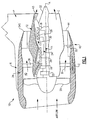
- FIG. 1 illustrates a general partial fragmentary schematic view of a gas turbofan engine 10 suspended from an engine pylon P within an engine nacelle assembly N.
- the turbofan engine 10 includes a core engine within a core nacelle 12 that houses a low spool 14 and high spool 24.
- the low spool 14 includes a low pressure compressor 16 and low pressure turbine 18.
- the low spool 14 also drives a fan section 20 through a geared architecture 22.
- the high spool 24 includes a high pressure compressor 26 and high pressure turbine 28.
- a combustor 30 is arranged between the high pressure compressor 26 and high pressure turbine 28.
- the low and high spools 14, 24 rotate about an engine axis of rotation A.
- the engine 10 in one non-limiting embodiment is a bypass geared architecture aircraft engine with a high bypass ratio and a turbofan diameter significantly larger than that of the low pressure compressor 16.
- the geared architecture 22 may be an epicycle gear train such as a planetary gear system or other gear system with a gear reduction ratio of greater than 2.5:1. It should be understood, however, that the above parameters are only exemplary of one non-limiting embodiment of a geared architecture engine and that this disclosure is applicable to other gas turbine engines including direct drive turbofans.
- Core airflow compressed by the low pressure compressor 16 and the high pressure compressor 26 is mixed with the fuel in the combustor 30 and expanded over the high pressure turbine 28 and low pressure turbine 18.
- the turbines 28, 18 are coupled for rotation with respective spools 24, 14 to rotationally drive the compressors 26, 16 and through the gear train 22, the fan section 20 in response to the expansion.
- the core nacelle 12 is supported within the fan nacelle 34 by circumferentially spaced structures 36 often referred to as Fan Exit Guide Vanes (FEGVs).
- a bypass flow path 40 is defined between the core nacelle 12 and the fan nacelle 34.
- the engine 10 generates a high bypass flow arrangement with a bypass ratio in which a large portion of the airflow which enters the fan nacelle 34 becomes bypass flow B.
- the bypass flow B communicates through the generally annular bypass flow path 40 and is discharged from the engine 10 through a variable area fan nozzle (VAFN) 42 which defines a nozzle exit area 44 between the fan nacelle 34 and the core nacelle 12 at a fan nacelle trailing edge 34S of the fan nacelle 34 downstream of the fan section 20.
- VAFN variable area fan nozzle
- Thrust is a function of density, velocity, and area. One or more of these parameters can be manipulated to vary the amount and direction of thrust provided by the bypass flow B.
- the VAFN 42 operates to effectively vary the area of the fan nozzle exit area 44 to selectively adjust the mass flow of the bypass flow B in response to a controller C.
- Low pressure ratio turbofans are desirable for their high propulsive efficiency. However, low pressure ratio fans may be inherently susceptible to fan stability/flutter problems at low power and low flight speeds.
- the VAFN 42 allows the engine to change to a more favorable fan operating line at low power, avoiding the instability region and still provide the relatively smaller nozzle area necessary to obtain a high-efficiency fan operating line at cruise speeds.
- the fan section 20 of the engine 10 is designed for a particular flight condition -- typically cruise at 0.8M and 35,000 feet.
- the VAFN 42 is operated to effectively vary the fan nozzle exit area 44 to adjust fan bypass air flow such that the angle of attack or incidence on the fan blades is maintained close to the design incidence for efficient engine operation at other flight conditions, such as landing and takeoff to thus provide optimized engine operation over a range of flight conditions with respect to performance and other operational parameters such as noise levels.
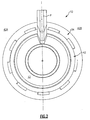
- the VAFN 42 may be separated into at least two sectors 42A-42B ( Figure 2 ) defined between the pylon P and a lower Bi-Fi splitter which may interconnect a larger diameter fan duct reverser cowl and a smaller diameter core cowl. It should be understood that although two segments are illustrated, any number of sectors may alternatively or additionally be provided.
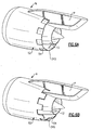
- the VAFN 42 selectively defines an auxiliary port system 50 with a first fan nacelle section 52 and a second fan nacelle section 54 rotationally mounted relative the first fan nacelle section 52.
- the first fan nacelle section 52 at least partially defines the fan nacelle trailing edge 34S with an intermittent trailing edge 60.
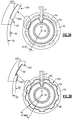
- the intermittent trailing edge 60 in one disclosed non-limiting embodiment provides a saw-tooth edge which forms a multiple of ports 62 ( Figure 3B ).
- Each of the multiple of ports 62 has a port trailing edge 62S axially forward of the fan nacelle trailing edge 34S.
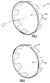
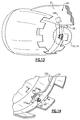
- the second fan nacelle section 54 in one non-limiting embodiment, includes circular ring portion 64 with a multiple of doors 66 which extend therefrom and match the multiple of ports 62.
- Each of the multiple of doors 66 has a door trailing edge 66S aligned with the fan nacelle trailing edge 34S ( Figure 6A ). It should be understood that although the multiple of ports 62 and the multiple of doors 66 in the illustrated embodiment are generally rectilinear, other shapes or combinations of various shapes may alternatively be provided.
- the second fan nacelle section 54' may be defined by two semi-ring portions ( Figure 5 ) which correspond with the respective sectors 42A-42B ( Figure 2 ) defined between the pylon P and the lower Bi-Fi splitter L.
- the semi-ring portions of the second fan nacelle section 54' may facilitate rotational movement thereof.
- the second fan nacelle section 54 is selectively translatable about the engine axis A relative the fixed first fan nacelle section 52 to change the effective area of the fan nozzle exit area 44 through selective opening of the ports 62. That is, the second fan nacelle section 54 may, in one non-limiting embodiment, rotate or otherwise move about the engine axis A. As the second fan nacelle section 54 selectively translates about the engine axis A, the ports 62 are either closed by the doors 66 in the second fan nacelle section 54 ( Figure 6A ) or are opened by offset of the second fan nacelle section 54 relative the ports 62 ( Figure 6B ).
- each of the multiple of doors 66 match each of the multiple of ports 62 such that the fan nacelle trailing edge 34S is continuous when the second fan nacelle section 54 is selectively translated to the closed position relative the fixed first fan nacelle section 52 ( Figure 6A ).
- the second fan nacelle section 54 is illustrated in the disclosed non-limiting embodiment as being rotatable, relative the fixed first fan nacelle section 52, it should be understood that other translatable movement may alternatively or additionally be provided.
- the VAFN 42 communicates with the controller C to selectively translate about the engine axis A the second fan nacelle section 54 relative the first fan nacelle section 52 through an actuator system 70 to change the fan nozzle exit area 44.
- various control systems including an engine controller or an aircraft flight control system may also be usable with the present application.
- the VAFN 42 changes the physical area and geometry of the bypass flow path 40 during particular flight modes to accommodate optimum conditions for the engine such as the Fan Pressure Ratio (FPR) that is varied in response to particular flight modes.
- FPR Fan Pressure Ratio
- the bypass flow B is effectively altered by rotation of the second fan nacelle section 54 relative the first fan nacelle section 52 between a closed position ( Figures 3A and 6A ) and an open position ( Figures 3B and 6B ).
- Rotation of the second fan nacelle section 54 to close the multiple of ports 62 of the auxiliary port system 60 decrease the fan nozzle exit area 44 toward exit area R1.
- Rotation of the second fan nacelle section 54 to open the ports 62 opens the auxiliary port system 60 to increase the fan nozzle exit area 44 toward exit area R2. That is, exit area R2 is greater than exit area R1.
- an interface 68 between the second fan nacelle section 54 and the first fan nacelle section 52 includes a ring flange 72 of the circular ring portion 64 which is rotationally trapped between the first fan nacelle section 52 and a fairing 74 attached to the first fan nacelle section 52.
- the fairing 74 defines an outer aerodynamic surface for the bypass flow B.
- the fairing 74 includes a radial fairing flange 76 and the first fan nacelle section 52 includes a radial nacelle flange 78 between which the ring flange 72 is slidably located.
- the ring flange 72 extends in an inboard direction while the radial fairing flange 76 and the radial nacelle flange 78 extend in an outboard direction relative the axis A. It should be understood that various friction reduction elements such as bearing and slider surfaces may additionally be provided.
- one non-limiting embodiment of the actuator system 70A includes a gear rack 80 on the second fan nacelle section 54 which meshes with a pinion gear 82.
- a slot 74S in the fairing 74 provides access to the gear rack 80.
- the pinion gear 82 is translated by an actuator 84 such as a hydraulic, electric or pneumatic drive.
- the actuator 84 may alternatively be positioned within the first fan nacelle section 52 such that the actuator 84 is within the outer aerodynamic surface which bounds the bypass flow B. Rotation of the pinion gear 82 drives the gear rack 80 and thereby position the fan nacelle section 54 relative to the first fan nacelle section 52 between a closed position and an open position ( Figures 6A and 6B ).
- FIG. 11 another non-limiting embodiment of the actuator system 70B includes a mount 86 on the second fan nacelle section 54" ( Figure 12 ) which is directly actuated. That is, the mount 86 receives, for example, a push/pull input by an actuator 88 such as a linear actuator to position the fan nacelle section 54 relative to the first fan nacelle section 52 between a closed position and an open position ( Figures 6A and 6B ).
- a slot 74S in the fairing 74 provides access for the mount 86.
- the actuator 88 is illustrated schematically and may alternatively be positioned within the first fan nacelle section 52 such that the actuator 88 is within the outer aerodynamic surface which bounds the bypass flow B.
- FIG. 13 another non-limiting embodiment of the actuator system 70C, includes a gear rack 90 on the second fan nacelle section 54 meshes with a pinion gear 92 driven by a gear system 94 ( figure 14 ).
- the gear system may include a pinion gear 96 on a common shaft 100 with the pinion gear 92 such that a worm gear 98 drives the pinion gear 96 ( Figures 15 and 16 ).
- the worm gear 94 is remotely driven through a flexible shaft 102 powered by an actuator 104 such as a hydraulic, electric or pneumatic drive.
- the flexible shaft 102 facilitates location of the actuator 104 in a remote location such as within the engine pylon P. Rotation of the flexible shaft 102 by the actuator 104 drives the worm gear 98.
- the worm gear drives the pinion gear 96 to drive the pinion gear 92 and thus the gear rack 90 to thereby position the fan nacelle section 54 relative to the first fan nacelle section 52 between a closed position and an open position ( Figures 6A and 6B ).
Landscapes
- Engineering & Computer Science (AREA)
- Chemical & Material Sciences (AREA)
- Combustion & Propulsion (AREA)
- Mechanical Engineering (AREA)
- General Engineering & Computer Science (AREA)
- Structures Of Non-Positive Displacement Pumps (AREA)
- Control Of Turbines (AREA)
Claims (12)
- Ensemble de nacelle (N) pour un moteur à turbine à gaz comprenant :une nacelle centrale (12) définie autour d'un axe de ligne centrale de moteur (A) ;une nacelle de ventilateur (34) montée au moins en partie autour de ladite nacelle centrale (12) pour définir une voie de flux de dérivation de ventilateur (40) ;une buse de ventilateur à zone variable (42) en communication avec ladite voie de flux de dérivation de ventilateur (40), ladite buse de ventilateur à zone variable (42) présentant une première section de nacelle de ventilateur (52) et une seconde section de nacelle de ventilateur (54), ladite première section de nacelle de ventilateur (52) définissant une arête arrière intermittente (60) qui définit de multiples orifices (62) et ladite seconde section de nacelle de ventilateur (54) définit de multiples portes (66), chacune desdites multiples portes (66) correspondant à chacun desdits multiples orifices (62) de sorte qu'une arête arrière de nacelle de ventilateur (34S) soit continue lorsque ladite seconde section de nacelle de ventilateur (54) est sélectivement translatée à une position fermée par rapport à ladite première section de nacelle de ventilateur (52) ; etun système actionneur (70A ; 70B ; 70C) utilisable pour translater ladite seconde section de nacelle de ventilateur (54) par rapport à ladite première section de nacelle de ventilateur (52) à ladite position fermée ;caractérisé en ce qu'il comprend en outre :une interface (68) entre ladite première section de nacelle de ventilateur (52) et ladite seconde section de nacelle de ventilateur (54), ladite interface incluant un carénage (74) définissant une surface aérodynamique extérieure du flux de dérivation de ventilateur et une bride annulaire (72) d'une partie annulaire circulaire (64) de ladite seconde section de nacelle de ventilateur (54), piégée en rotation entre ladite première section de nacelle de ventilateur (52) et ledit carénage (74) ;ledit carénage (74) présentant une bride de carénage radiale (76), et ladite première section de nacelle de ventilateur (52) présentant une bride de nacelle radiale (78), entre lesquelles ladite bride annulaire (72) est située de manière coulissante, ledit carénage (74) présentant en outre une fente (74S) fournissant un accès à ou pour un composant (80 ; 86 ; 90) du système actionneur sur la seconde section de nacelle de ventilateur (54).
- Ensemble selon la revendication 1, dans lequel ladite première section de nacelle de ventilateur (52) et ladite seconde nacelle de ventilateur (54) définissent ladite arête arrière de nacelle de ventilateur (34S).
- Ensemble selon la revendication 1 ou 2, dans lequel chacun desdits multiples orifices (62) définit une arête arrière d'orifice (62S) axialement à l'avant d'une arête arrière de nacelle de ventilateur de ladite première section de nacelle de ventilateur (52), chacune desdites multiples portes (66) définit une arête arrière de porte (66S) alignée sur une arête arrière de nacelle de ventilateur (34S) de ladite première section de nacelle de ventilateur (52), ladite seconde section de nacelle de ventilateur (54) étant translatable par rapport à ladite première section de nacelle de ventilateur (52) entre ladite position fermée, dans laquelle lesdits multiples orifices (62) sont fermés par lesdites multiples portes (66) et une position ouverte, dans laquelle lesdites multiples portes (66) recouvrent au moins en partie ladite arête arrière intermittente (60) de sorte que lesdits multiples orifices (62) soient au moins en partie ouverts.
- Ensemble selon la revendication 1, 2 ou 3, dans lequel ladite première section de nacelle de ventilateur (52) définit une arête arrière en dent de scie de ladite nacelle de ventilateur (34).
- Ensemble selon une quelconque revendication précédente, dans lequel chacun desdits multiples orifices (62) est rectiligne.
- Ensemble selon une quelconque revendication précédente, dans lequel chacun desdits multiples orifices (62) définit une arête arrière à l'avant de ladite arête arrière de nacelle de ventilateur (34S).
- Ensemble selon une quelconque revendication précédente, dans lequel ladite seconde section de nacelle de ventilateur (54) est montée en rotation par rapport à ladite première section de nacelle de ventilateur (52).
- Moteur à turbine à gaz (10) comprenant :un moteur central définit autour d'un axe ;un turboventilateur (20) monté autour dudit axe ; etun ensemble de nacelle selon une quelconque revendication précédente ;ladite nacelle centrale étant définie au moins en partie autour dudit moteur central.
- Moteur à turbine à gaz selon la revendication 8, dans lequel ladite seconde section de nacelle de ventilateur (54') comprend deux parties annulaires qui correspondent à deux secteurs définis entre un pylône de moteur (P) et un répartiteur Bi-Fi inférieur.
- Procédé de variation de la buse de ventilateur à zone variable d'un moteur à turbine à gaz selon la revendication 8, comprenant :la translation sélective de la seconde section de nacelle de ventilateur (54) par rapport à la première section de nacelle de ventilateur (52) de sorte que l'arête arrière de nacelle de ventilateur (34S) soit continue lorsque la seconde section de nacelle de ventilateur (54) est dans une position fermée et soit intermittente lorsqu'elle est dans une position ouverte.
- Procédé selon la revendication 10, comprenant en outre :le maintien d'une arête arrière (66S) de chacune des multiples portes (66) en ligne sur une arête arrière de la première section de nacelle de ventilateur (52).
- Procédé selon la revendication 10 ou 11, comprenant en outre :la correspondance de la forme de chacune des multiples portes (66) à chacun des multiples orifices (62).
Applications Claiming Priority (1)
| Application Number | Priority Date | Filing Date | Title |
|---|---|---|---|
| US12/909,793 US8549834B2 (en) | 2010-10-21 | 2010-10-21 | Gas turbine engine with variable area fan nozzle |
Publications (3)
| Publication Number | Publication Date |
|---|---|
| EP2444645A2 EP2444645A2 (fr) | 2012-04-25 |
| EP2444645A3 EP2444645A3 (fr) | 2013-08-21 |
| EP2444645B1 true EP2444645B1 (fr) | 2016-05-04 |
Family
ID=44862637
Family Applications (1)
| Application Number | Title | Priority Date | Filing Date |
|---|---|---|---|
| EP11186217.3A Active EP2444645B1 (fr) | 2010-10-21 | 2011-10-21 | Moteur à turbine à gaz doté d'une tuyère variable de soufflante et procédé de fonctionnement d'une tuyère variable de soufflante |
Country Status (2)
| Country | Link |
|---|---|
| US (1) | US8549834B2 (fr) |
| EP (1) | EP2444645B1 (fr) |
Families Citing this family (13)
| Publication number | Priority date | Publication date | Assignee | Title |
|---|---|---|---|---|
| FR2958910B1 (fr) * | 2010-04-20 | 2012-04-27 | Aircelle Sa | Nacelle pour moteur d'aeronef a tuyere de section variable |
| US8979484B2 (en) | 2012-01-05 | 2015-03-17 | Pratt & Whitney Canada Corp. | Casing for an aircraft turbofan bypass engine |
| FR2996258B1 (fr) * | 2012-10-01 | 2014-10-17 | Snecma | Melangeur a rotation alternative pour tuyere a flux confluents de turbomachine et son procede de pilotage |
| US9989009B2 (en) | 2012-10-31 | 2018-06-05 | The Boeing Company | Methods and apparatus for sealing variable area fan nozzles of jet engines |
| US20160017815A1 (en) * | 2013-03-12 | 2016-01-21 | United Technologies Corporation | Expanding shell flow control device |
| EP3036422B1 (fr) | 2013-08-23 | 2023-04-12 | Raytheon Technologies Corporation | Tuyère convergente-divergente à hautes performances |
| WO2016000673A1 (fr) | 2014-06-30 | 2016-01-07 | Rudolf Ganz | Tuyère à chevrons |
| GB201609071D0 (en) * | 2016-05-24 | 2016-07-06 | Rolls Royce Plc | Aircraft gas turbine engine nacelle |
| US10641208B2 (en) * | 2017-11-27 | 2020-05-05 | Rohr, Inc. | Translating nozzle for mixed flow turbofan engine |
| GB201810888D0 (en) * | 2018-07-03 | 2018-08-15 | Rolls Royce Plc | Gas turbine engine fan arrangement |
| US11440671B2 (en) * | 2019-01-24 | 2022-09-13 | Amazon Technologies, Inc. | Adjustable motor fairings for aerial vehicles |
| CN114087087B (zh) * | 2021-10-29 | 2023-03-31 | 南京航空航天大学 | 一种多原理多模态气动矢量喷管及控制方法 |
| US11828248B1 (en) * | 2022-06-27 | 2023-11-28 | Pratt & Whitney Canada Corp. | Rotatably driven exhaust mixer |
Family Cites Families (101)
| Publication number | Priority date | Publication date | Assignee | Title |
|---|---|---|---|---|
| US2980199A (en) | 1956-03-16 | 1961-04-18 | Rolls Royce | Variable area jet propulsion nozzles |
| US2934966A (en) | 1957-11-12 | 1960-05-03 | Westinghouse Electric Corp | Control apparatus |
| GB1125268A (en) | 1967-01-12 | 1968-08-28 | Rolls Royce | Thrust spoiling and silencing in a gas turbine engine |
| GB1350895A (en) | 1970-07-31 | 1974-04-24 | Secr Defence | Jet efflux deflector |
| US3724759A (en) | 1971-12-02 | 1973-04-03 | Rohr Industries Inc | Drive mechanism |
| GB1418905A (en) | 1972-05-09 | 1975-12-24 | Rolls Royce | Gas turbine engines |
| US3779010A (en) | 1972-08-17 | 1973-12-18 | Gen Electric | Combined thrust reversing and throat varying mechanism for a gas turbine engine |
| US4132068A (en) | 1975-04-30 | 1979-01-02 | The United States Of America As Represented By The United States National Aeronautics And Space Administration | Variable area exhaust nozzle |
| US4068469A (en) | 1975-05-29 | 1978-01-17 | The United States Of America As Represented By The Administrator Of The National Aeronautics And Space Administration | Variable thrust nozzle for quiet turbofan engine and method of operating same |
| US4044973A (en) | 1975-12-29 | 1977-08-30 | The Boeing Company | Nacelle assembly and mounting structures for a turbofan jet propulsion engine |
| US4147027A (en) | 1976-04-06 | 1979-04-03 | Grumman Aerospace Corporation | Thrust reverser nozzle |
| US4205813A (en) | 1978-06-19 | 1980-06-03 | General Electric Company | Thrust vectoring apparatus for a VTOL aircraft |
| US4505443A (en) | 1978-12-29 | 1985-03-19 | General Dynamics Corporation | Propulsion system for a V/STOL airplane |
| US4301980A (en) | 1978-12-29 | 1981-11-24 | General Dynamics Corporation | Propulsion system for a V/STOL airplane |
| GB2043786B (en) | 1979-03-10 | 1983-01-12 | Rolls Royce | Gas turbine engine power plant |
| US4409788A (en) | 1979-04-23 | 1983-10-18 | General Electric Company | Actuation system for use on a gas turbine engine |
| US4291782A (en) | 1979-10-30 | 1981-09-29 | The Boeing Company | Simplified method and apparatus for hot-shield jet noise suppression |
| US4410150A (en) | 1980-03-03 | 1983-10-18 | General Electric Company | Drag-reducing nacelle |
| US5694767A (en) | 1981-11-02 | 1997-12-09 | General Electric Company | Variable slot bypass injector system |
| US4466587A (en) | 1981-12-21 | 1984-08-21 | General Electric Company | Nacelle installation |
| US5107675A (en) | 1983-03-18 | 1992-04-28 | Rolls-Royce Limited | Gas turbine engine |
| FR2622929A1 (fr) | 1987-11-05 | 1989-05-12 | Hispano Suiza Sa | Inverseur de poussee de turboreacteur a grilles,a section variable d'ejection |
| US4922712A (en) | 1988-03-28 | 1990-05-08 | General Electric Company | Thrust reverser for high bypass turbofan engine |
| GB8811698D0 (en) | 1988-05-18 | 1988-10-05 | Dowty Defence & Air Systems Lt | Hydraulic actuator system |
| US5201800A (en) | 1990-02-26 | 1993-04-13 | General Electric Company | Method for discharging combustion gases from an exhaust nozzle |
| US5261605A (en) | 1990-08-23 | 1993-11-16 | United Technologies Corporation | Axisymmetric nozzle with gimbled unison ring |
| US5082182A (en) | 1990-08-23 | 1992-01-21 | United Technologies Corporation | Thrust vectoring exhaust nozzle |
| US5120005A (en) | 1990-09-14 | 1992-06-09 | General Electric Company | Exhaust flap speedbrake |
| US5150839A (en) | 1991-03-14 | 1992-09-29 | General Electric Company | Nozzle load management |
| DE69232222T2 (de) | 1991-05-16 | 2002-08-22 | Gen Electric | Hitzeschild für achsymmetrische schwenkbare Schubdüse |
| FR2676779B1 (fr) | 1991-05-21 | 1994-06-03 | Lair Jean Pierre | Tuyere a section variable. |
| US5181676A (en) | 1992-01-06 | 1993-01-26 | Lair Jean Pierre | Thrust reverser integrating a variable exhaust area nozzle |
| ES2075782B1 (es) | 1992-02-20 | 1998-03-16 | Sener Ing & Sist | Tobera orientable de geometria variable para turbinas de gas. |
| US5261227A (en) | 1992-11-24 | 1993-11-16 | General Electric Company | Variable specific thrust turbofan engine |
| FR2698409B1 (fr) | 1992-11-25 | 1994-12-23 | Snecma | Tuyère d'éjection de turboréacteur. |
| US5315821A (en) | 1993-02-05 | 1994-05-31 | General Electric Company | Aircraft bypass turbofan engine thrust reverser |
| US5778659A (en) | 1994-10-20 | 1998-07-14 | United Technologies Corporation | Variable area fan exhaust nozzle having mechanically separate sleeve and thrust reverser actuation systems |
| FR2727468B1 (fr) | 1994-11-30 | 1996-12-27 | Hispano Suiza Sa | Inverseur de poussee de turboreacteur a obstacles aval |
| GB9424495D0 (en) | 1994-12-05 | 1995-01-25 | Short Brothers Plc | Aerodynamic low drag structure |
| US5655360A (en) | 1995-05-31 | 1997-08-12 | General Electric Company | Thrust reverser with variable nozzle |
| FR2737256B1 (fr) | 1995-07-26 | 1997-10-17 | Aerospatiale | Turboreacteur a double flux a portes d'inversion de poussee non soumises au flux secondaire dans leur position inactive |
| DE69514224T2 (de) | 1995-09-13 | 2000-08-10 | Hurel Dubois Avions | Elektrohydraulische Schubumkehrvorrichtung mit zwei Klappen |
| FR2741910B1 (fr) | 1995-11-30 | 1998-01-02 | Hispano Suiza Sa | Inverseur de poussee de turboreacteur a portes a panneau arriere articule |
| FR2742482B1 (fr) | 1995-12-19 | 1998-02-06 | Hurel Dubois Avions | Inverseur de poussee a tuyere a section reglable pour moteur d'avion a reaction |
| US5685141A (en) | 1995-12-26 | 1997-11-11 | General Electric Company | Lock for nozzle control in the event of hydraulic failure |
| GB2308866B (en) | 1996-01-04 | 1999-09-08 | Rolls Royce Plc | Ducted fan gas turbine engine with secondary duct |
| US5826823A (en) | 1996-02-07 | 1998-10-27 | Rohr, Inc. | Actuator and safety lock system for pivoting door thrust reverser for aircraft jet engine |
| DE69616739T2 (de) | 1996-02-08 | 2002-09-05 | Hurel Dubois Avions | Dichtungsanordnung für schwenkbare Schubumkehrklappe |
| US5806302A (en) | 1996-09-24 | 1998-09-15 | Rohr, Inc. | Variable fan exhaust area nozzle for aircraft gas turbine engine with thrust reverser |
| US5833140A (en) | 1996-12-12 | 1998-11-10 | United Technologies Corporation | Variable geometry exhaust nozzle for a turbine engine |
| FR2757215B1 (fr) | 1996-12-12 | 1999-01-22 | Hispano Suiza Sa | Inverseur de poussee de turboreacteur a portes comportant des aubes deflectrices associees a la structure fixe |
| EP0852290A1 (fr) | 1996-12-19 | 1998-07-08 | SOCIETE DE CONSTRUCTION DES AVIONS HUREL-DUBOIS (société anonyme) | Inverseur de poussée de turboréacteur à double flux avec grand taux de dilution |
| ES2136528B1 (es) | 1996-12-26 | 2000-05-01 | Sener Ing & Sist | Perfeccionamientos en toberas axisimetricas de geometria variable y orientacion del flujo destinadasa propulsores de turbina de gas |
| US5779152A (en) | 1997-01-16 | 1998-07-14 | General Electric Company | Coordinated vectoring exhaust nozzle with scissors linkage |
| DE69704479T2 (de) | 1997-01-17 | 2001-10-18 | Turbo Propulsores Ind | Dichtungsklappe für eine convergent-divergente Schubdüse |
| FR2760047B1 (fr) | 1997-02-27 | 1999-05-07 | Hispano Suiza Sa | Inverseur de poussee de turboreacteur a portes associees a un dispositif de synchronisation de commande |
| US5875995A (en) | 1997-05-20 | 1999-03-02 | Rohr, Inc. | Pivoting door type thrust reverser with deployable members for efflux control and flow separation |
| EP0886061B1 (fr) | 1997-06-16 | 2003-10-08 | Industria de Turbo Propulsores, S.A. | Ensemble de montage pour un volet maítre divergent pour tuyère à géométrie variable |
| US6212877B1 (en) | 1998-09-04 | 2001-04-10 | General Electric Company | Vectoring ring support and actuation mechanism for axisymmetric vectoring nozzle with a universal joint |
| GB9825651D0 (en) | 1998-11-23 | 1999-01-13 | Lucas Ind Plc | Actuator |
| FR2792367B1 (fr) | 1999-04-15 | 2002-04-26 | Snecma | Tuyere d'ejection axisymetrique, convergente divergente a orientation par un anneau guide |
| EP1052395B1 (fr) | 1999-05-13 | 2004-07-07 | Industria de Turbo Propulsores S.A. | Dispositif de commande de la section de sortie d'une tuyère convergente-divergente |
| US6318070B1 (en) | 2000-03-03 | 2001-11-20 | United Technologies Corporation | Variable area nozzle for gas turbine engines driven by shape memory alloy actuators |
| US6340135B1 (en) | 2000-05-30 | 2002-01-22 | Rohr, Inc. | Translating independently mounted air inlet system for aircraft turbofan jet engine |
| US6439840B1 (en) | 2000-11-30 | 2002-08-27 | Pratt & Whitney Canada Corp. | Bypass duct fan noise reduction assembly |
| US6640537B2 (en) | 2000-12-18 | 2003-11-04 | Pratt & Whitney Canada Corp. | Aero-engine exhaust jet noise reduction assembly |
| GB2372779A (en) * | 2001-03-03 | 2002-09-04 | Rolls Royce Plc | Gas turbine engine nozzle with noise reducing tabs |
| GB0105349D0 (en) | 2001-03-03 | 2001-04-18 | Rolls Royce Plc | Gas turbine engine exhaust nozzle |
| US6415599B1 (en) | 2001-05-11 | 2002-07-09 | General Electric Company | Engine interface for axisymmetric vectoring nozzle |
| US6505706B2 (en) | 2001-06-14 | 2003-01-14 | Pratt & Whitney Canada Corp. | Exhaust flow guide for jet noise reduction |
| US6598386B2 (en) | 2001-10-16 | 2003-07-29 | Honeywell International, Inc. | Jet engine thrust reverser system having torque limited synchronization |
| EP1438494B1 (fr) | 2001-10-23 | 2017-01-04 | THE NORDAM GROUP, Inc. | Tuyere d'echappement variable confluente |
| US6748744B2 (en) | 2001-11-21 | 2004-06-15 | Pratt & Whitney Canada Corp. | Method and apparatus for the engine control of output shaft speed |
| US6983588B2 (en) * | 2002-01-09 | 2006-01-10 | The Nordam Group, Inc. | Turbofan variable fan nozzle |
| US6543224B1 (en) | 2002-01-29 | 2003-04-08 | United Technologies Corporation | System and method for controlling shape memory alloy actuators |
| EP1509447A4 (fr) | 2002-05-21 | 2010-07-21 | Nordam Group Inc | Buse de reacteur a double flux bifurquee |
| US6718752B2 (en) | 2002-05-29 | 2004-04-13 | The Boeing Company | Deployable segmented exhaust nozzle for a jet engine |
| US6769868B2 (en) | 2002-07-31 | 2004-08-03 | General Electric Company | Stator vane actuator in gas turbine engine |
| US6810656B2 (en) | 2002-12-12 | 2004-11-02 | Honeywell International, Inc. | Thrust reverser system power drive unit with dual sequential torque decoupler and method |
| US7010905B2 (en) * | 2003-02-21 | 2006-03-14 | The Nordam Group, Inc. | Ventilated confluent exhaust nozzle |
| US7055329B2 (en) | 2003-03-31 | 2006-06-06 | General Electric Company | Method and apparatus for noise attenuation for gas turbine engines using at least one synthetic jet actuator for injecting air |
| US6966175B2 (en) | 2003-05-09 | 2005-11-22 | The Nordam Group, Inc. | Rotary adjustable exhaust nozzle |
| US7043898B2 (en) | 2003-06-23 | 2006-05-16 | Pratt & Whitney Canada Corp. | Combined exhaust duct and mixer for a gas turbine engine |
| FR2857414B1 (fr) | 2003-07-08 | 2007-06-08 | Snecma Moteurs | Volet souple de tuyere a section variable de turbomachine |
| US7093793B2 (en) | 2003-08-29 | 2006-08-22 | The Nordam Group, Inc. | Variable cam exhaust nozzle |
| US7458221B1 (en) | 2003-10-23 | 2008-12-02 | The United States Of America As Represented By The Administrator Of The National Aeronautics And Space Administration | Variable area nozzle including a plurality of convexly vanes with a crowned contour, in a vane to vane sealing arrangement and with nonuniform lengths |
| US7093423B2 (en) | 2004-01-20 | 2006-08-22 | General Electric Company | Methods and apparatus for operating gas turbine engines |
| US7032835B2 (en) | 2004-01-28 | 2006-04-25 | United Technologies Corporation | Convergent/divergent nozzle with modulated cooling |
| US7216831B2 (en) | 2004-11-12 | 2007-05-15 | The Boeing Company | Shape changing structure |
| US7624567B2 (en) | 2005-09-20 | 2009-12-01 | United Technologies Corporation | Convergent divergent nozzle with interlocking divergent flaps |
| US8235325B2 (en) | 2005-10-04 | 2012-08-07 | United Technologies Corporation | Fan variable area nozzle positional measurement system |
| GB0608093D0 (en) | 2006-04-25 | 2006-05-31 | Short Brothers Plc | Variable area exhaust nozzle |
| US7721551B2 (en) | 2006-06-29 | 2010-05-25 | United Technologies Corporation | Fan variable area nozzle for a gas turbine engine fan nacelle |
| US20080028763A1 (en) | 2006-08-03 | 2008-02-07 | United Technologies Corporation | Thermal management system with thrust recovery for a gas turbine engine fan nacelle assembly |
| EP2115289B1 (fr) * | 2006-10-12 | 2015-03-25 | United Technologies Corporation | Moteur à turbine à gaz à tuyère de soufflante à section variable à segments rotatifs superposés |
| US8291689B2 (en) * | 2006-10-12 | 2012-10-23 | United Technologies Corporation | Corrugated core cowl for a gas turbine engine |
| US8286415B2 (en) | 2006-10-12 | 2012-10-16 | United Technologies Corporation | Turbofan engine having inner fixed structure including ducted passages |
| US8365515B2 (en) | 2006-10-12 | 2013-02-05 | United Technologies Corporation | Gas turbine engine with fan variable area nozzle, nacelle assembly and method of varying area of a fan nozzle |
| US7797944B2 (en) | 2006-10-20 | 2010-09-21 | United Technologies Corporation | Gas turbine engine having slim-line nacelle |
| US7721549B2 (en) | 2007-02-08 | 2010-05-25 | United Technologies Corporation | Fan variable area nozzle for a gas turbine engine fan nacelle with cam drive ring actuation system |
| US8127531B2 (en) | 2008-11-11 | 2012-03-06 | The Boeing Company | Radially translating fan nozzle nacelle |
-
2010
- 2010-10-21 US US12/909,793 patent/US8549834B2/en active Active
-
2011
- 2011-10-21 EP EP11186217.3A patent/EP2444645B1/fr active Active
Also Published As
| Publication number | Publication date |
|---|---|
| EP2444645A2 (fr) | 2012-04-25 |
| EP2444645A3 (fr) | 2013-08-21 |
| US8549834B2 (en) | 2013-10-08 |
| US20120096831A1 (en) | 2012-04-26 |
Similar Documents
| Publication | Publication Date | Title |
|---|---|---|
| EP2444645B1 (fr) | Moteur à turbine à gaz doté d'une tuyère variable de soufflante et procédé de fonctionnement d'une tuyère variable de soufflante | |
| EP2504553B1 (fr) | Assemblage de nacelle pour capot de buse de soufflante à section variable d'une turbine à gaz | |
| EP2354516B1 (fr) | Inverseur de poussée en cascade pouvant être translaté | |
| US8104261B2 (en) | Tri-body variable area fan nozzle and thrust reverser | |
| EP1978232B1 (fr) | Tuyère à section variable pour flux secondaire et inverseur de poussée | |
| EP2157305B1 (fr) | Turbine à gaz avec tuyère variable de la soufflante | |
| US8104262B2 (en) | Dual function cascade integrated variable area fan nozzle and thrust reverser | |
| EP2504552B1 (fr) | Rail de support pour buse de soufflante à section variable | |
| EP2420665B1 (fr) | Buse de ventilateur à zone variable | |
| EP2074319B1 (fr) | Moteur à turbine à gaz avec tuyère d'éjection variable, ensemble nacelle de ce moteur et procédé de fonctionnement correspondant | |
| EP2069630B1 (fr) | Agencement de nacelle et procédé associé | |
| EP2028359A2 (fr) | Moteur à turbine à gaz doté d'une tuyère de ventilateur à surface variable mobile axialement | |
| US20110120078A1 (en) | Variable area fan nozzle track | |
| US10378479B2 (en) | Variable effective area fan nozzle | |
| US20130145745A1 (en) | Gas turbine engine with fan variable area nozzle for low fan pressure ratio | |
| US20170167438A1 (en) | Gas Turbine Engine | |
| EP2798188A1 (fr) | Moteur à turbine à gaz avec buse à jet plat à section variable pour un rapport de pression de ventilateur faible | |
| US10167813B2 (en) | Gas turbine engine with fan variable area nozzle to reduce fan instability | |
| EP2798162A2 (fr) | Moteur à turbine à gaz équipé d'une buse à section variable pour un ventilateur | |
| WO2013141932A1 (fr) | Moteur à turbine à gaz équipé d'une buse à section variable de soufflante permettant un rapport de pression soufflante faible | |
| EP2798187A1 (fr) | Moteur à turbine à gaz équipé d'une buse à section variable pour un ventilateur afin de réduire l'instabilité du ventilateur |
Legal Events
| Date | Code | Title | Description |
|---|---|---|---|
| AK | Designated contracting states |
Kind code of ref document: A2 Designated state(s): AL AT BE BG CH CY CZ DE DK EE ES FI FR GB GR HR HU IE IS IT LI LT LU LV MC MK MT NL NO PL PT RO RS SE SI SK SM TR |
|
| AX | Request for extension of the european patent |
Extension state: BA ME |
|
| PUAI | Public reference made under article 153(3) epc to a published international application that has entered the european phase |
Free format text: ORIGINAL CODE: 0009012 |
|
| PUAL | Search report despatched |
Free format text: ORIGINAL CODE: 0009013 |
|
| AK | Designated contracting states |
Kind code of ref document: A3 Designated state(s): AL AT BE BG CH CY CZ DE DK EE ES FI FR GB GR HR HU IE IS IT LI LT LU LV MC MK MT NL NO PL PT RO RS SE SI SK SM TR |
|
| AX | Request for extension of the european patent |
Extension state: BA ME |
|
| RIC1 | Information provided on ipc code assigned before grant |
Ipc: F02K 1/06 20060101AFI20130712BHEP Ipc: F02K 1/09 20060101ALI20130712BHEP Ipc: F02K 3/06 20060101ALI20130712BHEP Ipc: F02K 1/48 20060101ALI20130712BHEP Ipc: F02K 1/76 20060101ALI20130712BHEP Ipc: F02K 1/38 20060101ALI20130712BHEP |
|
| 17P | Request for examination filed |
Effective date: 20140220 |
|
| RBV | Designated contracting states (corrected) |
Designated state(s): AL AT BE BG CH CY CZ DE DK EE ES FI FR GB GR HR HU IE IS IT LI LT LU LV MC MK MT NL NO PL PT RO RS SE SI SK SM TR |
|
| 17Q | First examination report despatched |
Effective date: 20150105 |
|
| GRAP | Despatch of communication of intention to grant a patent |
Free format text: ORIGINAL CODE: EPIDOSNIGR1 |
|
| INTG | Intention to grant announced |
Effective date: 20151124 |
|
| GRAS | Grant fee paid |
Free format text: ORIGINAL CODE: EPIDOSNIGR3 |
|
| GRAA | (expected) grant |
Free format text: ORIGINAL CODE: 0009210 |
|
| AK | Designated contracting states |
Kind code of ref document: B1 Designated state(s): AL AT BE BG CH CY CZ DE DK EE ES FI FR GB GR HR HU IE IS IT LI LT LU LV MC MK MT NL NO PL PT RO RS SE SI SK SM TR |
|
| REG | Reference to a national code |
Ref country code: GB Ref legal event code: FG4D |
|
| REG | Reference to a national code |
Ref country code: CH Ref legal event code: EP |
|
| REG | Reference to a national code |
Ref country code: AT Ref legal event code: REF Ref document number: 797124 Country of ref document: AT Kind code of ref document: T Effective date: 20160515 |
|
| REG | Reference to a national code |
Ref country code: IE Ref legal event code: FG4D |
|
| REG | Reference to a national code |
Ref country code: DE Ref legal event code: R096 Ref document number: 602011026117 Country of ref document: DE |
|
| REG | Reference to a national code |
Ref country code: NL Ref legal event code: MP Effective date: 20160504 |
|
| REG | Reference to a national code |
Ref country code: LT Ref legal event code: MG4D |
|
| REG | Reference to a national code |
Ref country code: CH Ref legal event code: PCOW Free format text: NEW ADDRESS: 10 FARM SPRINGS RD., FARMINGTON, CT 06032 (US) |
|
| RAP2 | Party data changed (patent owner data changed or rights of a patent transferred) |
Owner name: UNITED TECHNOLOGIES CORPORATION |
|
| PG25 | Lapsed in a contracting state [announced via postgrant information from national office to epo] |
Ref country code: NL Free format text: LAPSE BECAUSE OF FAILURE TO SUBMIT A TRANSLATION OF THE DESCRIPTION OR TO PAY THE FEE WITHIN THE PRESCRIBED TIME-LIMIT Effective date: 20160504 Ref country code: FI Free format text: LAPSE BECAUSE OF FAILURE TO SUBMIT A TRANSLATION OF THE DESCRIPTION OR TO PAY THE FEE WITHIN THE PRESCRIBED TIME-LIMIT Effective date: 20160504 Ref country code: LT Free format text: LAPSE BECAUSE OF FAILURE TO SUBMIT A TRANSLATION OF THE DESCRIPTION OR TO PAY THE FEE WITHIN THE PRESCRIBED TIME-LIMIT Effective date: 20160504 Ref country code: NO Free format text: LAPSE BECAUSE OF FAILURE TO SUBMIT A TRANSLATION OF THE DESCRIPTION OR TO PAY THE FEE WITHIN THE PRESCRIBED TIME-LIMIT Effective date: 20160804 |
|
| REG | Reference to a national code |
Ref country code: AT Ref legal event code: MK05 Ref document number: 797124 Country of ref document: AT Kind code of ref document: T Effective date: 20160504 |
|
| PG25 | Lapsed in a contracting state [announced via postgrant information from national office to epo] |
Ref country code: PT Free format text: LAPSE BECAUSE OF FAILURE TO SUBMIT A TRANSLATION OF THE DESCRIPTION OR TO PAY THE FEE WITHIN THE PRESCRIBED TIME-LIMIT Effective date: 20160905 Ref country code: ES Free format text: LAPSE BECAUSE OF FAILURE TO SUBMIT A TRANSLATION OF THE DESCRIPTION OR TO PAY THE FEE WITHIN THE PRESCRIBED TIME-LIMIT Effective date: 20160504 Ref country code: SE Free format text: LAPSE BECAUSE OF FAILURE TO SUBMIT A TRANSLATION OF THE DESCRIPTION OR TO PAY THE FEE WITHIN THE PRESCRIBED TIME-LIMIT Effective date: 20160504 Ref country code: GR Free format text: LAPSE BECAUSE OF FAILURE TO SUBMIT A TRANSLATION OF THE DESCRIPTION OR TO PAY THE FEE WITHIN THE PRESCRIBED TIME-LIMIT Effective date: 20160805 Ref country code: RS Free format text: LAPSE BECAUSE OF FAILURE TO SUBMIT A TRANSLATION OF THE DESCRIPTION OR TO PAY THE FEE WITHIN THE PRESCRIBED TIME-LIMIT Effective date: 20160504 Ref country code: HR Free format text: LAPSE BECAUSE OF FAILURE TO SUBMIT A TRANSLATION OF THE DESCRIPTION OR TO PAY THE FEE WITHIN THE PRESCRIBED TIME-LIMIT Effective date: 20160504 Ref country code: LV Free format text: LAPSE BECAUSE OF FAILURE TO SUBMIT A TRANSLATION OF THE DESCRIPTION OR TO PAY THE FEE WITHIN THE PRESCRIBED TIME-LIMIT Effective date: 20160504 |
|
| PG25 | Lapsed in a contracting state [announced via postgrant information from national office to epo] |
Ref country code: IT Free format text: LAPSE BECAUSE OF FAILURE TO SUBMIT A TRANSLATION OF THE DESCRIPTION OR TO PAY THE FEE WITHIN THE PRESCRIBED TIME-LIMIT Effective date: 20160504 |
|
| PG25 | Lapsed in a contracting state [announced via postgrant information from national office to epo] |
Ref country code: SK Free format text: LAPSE BECAUSE OF FAILURE TO SUBMIT A TRANSLATION OF THE DESCRIPTION OR TO PAY THE FEE WITHIN THE PRESCRIBED TIME-LIMIT Effective date: 20160504 Ref country code: EE Free format text: LAPSE BECAUSE OF FAILURE TO SUBMIT A TRANSLATION OF THE DESCRIPTION OR TO PAY THE FEE WITHIN THE PRESCRIBED TIME-LIMIT Effective date: 20160504 Ref country code: DK Free format text: LAPSE BECAUSE OF FAILURE TO SUBMIT A TRANSLATION OF THE DESCRIPTION OR TO PAY THE FEE WITHIN THE PRESCRIBED TIME-LIMIT Effective date: 20160504 Ref country code: RO Free format text: LAPSE BECAUSE OF FAILURE TO SUBMIT A TRANSLATION OF THE DESCRIPTION OR TO PAY THE FEE WITHIN THE PRESCRIBED TIME-LIMIT Effective date: 20160504 Ref country code: CZ Free format text: LAPSE BECAUSE OF FAILURE TO SUBMIT A TRANSLATION OF THE DESCRIPTION OR TO PAY THE FEE WITHIN THE PRESCRIBED TIME-LIMIT Effective date: 20160504 |
|
| REG | Reference to a national code |
Ref country code: DE Ref legal event code: R097 Ref document number: 602011026117 Country of ref document: DE |
|
| PG25 | Lapsed in a contracting state [announced via postgrant information from national office to epo] |
Ref country code: SM Free format text: LAPSE BECAUSE OF FAILURE TO SUBMIT A TRANSLATION OF THE DESCRIPTION OR TO PAY THE FEE WITHIN THE PRESCRIBED TIME-LIMIT Effective date: 20160504 Ref country code: AT Free format text: LAPSE BECAUSE OF FAILURE TO SUBMIT A TRANSLATION OF THE DESCRIPTION OR TO PAY THE FEE WITHIN THE PRESCRIBED TIME-LIMIT Effective date: 20160504 Ref country code: PL Free format text: LAPSE BECAUSE OF FAILURE TO SUBMIT A TRANSLATION OF THE DESCRIPTION OR TO PAY THE FEE WITHIN THE PRESCRIBED TIME-LIMIT Effective date: 20160504 Ref country code: BE Free format text: LAPSE BECAUSE OF FAILURE TO SUBMIT A TRANSLATION OF THE DESCRIPTION OR TO PAY THE FEE WITHIN THE PRESCRIBED TIME-LIMIT Effective date: 20160504 |
|
| PLBE | No opposition filed within time limit |
Free format text: ORIGINAL CODE: 0009261 |
|
| STAA | Information on the status of an ep patent application or granted ep patent |
Free format text: STATUS: NO OPPOSITION FILED WITHIN TIME LIMIT |
|
| 26N | No opposition filed |
Effective date: 20170207 |
|
| PG25 | Lapsed in a contracting state [announced via postgrant information from national office to epo] |
Ref country code: SI Free format text: LAPSE BECAUSE OF FAILURE TO SUBMIT A TRANSLATION OF THE DESCRIPTION OR TO PAY THE FEE WITHIN THE PRESCRIBED TIME-LIMIT Effective date: 20160504 |
|
| REG | Reference to a national code |
Ref country code: CH Ref legal event code: PL |
|
| PG25 | Lapsed in a contracting state [announced via postgrant information from national office to epo] |
Ref country code: MC Free format text: LAPSE BECAUSE OF FAILURE TO SUBMIT A TRANSLATION OF THE DESCRIPTION OR TO PAY THE FEE WITHIN THE PRESCRIBED TIME-LIMIT Effective date: 20160504 |
|
| REG | Reference to a national code |
Ref country code: DE Ref legal event code: R082 Ref document number: 602011026117 Country of ref document: DE Representative=s name: SCHMITT-NILSON SCHRAUD WAIBEL WOHLFROM PATENTA, DE |
|
| REG | Reference to a national code |
Ref country code: DE Ref legal event code: R082 Ref document number: 602011026117 Country of ref document: DE Representative=s name: SCHMITT-NILSON SCHRAUD WAIBEL WOHLFROM PATENTA, DE Ref country code: DE Ref legal event code: R081 Ref document number: 602011026117 Country of ref document: DE Owner name: UNITED TECHNOLOGIES CORP. (N.D.GES.D. STAATES , US Free format text: FORMER OWNER: UNITED TECHNOLOGIES CORPORATION, HARTFORD, CONN., US |
|
| REG | Reference to a national code |
Ref country code: IE Ref legal event code: MM4A |
|
| REG | Reference to a national code |
Ref country code: FR Ref legal event code: ST Effective date: 20170630 |
|
| PG25 | Lapsed in a contracting state [announced via postgrant information from national office to epo] |
Ref country code: FR Free format text: LAPSE BECAUSE OF NON-PAYMENT OF DUE FEES Effective date: 20161102 Ref country code: CH Free format text: LAPSE BECAUSE OF NON-PAYMENT OF DUE FEES Effective date: 20161031 Ref country code: LI Free format text: LAPSE BECAUSE OF NON-PAYMENT OF DUE FEES Effective date: 20161031 |
|
| PG25 | Lapsed in a contracting state [announced via postgrant information from national office to epo] |
Ref country code: LU Free format text: LAPSE BECAUSE OF NON-PAYMENT OF DUE FEES Effective date: 20161021 |
|
| PG25 | Lapsed in a contracting state [announced via postgrant information from national office to epo] |
Ref country code: IE Free format text: LAPSE BECAUSE OF NON-PAYMENT OF DUE FEES Effective date: 20161021 |
|
| PG25 | Lapsed in a contracting state [announced via postgrant information from national office to epo] |
Ref country code: HU Free format text: LAPSE BECAUSE OF FAILURE TO SUBMIT A TRANSLATION OF THE DESCRIPTION OR TO PAY THE FEE WITHIN THE PRESCRIBED TIME-LIMIT; INVALID AB INITIO Effective date: 20111021 Ref country code: CY Free format text: LAPSE BECAUSE OF FAILURE TO SUBMIT A TRANSLATION OF THE DESCRIPTION OR TO PAY THE FEE WITHIN THE PRESCRIBED TIME-LIMIT Effective date: 20160504 |
|
| PG25 | Lapsed in a contracting state [announced via postgrant information from national office to epo] |
Ref country code: MK Free format text: LAPSE BECAUSE OF FAILURE TO SUBMIT A TRANSLATION OF THE DESCRIPTION OR TO PAY THE FEE WITHIN THE PRESCRIBED TIME-LIMIT Effective date: 20160504 Ref country code: TR Free format text: LAPSE BECAUSE OF FAILURE TO SUBMIT A TRANSLATION OF THE DESCRIPTION OR TO PAY THE FEE WITHIN THE PRESCRIBED TIME-LIMIT Effective date: 20160504 Ref country code: IS Free format text: LAPSE BECAUSE OF FAILURE TO SUBMIT A TRANSLATION OF THE DESCRIPTION OR TO PAY THE FEE WITHIN THE PRESCRIBED TIME-LIMIT Effective date: 20160504 Ref country code: MT Free format text: LAPSE BECAUSE OF NON-PAYMENT OF DUE FEES Effective date: 20161031 |
|
| PG25 | Lapsed in a contracting state [announced via postgrant information from national office to epo] |
Ref country code: BG Free format text: LAPSE BECAUSE OF FAILURE TO SUBMIT A TRANSLATION OF THE DESCRIPTION OR TO PAY THE FEE WITHIN THE PRESCRIBED TIME-LIMIT Effective date: 20160504 |
|
| PG25 | Lapsed in a contracting state [announced via postgrant information from national office to epo] |
Ref country code: AL Free format text: LAPSE BECAUSE OF FAILURE TO SUBMIT A TRANSLATION OF THE DESCRIPTION OR TO PAY THE FEE WITHIN THE PRESCRIBED TIME-LIMIT Effective date: 20160504 |
|
| REG | Reference to a national code |
Ref country code: DE Ref legal event code: R081 Ref document number: 602011026117 Country of ref document: DE Owner name: RAYTHEON TECHNOLOGIES CORPORATION (N.D.GES.D.S, US Free format text: FORMER OWNER: UNITED TECHNOLOGIES CORP. (N.D.GES.D. STAATES DELAWARE), FARMINGTON, CONN., US |
|
| P01 | Opt-out of the competence of the unified patent court (upc) registered |
Effective date: 20230520 |
|
| PGFP | Annual fee paid to national office [announced via postgrant information from national office to epo] |
Ref country code: GB Payment date: 20230920 Year of fee payment: 13 |
|
| PGFP | Annual fee paid to national office [announced via postgrant information from national office to epo] |
Ref country code: DE Payment date: 20230920 Year of fee payment: 13 |