EP2444587B1 - Antriebsvorrichtung - Google Patents
Antriebsvorrichtung Download PDFInfo
- Publication number
- EP2444587B1 EP2444587B1 EP11006518.2A EP11006518A EP2444587B1 EP 2444587 B1 EP2444587 B1 EP 2444587B1 EP 11006518 A EP11006518 A EP 11006518A EP 2444587 B1 EP2444587 B1 EP 2444587B1
- Authority
- EP
- European Patent Office
- Prior art keywords
- drive
- vibration
- hollow shaft
- rotary
- rotary drive
- Prior art date
- Legal status (The legal status is an assumption and is not a legal conclusion. Google has not performed a legal analysis and makes no representation as to the accuracy of the status listed.)
- Active
Links
- 238000002347 injection Methods 0.000 claims description 11
- 239000007924 injection Substances 0.000 claims description 11
- 238000005553 drilling Methods 0.000 description 8
- 230000033001 locomotion Effects 0.000 description 7
- 238000010276 construction Methods 0.000 description 2
- 238000000034 method Methods 0.000 description 2
- 238000011001 backwashing Methods 0.000 description 1
- 230000005540 biological transmission Effects 0.000 description 1
- 230000008878 coupling Effects 0.000 description 1
- 238000010168 coupling process Methods 0.000 description 1
- 238000005859 coupling reaction Methods 0.000 description 1
- 230000001419 dependent effect Effects 0.000 description 1
- 239000007787 solid Substances 0.000 description 1
- 239000000725 suspension Substances 0.000 description 1
Images

Classifications
-
- E—FIXED CONSTRUCTIONS
- E21—EARTH OR ROCK DRILLING; MINING
- E21B—EARTH OR ROCK DRILLING; OBTAINING OIL, GAS, WATER, SOLUBLE OR MELTABLE MATERIALS OR A SLURRY OF MINERALS FROM WELLS
- E21B7/00—Special methods or apparatus for drilling
- E21B7/002—Drilling with diversely driven shafts extending into the borehole
-
- E—FIXED CONSTRUCTIONS
- E21—EARTH OR ROCK DRILLING; MINING
- E21B—EARTH OR ROCK DRILLING; OBTAINING OIL, GAS, WATER, SOLUBLE OR MELTABLE MATERIALS OR A SLURRY OF MINERALS FROM WELLS
- E21B6/00—Drives for drilling with combined rotary and percussive action
- E21B6/02—Drives for drilling with combined rotary and percussive action the rotation being continuous
-
- E—FIXED CONSTRUCTIONS
- E21—EARTH OR ROCK DRILLING; MINING
- E21B—EARTH OR ROCK DRILLING; OBTAINING OIL, GAS, WATER, SOLUBLE OR MELTABLE MATERIALS OR A SLURRY OF MINERALS FROM WELLS
- E21B7/00—Special methods or apparatus for drilling
- E21B7/24—Drilling using vibrating or oscillating means, e.g. out-of-balance masses
Definitions
- the invention relates to a drive device for driving a drill pipe according to the preamble of claim 1.
- a drive device comprises at least one rotary drive for rotationally driving the drill pipe, at least one vibration drive for generating a vibration at the drill pipe and at least one connection area for connecting the drill pipe to the drive device ,
- a drive device is for example from the WO 2009/014444 A1 known.
- the rotary drive is arranged from the perspective of the drill pipe behind the vibration drive and decoupled via a coupling of this.
- WO 2009/088176 A2 describes a vibratory hammer with a rotary drive, which comprises a rotary unit and a vibration unit. A piston is passed through the rotary unit and the vibration unit.
- DE 32 29 998 A1 discloses a drilling apparatus for overburden drilling with an inner pipe string connected to a rotary hammer and with an outer pipe string connected to a rotary drive.
- the rotary impact hammer comprises a hammer mechanism, with which a rear end of the inner pipe string can be subjected to impacts.
- the invention has for its object to provide a drive device for driving a drill pipe, which is particularly versatile and flexible.
- the rotary drive is arranged between the connection region and the vibration drive, that a hollow shaft is provided, which is rotationally driven by the rotary drive and vibratory driven by the vibration drive, and that the hollow shaft passes through the vibration drive and the rotary drive extends.
- the vibration drive which can also be referred to as a vibration cell, on the connection area opposite side of the drive device, ie behind the rotary drive to arrange.
- a transmission of the vibratory motion generated by the vibration drive through the rotary drive is expressly desired.
- a complete decoupling of the entire rotary drive from the vibration drive is not necessary.
- Another basic idea of the invention is to provide as the main shaft of the drive device a hollow shaft which extends through both the rotary drive and the vibration drive.
- the main or hollow shaft is vibrated by the vibration drive, ie in an oscillating motion.
- the vibration continues through the rotary drive up to the connection area.
- the hollow shaft is rotated by the rotary drive.
- a superposition of a vibration with a rotation is available at the connection area, which can be transferred to the drill pipe to be connected.
- the rotary drive can be designed not only for rotating but also for rotationally driven driving.
- the main shaft By executing the main shaft as a hollow shaft, a particularly versatile and compact drive device for a variety of drilling methods is provided.
- the drive device could in principle be used as a conventional single drive for driving a single drill string or drill pipe.
- the drive device is used as a double-head drive for driving an inner linkage and an outer linkage.
- the hollow shaft for use as a double-head drive is provided by the hollow shaft, the possibility to arrange a drill pipe through the rotary drive and the vibration drive through and to drive by means of a arranged behind the vibration drive further rotary drive rotating.
- the hollow shaft within the rotary drive Due to the vibration drive arranged behind the rotary drive, the hollow shaft within the rotary drive, as already shown, also exposed to vibration. So that the entire rotary drive including housing is not vibrated, in a preferred embodiment of the invention it is provided that the hollow shaft within the rotary drive, in particular within a housing of the rotary drive, is guided axially displaceable.
- the hollow shaft has an outer longitudinal toothing, which is in engagement with a toothing of a drive element of the rotary drive.
- the external longitudinal toothing preferably extends at least along an axial section of the hollow shaft, which is arranged within the rotary drive.
- the external longitudinal toothing preferably has a tooth profile.
- the tooth profile may include a plurality of teeth that extend annularly around the hollow shaft and each have a longitudinal axis that extends along a longitudinal axis of the hollow shaft.
- the teeth preferably have at least one length which corresponds to a maximum stroke of the hollow shaft.
- connection region comprises a connection device, which is arranged on an axial end of the hollow shaft facing the drilling tool to be connected.
- a connection device which is arranged on an axial end of the hollow shaft facing the drilling tool to be connected.
- connection device may have an adapter which is adapted to connect different types of drill pipe.
- the connection device may, for example, have a connection flange.
- At least two rotary drives are provided, wherein a first rotary drive is connected to the vibration drive to a vibration rotary unit and a further rotary drive is provided as a separate unit.
- the drive device can be used for example as a double-head drill drive.
- the individual Rotary actuators each provided for driving a single linkage, wherein an inner linkage and by the further rotary drive an outer linkage can be driven to rotate by one of the rotary drives.
- the further rotary drive is arranged behind the vibration drive.
- the vibration drive also allows the outer linkage to vibrate.
- the second rotary drive drives an inner linkage which extends from the second rotary drive through the vibration drive and the first rotary drive.
- the further rotary drive is arranged in front of the first rotary drive.
- the first rotary drive is thus located between the further rotary drive and the vibration drive.
- the further rotary drive has a passage for the inner rod.
- the further rotary drive preferably comprises a hollow shaft, through which the linkage driven by the first rotary drive can extend.
- the further rotary drive preferably comprises a connection region for connecting an external linkage.
- a further preferred embodiment of the invention is given by the fact that a high-pressure injection linkage (HDI linkage) can be arranged in the hollow shaft.
- the high pressure injection linkage may be provided with lateral injection nozzles at its front end.
- a backwashing head and / or a connection for a suspension feed can be provided.
- the flexibility and possible uses of the drive device can be further increased by the fact that the rotary drive and the vibration drive are detachably connected to each other. As a result, if appropriate, a further drive can be arranged between these two drives.
- the hollow shaft comprises a first hollow shaft section within the rotary drive and a second hollow shaft section within the vibration drive, wherein the first hollow shaft section and the second hollow shaft section are rotatably coupled to each other via an annular rotary connection.
- the hollow shaft can be made in one piece and extend through the vibration drive and the rotary drive through.
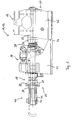
- Fig. 1 shows a drive device 10 according to the invention with a rotary drive 14 and a vibration drive 16.
- the drive device 10 is in particular adapted to drive a drill pipe 70 with a drilling tool provided thereon rotationally and oscillating.
- the drill string 70 may include an inner linkage 74, an outer linkage 76, and / or a high pressure injection linkage 72.
- the rotary drive 14 and the vibratory drive 16 are arranged on a mounting base 26 and fixedly connected to one another via this.
- the drive device with the rotary drive 14 and the vibration drive 16 can thus also be referred to as a vibratory rotary unit 12.
- the mounting base 26 is designed so that the vibration rotary unit 12 can be arranged on a carriage of a construction work tool, to be more accurate, can be.
- the mounting base 26 has corresponding fastening devices, for example a mounting flange. With the carriage, the vibration rotary unit 12 can be moved to perform drilling operations along a mast or Gurklers the construction equipment.
- the vibration rotary unit 12 includes a main shaft, which is designed as a hollow shaft 22.
- the hollow shaft 22 has a tubular opening and extends through both the entire rotary drive 14 and through the entire vibration drive 16 therethrough.
- the hollow shaft 22 can be driven in rotation by means of the rotary drive 14. To generate the rotational movement, the hollow shaft 22 is provided with an external longitudinal toothing, which can be coupled to a drive element of the rotary drive 14.
- the rotary drive 14 has a housing 40.
- the hollow shaft 22 is mounted axially displaceable within the rotary drive 14, in particular relative to the housing 40.
- an axial vibration on the hollow shaft 22 can be generated by the vibration drive 16.
- the vibration drive 16 has a vibration element 36, which is driven in a vibrating manner and firmly connected to the hollow shaft 22 for transmitting the vibration.
- a connecting flange For vibrating the vibrating element 36 with a connecting flange, it is possible, for example, to provide eccentric masses which are fastened off-center to counter-rotating shafts.
- the vibration element 36 and the hollow shaft 22 are mounted axially displaceable within a housing 42 of the vibration drive 16.
- the housing 42 of the vibratory drive 16 and the receptacle 40 of the rotary drive 14 are arranged spaced from each other. Between the housing 42 and the receptacle 40 or holder, the hollow shaft 22 is nevertheless completely enclosed to protect against external influences such as dirt. This is between the recording 40 and the housing 42, an enveloping element 38 is arranged.
- the vibration element 36 protrudes in the direction of the receptacle 40 of the rotary drive 14 out of the housing 42 of the vibration drive 16 and is connected via the enveloping element 38 with the housing-like receptacle 40 of the rotary drive 14.
- the enveloping element 38 surrounds the hollow shaft and is designed as a bellows in the illustrated embodiment. However, other types of enveloping element are possible.
- the vibratory rotary unit 12 has a front side 28 facing the drilling tool and a rear side 30 facing away from it. At the front side 28, a connection region 18 is provided, which has a connection device 20 for connecting a drill pipe 70.
- the connection device 20 is formed in the illustrated embodiment as a connection flange.
- the connection device 20 is coupled to the hollow shaft 22 of the vibration rotary unit 12, so that both the rotational movement and the vibration movement is provided on the connection device 20.
- the connection device 20 can be coupled to a drill pipe 70 or drill pipe.
- connection device 20 comprises a tubular part with a passage opening 21, which is connected to the tubular opening of the hollow shaft 22 and in particular coaxially aligned therewith.
- the connection device 20 can furthermore have an annular adapter 34, which is designed for the simultaneous holding or simultaneous connection of an inner linkage 74 and an outer linkage 76, as in FIG Fig. 1 shown.
- the adapter 34 may also be used to attach only one outer linkage 76, as in FIG Fig. 3 shown, or for fastening only an inner linkage 74, as in Fig. 4 represented, be formed.
- the adapter 34 also has a passage opening which is connected to the tubular opening of the hollow shaft 22 and in particular coaxially aligned therewith.
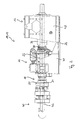
- Fig. 2 shows an embodiment of the invention in which within the hollow shaft 22, a high-pressure injection linkage 72 is arranged.
- the high pressure injection linkage 72 is passed through the entire hollow shaft 22 and protrudes beyond the axial end at both axial end.
- the high-pressure injection rod 72 is rotatably connected to the hollow shaft and secured axially.
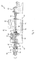
- Fig. 3 an embodiment of the invention is shown in which by means of the vibratory rotary unit 12, an outer rod 76 can be driven to rotate and vibrate.
- a further second rotary drive 50 is arranged on the rear side 30 of the vibration rotary unit 12.
- the second rotary drive 50 can be configured as a conventional rotary drive with a solid main shaft or as a rotary drive with a hollow shaft.
- the inner linkage 74 which can be driven by the second rotary drive 50 can extend through the entire hollow shaft 22 of the vibratory rotary unit 12 and further inside the outer linkage 76.
- the outer linkage 76 is thus rotationally and vibratory driven, while the inner linkage 74 is driven only rotationally.
- the inner linkage 74 is drivable in an opposite direction of rotation to the outer linkage 76 as in FIG Fig. 3 shown by the arcuate arrows.
- FIG. 4 Another embodiment of the invention is in Fig. 4 shown.
- the vibratory rotary unit 12 drives an inner rod 74 to rotate and vibrate.
- the inner rod 74 is connected via the connecting device 20 and the adapter 34 to the hollow shaft 22.
- a further rotary drive 60 is arranged, which is provided for the rotational driving of an outer linkage 76.
- the further rotary drive 60 has a main shaft designed as a hollow shaft 62, through which the inner linkage 74 driven by the vibratory rotary unit 12 can extend.
- the inner linkage 74 is thus rotationally and vibratory driven, while the outer linkage 76 is driven only rotationally.
- the direction of rotation of the inner linkage 74 may be opposite to the direction of rotation of the outer linkage 76, as in FIG Fig. 4 shown by the arcuate arrows.
Landscapes
- Life Sciences & Earth Sciences (AREA)
- Engineering & Computer Science (AREA)
- Geology (AREA)
- Mining & Mineral Resources (AREA)
- Physics & Mathematics (AREA)
- Environmental & Geological Engineering (AREA)
- Fluid Mechanics (AREA)
- General Life Sciences & Earth Sciences (AREA)
- Geochemistry & Mineralogy (AREA)
- Earth Drilling (AREA)
- Drilling And Boring (AREA)
Priority Applications (1)
| Application Number | Priority Date | Filing Date | Title |
|---|---|---|---|
| PL11006518T PL2444587T3 (pl) | 2010-10-19 | 2011-08-08 | Urządzenie napędowe |
Applications Claiming Priority (1)
| Application Number | Priority Date | Filing Date | Title |
|---|---|---|---|
| DE202010014478U DE202010014478U1 (de) | 2010-10-19 | 2010-10-19 | Antriebsvorrichtung |
Publications (2)
| Publication Number | Publication Date |
|---|---|
| EP2444587A1 EP2444587A1 (de) | 2012-04-25 |
| EP2444587B1 true EP2444587B1 (de) | 2014-02-26 |
Family
ID=43383238
Family Applications (1)
| Application Number | Title | Priority Date | Filing Date |
|---|---|---|---|
| EP11006518.2A Active EP2444587B1 (de) | 2010-10-19 | 2011-08-08 | Antriebsvorrichtung |
Country Status (3)
| Country | Link |
|---|---|
| EP (1) | EP2444587B1 (pl) |
| DE (1) | DE202010014478U1 (pl) |
| PL (1) | PL2444587T3 (pl) |
Cited By (2)
| Publication number | Priority date | Publication date | Assignee | Title |
|---|---|---|---|---|
| US10829996B2 (en) | 2018-02-13 | 2020-11-10 | Eurodrill Gmbh | Drilling device for earth or rock drilling and method for retrofitting such a drilling device |
| EP3867484A1 (de) * | 2018-10-18 | 2021-08-25 | BTR Bohrtechnik Rosswag GmbH & Co. KG | Verfahren und vorrichtung zum rückbau von erdwärmesonden |
Families Citing this family (3)
| Publication number | Priority date | Publication date | Assignee | Title |
|---|---|---|---|---|
| EP2634363B1 (de) | 2012-02-28 | 2015-09-09 | Eurodrill GmbH | Antriebsvorrichtung und Verfahren zum Antreiben eines Bohrgestänges |
| DK2772606T3 (en) | 2013-02-27 | 2015-04-27 | Eurodrill Gmbh | Drive device and method of operating a drive device |
| DE102019001201A1 (de) | 2019-02-20 | 2020-08-20 | TRACTO-TECHNlK GmbH & Co. KG | Erdbohrvorrichtung, System umfassend die Erdbohrvorrichtung, Verfahren zum Herstellen einer Erdbohrvorrichtung sowie Verwendung einer Erdbohrvorrichtung |
Family Cites Families (5)
| Publication number | Priority date | Publication date | Assignee | Title |
|---|---|---|---|---|
| DE2924392C2 (de) * | 1979-06-16 | 1982-09-23 | Brückner Grundbau GmbH, 4300 Essen | Bohrvorrichtung zum Überlagerungsbohren |
| DE3229998A1 (de) * | 1982-08-12 | 1984-02-16 | Ing. Günter Klemm, Spezialunternehmen für Bohrtechnik, 5962 Drolshagen | Bohrvorrichtung |
| US7347283B1 (en) * | 2002-01-15 | 2008-03-25 | The Charles Machine Works, Inc. | Using a rotating inner member to drive a tool in a hollow outer member |
| NL1034180C2 (nl) | 2007-07-24 | 2009-01-27 | Sonicsampdrill B V | Boorinrichting met rotatie-vibratie aandrijving. |
| JP5196506B2 (ja) * | 2008-01-07 | 2013-05-15 | シン イン,スク | バイブレーションハンマー |
-
2010
- 2010-10-19 DE DE202010014478U patent/DE202010014478U1/de not_active Expired - Lifetime
-
2011
- 2011-08-08 PL PL11006518T patent/PL2444587T3/pl unknown
- 2011-08-08 EP EP11006518.2A patent/EP2444587B1/de active Active
Cited By (2)
| Publication number | Priority date | Publication date | Assignee | Title |
|---|---|---|---|---|
| US10829996B2 (en) | 2018-02-13 | 2020-11-10 | Eurodrill Gmbh | Drilling device for earth or rock drilling and method for retrofitting such a drilling device |
| EP3867484A1 (de) * | 2018-10-18 | 2021-08-25 | BTR Bohrtechnik Rosswag GmbH & Co. KG | Verfahren und vorrichtung zum rückbau von erdwärmesonden |
Also Published As
| Publication number | Publication date |
|---|---|
| DE202010014478U1 (de) | 2010-12-16 |
| EP2444587A1 (de) | 2012-04-25 |
| PL2444587T3 (pl) | 2014-07-31 |
Similar Documents
| Publication | Publication Date | Title |
|---|---|---|
| DE3405922C2 (pl) | ||
| EP3261805B1 (de) | Handwerkzeugmaschine | |
| EP2444587B1 (de) | Antriebsvorrichtung | |
| EP1923176B1 (de) | Bohrhammer | |
| DE102008000516A1 (de) | Zusatzhandgriff sowie Handwerkzeugmaschine | |
| EP2123406A1 (de) | Vibrationsgedämpfter Halter für Zusatzhandgriff | |
| DE102009054923B4 (de) | Handwerkzeugmaschine | |
| DE102012103587A1 (de) | Handführbare Werkzeugmaschine mit Außengehäuse | |
| DE102011112316B4 (de) | Schwingungserreger zur Erzeugung einer gerichteten Erregerschwingung | |
| EP2634363B1 (de) | Antriebsvorrichtung und Verfahren zum Antreiben eines Bohrgestänges | |
| EP1580327B1 (de) | Schlitzwandfräse | |
| EP3524771B1 (de) | Bohrvorrichtung zum erd- oder gesteinsbohren sowie verfahren zum nachrüsten einer solchen bohrvorrichtung | |
| DE202007001858U1 (de) | Antriebsanordnung für ein Doppelbohrgestänge | |
| EP1936109B1 (de) | Drehantriebsanordnung für ein Bohrgestänge | |
| DE102006059633B4 (de) | Schlagbohrmaschine | |
| EP3456479B1 (de) | Getriebeanordnung für eine angetriebene werkzeugmasschine | |
| EP2772606B1 (de) | Antriebsvorrichtung und Verfahren zum Betrieb einer Antriebsvorrichtung | |
| DE102014101827A1 (de) | Bohrmaschine und Bohrwerkzeug hierfür | |
| EP3456914B1 (de) | Doppelkopf-bohrvorrichtung und verfahren zum erstellen einer bohrung | |
| EP0614020B1 (de) | Vorrichtung zur flexiblen Halterung rotierender Werkzeuge | |
| DE2824722C3 (de) | Drehschlag-Bohrvorrichtung | |
| DE102008022455B4 (de) | Bohrhammer | |
| EP3461594B1 (de) | Getriebeanordnung für eine angetriebene werkzeugmaschine | |
| DE202018105582U1 (de) | Elektrohammer | |
| EP4008877B1 (de) | Bohrantriebsvorrichtung für ein erdbohrgerät |
Legal Events
| Date | Code | Title | Description |
|---|---|---|---|
| AK | Designated contracting states |
Kind code of ref document: A1 Designated state(s): AL AT BE BG CH CY CZ DE DK EE ES FI FR GB GR HR HU IE IS IT LI LT LU LV MC MK MT NL NO PL PT RO RS SE SI SK SM TR |
|
| AX | Request for extension of the european patent |
Extension state: BA ME |
|
| PUAI | Public reference made under article 153(3) epc to a published international application that has entered the european phase |
Free format text: ORIGINAL CODE: 0009012 |
|
| 17P | Request for examination filed |
Effective date: 20121018 |
|
| REG | Reference to a national code |
Ref country code: DE Ref legal event code: R079 Ref document number: 502011002186 Country of ref document: DE Free format text: PREVIOUS MAIN CLASS: E21B0006020000 Ipc: E21B0007240000 |
|
| RIC1 | Information provided on ipc code assigned before grant |
Ipc: E21B 7/00 20060101ALI20130709BHEP Ipc: E21B 6/02 20060101ALI20130709BHEP Ipc: E21B 7/24 20060101AFI20130709BHEP |
|
| GRAP | Despatch of communication of intention to grant a patent |
Free format text: ORIGINAL CODE: EPIDOSNIGR1 |
|
| INTG | Intention to grant announced |
Effective date: 20131004 |
|
| GRAS | Grant fee paid |
Free format text: ORIGINAL CODE: EPIDOSNIGR3 |
|
| GRAA | (expected) grant |
Free format text: ORIGINAL CODE: 0009210 |
|
| AK | Designated contracting states |
Kind code of ref document: B1 Designated state(s): AL AT BE BG CH CY CZ DE DK EE ES FI FR GB GR HR HU IE IS IT LI LT LU LV MC MK MT NL NO PL PT RO RS SE SI SK SM TR |
|
| REG | Reference to a national code |
Ref country code: GB Ref legal event code: FG4D Free format text: NOT ENGLISH |
|
| REG | Reference to a national code |
Ref country code: CH Ref legal event code: EP |
|
| REG | Reference to a national code |
Ref country code: AT Ref legal event code: REF Ref document number: 653739 Country of ref document: AT Kind code of ref document: T Effective date: 20140315 |
|
| REG | Reference to a national code |
Ref country code: CH Ref legal event code: NV Representative=s name: BOGENSBERGER PATENT- AND MARKENBUERO DR. BURKH, LI |
|
| REG | Reference to a national code |
Ref country code: DE Ref legal event code: R096 Ref document number: 502011002186 Country of ref document: DE Effective date: 20140403 |
|
| REG | Reference to a national code |
Ref country code: IE Ref legal event code: FG4D Free format text: LANGUAGE OF EP DOCUMENT: GERMAN |
|
| REG | Reference to a national code |
Ref country code: NL Ref legal event code: T3 |
|
| REG | Reference to a national code |
Ref country code: SE Ref legal event code: TRGR |
|
| REG | Reference to a national code |
Ref country code: LT Ref legal event code: MG4D |
|
| PG25 | Lapsed in a contracting state [announced via postgrant information from national office to epo] |
Ref country code: NO Free format text: LAPSE BECAUSE OF FAILURE TO SUBMIT A TRANSLATION OF THE DESCRIPTION OR TO PAY THE FEE WITHIN THE PRESCRIBED TIME-LIMIT Effective date: 20140526 Ref country code: IS Free format text: LAPSE BECAUSE OF FAILURE TO SUBMIT A TRANSLATION OF THE DESCRIPTION OR TO PAY THE FEE WITHIN THE PRESCRIBED TIME-LIMIT Effective date: 20140626 Ref country code: LT Free format text: LAPSE BECAUSE OF FAILURE TO SUBMIT A TRANSLATION OF THE DESCRIPTION OR TO PAY THE FEE WITHIN THE PRESCRIBED TIME-LIMIT Effective date: 20140226 |
|
| REG | Reference to a national code |
Ref country code: PL Ref legal event code: T3 |
|
| PG25 | Lapsed in a contracting state [announced via postgrant information from national office to epo] |
Ref country code: CY Free format text: LAPSE BECAUSE OF FAILURE TO SUBMIT A TRANSLATION OF THE DESCRIPTION OR TO PAY THE FEE WITHIN THE PRESCRIBED TIME-LIMIT Effective date: 20140226 Ref country code: FI Free format text: LAPSE BECAUSE OF FAILURE TO SUBMIT A TRANSLATION OF THE DESCRIPTION OR TO PAY THE FEE WITHIN THE PRESCRIBED TIME-LIMIT Effective date: 20140226 Ref country code: PT Free format text: LAPSE BECAUSE OF FAILURE TO SUBMIT A TRANSLATION OF THE DESCRIPTION OR TO PAY THE FEE WITHIN THE PRESCRIBED TIME-LIMIT Effective date: 20140626 |
|
| PG25 | Lapsed in a contracting state [announced via postgrant information from national office to epo] |
Ref country code: HR Free format text: LAPSE BECAUSE OF FAILURE TO SUBMIT A TRANSLATION OF THE DESCRIPTION OR TO PAY THE FEE WITHIN THE PRESCRIBED TIME-LIMIT Effective date: 20140226 Ref country code: LV Free format text: LAPSE BECAUSE OF FAILURE TO SUBMIT A TRANSLATION OF THE DESCRIPTION OR TO PAY THE FEE WITHIN THE PRESCRIBED TIME-LIMIT Effective date: 20140226 |
|
| PG25 | Lapsed in a contracting state [announced via postgrant information from national office to epo] |
Ref country code: DK Free format text: LAPSE BECAUSE OF FAILURE TO SUBMIT A TRANSLATION OF THE DESCRIPTION OR TO PAY THE FEE WITHIN THE PRESCRIBED TIME-LIMIT Effective date: 20140226 Ref country code: EE Free format text: LAPSE BECAUSE OF FAILURE TO SUBMIT A TRANSLATION OF THE DESCRIPTION OR TO PAY THE FEE WITHIN THE PRESCRIBED TIME-LIMIT Effective date: 20140226 Ref country code: CZ Free format text: LAPSE BECAUSE OF FAILURE TO SUBMIT A TRANSLATION OF THE DESCRIPTION OR TO PAY THE FEE WITHIN THE PRESCRIBED TIME-LIMIT Effective date: 20140226 Ref country code: RO Free format text: LAPSE BECAUSE OF FAILURE TO SUBMIT A TRANSLATION OF THE DESCRIPTION OR TO PAY THE FEE WITHIN THE PRESCRIBED TIME-LIMIT Effective date: 20140226 |
|
| REG | Reference to a national code |
Ref country code: DE Ref legal event code: R097 Ref document number: 502011002186 Country of ref document: DE |
|
| PG25 | Lapsed in a contracting state [announced via postgrant information from national office to epo] |
Ref country code: ES Free format text: LAPSE BECAUSE OF FAILURE TO SUBMIT A TRANSLATION OF THE DESCRIPTION OR TO PAY THE FEE WITHIN THE PRESCRIBED TIME-LIMIT Effective date: 20140226 Ref country code: SK Free format text: LAPSE BECAUSE OF FAILURE TO SUBMIT A TRANSLATION OF THE DESCRIPTION OR TO PAY THE FEE WITHIN THE PRESCRIBED TIME-LIMIT Effective date: 20140226 |
|
| PLBE | No opposition filed within time limit |
Free format text: ORIGINAL CODE: 0009261 |
|
| STAA | Information on the status of an ep patent application or granted ep patent |
Free format text: STATUS: NO OPPOSITION FILED WITHIN TIME LIMIT |
|
| 26N | No opposition filed |
Effective date: 20141127 |
|
| REG | Reference to a national code |
Ref country code: DE Ref legal event code: R097 Ref document number: 502011002186 Country of ref document: DE Effective date: 20141127 |
|
| PG25 | Lapsed in a contracting state [announced via postgrant information from national office to epo] |
Ref country code: LU Free format text: LAPSE BECAUSE OF FAILURE TO SUBMIT A TRANSLATION OF THE DESCRIPTION OR TO PAY THE FEE WITHIN THE PRESCRIBED TIME-LIMIT Effective date: 20140808 Ref country code: MC Free format text: LAPSE BECAUSE OF FAILURE TO SUBMIT A TRANSLATION OF THE DESCRIPTION OR TO PAY THE FEE WITHIN THE PRESCRIBED TIME-LIMIT Effective date: 20140226 |
|
| PG25 | Lapsed in a contracting state [announced via postgrant information from national office to epo] |
Ref country code: BE Free format text: LAPSE BECAUSE OF NON-PAYMENT OF DUE FEES Effective date: 20140831 |
|
| REG | Reference to a national code |
Ref country code: IE Ref legal event code: MM4A |
|
| PG25 | Lapsed in a contracting state [announced via postgrant information from national office to epo] |
Ref country code: SI Free format text: LAPSE BECAUSE OF FAILURE TO SUBMIT A TRANSLATION OF THE DESCRIPTION OR TO PAY THE FEE WITHIN THE PRESCRIBED TIME-LIMIT Effective date: 20140226 |
|
| PG25 | Lapsed in a contracting state [announced via postgrant information from national office to epo] |
Ref country code: IE Free format text: LAPSE BECAUSE OF NON-PAYMENT OF DUE FEES Effective date: 20140808 |
|
| REG | Reference to a national code |
Ref country code: FR Ref legal event code: PLFP Year of fee payment: 5 |
|
| PG25 | Lapsed in a contracting state [announced via postgrant information from national office to epo] |
Ref country code: SM Free format text: LAPSE BECAUSE OF FAILURE TO SUBMIT A TRANSLATION OF THE DESCRIPTION OR TO PAY THE FEE WITHIN THE PRESCRIBED TIME-LIMIT Effective date: 20140226 |
|
| REG | Reference to a national code |
Ref country code: FR Ref legal event code: PLFP Year of fee payment: 6 |
|
| PG25 | Lapsed in a contracting state [announced via postgrant information from national office to epo] |
Ref country code: RS Free format text: LAPSE BECAUSE OF NON-PAYMENT OF DUE FEES Effective date: 20140226 Ref country code: MT Free format text: LAPSE BECAUSE OF FAILURE TO SUBMIT A TRANSLATION OF THE DESCRIPTION OR TO PAY THE FEE WITHIN THE PRESCRIBED TIME-LIMIT Effective date: 20140226 Ref country code: GR Free format text: LAPSE BECAUSE OF FAILURE TO SUBMIT A TRANSLATION OF THE DESCRIPTION OR TO PAY THE FEE WITHIN THE PRESCRIBED TIME-LIMIT Effective date: 20140527 Ref country code: BG Free format text: LAPSE BECAUSE OF FAILURE TO SUBMIT A TRANSLATION OF THE DESCRIPTION OR TO PAY THE FEE WITHIN THE PRESCRIBED TIME-LIMIT Effective date: 20140226 |
|
| PG25 | Lapsed in a contracting state [announced via postgrant information from national office to epo] |
Ref country code: TR Free format text: LAPSE BECAUSE OF FAILURE TO SUBMIT A TRANSLATION OF THE DESCRIPTION OR TO PAY THE FEE WITHIN THE PRESCRIBED TIME-LIMIT Effective date: 20140226 Ref country code: HU Free format text: LAPSE BECAUSE OF FAILURE TO SUBMIT A TRANSLATION OF THE DESCRIPTION OR TO PAY THE FEE WITHIN THE PRESCRIBED TIME-LIMIT; INVALID AB INITIO Effective date: 20110808 |
|
| REG | Reference to a national code |
Ref country code: FR Ref legal event code: PLFP Year of fee payment: 7 |
|
| REG | Reference to a national code |
Ref country code: DE Ref legal event code: R082 Ref document number: 502011002186 Country of ref document: DE Representative=s name: WUNDERLICH & HEIM PATENTANWAELTE PARTNERSCHAFT, DE |
|
| PG25 | Lapsed in a contracting state [announced via postgrant information from national office to epo] |
Ref country code: MK Free format text: LAPSE BECAUSE OF FAILURE TO SUBMIT A TRANSLATION OF THE DESCRIPTION OR TO PAY THE FEE WITHIN THE PRESCRIBED TIME-LIMIT Effective date: 20140226 |
|
| REG | Reference to a national code |
Ref country code: FR Ref legal event code: PLFP Year of fee payment: 8 |
|
| PG25 | Lapsed in a contracting state [announced via postgrant information from national office to epo] |
Ref country code: AL Free format text: LAPSE BECAUSE OF FAILURE TO SUBMIT A TRANSLATION OF THE DESCRIPTION OR TO PAY THE FEE WITHIN THE PRESCRIBED TIME-LIMIT Effective date: 20140226 |
|
| PGFP | Annual fee paid to national office [announced via postgrant information from national office to epo] |
Ref country code: NL Payment date: 20220822 Year of fee payment: 12 |
|
| PGFP | Annual fee paid to national office [announced via postgrant information from national office to epo] |
Ref country code: SE Payment date: 20220824 Year of fee payment: 12 Ref country code: IT Payment date: 20220831 Year of fee payment: 12 Ref country code: GB Payment date: 20220824 Year of fee payment: 12 Ref country code: DE Payment date: 20220823 Year of fee payment: 12 Ref country code: AT Payment date: 20220818 Year of fee payment: 12 |
|
| PGFP | Annual fee paid to national office [announced via postgrant information from national office to epo] |
Ref country code: PL Payment date: 20220726 Year of fee payment: 12 Ref country code: FR Payment date: 20220822 Year of fee payment: 12 |
|
| PGFP | Annual fee paid to national office [announced via postgrant information from national office to epo] |
Ref country code: CH Payment date: 20220824 Year of fee payment: 12 |
|
| P01 | Opt-out of the competence of the unified patent court (upc) registered |
Effective date: 20230505 |
|
| REG | Reference to a national code |
Ref country code: DE Ref legal event code: R119 Ref document number: 502011002186 Country of ref document: DE |
|
| REG | Reference to a national code |
Ref country code: CH Ref legal event code: PL |
|
| REG | Reference to a national code |
Ref country code: NL Ref legal event code: MM Effective date: 20230901 |
|
| REG | Reference to a national code |
Ref country code: AT Ref legal event code: MM01 Ref document number: 653739 Country of ref document: AT Kind code of ref document: T Effective date: 20230808 |
|
| PG25 | Lapsed in a contracting state [announced via postgrant information from national office to epo] |
Ref country code: AT Free format text: LAPSE BECAUSE OF NON-PAYMENT OF DUE FEES Effective date: 20230808 |
|
| GBPC | Gb: european patent ceased through non-payment of renewal fee |
Effective date: 20230808 |
|
| PG25 | Lapsed in a contracting state [announced via postgrant information from national office to epo] |
Ref country code: AT Free format text: LAPSE BECAUSE OF NON-PAYMENT OF DUE FEES Effective date: 20230808 Ref country code: CH Free format text: LAPSE BECAUSE OF NON-PAYMENT OF DUE FEES Effective date: 20230831 |
|
| PG25 | Lapsed in a contracting state [announced via postgrant information from national office to epo] |
Ref country code: NL Free format text: LAPSE BECAUSE OF NON-PAYMENT OF DUE FEES Effective date: 20230901 |
|
| PG25 | Lapsed in a contracting state [announced via postgrant information from national office to epo] |
Ref country code: SE Free format text: LAPSE BECAUSE OF NON-PAYMENT OF DUE FEES Effective date: 20230809 Ref country code: NL Free format text: LAPSE BECAUSE OF NON-PAYMENT OF DUE FEES Effective date: 20230901 |
|
| PG25 | Lapsed in a contracting state [announced via postgrant information from national office to epo] |
Ref country code: GB Free format text: LAPSE BECAUSE OF NON-PAYMENT OF DUE FEES Effective date: 20230808 |
|
| PG25 | Lapsed in a contracting state [announced via postgrant information from national office to epo] |
Ref country code: IT Free format text: LAPSE BECAUSE OF NON-PAYMENT OF DUE FEES Effective date: 20230808 Ref country code: GB Free format text: LAPSE BECAUSE OF NON-PAYMENT OF DUE FEES Effective date: 20230808 Ref country code: FR Free format text: LAPSE BECAUSE OF NON-PAYMENT OF DUE FEES Effective date: 20230831 Ref country code: DE Free format text: LAPSE BECAUSE OF NON-PAYMENT OF DUE FEES Effective date: 20240301 |
|
| PG25 | Lapsed in a contracting state [announced via postgrant information from national office to epo] |
Ref country code: PL Free format text: LAPSE BECAUSE OF NON-PAYMENT OF DUE FEES Effective date: 20230808 |
|
| PG25 | Lapsed in a contracting state [announced via postgrant information from national office to epo] |
Ref country code: PL Free format text: LAPSE BECAUSE OF NON-PAYMENT OF DUE FEES Effective date: 20230808 |