EP2444334B1 - Safety bottle cap - Google Patents
Safety bottle cap Download PDFInfo
- Publication number
- EP2444334B1 EP2444334B1 EP10460040.8A EP10460040A EP2444334B1 EP 2444334 B1 EP2444334 B1 EP 2444334B1 EP 10460040 A EP10460040 A EP 10460040A EP 2444334 B1 EP2444334 B1 EP 2444334B1
- Authority
- EP
- European Patent Office
- Prior art keywords
- tongue
- control ring
- bottle cap
- cap
- tearable
- Prior art date
- Legal status (The legal status is an assumption and is not a legal conclusion. Google has not performed a legal analysis and makes no representation as to the accuracy of the status listed.)
- Active
Links
- 239000002184 metal Substances 0.000 claims description 14
- 230000002093 peripheral effect Effects 0.000 claims description 9
- 239000004033 plastic Substances 0.000 claims description 8
- 238000007789 sealing Methods 0.000 claims description 7
- 239000000853 adhesive Substances 0.000 claims description 2
- 230000001070 adhesive effect Effects 0.000 claims description 2
- 229920000642 polymer Polymers 0.000 description 3
- 230000015572 biosynthetic process Effects 0.000 description 2
- 238000005034 decoration Methods 0.000 description 2
- 239000007788 liquid Substances 0.000 description 2
- 239000004831 Hot glue Substances 0.000 description 1
- 239000004743 Polypropylene Substances 0.000 description 1
- 229910000831 Steel Inorganic materials 0.000 description 1
- 235000013334 alcoholic beverage Nutrition 0.000 description 1
- 238000010276 construction Methods 0.000 description 1
- 230000001419 dependent effect Effects 0.000 description 1
- 238000004519 manufacturing process Methods 0.000 description 1
- 230000000873 masking effect Effects 0.000 description 1
- 238000000034 method Methods 0.000 description 1
- -1 polypropylene Polymers 0.000 description 1
- 229920001155 polypropylene Polymers 0.000 description 1
- 238000003825 pressing Methods 0.000 description 1
- 239000010959 steel Substances 0.000 description 1
Images

Classifications
-
- B—PERFORMING OPERATIONS; TRANSPORTING
- B65—CONVEYING; PACKING; STORING; HANDLING THIN OR FILAMENTARY MATERIAL
- B65D—CONTAINERS FOR STORAGE OR TRANSPORT OF ARTICLES OR MATERIALS, e.g. BAGS, BARRELS, BOTTLES, BOXES, CANS, CARTONS, CRATES, DRUMS, JARS, TANKS, HOPPERS, FORWARDING CONTAINERS; ACCESSORIES, CLOSURES, OR FITTINGS THEREFOR; PACKAGING ELEMENTS; PACKAGES
- B65D41/00—Caps, e.g. crown caps or crown seals, i.e. members having parts arranged for engagement with the external periphery of a neck or wall defining a pouring opening or discharge aperture; Protective cap-like covers for closure members, e.g. decorative covers of metal foil or paper
- B65D41/32—Caps or cap-like covers with lines of weakness, tearing-strips, tags, or like opening or removal devices, e.g. to facilitate formation of pouring openings
- B65D41/46—Snap-on caps or cap-like covers
- B65D41/465—Snap-on caps or cap-like covers with integral internal sealing means
-
- B—PERFORMING OPERATIONS; TRANSPORTING
- B65—CONVEYING; PACKING; STORING; HANDLING THIN OR FILAMENTARY MATERIAL
- B65D—CONTAINERS FOR STORAGE OR TRANSPORT OF ARTICLES OR MATERIALS, e.g. BAGS, BARRELS, BOTTLES, BOXES, CANS, CARTONS, CRATES, DRUMS, JARS, TANKS, HOPPERS, FORWARDING CONTAINERS; ACCESSORIES, CLOSURES, OR FITTINGS THEREFOR; PACKAGING ELEMENTS; PACKAGES
- B65D41/00—Caps, e.g. crown caps or crown seals, i.e. members having parts arranged for engagement with the external periphery of a neck or wall defining a pouring opening or discharge aperture; Protective cap-like covers for closure members, e.g. decorative covers of metal foil or paper
- B65D41/62—Secondary protective cap-like outer covers for closure members
Definitions
- the present invention is related to a safety bottle cap adjusted for closing bottle head opening.
- the cap according to the invention is provided with a control element that is partially destroyed in a visible manner after being opened for the first time. This prevents a bottle containing certain liquid (such as alcoholic beverage) from being refilled with a substitute amount of other liquid of characteristics and quality possibly differing from the original content.
- the safety bottle cap still realises its primary function of closing the bottle head opening.
- bottle closures are known in the prior art including threaded caps, covers or more complex closures provided with various types of valves (see for example US 2008/073 382 , upon which the preamble of claim 1 is based.
- a safety bottle cap comprising a screw cap threadedly engaged with an external sleeve connected to an internal sleeve by means of ribs in such a way that through channels are formed.
- the cap is provided i.a. with two-part metal enclosure, while the protection against refilling is realised by a combination of protection band and hydraulic interlocking.
- a cap for being forced onto a bottle head is disclosed, the the cap being provided with a lateral tubular skirt.
- the lower part of the skirt is formed as a band which on its internal side has a peripheral protrusion maintaining this element around the bottle neck, in particular when the cap is being opened.
- On a part of the lateral skirt perimeter there is a horizontal line of weakness allowing the cap to be partially torn off and the closure to be opened.
- the cap comprises a special protrusion that facilitates the cap to be levered.
- the cap does not comprise a metal cover, and once the cap is taken of for the first time the control band remains as a one-piece element around the bottle neck.
- a bottle closure having a metal cover consisting of a cap connected via plurality of frangible bridges to a lateral cover and of a polymer insert.
- the polymer insert is shaped so as to both penetrate the bottle head opening and enclose it so as to form a screw joint with the outer thread of the bottle head. Breaking the bridges between the cap (firmly connected to the polymer insert) and the lateral cover takes place as a result of the cap being twisted with respect to the lateral cover in the direction defined by above-mentioned screw joint.
- bottle cap is described with a tearable element forming the lower part of the cap.
- This part is conected via plurality of tearable bridges to the cap's upper part enclosing the bottle head and also is provided with a protrusion being inserted into the bottle head opening.
- the upper part of the cap comprises a metal cover, lower edge thereof being turned down in form of a lip that during the cap production snaps into specifically formed peripheral groove in the upper part of the plastic cap body.
- the safety bottle cap according to the present invention is defined in the indepedent claim 1. Preferred embodiments thereof are presented in subsequent dependent claims.
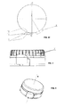
- Fig. 1A shows a cross-section of the cap according to the invention
- Fig. 1B shows an end view of the cap according to the invention
- Fig. 1C shows a top view of the cap according to the invention
- Fig. 2 shows an end view of a plastic body of the cap according to the invention
- Fig. 3 shows a perspective view of the cap according to the invention.
- the safety bottle cap As shown in Fig. 1A , the safety bottle cap according to the invention consists of a metal cover 1 connected to a body 2 made of plastic such as poliethylene or polypropylene.
- the metal cover 1 is made of steel.
- Surface of the metal cover 1 is smooth which allows a decoration to be made thereon, for example in form of a print, whereby the decoration may be made on the top surface of the cover as well as on its peripheral lateral surface.
- the metal cover 1 is connected to the plastic body 2 by means of an adhesive, in particular a hot melt adhesive.
- the plastic body 2 is combined of two parts connected to each other by a plurality of tearable bridges 3.
- the upper part of the body 2 comprises a sealing element 4 to be introduced into the bottle head opening and a sealing lip 5, directed externally at an angle with respect to the cap rotation axis B.
- the sealing lip 5 also compensates axial clearance of the cap on the bottle head.
- the upper part of the body 2 comprises a plurality of inner ribs 6 located peripherally at the inner side of the body 2 contacting the outer peripheral bottle head surface, as well as a plurality of outer ribs 7 ( Fig. 2 ).
- the inner ribs 6 serve for centering the cap on the bottle head and prevent the cap from rotation.
- the inner ribs 7 serve for centering the metal cover 1.
- the upper part of the body 2 On its lower peripheral edge the upper part of the body 2 has a ring-shaped protrusion 8 extending externally in radial direction beyond the outline of the metal cover 1.
- the ring-shaped protrusion 8 serves for masking the edge of the metal cover 1.
- the upper part of the body 2 comprises also a radial protrusion 9 facilitating the cap removal once the control ring is removed.
- the lower part of the cap body 2 is formed as a tearable control ring, which prevents the bottle from being refilled without a visible signs of unauthorised opening of the cap.
- the first opening of the bottle requires complete tearing of the control ring from the upper part of the body 2.
- the control ring comprises a protecting collar 10 directed at an angle to the inside of the ring, the collar 10 engaging into and snapping at an annular groove respectively formed in the bottle head outer surface, thereby preventing the cap from being taken off the bottle head without tearing off the control ring.
- the tearable bridges 3 connecting the upper and lower part of the body 2 can be elongated - respectively - in form of a plurality of inner ribs 6 in the upper part of the body 2 and in form of a plurality of corresponding ribs located peripherally at the inner side of the control ring above the protecting collar 10. Such elongated bridges 3 may also protect the cap from rotating on the bottle head.
- control ring is provided with a tongue 11 facilitating tearing off the control ring from the upper part of the cap body 2.
- the control ring is vertically cut so as to allow it to be torn off by pulling the tongue 11 using considerably little force, thereby eliminating the probability of a complete cap being reused for closing a bottle refilled with non-original content.
- the tongue 11 is protected from protruding too much and the associated risk of uncontrolled tearing off or straining the bridges 3 by the fact that in its lower part the tongue 11 has tearable bridges 12 (preferably two) connecting the tongue 11 with the lower part of the control ring, and by the fact that in its upper part the tongue 11 has a tearable bridge 13 connecting the tongue 11 with the upper part of the cap body 2.
- the bridges 12 also prevent the tongue 11 from being torn or strained during the application of the complete cap onto the bottle head realised by pressing the cap against the bottle head using the force directed vertically downwards.
- the tongue 11 is formed in mould slides being opened perpendicularly to the cap rotation axis B. Further, the formation of incision of the bridges 3 in the cap of the invention is realised by means of slides being opened perpendicularly to the cap rotation axis B.
Description
- The present invention is related to a safety bottle cap adjusted for closing bottle head opening. The cap according to the invention is provided with a control element that is partially destroyed in a visible manner after being opened for the first time. This prevents a bottle containing certain liquid (such as alcoholic beverage) from being refilled with a substitute amount of other liquid of characteristics and quality possibly differing from the original content. At the same time the safety bottle cap still realises its primary function of closing the bottle head opening.
- Many different types of bottle closures are known in the prior art including threaded caps, covers or more complex closures provided with various types of valves (see for example
US 2008/073 382 , upon which the preamble of claim 1 is based. - For example, in
EP 1574450 B1 a safety bottle cap is disclosed comprising a screw cap threadedly engaged with an external sleeve connected to an internal sleeve by means of ribs in such a way that through channels are formed. The cap is provided i.a. with two-part metal enclosure, while the protection against refilling is realised by a combination of protection band and hydraulic interlocking. - Further, in
FR 2908746 A1 - Yet further, in
RU 2307056 C1 - Moreover, in
RU 81480 (U1 - Despite numerous solutions related to closures protecting bottles againts unauthorised refilling, there is a clear constant need for development of new bottle closures characterised by considerably high protection level combined with possibly simple construction, not requring costly setting-up (as in case of multi-element valve systems), allowing for aesthethic appearance, safe use (no sharp edges or protruding elements left after the removal of a control band) and sufficient closure sealing also once the control band is removed. The aim of the invention was to provide a solution meeting these requirements and providing an attractive alternative for the existing solutions.
- The safety bottle cap according to the present invention is defined in the indepedent claim 1. Preferred embodiments thereof are presented in subsequent dependent claims.
- The invention is illustrated with drawings, wherein
Fig. 1A shows a cross-section of the cap according to the invention;Fig. 1B shows an end view of the cap according to the invention;Fig. 1C shows a top view of the cap according to the invention;Fig. 2 shows an end view of a plastic body of the cap according to the invention; andFig. 3 shows a perspective view of the cap according to the invention. - As shown in
Fig. 1A , the safety bottle cap according to the invention consists of a metal cover 1 connected to a body 2 made of plastic such as poliethylene or polypropylene. - Preferably, the metal cover 1 is made of steel. Surface of the metal cover 1 is smooth which allows a decoration to be made thereon, for example in form of a print, whereby the decoration may be made on the top surface of the cover as well as on its peripheral lateral surface.
- Preferably, the metal cover 1 is connected to the plastic body 2 by means of an adhesive, in particular a hot melt adhesive.
- The plastic body 2 is combined of two parts connected to each other by a plurality of
tearable bridges 3. The upper part of the body 2 comprises asealing element 4 to be introduced into the bottle head opening and asealing lip 5, directed externally at an angle with respect to the cap rotation axis B. The sealinglip 5 also compensates axial clearance of the cap on the bottle head. Further, the upper part of the body 2 comprises a plurality of inner ribs 6 located peripherally at the inner side of the body 2 contacting the outer peripheral bottle head surface, as well as a plurality of outer ribs 7 (Fig. 2 ). The inner ribs 6 serve for centering the cap on the bottle head and prevent the cap from rotation. Theinner ribs 7 serve for centering the metal cover 1. On its lower peripheral edge the upper part of the body 2 has a ring-shaped protrusion 8 extending externally in radial direction beyond the outline of the metal cover 1.The ring-shaped protrusion 8 serves for masking the edge of the metal cover 1. As shown inFig. 1C on the lower peripheral edge the upper part of the body 2 comprises also a radial protrusion 9 facilitating the cap removal once the control ring is removed. - The lower part of the cap body 2 is formed as a tearable control ring, which prevents the bottle from being refilled without a visible signs of unauthorised opening of the cap. The first opening of the bottle requires complete tearing of the control ring from the upper part of the body 2. The control ring comprises a protecting
collar 10 directed at an angle to the inside of the ring, thecollar 10 engaging into and snapping at an annular groove respectively formed in the bottle head outer surface, thereby preventing the cap from being taken off the bottle head without tearing off the control ring. - The
tearable bridges 3 connecting the upper and lower part of the body 2 can be elongated - respectively - in form of a plurality of inner ribs 6 in the upper part of the body 2 and in form of a plurality of corresponding ribs located peripherally at the inner side of the control ring above the protectingcollar 10. Suchelongated bridges 3 may also protect the cap from rotating on the bottle head. - As shown in
Fig. 1B the control ring is provided with atongue 11 facilitating tearing off the control ring from the upper part of the cap body 2. During the formation process the control ring is vertically cut so as to allow it to be torn off by pulling thetongue 11 using considerably little force, thereby eliminating the probability of a complete cap being reused for closing a bottle refilled with non-original content. Thetongue 11 is protected from protruding too much and the associated risk of uncontrolled tearing off or straining thebridges 3 by the fact that in its lower part thetongue 11 has tearable bridges 12 (preferably two) connecting thetongue 11 with the lower part of the control ring, and by the fact that in its upper part thetongue 11 has atearable bridge 13 connecting thetongue 11 with the upper part of the cap body 2. Thebridges 12 also prevent thetongue 11 from being torn or strained during the application of the complete cap onto the bottle head realised by pressing the cap against the bottle head using the force directed vertically downwards. - The
tongue 11 is formed in mould slides being opened perpendicularly to the cap rotation axis B. Further, the formation of incision of thebridges 3 in the cap of the invention is realised by means of slides being opened perpendicularly to the cap rotation axis B.
Claims (7)
- A safety bottle cap comprising a plastic body (2) consisting of two parts connected by a plurality of tearable bridges (3), whereby the upper part of the body (2) comprises a sealing element (4) to be introduced into the bottle head opening, a sealing lip (5), a plurality of peripherally located outer ribs (7), and the lower part of the body (2) is in a form of a cut tearable control ring comprising a protecting collar (10) directed at an angle to the inside of the ring, the collar (10) engaging into and snapping at an annular groove respectively formed in the bottle head outer surface, whereby the upper part of the body (2) is provided with a plurality of inner ribs (6) located peripherally at the inner side of the body (2) contacting the outer peripheral bottle head surface characterized in that a metal cover (1) is connected to the plastic body, the control ring further comprises a tongue (11) for tearing off the control ring, provided in its lower part with tearable bridges (12) connecting the tongue to a lower part of the control ring and in that the upper part of the body (2) on its lower peripheral edge has a ring-shaped protrusion (8) extending externally in radial direction beyond the outline of the metal cover (1).
- The safety bottle cap according to claim 1, characterised in that the metal cover (1) is connected to the plastic body (2) by means of an adhesive.
- The safety bottle cap according to claim 1 or 2, characterised in that the upper part of the body (2) on its lower peripheral edge has a radial protrusion (9) facilitating the cap removal once the control ring is removed.
- The safety bottle cap according to any of the claims 1 to 3, characterised in that the sealing lip (5) is directed externally at an angle with respect to the cap rotation axis B.
- The safety bottle cap according to any of the claims 1 to 4, characterised in that in its lower part the tongue (11) is provided with two tearable bridges (12) connecting the tongue (11) to a lower part of the control ring.
- The safety bottle cap according to any of the claims 1 to 5, characterised in that in its upper part the tongue (11) is provided with a tearable bridge (13) connecting the tongue (11) to the upper part of the cap body (2).
- The safety bottle cap according to any of the claims 1 to 6, characterised in that the inner ribs (6) form an enlogated continuation of tearable bridges (3) in the upper part of the body (2), and that a plurality of peripherally located ribs forming an elongated continuation of tearable bridges (3) is provided at the inner side of the control ring above the protecting collar (10).
Priority Applications (11)
| Application Number | Priority Date | Filing Date | Title |
|---|---|---|---|
| SI201030537T SI2444334T1 (en) | 2010-09-28 | 2010-09-28 | Safety bottle cap |
| PT104600408T PT2444334E (en) | 2010-09-28 | 2010-09-28 | Safety bottle cap |
| DK10460040.8T DK2444334T3 (en) | 2010-09-28 | 2010-09-28 | Safety cap BOTTLE |
| PL10460040T PL2444334T3 (en) | 2010-09-28 | 2010-09-28 | Safety bottle cap |
| EP10460040.8A EP2444334B1 (en) | 2010-09-28 | 2010-09-28 | Safety bottle cap |
| ES10460040.8T ES2446276T3 (en) | 2010-09-28 | 2010-09-28 | Safety cap for a bottle |
| RS20140065A RS53193B (en) | 2010-09-28 | 2010-09-28 | Safety bottle cap |
| UAA201014088A UA104722C2 (en) | 2010-09-28 | 2010-11-26 | Safety bottle cap |
| EA201001709A EA020133B1 (en) | 2010-09-28 | 2010-11-26 | Safety bottle cap |
| HRP20140148AT HRP20140148T1 (en) | 2010-09-28 | 2014-02-17 | Safety bottle cap |
| CY20141100117T CY1114999T1 (en) | 2010-09-28 | 2014-02-17 | SAFETY BOTTLE LID |
Applications Claiming Priority (1)
| Application Number | Priority Date | Filing Date | Title |
|---|---|---|---|
| EP10460040.8A EP2444334B1 (en) | 2010-09-28 | 2010-09-28 | Safety bottle cap |
Publications (2)
| Publication Number | Publication Date |
|---|---|
| EP2444334A1 EP2444334A1 (en) | 2012-04-25 |
| EP2444334B1 true EP2444334B1 (en) | 2013-11-27 |
Family
ID=43589543
Family Applications (1)
| Application Number | Title | Priority Date | Filing Date |
|---|---|---|---|
| EP10460040.8A Active EP2444334B1 (en) | 2010-09-28 | 2010-09-28 | Safety bottle cap |
Country Status (11)
| Country | Link |
|---|---|
| EP (1) | EP2444334B1 (en) |
| CY (1) | CY1114999T1 (en) |
| DK (1) | DK2444334T3 (en) |
| EA (1) | EA020133B1 (en) |
| ES (1) | ES2446276T3 (en) |
| HR (1) | HRP20140148T1 (en) |
| PL (1) | PL2444334T3 (en) |
| PT (1) | PT2444334E (en) |
| RS (1) | RS53193B (en) |
| SI (1) | SI2444334T1 (en) |
| UA (1) | UA104722C2 (en) |
Families Citing this family (3)
| Publication number | Priority date | Publication date | Assignee | Title |
|---|---|---|---|---|
| CN104986429B (en) * | 2015-07-08 | 2018-11-09 | 长沙开元仪器股份有限公司 | A kind of mineral samplers collecting tank |
| DE102020129998B3 (en) * | 2020-11-13 | 2021-10-28 | Gaplast Gmbh | Stopper for a container |
| CN113086403B (en) * | 2021-04-30 | 2024-03-22 | 上海宝柏新材料股份有限公司 | Bottle mouth |
Family Cites Families (9)
| Publication number | Priority date | Publication date | Assignee | Title |
|---|---|---|---|---|
| FR1393366A (en) * | 1964-01-22 | 1965-03-26 | Improvements to caps for containers | |
| US3797688A (en) * | 1972-06-14 | 1974-03-19 | Federal Tool & Plastics | Safety cap unit |
| RU2225337C1 (en) | 2003-01-17 | 2004-03-10 | Иностранное унитарное производственное предприятие "Белкэпс" | Bottle safety cap |
| FR2793216B1 (en) * | 1999-04-20 | 2001-06-08 | Pechiney Emballage Alimentaire | COMPOSITE CAPPING CAPSULE |
| US20050077263A1 (en) * | 2003-10-10 | 2005-04-14 | Garcia Omar Alcides | Bottle stopper |
| GB2451775A (en) * | 2004-12-23 | 2009-02-11 | Abacus | A dispensing closure assembly |
| RU2307056C1 (en) | 2006-09-12 | 2007-09-27 | ООО "Завод упаковочных изделий "ТОКК" | Bottle cap |
| FR2908746B1 (en) | 2006-11-20 | 2009-01-09 | Tetra Laval Holdings & Finance | CAP FOR A COLLAR OF A CONTAINER AND METHOD OF MANUFACTURING SUCH A PLUG |
| RU81480U1 (en) | 2008-07-11 | 2009-03-20 | Общество с ограниченной ответственностью "Завод упаковочных изделий ТОКК" | COVER-CORK |
-
2010
- 2010-09-28 SI SI201030537T patent/SI2444334T1/en unknown
- 2010-09-28 PL PL10460040T patent/PL2444334T3/en unknown
- 2010-09-28 PT PT104600408T patent/PT2444334E/en unknown
- 2010-09-28 RS RS20140065A patent/RS53193B/en unknown
- 2010-09-28 EP EP10460040.8A patent/EP2444334B1/en active Active
- 2010-09-28 DK DK10460040.8T patent/DK2444334T3/en active
- 2010-09-28 ES ES10460040.8T patent/ES2446276T3/en active Active
- 2010-11-26 EA EA201001709A patent/EA020133B1/en unknown
- 2010-11-26 UA UAA201014088A patent/UA104722C2/en unknown
-
2014
- 2014-02-17 CY CY20141100117T patent/CY1114999T1/en unknown
- 2014-02-17 HR HRP20140148AT patent/HRP20140148T1/en unknown
Also Published As
| Publication number | Publication date |
|---|---|
| EA020133B1 (en) | 2014-08-29 |
| PL2444334T3 (en) | 2014-05-30 |
| SI2444334T1 (en) | 2014-03-31 |
| RS53193B (en) | 2014-06-30 |
| DK2444334T3 (en) | 2014-02-24 |
| EP2444334A1 (en) | 2012-04-25 |
| ES2446276T3 (en) | 2014-03-06 |
| UA104722C2 (en) | 2014-03-11 |
| EA201001709A1 (en) | 2012-02-28 |
| PT2444334E (en) | 2014-02-20 |
| CY1114999T1 (en) | 2016-12-14 |
| HRP20140148T1 (en) | 2014-04-11 |
Similar Documents
| Publication | Publication Date | Title |
|---|---|---|
| EP3784584B1 (en) | Closure | |
| EP3411300B1 (en) | Improvements in or relating to tamper-evident closures | |
| EP1964787B1 (en) | Tamper evident closure for containers provided with a threaded neck | |
| US7121419B2 (en) | Closure | |
| EP2444334B1 (en) | Safety bottle cap | |
| US6981600B1 (en) | Tamper evident closure for bottles of quality liquor | |
| CN102076573B (en) | A tamper-evident closure | |
| EP2484600A1 (en) | Closure assembly for a container | |
| EP2380820B1 (en) | A closure assembly | |
| CN109843735B (en) | Double-layer tamper-evident closure for a container neck, system comprising a container and said closure and method for manufacturing said closure | |
| CN109890708B (en) | Double-layer tamper-evident closure for a container neck, system comprising a container and said closure and method for manufacturing said closure | |
| PL72002Y1 (en) | Screw cap stopper for a bottle | |
| JP4846526B2 (en) | Plastic container | |
| EP2280880B1 (en) | A decorative, tamperproof, closure | |
| JP5603179B2 (en) | Combination of container and lid and packaging method using such combination | |
| WO2001064538A1 (en) | A security closure for bottles and the like | |
| JP4906560B2 (en) | Plastic container lid | |
| ITPD20120263A1 (en) | PLUG WITH MUSHROOM HEAD AND BREATHING EVIDENTATOR | |
| RU194088U1 (en) | OPENING INDICATOR FOR CUTTER DEVICE | |
| TWI807437B (en) | Cut link cover | |
| WO2007033686A1 (en) | Decapsulation-displaying closing cap | |
| RU126686U1 (en) | BOTTLE COVER | |
| UA147800U (en) | MEANS OF INDICATION OF CLOSING DEVICE DISCLOSURE | |
| JP4628111B2 (en) | Cap for liquid container | |
| CN115892721A (en) | Cutting connection cover |
Legal Events
| Date | Code | Title | Description |
|---|---|---|---|
| AK | Designated contracting states |
Kind code of ref document: A1 Designated state(s): AL AT BE BG CH CY CZ DE DK EE ES FI FR GB GR HR HU IE IS IT LI LT LU LV MC MK MT NL NO PL PT RO SE SI SK SM TR |
|
| AX | Request for extension of the european patent |
Extension state: BA ME RS |
|
| PUAI | Public reference made under article 153(3) epc to a published international application that has entered the european phase |
Free format text: ORIGINAL CODE: 0009012 |
|
| 17P | Request for examination filed |
Effective date: 20120523 |
|
| GRAP | Despatch of communication of intention to grant a patent |
Free format text: ORIGINAL CODE: EPIDOSNIGR1 |
|
| RIC1 | Information provided on ipc code assigned before grant |
Ipc: B65D 41/46 20060101AFI20130531BHEP Ipc: B65D 41/62 20060101ALI20130531BHEP |
|
| INTG | Intention to grant announced |
Effective date: 20130619 |
|
| GRAS | Grant fee paid |
Free format text: ORIGINAL CODE: EPIDOSNIGR3 |
|
| GRAA | (expected) grant |
Free format text: ORIGINAL CODE: 0009210 |
|
| AK | Designated contracting states |
Kind code of ref document: B1 Designated state(s): AL AT BE BG CH CY CZ DE DK EE ES FI FR GB GR HR HU IE IS IT LI LT LU LV MC MK MT NL NO PL PT RO SE SI SK SM TR |
|
| AX | Request for extension of the european patent |
Extension state: BA ME RS |
|
| REG | Reference to a national code |
Ref country code: GB Ref legal event code: FG4D |
|
| REG | Reference to a national code |
Ref country code: CH Ref legal event code: EP |
|
| REG | Reference to a national code |
Ref country code: AT Ref legal event code: REF Ref document number: 642591 Country of ref document: AT Kind code of ref document: T Effective date: 20131215 |
|
| REG | Reference to a national code |
Ref country code: IE Ref legal event code: FG4D |
|
| REG | Reference to a national code |
Ref country code: DE Ref legal event code: R096 Ref document number: 602010012042 Country of ref document: DE Effective date: 20140123 |
|
| REG | Reference to a national code |
Ref country code: RO Ref legal event code: EPE |
|
| REG | Reference to a national code |
Ref country code: HR Ref legal event code: TUEP Ref document number: P20140148 Country of ref document: HR |
|
| REG | Reference to a national code |
Ref country code: PT Ref legal event code: SC4A Free format text: AVAILABILITY OF NATIONAL TRANSLATION Effective date: 20140211 |
|
| REG | Reference to a national code |
Ref country code: DK Ref legal event code: T3 Effective date: 20140217 |
|
| REG | Reference to a national code |
Ref country code: NL Ref legal event code: T3 |
|
| REG | Reference to a national code |
Ref country code: ES Ref legal event code: FG2A Ref document number: 2446276 Country of ref document: ES Kind code of ref document: T3 Effective date: 20140306 |
|
| REG | Reference to a national code |
Ref country code: SE Ref legal event code: TRGR |
|
| REG | Reference to a national code |
Ref country code: NO Ref legal event code: T2 Effective date: 20131127 |
|
| REG | Reference to a national code |
Ref country code: HR Ref legal event code: T1PR Ref document number: P20140148 Country of ref document: HR |
|
| REG | Reference to a national code |
Ref country code: GR Ref legal event code: EP Ref document number: 20140400317 Country of ref document: GR Effective date: 20140317 |
|
| REG | Reference to a national code |
Ref country code: PL Ref legal event code: T3 |
|
| REG | Reference to a national code |
Ref country code: EE Ref legal event code: FG4A Ref document number: E009097 Country of ref document: EE Effective date: 20140217 |
|
| REG | Reference to a national code |
Ref country code: SK Ref legal event code: T3 Ref document number: E 16050 Country of ref document: SK |
|
| REG | Reference to a national code |
Ref country code: DE Ref legal event code: R097 Ref document number: 602010012042 Country of ref document: DE Ref country code: HU Ref legal event code: AG4A Ref document number: E020247 Country of ref document: HU |
|
| PLBE | No opposition filed within time limit |
Free format text: ORIGINAL CODE: 0009261 |
|
| STAA | Information on the status of an ep patent application or granted ep patent |
Free format text: STATUS: NO OPPOSITION FILED WITHIN TIME LIMIT |
|
| 26N | No opposition filed |
Effective date: 20140828 |
|
| REG | Reference to a national code |
Ref country code: DE Ref legal event code: R097 Ref document number: 602010012042 Country of ref document: DE Effective date: 20140828 |
|
| PG25 | Lapsed in a contracting state [announced via postgrant information from national office to epo] |
Ref country code: SM Free format text: LAPSE BECAUSE OF FAILURE TO SUBMIT A TRANSLATION OF THE DESCRIPTION OR TO PAY THE FEE WITHIN THE PRESCRIBED TIME-LIMIT Effective date: 20131127 |
|
| REG | Reference to a national code |
Ref country code: FR Ref legal event code: PLFP Year of fee payment: 7 |
|
| REG | Reference to a national code |
Ref country code: HR Ref legal event code: ODRP Ref document number: P20140148 Country of ref document: HR Payment date: 20170623 Year of fee payment: 8 |
|
| PGFP | Annual fee paid to national office [announced via postgrant information from national office to epo] |
Ref country code: CH Payment date: 20170426 Year of fee payment: 8 Ref country code: IS Payment date: 20170630 Year of fee payment: 8 Ref country code: NO Payment date: 20170622 Year of fee payment: 8 |
|
| PGFP | Annual fee paid to national office [announced via postgrant information from national office to epo] |
Ref country code: PT Payment date: 20170622 Year of fee payment: 8 Ref country code: LU Payment date: 20170710 Year of fee payment: 8 |
|
| PGFP | Annual fee paid to national office [announced via postgrant information from national office to epo] |
Ref country code: TR Payment date: 20170621 Year of fee payment: 8 |
|
| REG | Reference to a national code |
Ref country code: FR Ref legal event code: PLFP Year of fee payment: 8 |
|
| PGFP | Annual fee paid to national office [announced via postgrant information from national office to epo] |
Ref country code: FI Payment date: 20170711 Year of fee payment: 8 Ref country code: CH Payment date: 20170809 Year of fee payment: 8 Ref country code: MC Payment date: 20170914 Year of fee payment: 8 Ref country code: CY Payment date: 20170628 Year of fee payment: 8 |
|
| PGFP | Annual fee paid to national office [announced via postgrant information from national office to epo] |
Ref country code: SE Payment date: 20170711 Year of fee payment: 8 Ref country code: IE Payment date: 20170831 Year of fee payment: 8 Ref country code: SI Payment date: 20170621 Year of fee payment: 8 Ref country code: HU Payment date: 20170628 Year of fee payment: 8 |
|
| PGFP | Annual fee paid to national office [announced via postgrant information from national office to epo] |
Ref country code: AL Payment date: 20170630 Year of fee payment: 8 |
|
| PGFP | Annual fee paid to national office [announced via postgrant information from national office to epo] |
Ref country code: MK Payment date: 20170621 Year of fee payment: 8 |
|
| REG | Reference to a national code |
Ref country code: FR Ref legal event code: PLFP Year of fee payment: 9 |
|
| PGFP | Annual fee paid to national office [announced via postgrant information from national office to epo] |
Ref country code: LT Payment date: 20180910 Year of fee payment: 9 Ref country code: DE Payment date: 20180906 Year of fee payment: 9 Ref country code: RO Payment date: 20180903 Year of fee payment: 9 Ref country code: IT Payment date: 20180910 Year of fee payment: 9 Ref country code: EE Payment date: 20180903 Year of fee payment: 9 |
|
| PGFP | Annual fee paid to national office [announced via postgrant information from national office to epo] |
Ref country code: AT Payment date: 20180925 Year of fee payment: 9 Ref country code: LV Payment date: 20180906 Year of fee payment: 9 Ref country code: DK Payment date: 20180917 Year of fee payment: 9 Ref country code: BG Payment date: 20180903 Year of fee payment: 9 Ref country code: GB Payment date: 20180903 Year of fee payment: 9 Ref country code: NL Payment date: 20180911 Year of fee payment: 9 Ref country code: GR Payment date: 20180911 Year of fee payment: 9 Ref country code: CZ Payment date: 20180903 Year of fee payment: 9 |
|
| PGFP | Annual fee paid to national office [announced via postgrant information from national office to epo] |
Ref country code: MT Payment date: 20180907 Year of fee payment: 9 |
|
| PGFP | Annual fee paid to national office [announced via postgrant information from national office to epo] |
Ref country code: FR Payment date: 20181001 Year of fee payment: 9 Ref country code: ES Payment date: 20181001 Year of fee payment: 9 |
|
| REG | Reference to a national code |
Ref country code: HR Ref legal event code: PBON Ref document number: P20140148 Country of ref document: HR Effective date: 20180928 |
|
| REG | Reference to a national code |
Ref country code: NO Ref legal event code: MMEP |
|
| PG25 | Lapsed in a contracting state [announced via postgrant information from national office to epo] |
Ref country code: FI Free format text: LAPSE BECAUSE OF NON-PAYMENT OF DUE FEES Effective date: 20180928 Ref country code: MC Free format text: LAPSE BECAUSE OF NON-PAYMENT OF DUE FEES Effective date: 20181001 Ref country code: IS Free format text: LAPSE BECAUSE OF FAILURE TO SUBMIT A TRANSLATION OF THE DESCRIPTION OR TO PAY THE FEE WITHIN THE PRESCRIBED TIME-LIMIT Effective date: 20190331 Ref country code: CY Free format text: LAPSE BECAUSE OF NON-PAYMENT OF DUE FEES Effective date: 20180928 |
|
| REG | Reference to a national code |
Ref country code: SE Ref legal event code: EUG Ref country code: CH Ref legal event code: PL |
|
| PG25 | Lapsed in a contracting state [announced via postgrant information from national office to epo] |
Ref country code: PT Free format text: LAPSE BECAUSE OF NON-PAYMENT OF DUE FEES Effective date: 20190328 Ref country code: SE Free format text: LAPSE BECAUSE OF NON-PAYMENT OF DUE FEES Effective date: 20180929 |
|
| REG | Reference to a national code |
Ref country code: SK Ref legal event code: MM4A Ref document number: E 16050 Country of ref document: SK Effective date: 20180928 |
|
| REG | Reference to a national code |
Ref country code: IE Ref legal event code: MM4A |
|
| PG25 | Lapsed in a contracting state [announced via postgrant information from national office to epo] |
Ref country code: LU Free format text: LAPSE BECAUSE OF NON-PAYMENT OF DUE FEES Effective date: 20180928 |
|
| REG | Reference to a national code |
Ref country code: SI Ref legal event code: KO00 Effective date: 20190507 |
|
| PG25 | Lapsed in a contracting state [announced via postgrant information from national office to epo] |
Ref country code: NO Free format text: LAPSE BECAUSE OF NON-PAYMENT OF DUE FEES Effective date: 20180930 Ref country code: IE Free format text: LAPSE BECAUSE OF NON-PAYMENT OF DUE FEES Effective date: 20180928 |
|
| PG25 | Lapsed in a contracting state [announced via postgrant information from national office to epo] |
Ref country code: SK Free format text: LAPSE BECAUSE OF NON-PAYMENT OF DUE FEES Effective date: 20180928 Ref country code: CH Free format text: LAPSE BECAUSE OF NON-PAYMENT OF DUE FEES Effective date: 20180930 Ref country code: HR Free format text: LAPSE BECAUSE OF NON-PAYMENT OF DUE FEES Effective date: 20180928 Ref country code: LI Free format text: LAPSE BECAUSE OF NON-PAYMENT OF DUE FEES Effective date: 20180930 Ref country code: SI Free format text: LAPSE BECAUSE OF NON-PAYMENT OF DUE FEES Effective date: 20180929 Ref country code: HU Free format text: LAPSE BECAUSE OF NON-PAYMENT OF DUE FEES Effective date: 20180929 |
|
| REG | Reference to a national code |
Ref country code: DE Ref legal event code: R119 Ref document number: 602010012042 Country of ref document: DE |
|
| REG | Reference to a national code |
Ref country code: EE Ref legal event code: MM4A Ref document number: E009097 Country of ref document: EE Effective date: 20190930 |
|
| REG | Reference to a national code |
Ref country code: DK Ref legal event code: EBP Effective date: 20190930 |
|
| PG25 | Lapsed in a contracting state [announced via postgrant information from national office to epo] |
Ref country code: RO Free format text: LAPSE BECAUSE OF NON-PAYMENT OF DUE FEES Effective date: 20190928 Ref country code: LV Free format text: LAPSE BECAUSE OF NON-PAYMENT OF DUE FEES Effective date: 20190928 |
|
| REG | Reference to a national code |
Ref country code: NL Ref legal event code: MM Effective date: 20191001 |
|
| PG25 | Lapsed in a contracting state [announced via postgrant information from national office to epo] |
Ref country code: CZ Free format text: LAPSE BECAUSE OF NON-PAYMENT OF DUE FEES Effective date: 20190928 |
|
| REG | Reference to a national code |
Ref country code: LT Ref legal event code: MM4D Effective date: 20190928 |
|
| PG25 | Lapsed in a contracting state [announced via postgrant information from national office to epo] |
Ref country code: NL Free format text: LAPSE BECAUSE OF NON-PAYMENT OF DUE FEES Effective date: 20191001 Ref country code: LT Free format text: LAPSE BECAUSE OF NON-PAYMENT OF DUE FEES Effective date: 20190928 Ref country code: GR Free format text: LAPSE BECAUSE OF NON-PAYMENT OF DUE FEES Effective date: 20200416 Ref country code: EE Free format text: LAPSE BECAUSE OF NON-PAYMENT OF DUE FEES Effective date: 20190930 Ref country code: DE Free format text: LAPSE BECAUSE OF NON-PAYMENT OF DUE FEES Effective date: 20200401 |
|
| REG | Reference to a national code |
Ref country code: BE Ref legal event code: MM Effective date: 20190930 |
|
| REG | Reference to a national code |
Ref country code: AT Ref legal event code: MM01 Ref document number: 642591 Country of ref document: AT Kind code of ref document: T Effective date: 20190928 |
|
| PG25 | Lapsed in a contracting state [announced via postgrant information from national office to epo] |
Ref country code: IT Free format text: LAPSE BECAUSE OF NON-PAYMENT OF DUE FEES Effective date: 20190928 Ref country code: BG Free format text: LAPSE BECAUSE OF NON-PAYMENT OF DUE FEES Effective date: 20200531 Ref country code: BE Free format text: LAPSE BECAUSE OF NON-PAYMENT OF DUE FEES Effective date: 20190930 |
|
| GBPC | Gb: european patent ceased through non-payment of renewal fee |
Effective date: 20190928 |
|
| PG25 | Lapsed in a contracting state [announced via postgrant information from national office to epo] |
Ref country code: FR Free format text: LAPSE BECAUSE OF NON-PAYMENT OF DUE FEES Effective date: 20190930 Ref country code: GB Free format text: LAPSE BECAUSE OF NON-PAYMENT OF DUE FEES Effective date: 20190928 Ref country code: DK Free format text: LAPSE BECAUSE OF NON-PAYMENT OF DUE FEES Effective date: 20190930 |
|
| PG25 | Lapsed in a contracting state [announced via postgrant information from national office to epo] |
Ref country code: AT Free format text: LAPSE BECAUSE OF NON-PAYMENT OF DUE FEES Effective date: 20190928 |
|
| PG25 | Lapsed in a contracting state [announced via postgrant information from national office to epo] |
Ref country code: AL Free format text: LAPSE BECAUSE OF NON-PAYMENT OF DUE FEES Effective date: 20180928 |
|
| REG | Reference to a national code |
Ref country code: ES Ref legal event code: FD2A Effective date: 20210202 |
|
| PG25 | Lapsed in a contracting state [announced via postgrant information from national office to epo] |
Ref country code: ES Free format text: LAPSE BECAUSE OF NON-PAYMENT OF DUE FEES Effective date: 20190929 |
|
| PG25 | Lapsed in a contracting state [announced via postgrant information from national office to epo] |
Ref country code: MT Free format text: LAPSE BECAUSE OF FAILURE TO SUBMIT A TRANSLATION OF THE DESCRIPTION OR TO PAY THE FEE WITHIN THE PRESCRIBED TIME-LIMIT Effective date: 20190928 |
|
| PG25 | Lapsed in a contracting state [announced via postgrant information from national office to epo] |
Ref country code: TR Free format text: LAPSE BECAUSE OF NON-PAYMENT OF DUE FEES Effective date: 20180928 |
|
| PGFP | Annual fee paid to national office [announced via postgrant information from national office to epo] |
Ref country code: PL Payment date: 20230811 Year of fee payment: 14 |