EP2444306A1 - Airbag device for straddle type vehicles - Google Patents
Airbag device for straddle type vehicles Download PDFInfo
- Publication number
- EP2444306A1 EP2444306A1 EP10789560A EP10789560A EP2444306A1 EP 2444306 A1 EP2444306 A1 EP 2444306A1 EP 10789560 A EP10789560 A EP 10789560A EP 10789560 A EP10789560 A EP 10789560A EP 2444306 A1 EP2444306 A1 EP 2444306A1
- Authority
- EP
- European Patent Office
- Prior art keywords
- lid
- air bag
- retaining box
- strip
- restricting means
- Prior art date
- Legal status (The legal status is an assumption and is not a legal conclusion. Google has not performed a legal analysis and makes no representation as to the accuracy of the status listed.)
- Granted
Links
Images







Classifications
-
- B—PERFORMING OPERATIONS; TRANSPORTING
- B60—VEHICLES IN GENERAL
- B60R—VEHICLES, VEHICLE FITTINGS, OR VEHICLE PARTS, NOT OTHERWISE PROVIDED FOR
- B60R21/00—Arrangements or fittings on vehicles for protecting or preventing injuries to occupants or pedestrians in case of accidents or other traffic risks
- B60R21/02—Occupant safety arrangements or fittings, e.g. crash pads
- B60R21/16—Inflatable occupant restraints or confinements designed to inflate upon impact or impending impact, e.g. air bags
- B60R21/20—Arrangements for storing inflatable members in their non-use or deflated condition; Arrangement or mounting of air bag modules or components
- B60R21/215—Arrangements for storing inflatable members in their non-use or deflated condition; Arrangement or mounting of air bag modules or components characterised by the covers for the inflatable member
-
- B—PERFORMING OPERATIONS; TRANSPORTING
- B60—VEHICLES IN GENERAL
- B60R—VEHICLES, VEHICLE FITTINGS, OR VEHICLE PARTS, NOT OTHERWISE PROVIDED FOR
- B60R21/00—Arrangements or fittings on vehicles for protecting or preventing injuries to occupants or pedestrians in case of accidents or other traffic risks
- B60R21/02—Occupant safety arrangements or fittings, e.g. crash pads
- B60R21/16—Inflatable occupant restraints or confinements designed to inflate upon impact or impending impact, e.g. air bags
- B60R21/20—Arrangements for storing inflatable members in their non-use or deflated condition; Arrangement or mounting of air bag modules or components
- B60R21/215—Arrangements for storing inflatable members in their non-use or deflated condition; Arrangement or mounting of air bag modules or components characterised by the covers for the inflatable member
- B60R21/216—Arrangements for storing inflatable members in their non-use or deflated condition; Arrangement or mounting of air bag modules or components characterised by the covers for the inflatable member comprising tether means for limitation of cover motion during deployment
-
- B—PERFORMING OPERATIONS; TRANSPORTING
- B62—LAND VEHICLES FOR TRAVELLING OTHERWISE THAN ON RAILS
- B62J—CYCLE SADDLES OR SEATS; AUXILIARY DEVICES OR ACCESSORIES SPECIALLY ADAPTED TO CYCLES AND NOT OTHERWISE PROVIDED FOR, e.g. ARTICLE CARRIERS OR CYCLE PROTECTORS
- B62J27/00—Safety equipment
- B62J27/20—Airbags specially adapted for motorcycles or the like
-
- B—PERFORMING OPERATIONS; TRANSPORTING
- B60—VEHICLES IN GENERAL
- B60R—VEHICLES, VEHICLE FITTINGS, OR VEHICLE PARTS, NOT OTHERWISE PROVIDED FOR
- B60R21/00—Arrangements or fittings on vehicles for protecting or preventing injuries to occupants or pedestrians in case of accidents or other traffic risks
- B60R2021/0065—Type of vehicles
- B60R2021/0088—Cycles, e.g. motorcycles
-
- B—PERFORMING OPERATIONS; TRANSPORTING
- B60—VEHICLES IN GENERAL
- B60R—VEHICLES, VEHICLE FITTINGS, OR VEHICLE PARTS, NOT OTHERWISE PROVIDED FOR
- B60R21/00—Arrangements or fittings on vehicles for protecting or preventing injuries to occupants or pedestrians in case of accidents or other traffic risks
- B60R21/02—Occupant safety arrangements or fittings, e.g. crash pads
- B60R21/16—Inflatable occupant restraints or confinements designed to inflate upon impact or impending impact, e.g. air bags
- B60R2021/161—Inflatable occupant restraints or confinements designed to inflate upon impact or impending impact, e.g. air bags characterised by additional means for controlling deployment trajectory
-
- B—PERFORMING OPERATIONS; TRANSPORTING
- B60—VEHICLES IN GENERAL
- B60R—VEHICLES, VEHICLE FITTINGS, OR VEHICLE PARTS, NOT OTHERWISE PROVIDED FOR
- B60R21/00—Arrangements or fittings on vehicles for protecting or preventing injuries to occupants or pedestrians in case of accidents or other traffic risks
- B60R21/02—Occupant safety arrangements or fittings, e.g. crash pads
- B60R21/16—Inflatable occupant restraints or confinements designed to inflate upon impact or impending impact, e.g. air bags
- B60R21/20—Arrangements for storing inflatable members in their non-use or deflated condition; Arrangement or mounting of air bag modules or components
- B60R21/215—Arrangements for storing inflatable members in their non-use or deflated condition; Arrangement or mounting of air bag modules or components characterised by the covers for the inflatable member
- B60R21/216—Arrangements for storing inflatable members in their non-use or deflated condition; Arrangement or mounting of air bag modules or components characterised by the covers for the inflatable member comprising tether means for limitation of cover motion during deployment
- B60R2021/2163—Arrangements for storing inflatable members in their non-use or deflated condition; Arrangement or mounting of air bag modules or components characterised by the covers for the inflatable member comprising tether means for limitation of cover motion during deployment with energy absorbing or elastic means
-
- B—PERFORMING OPERATIONS; TRANSPORTING
- B60—VEHICLES IN GENERAL
- B60R—VEHICLES, VEHICLE FITTINGS, OR VEHICLE PARTS, NOT OTHERWISE PROVIDED FOR
- B60R21/00—Arrangements or fittings on vehicles for protecting or preventing injuries to occupants or pedestrians in case of accidents or other traffic risks
- B60R21/02—Occupant safety arrangements or fittings, e.g. crash pads
- B60R21/16—Inflatable occupant restraints or confinements designed to inflate upon impact or impending impact, e.g. air bags
- B60R21/26—Inflatable occupant restraints or confinements designed to inflate upon impact or impending impact, e.g. air bags characterised by the inflation fluid source or means to control inflation fluid flow
- B60R21/263—Inflatable occupant restraints or confinements designed to inflate upon impact or impending impact, e.g. air bags characterised by the inflation fluid source or means to control inflation fluid flow using a variable source, e.g. plural stage or controlled output
Definitions
- the present invention relates to improvement in an air bag apparatus for a saddle-ride type vehicle.
- Saddle-ride type vehicles include air bag apparatuses disposed forward of rider's seats to be inflated or deployed when the vehicles are subject to impact, as disclosed in Patent Literatures 1 and 2 below.
- An air bag apparatus disclosed in Patent Literature 1 includes an air bag stored in a bag housing disposed forward of a fuel tank located forward of a seat mounted on a frame of a motorcycle.
- a restrainer extends rearward from a middle part of a rear side of the air bag for restraining the air bag as the air bag is deployed.
- the restrainer has one end coupled to the frame under the seat.
- a lid disposed on a top of the bag housing pivots upward to an opened portion on a hinge located at a front side of the bag housing.
- the air bag is further deployed out of the bag housing, when the restrainer stretches to hold the deployed air bag in a desired position.
- the restrainer which holds the air bag in the desired position, is essential for the air bag apparatus of Patent Literature 1.
- the restrainer extends out of the bag housing to the frame of the motorcycle, which provides aesthetically adverse effect on the air bag apparatus.
- effort has been made to develop an air bag apparatus disclosed in Patent Literature 2 below.
- the air bag apparatus disclosed in Patent Literature includes an air bag stored in a bag housing disposed directly forward of a seat mounted on a frame of a motorcycle.
- a fuel tank is disposed forward of the bag housing.
- Patent Literature As the air bag begins to be deployed, a lid disposed at a top of the bag housing pivots upward to an opened position. Finally, the air bag is deployed vertically upward.
- the air bag apparatus of Patent Literature is featured by not only elimination of the restrainer disclosed in Patent Literature 1 but also the disposition of the bag housing directly forward of the seat to shorten a distance between the bag housing and a rider.
- an air bag be deployed between a rider and a vehicle front side including a handle etc. in such a manner as to support the rider after the deployed air bag comes into contact with the vehicle front side.
- the air bag of the air bag apparatus which is deployed vertically upward, supports the rider before making contact with the vehicle front side. This implies that a direction of deployment of the air bag is important in supporting the rider. There is need for improvement in the air bag apparatus to control a direction of deployment of the air bag.
- An object of the present invention to provide a saddle-ride air bag apparatus configured to allow an air bag to be deployment in a desired direction.
- An air bag apparatus for a saddle-ride type vehicle comprising: a retaining box disposed on a vehicle body of the vehicle and located directly forward of a rider's seat; an air bag stored in the retaining box and configured to be deployed forward of a rider; a lid for closing an opening portion of the retaining box, the lid having a hinge portion formed on a rear side thereof for allowing the lid to pivot on the hinge portion during deployment of the air bag; and lid restricting means disposed between the lid and the retaining box for restricting an angle through which the lid pivots on the hinge portion away from the opening portion of the retaining box.
- the apparatus further comprises left and right lid stays integral with the lid, the lid restricting means being provided at each of the lid stays.
- the lid restricting means comprises a link mechanism.
- the lid restricting means comprises a strip.
- the lid stays are insert-molded into the lid.
- the lid restricting means restricts the angle to less than 90 degrees relative to a road surface with the air bag apparatus carried on the vehicle.
- the strip includes a fragile portion formed longitudinally thereof, and the apparatus further comprises a fastener holding one end of the fragile portion to the retaining box.
- the lid is pivotable away from the opening portion through a predetermined angle while allowing the fastener to break the fragile portion.
- the strip extends inside the lid and between left and right sides of the lid, the apparatus further comprising a guide member disposed inside the lid and retaining the strip, the lid being pivotable away from the opening portion through a predetermined angle while allowing the strip to travel between the lid and the guide member.
- the air bag apparatus includes lid restricting means disposed between the lid and the retaining box for restricting the angle through which the lid pivots away from the retaining box.
- the lid restricting means restricts a direction of the air bag deployment, which causes the pivotal movement of the lid away from the retaining box.
- the lid restricting means allows for the deployment of the air bag in a desired direction.
- the left and right lid stays provided at the lid allow for even dispersion of impact throughout the lid during the pivotal movement of the lid.
- the lid, which is provided with these lid stays, is easy to design.
- the lid restricting means comprises the link mechanism having links configured to be aligned with each other during the pivotal movement of the lid.
- the aligned links restrains the air bag from expanding outward of the links, guiding the air bag in such a manner as to be deployed toward a desired region.
- the lid restricting means comprises the strip. Use of the strip helps reduce the components of the air bag apparatus unlike use of a multi-piece mechanism. The reduction in the number of the components of the apparatus reduces cost of the apparatus.
- the lid and the lid stay are integrated together by insert molding without use of any fasteners. This leads to reduction in the number of components of the air bag apparatus.
- the angle through which the lid pivots away from the retaining box is set to be less than 90 degrees for allowing the air bag to be deployed spreading out from a front side of the retaining box to a region above the retaining box even if a rider is forced to shift forward.
- the lid pivots away from the retaining box through a predetermined angle allowing the fastener on the retaining box to break the strip along the fragile portion of the strip.
- the breaking of the strip along the fragile portion helps slow down the pivotal movement of the lid during the deployment of the air bag.
- the strip which extends inside the lid between the left and right sides of the lid, is retained by the guide members.
- the guide members restrict movement of the strip to allow the lid to pivot away from the retaining box through a predetermined angle.
- the restricted movement of the strip slows down the pivotal movement of the lid.
- a motorcycle 10 which is a saddle-ride type vehicle, includes a headpipe 11.
- a vehicle body frame 12 extends rearward.
- the vehicle body frame 12 includes the headpipe 11 forming a front part of a vehicle body 14, a main frame 15 extending rearward from the headpipe 11, and a pivot plate 17 attached to a rear end of the main frame 15 and carrying a pivot shaft 16.
- the vehicle body frame 12 further includes a seat rail 18 extending upward and rearward from a top of the pivot plate 17, and a middle frame 19 interconnecting a rear end of the seat rail 18 and a middle of the pivot plate 17 and supporting the seat rail 18.
- the seat rail 18 forms a rear part of the vehicle body frame 12. Attached to a bottom of the pivot plate 17 is a footrest 20 for a rider's foot to rest on.
- a sub-rail 21 extends rearward from an upper end of the middle frame 19.
- the sub-rail 21 has its rear part connected to the middle frame 19 through a seat stay 22.
- An auxiliary stay 23 extends downward and rearward from a rear part of the seat stay 22, and then runs horizontally.
- Mounted on the sub-rail 21 is a trunk 27 for storing articles.
- the trunk 27 has its front wall 27a to which is attached a backrest 28 for supporting a back of a rider.
- An engine 32 is fixed below the main frame 15 with fasteners 31a to 31c.
- the engine 32 is, for example, a flat-six, water-cooled engine.
- a rear swing arm 34 pivotable vertically on the pivot shaft 16.
- the rear swing arm 34 has its rear end to which is attached a rear axle 35.
- a rear wheel 36 is rotationally attached to the rear axle 35.
- Mounted to the rear wheel 36 is a driven sprocket 41.
- the engine 32 has a drive shaft 37 to which is attached a drive sprocket 38.
- the rear wheel 36 is driven by a chain 42 extending around the sprockets 38, 41.
- the rear swing arm 34 carries a link mechanism 47 to which is attached a lower end of a rear cushion unit 48.
- the rear cushion unit 48 has its upper end attached to a bracket 49 disposed near the main frame 15.
- the front folk 52 carries a front axle 53.
- a front wheel 54 is rotationally attached to the front axle 53.
- the front folk 53 has its upper end to which is mounted a steering handle 55 supported by the headpipe 11.
- a main cowl 56 having an opening 57 formed at a side thereof.
- a radiator unit 58 for cooling the engine 32 is positioned facing the opening 57.
- a front disc plate 62 is integral with the front wheel 54.
- the front folk 52 carries a front disc brake unit 61 for sandwiching the front disc plate 62.
- a front cowl 63 covering a front part of the motorcycle 10.
- a front shield 64 extends from a top of the front cowl 63.
- a main stand bracket 68 Provided at a lower end of the pivot plate 17 is a main stand bracket 68.
- a main stand 69 is attached to the main stand bracket 68.
- a battery 67 is disposed below a rider's seat 71 for a rider to sit on.
- a meter 70 is disposed rearward of the front shield 64.
- the seat 71 is disposed on the seat rail 18.
- the seat 71 includes a front seat portion 72 and a rear seat portion 73 disposed rearward of and contiguous with the front seat portion 72.
- An air bag apparatus 86 includes an air bag module 82 and an air bag control unit 87 for controlling deployment of an air bag 150 ( Fig. 4 ) stored in the air bag module 82.
- the air bag module 82 is disposed proximate the seat 71.
- the air bag module 82 includes a retaining box 121, which is a case.
- the retaining box 121 is disposed directly forward of the seat 71.
- first and second sensors 77, 78 Disposed at top and bottom portions of the front folk 52 are first and second sensors 77, 78 for detecting impact on the vehicle body 14.
- a first cable 79 extends from the top and bottom sensors 77, 78. The first cable 79 runs over the engine 32 and is connected to the air bag control unit 87.
- the meter 70 includes an indicator 80 for indicating whether the air bag apparatus 86 is in a normal or abnormal state.
- a second cable 85 extends from the indicator 80.
- the second cable 85 is connected to the air bag control unit 87.
- a third cable 88 extends from the battery 67.
- the third cable 88 extends below the seat 71 and is connected to the air bag control unit 87. It will be noted that each of the first sensor, the second sensor 78, and the first cable 79 is provided in pairs on left and right folk parts of the front folk 52.
- Fig. 2 shows in top plan the air bag module 82 with a lid and the air bag removed.
- Fig. 3 shows in bottom plan the air bag module 82.
- the inflator is provided in pairs. That is, a left inflator 111 is disposed on a left side of the motorcycle 10 while a right inflator 112 is disposed on a right side of the motorcycle 10.
- the left inflator 111 produces gas whose amount is different from that produced by the right inflator 112.
- the left inflator 111 is greater in size than the right inflator 112 in order that the left inflator 111 provides more gas than the right inflator 112 does.
- the left inflator 111 includes an outer wall 113 having a mount flange 115 projecting outward from the outer wall 113.
- the right inflator 112 includes an outer wall 114 having a mount flange 116 projecting outward from the outer wall 114.
- the retaining box 121 includes a bottom plate 122, left and right walls 123, 124 extending upward from the bottom plate 122, and front and rear walls 125, 126 extending upward from the bottom plate 122.
- the bottom plate 122 has left and right openings 127, 128 sized to allow lower parts 133, 134 of the inflators 111, 112 to pass through the openings 127, 128, respectively.
- the left and right inflators 111, 112 are fitted in the openings 127, 128 of the bottom plate 122 with an air bag ring 131 clamping the mount flanges 115, 116 to the bottom plate 122.
- the lower part 133 of the left inflator is fitted in the left opening 127 of the bottom plate 122.
- the lower part 134 of the right inflator is fitted in the right opening 128 of the bottom plate 122.
- Nuts 136 are tightened onto eight screws 135 to attach the left and right inflators 111, 112 to the retaining box 121 with the mount flanges 115, 116 ( Fig. 2 ) firmly sandwiched between the bottom plate 122 and the air bag ring 131 ( Fig. 2 ).
- a lid 141 is arranged to close an upwardly opening portion 142 of the retaining portion 121.
- the lid 141 includes a cover portion 143 for covering the opening portion 142.
- the lid 141 further includes a left vertical wall 145 extending downward from a vicinity of a left end of the cover portion 143, and a right vertical wall 146 extending downward from a vicinity of a right end of the cover portion 143.
- the left vertical wall 145 is attached to the left wall 123 of the retaining box 121 and the right vertical wall 124 is attached to the right wall 124 of the retaining box 121.
- the left vertical wall 145 has a fragile portion 147 having a half height of the overall height of the wall 145 for allowing the left vertical wall 145 to cut along the fragile portion 147 during deployment of the air bag 150.
- the right vertical wall 146 has a fragile portion 148 having a half height of the overall height of the wall 146 for allowing the right vertical wall 146 to cut along the fragile portion 148 during deployment of the air bag 150.
- the deployment of the air bag 150 cuts the lid 141 along the fragile portions 147, 148 to cut an upper side of the lid 141 away from the retaining box 121.
- a left link mechanism 151 is disposed outside the left vertical wall 145 for restricting an angle through which the lid 141 pivots away from the opening portion 142 during deployment of the air bag 150.
- a right link mechanism 152 is disposed outside the right vertical wall 146 for restricting an angle through which the lid 141 pivots away from the opening portion 142 during deployment of the air bag 150.
- the lid 141 includes a front vertical wall 155 extending downward from a front end 153 of the cover portion 143, and a rear vertical wall 156 extending downward from a rear end 154 of the cover portion 143.
- the front vertical wall 155 is attached to the front wall 125 of the retaining box 121.
- the rear vertical wall 156 is attached to the rear wall 126 of the retaining box 121.
- the front vertical wall 155 has a front fragile portion 157 having a half height of the overall height of the wall 155 for allowing the front vertical wall 155 to cut along the front fragile portion 157 when the air bag 150 is deployed to cause the lid 141 to pivot away from the opening portion 142.
- the rear vertical wall 156 has a hinge portion 158 having a half height of the overall height of the wall 156. The deployment of the air bag 150 causes the lid 141 to pivot on the hinge portion 158 away from the opening portion 142.
- the hinge portion 158 is formed at a rear side of the lid 141.
- a lid stay 161 extends transversely of the cover portion 143 of the lid 141.
- the lid stay 161 is insert-molded into the cover portion 143 of the lid 141.
- the lid stay 161 is made of metal.
- the lid 141 is made of resin.
- the lid 141 is affixed to a rear side of the retaining box 121 by plural rivets 162.
- the left link mechanism 151 includes a first pivot 165 attached to the left wall 123 of the retaining box 121, a first link 166 extending rearward from the first pivot 165, a second pivot 167 provided at a distal end portion of the first link 166, a second link 168 extending upward and forward from the second pivot 167, and a third pivot 169 provided at a distal end portion 174 of the second link 168 and attached to the lid stay 161.
- the right link mechanism 152 has the same structure as that of the left link mechanism 151, and hence discussion of the right link mechanism 152 will be omitted.
- the lid stay 161 includes a horizontal arm 173, a left vertical arm 171 extending downward from a left end of the horizontal arm 173, and a right vertical arm 172 extending downward from a right end of the horizontal arm 173.
- To the left and right vertical arms 171, 172 are attached the respective third pivots 169, 169.
- the distal end portions 174, 174 of the second link 168 are attached to the third pivots 169, 169 in such a manner as to allow pivotal movement of the second link 168.
- the air bag module 82 includes the retaining box 121 and the air bag 150 ( Fig. 4 ) stored in the retaining box 121. When inflated, the air bag 150 is deployed forward of a rider sitting on the seat 71.
- the air bag module 82 includes the lid 141 closing the opening portion 142 ( Fig. 4 ) of the retaining box 121.
- the lid 141 has the hinge portion 158 ( Fig. 5 ) formed on the rear side thereof for allowing the lid 141 to pivot on the hinge portion 158 away from the opening portion 142 during deployment of the air bag 150.
- the air bag module 82 further includes the left and right link mechanisms 151, 152 disposed between the lid 141 and the retaining box 121.
- the link mechanisms 151, 152 provide lid restricting means for restricting an angle through which the lid 141 pivots away from the opening portion 142.
- the lid stay 161 is integral with the lid 141.
- the link mechanisms 151, 152 are attached to the left and right vertical arms 171, 172 of the lid stay 161.
- the horizontal arm 173 is integral with the left and right vertical arms 171, 172.
- the lid stay 161 has a U-shape and interconnects the left and right link mechanisms 151, 152.
- the left and right vertical arms 171, 172 which are connected to each other via the horizontal arm 173, allow for even dispersion of impact from the link mechanisms 151, 152 throughout the lid 141 when the lid 141 pivots away from the opening portion 142.
- the retaining box 121 is closed by the lid 141.
- the link mechanism 151 is disposed between the lid 141 and the retaining box 121.
- the lid 141 pivots away from the opening portion of the retaining box 121 to bring the first link 166 and the second link 168 into alignment.
- the present invention provides the link mechanisms 151, 152 between the retaining box 121 and the lid 141, as discussed above.
- the link mechanisms 151, 152 are arranged to control the lid 141 to pivot away from the opening portion of the retaining box through a limited angle ⁇ 1, such that, when inflated, the air bag 150 is deployed upward to a limited extent but forward of a rider freely.
- the air bag which is deployed upward to a limited extent but forward freely, can be in a desired position. More specifically, the air bag 150 can be deployed in a direction suitable for a rider who has been forced to shift forward when undergoing impact.
- the angle ⁇ 1 is defined as an angle through which the lid 141 pivots on the hinge portion 158 relative to the bottom plate 122 of the retaining box 121.
- the angle ⁇ 1 is set to be 70 degrees in Embodiment 1. It will be understood that the angle ⁇ 1 is not limited to 70 degrees but may be changed.
- the first link 166 comes into alignment with the second link 168.
- the first and second links 166, 168 which are aligned with each other, hinder the air bag 150 from being deployed outward of the links 166, 168, guiding the air bag 150 to allow the air bag 150 to be deployed toward a desired region.
- the lid stay 161 which is highly likely to undergo a force, is made from metal.
- the lid 141 for closing the retaining box 121 is made of resin. Provision of the metal lid stay 161 and the resin lid 141 results in lightweight air bag module 82 having required strength. In addition, it is easy to form the fragile portions 147, 148, 157 ( Figs. 4 and 5 ) on the lid 141 because the lid 141 is made of resin.
- the air bag module 82 is shown carried on the motorcycle 10.
- the air bag module 82 is designed such that the lid 141 can pivot through an angle ⁇ 2 not exceeding 90 degrees relative to a road surface G.
- a direction of deployment of the air bag 150 when a rider D sits on the seat 71 is determined depending upon values of the angles ⁇ 1, ⁇ 2.
- the air bag may be deployed rearward.
- the angle ⁇ 2 is set not to exceed 90 degrees relative to the road surface G. This makes it possible for the air bag 150 to be deployed toward a region extending from a forward region located forward of the retaining box to an upward region located above the retaining box. That is, the air bag 150 is deployed forward and upward as the rider D is forced to move forward.
- the air bag control unit 87 When viewed in side elevation, the air bag control unit 87 is located between the headpipe 11 and the air bag module 82.
- the air bag control unit 87 includes a delay means 189 for igniting the left and right inflators 111, 112 at different points of time.
- the left inflator 111 generates a different amount of gas than that of the right inflator 112.
- Use of these inflators 111, 112 in combination accommodates different types of air bag apparatuses providing amounts of gas suitable for a variety of saddle-ride type vehicles.
- air bags used in saddle-ride type is greater in capacity than those used in four-wheeled vehicles.
- inflators providing large outputs so as to inflate the air bags of the saddle-type vehicles.
- Such inflators of large outputs require large space.
- the left and right inflators 111, 112 provide different amounts of gas.
- the inflators 111, 112 require smaller space as well as providing outputs necessary to inflate the air bag 150.
- the retaining box 121 is closed by the lid 141.
- a strip 177B (webbing) providing lid restricting means for restricting an angle through which the lid 141 pivots away from the retaining box 121.
- the strip 177B is attached to the retaining box 121 by a fastener 181 and to the lid stay (shown at 161 in Fig. 5 ) by another fastener 182.
- the strip 177B has a collapsible portion 184 at an intermediate part 183 thereof. The collapsible portion 184 is folded up and has its length set to allow the lid 141 to pivot through a predetermined angle.
- the fasteners 181, 182 and the strip 177B are each provided in pairs.
- the respective pairs of the fasteners 181 and the strips 177B are located on left and right sides of the retaining box 121.
- the pair of the fasteners 182 is located on left and right sides of the lid stay.
- Fig. 9(b) Deployment of the air bag 150 causes the lid 141 to pivot away from the retaining box 121. The pivotal movement of the lid 141 brings the collapsible portion 184 to an unfolded position in which the collapsible portion 184 is straightened out.
- the strip 177B helps reduce the number of components of the air bag apparatus, unlike, for example, a multi-piece mechanism. The reduction in the number of components of the air bag apparatus results in reduction in the cost for the apparatus.
- the strip 177B has its function similar to that of the link mechanism in Embodiment 1.
- the air bag apparatus in Embodiment 3 significantly differs from the air bag apparatus in Embodiment 2 in that a fastener 181C is disposed on the retaining box 121 at a level higher than the fastener 181 and retains one end of a longitudinally extending fragile portion or slit 186 of a strip 177C.
- the air bag apparatus in Embodiment 3 is similar to the air bag apparatus in Embodiment 2 in other respects.
- the lid 141 pivots away from the retaining box 121 through a predetermined angle during deployment of the air bag 150, allowing the fastener 181C to break the strip 177C along the slit 186. Finally, the strip 177C is torn away from the fastener 181C. Namely, the strip 177C, which is broken by and torn away from the fastener 181C, slows down the pivoting lid 141, directing the air bag 150 to be deployed in such a direction as to support a rider.
- a single strip (webbing) 177D which is lid restricting means for restricting an angle through which the lid 141 pivots away from the retaining box 121, is fastened by fasteners 181D, 181D to the left and right walls 123, 124 of the retaining box 121.
- a sheet-shaped stay 188 is insert-molded into the lid 141.
- a plurality of ring-shaped frictional guide members 187 extend from the stay 188.
- the strip 177D extends through the frictional guide members 187.
- the strip 177D has a collapsible portion 184D which is shown folded at a middle of the length thereof.
- the portion 184D, which is folded, is capable of being unfolded when the lid 141 pivots away from the retaining box 121.
- the strip 177D is arranged to be guided by the frictional guide members 187 disposed along a back side of the lid 141.
- the strip 177D restricts the lid 177D from pivoting away from the retaining box 121 through more than a predetermined angle.
- the strip 177D has its length set in correspondence to a predetermined angle through which the lid 141 pivots away from the retaining box 121.
- the number of the frictional guide members 187 is four, and these four guide members 187 are attached to the lid 141 for slowing down the strip 177D traveling through the guide members 187 so as to retard pivotal movement of the lid 141 away from the retaining box 121 through a predetermined angle.
- the strip 177D helps reduce the number of components of the air bag apparatus, unlike, for example, a multi-piece mechanism.
- the reduction in the number of components of the air bag apparatus results in reduction in the cost for the apparatus.
- the retaining box 121 is closed by the lid 141 with the portion 184D of the strip 177D folded.
- the lid 141 begins to pivot away from the retaining box 121 causing the portion 184D of the strip 177D to be unfolded gradually.
- the strip 177D slows down by traveling frictionally through the frictional guide members 187, such that a speed of the pivotal movement of the lid 141 is reduced.
- the lid 141 is fully pivoted with the strip 177D unfolded after the air bag (not shown) has been deployed.
- the number of the frictional guide members may be optionally set number such as two, three, five or other number.
- the present invention has been described as being applied to the motorcycle but is applicable to a three-wheeled vehicle or a saddle-ride vehicle.
- the present invention is suitable for a motorcycle.
Landscapes
- Engineering & Computer Science (AREA)
- Mechanical Engineering (AREA)
- Air Bags (AREA)
Abstract
Description
- The present invention relates to improvement in an air bag apparatus for a saddle-ride type vehicle.
- Saddle-ride type vehicles include air bag apparatuses disposed forward of rider's seats to be inflated or deployed when the vehicles are subject to impact, as disclosed in
Patent Literatures 1 and 2 below. - An air bag apparatus disclosed in
Patent Literature 1 includes an air bag stored in a bag housing disposed forward of a fuel tank located forward of a seat mounted on a frame of a motorcycle. A restrainer extends rearward from a middle part of a rear side of the air bag for restraining the air bag as the air bag is deployed. The restrainer has one end coupled to the frame under the seat. - As the air bag begins to be deployed, a lid disposed on a top of the bag housing pivots upward to an opened portion on a hinge located at a front side of the bag housing. The air bag is further deployed out of the bag housing, when the restrainer stretches to hold the deployed air bag in a desired position.
- The restrainer, which holds the air bag in the desired position, is essential for the air bag apparatus of
Patent Literature 1. However, the restrainer extends out of the bag housing to the frame of the motorcycle, which provides aesthetically adverse effect on the air bag apparatus. To eliminate such a restrainer, effort has been made to develop an air bag apparatus disclosed in Patent Literature 2 below. - The air bag apparatus disclosed in Patent Literature includes an air bag stored in a bag housing disposed directly forward of a seat mounted on a frame of a motorcycle. A fuel tank is disposed forward of the bag housing.
- As the air bag begins to be deployed, a lid disposed at a top of the bag housing pivots upward to an opened position. Finally, the air bag is deployed vertically upward. The air bag apparatus of Patent Literature is featured by not only elimination of the restrainer disclosed in
Patent Literature 1 but also the disposition of the bag housing directly forward of the seat to shorten a distance between the bag housing and a rider. - It is desirable that an air bag be deployed between a rider and a vehicle front side including a handle etc. in such a manner as to support the rider after the deployed air bag comes into contact with the vehicle front side. However, the air bag of the air bag apparatus, which is deployed vertically upward, supports the rider before making contact with the vehicle front side. This implies that a direction of deployment of the air bag is important in supporting the rider. There is need for improvement in the air bag apparatus to control a direction of deployment of the air bag.
-
- Patent Literature 1: Japanese Patent No.
3,592,447 - Patent Literature 2: Japanese Patent No.
3,685,872 - An object of the present invention to provide a saddle-ride air bag apparatus configured to allow an air bag to be deployment in a desired direction.
- According to one aspect of the present invention, there is provided An air bag apparatus for a saddle-ride type vehicle, comprising: a retaining box disposed on a vehicle body of the vehicle and located directly forward of a rider's seat; an air bag stored in the retaining box and configured to be deployed forward of a rider; a lid for closing an opening portion of the retaining box, the lid having a hinge portion formed on a rear side thereof for allowing the lid to pivot on the hinge portion during deployment of the air bag; and lid restricting means disposed between the lid and the retaining box for restricting an angle through which the lid pivots on the hinge portion away from the opening portion of the retaining box.
- Preferably, the apparatus further comprises left and right lid stays integral with the lid, the lid restricting means being provided at each of the lid stays.
- Preferably, the lid restricting means comprises a link mechanism.
- Preferably, the lid restricting means comprises a strip.
- Preferably, the lid stays are insert-molded into the lid.
- Preferably the lid restricting means restricts the angle to less than 90 degrees relative to a road surface with the air bag apparatus carried on the vehicle.
- Preferably, the strip includes a fragile portion formed longitudinally thereof, and the apparatus further comprises a fastener holding one end of the fragile portion to the retaining box. The lid is pivotable away from the opening portion through a predetermined angle while allowing the fastener to break the fragile portion.
- Preferably, the strip extends inside the lid and between left and right sides of the lid, the apparatus further comprising a guide member disposed inside the lid and retaining the strip, the lid being pivotable away from the opening portion through a predetermined angle while allowing the strip to travel between the lid and the guide member.
- The air bag apparatus includes lid restricting means disposed between the lid and the retaining box for restricting the angle through which the lid pivots away from the retaining box. The lid restricting means restricts a direction of the air bag deployment, which causes the pivotal movement of the lid away from the retaining box. The lid restricting means allows for the deployment of the air bag in a desired direction.
- The left and right lid stays provided at the lid allow for even dispersion of impact throughout the lid during the pivotal movement of the lid. The lid, which is provided with these lid stays, is easy to design.
- The lid restricting means comprises the link mechanism having links configured to be aligned with each other during the pivotal movement of the lid. The aligned links restrains the air bag from expanding outward of the links, guiding the air bag in such a manner as to be deployed toward a desired region.
- The lid restricting means comprises the strip. Use of the strip helps reduce the components of the air bag apparatus unlike use of a multi-piece mechanism. The reduction in the number of the components of the apparatus reduces cost of the apparatus.
- The lid and the lid stay are integrated together by insert molding without use of any fasteners. This leads to reduction in the number of components of the air bag apparatus.
- The angle through which the lid pivots away from the retaining box is set to be less than 90 degrees for allowing the air bag to be deployed spreading out from a front side of the retaining box to a region above the retaining box even if a rider is forced to shift forward.
- The lid pivots away from the retaining box through a predetermined angle allowing the fastener on the retaining box to break the strip along the fragile portion of the strip. The breaking of the strip along the fragile portion helps slow down the pivotal movement of the lid during the deployment of the air bag.
- The strip, which extends inside the lid between the left and right sides of the lid, is retained by the guide members. The guide members restrict movement of the strip to allow the lid to pivot away from the retaining box through a predetermined angle. The restricted movement of the strip slows down the pivotal movement of the lid.
-
-
Fig. 1 is a left side elevational view of a motorcycle including an air bag apparatus according toEmbodiment 1 of the present invention; -
Fig. 2 is a top plan view of an air bag module with a lid and an air bag removed; -
Fig. 3 is a bottom view of the air bag module shown inFig. 2 -
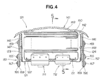
Fig. 4 is an enlarged cross-sectional view taken along line 4-4 ofFig. 1 ; -
Fig. 5 is a cross-sectional view taken along line 5-5 ofFig. 4 ; -
Fig. 6 is a perspective view of the air bag module shown inFig. 2 ; -
Fig. 7 is a view illustrating function of lid restricting means of the air bag module shown inFig. 6 ; -
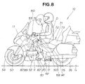
Fig. 8 is a view illustrating function of the air bag apparatus according toEmbodiment 1 of the present invention; -
Fig. 9 is a view illustrating structure and function of lid restricting means of an air bag module according to Embodiment 2 of the present invention; -
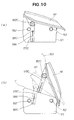
Fig. 10 is a view illustrating structure and function of an air bag module according to Embodiment 3 of the present invention; -
Fig. 11 is a perspective view of an air bag module according to Embodiment 4; and -
Fig. 12 is a view illustrating function of the air bag module shown inFig. 11 . - Certain preferred embodiments of the present invention are described below with reference to the accompanying drawings.
- Referring to
Fig. 1 , amotorcycle 10, which is a saddle-ride type vehicle, includes aheadpipe 11. Avehicle body frame 12 extends rearward. - The
vehicle body frame 12 includes theheadpipe 11 forming a front part of avehicle body 14, amain frame 15 extending rearward from theheadpipe 11, and a pivot plate 17 attached to a rear end of themain frame 15 and carrying apivot shaft 16. Thevehicle body frame 12 further includes aseat rail 18 extending upward and rearward from a top of the pivot plate 17, and a middle frame 19 interconnecting a rear end of theseat rail 18 and a middle of the pivot plate 17 and supporting theseat rail 18. Theseat rail 18 forms a rear part of thevehicle body frame 12. Attached to a bottom of the pivot plate 17 is afootrest 20 for a rider's foot to rest on. - A sub-rail 21 extends rearward from an upper end of the middle frame 19. The sub-rail 21 has its rear part connected to the middle frame 19 through a
seat stay 22. Anauxiliary stay 23 extends downward and rearward from a rear part of theseat stay 22, and then runs horizontally. Mounted on the sub-rail 21 is atrunk 27 for storing articles. Thetrunk 27 has itsfront wall 27a to which is attached abackrest 28 for supporting a back of a rider. - It will be understood that respective ones of the
main frame 15, the pivot frame 17, theseat rail 18, the middle frame 19, thestep 20, the sub-rail 21, theseat stay 22 and theauxiliary stay 23 are symmetrically provided on opposite sides of themotorcycle 10. - An
engine 32 is fixed below themain frame 15 withfasteners 31a to 31c. Theengine 32 is, for example, a flat-six, water-cooled engine. - Mounted to the pivot plate 17 is a
rear swing arm 34 pivotable vertically on thepivot shaft 16. Therear swing arm 34 has its rear end to which is attached arear axle 35. Arear wheel 36 is rotationally attached to therear axle 35. Mounted to therear wheel 36 is a drivensprocket 41. Theengine 32 has adrive shaft 37 to which is attached adrive sprocket 38. Therear wheel 36 is driven by achain 42 extending around thesprockets - The
rear swing arm 34 carries alink mechanism 47 to which is attached a lower end of arear cushion unit 48. Therear cushion unit 48 has its upper end attached to abracket 49 disposed near themain frame 15. - Attached to the
headpipe 11 is a steerablefront folk 52. Thefront folk 52 carries afront axle 53. Afront wheel 54 is rotationally attached to thefront axle 53. Thefront folk 53 has its upper end to which is mounted asteering handle 55 supported by theheadpipe 11. - Provided on a side of a front part of the
main frame 15 is amain cowl 56 having anopening 57 formed at a side thereof. Aradiator unit 58 for cooling theengine 32 is positioned facing theopening 57. - Disposed above the
front wheel 54 is a front fender 66. Afront disc plate 62 is integral with thefront wheel 54. Thefront folk 52 carries a frontdisc brake unit 61 for sandwiching thefront disc plate 62. - Located forward of the
headpipe 11 is afront cowl 63 covering a front part of themotorcycle 10. Afront shield 64 extends from a top of thefront cowl 63. Provided at a lower end of the pivot plate 17 is amain stand bracket 68. A main stand 69 is attached to themain stand bracket 68. Abattery 67 is disposed below a rider'sseat 71 for a rider to sit on. Ameter 70 is disposed rearward of thefront shield 64. - The
seat 71 is disposed on theseat rail 18. Theseat 71 includes afront seat portion 72 and arear seat portion 73 disposed rearward of and contiguous with thefront seat portion 72. - An air bag apparatus 86 includes an
air bag module 82 and an air bag control unit 87 for controlling deployment of an air bag 150 (Fig. 4 ) stored in theair bag module 82. - The
air bag module 82 is disposed proximate theseat 71. Theair bag module 82 includes aretaining box 121, which is a case. Theretaining box 121 is disposed directly forward of theseat 71. - Disposed at top and bottom portions of the
front folk 52 are first andsecond sensors vehicle body 14. A first cable 79 extends from the top andbottom sensors engine 32 and is connected to the air bag control unit 87. Themeter 70 includes anindicator 80 for indicating whether the air bag apparatus 86 is in a normal or abnormal state. Asecond cable 85 extends from theindicator 80. Thesecond cable 85 is connected to the air bag control unit 87. A third cable 88 extends from thebattery 67. The third cable 88 extends below theseat 71 and is connected to the air bag control unit 87. It will be noted that each of the first sensor, thesecond sensor 78, and the first cable 79 is provided in pairs on left and right folk parts of thefront folk 52. - The
air bag module 82 storing an inflator and the air bag will be discussed below with reference toFigs. 2 and 3. Fig. 2 shows in top plan theair bag module 82 with a lid and the air bag removed.Fig. 3 shows in bottom plan theair bag module 82. - Turning to
Fig. 2 , the inflator is provided in pairs. That is, aleft inflator 111 is disposed on a left side of themotorcycle 10 while aright inflator 112 is disposed on a right side of themotorcycle 10. Theleft inflator 111 produces gas whose amount is different from that produced by theright inflator 112. Theleft inflator 111 is greater in size than theright inflator 112 in order that theleft inflator 111 provides more gas than theright inflator 112 does. Theleft inflator 111 includes anouter wall 113 having amount flange 115 projecting outward from theouter wall 113. Theright inflator 112 includes anouter wall 114 having amount flange 116 projecting outward from theouter wall 114. - The
retaining box 121 includes abottom plate 122, left andright walls bottom plate 122, and front andrear walls bottom plate 122. Thebottom plate 122 has left andright openings lower parts inflators openings right inflators openings bottom plate 122 with anair bag ring 131 clamping themount flanges bottom plate 122. - Turning to
Fig. 3 , thelower part 133 of the left inflator is fitted in theleft opening 127 of thebottom plate 122. Thelower part 134 of the right inflator is fitted in theright opening 128 of thebottom plate 122. -
Nuts 136 are tightened onto eightscrews 135 to attach the left andright inflators retaining box 121 with themount flanges 115, 116 (Fig. 2 ) firmly sandwiched between thebottom plate 122 and the air bag ring 131 (Fig. 2 ). - Reference is made to
Fig. 4 . Alid 141 is arranged to close an upwardly openingportion 142 of the retainingportion 121. Thelid 141 includes acover portion 143 for covering theopening portion 142. Thelid 141 further includes a leftvertical wall 145 extending downward from a vicinity of a left end of thecover portion 143, and a rightvertical wall 146 extending downward from a vicinity of a right end of thecover portion 143. The leftvertical wall 145 is attached to theleft wall 123 of theretaining box 121 and the rightvertical wall 124 is attached to theright wall 124 of theretaining box 121. - The left
vertical wall 145 has a fragile portion 147 having a half height of the overall height of thewall 145 for allowing the leftvertical wall 145 to cut along the fragile portion 147 during deployment of theair bag 150. The rightvertical wall 146 has afragile portion 148 having a half height of the overall height of thewall 146 for allowing the rightvertical wall 146 to cut along thefragile portion 148 during deployment of theair bag 150. The deployment of theair bag 150 cuts thelid 141 along thefragile portions 147, 148 to cut an upper side of thelid 141 away from theretaining box 121. - A
left link mechanism 151 is disposed outside the leftvertical wall 145 for restricting an angle through which thelid 141 pivots away from theopening portion 142 during deployment of theair bag 150. Aright link mechanism 152 is disposed outside the rightvertical wall 146 for restricting an angle through which thelid 141 pivots away from theopening portion 142 during deployment of theair bag 150. - As shown in
Fig. 5 , thelid 141 includes a frontvertical wall 155 extending downward from afront end 153 of thecover portion 143, and a rearvertical wall 156 extending downward from arear end 154 of thecover portion 143. The frontvertical wall 155 is attached to thefront wall 125 of theretaining box 121. The rearvertical wall 156 is attached to therear wall 126 of theretaining box 121. - The front
vertical wall 155 has a frontfragile portion 157 having a half height of the overall height of thewall 155 for allowing the frontvertical wall 155 to cut along the frontfragile portion 157 when theair bag 150 is deployed to cause thelid 141 to pivot away from theopening portion 142. The rearvertical wall 156 has ahinge portion 158 having a half height of the overall height of thewall 156. The deployment of theair bag 150 causes thelid 141 to pivot on thehinge portion 158 away from theopening portion 142. Thehinge portion 158 is formed at a rear side of thelid 141. - A
lid stay 161 extends transversely of thecover portion 143 of thelid 141. Thelid stay 161 is insert-molded into thecover portion 143 of thelid 141. Thelid stay 161 is made of metal. Thelid 141 is made of resin. Thelid 141 is affixed to a rear side of theretaining box 121 byplural rivets 162. - Referring to
Fig. 6 , theleft link mechanism 151 includes afirst pivot 165 attached to theleft wall 123 of theretaining box 121, afirst link 166 extending rearward from thefirst pivot 165, asecond pivot 167 provided at a distal end portion of thefirst link 166, asecond link 168 extending upward and forward from thesecond pivot 167, and athird pivot 169 provided at adistal end portion 174 of thesecond link 168 and attached to thelid stay 161. It is to be understood that theright link mechanism 152 has the same structure as that of theleft link mechanism 151, and hence discussion of theright link mechanism 152 will be omitted. - The
lid stay 161 includes ahorizontal arm 173, a leftvertical arm 171 extending downward from a left end of thehorizontal arm 173, and a rightvertical arm 172 extending downward from a right end of thehorizontal arm 173. To the left and rightvertical arms third pivots distal end portions second link 168 are attached to thethird pivots second link 168. - The
air bag module 82 includes theretaining box 121 and the air bag 150 (Fig. 4 ) stored in theretaining box 121. When inflated, theair bag 150 is deployed forward of a rider sitting on theseat 71. Theair bag module 82 includes thelid 141 closing the opening portion 142 (Fig. 4 ) of theretaining box 121. Thelid 141 has the hinge portion 158 (Fig. 5 ) formed on the rear side thereof for allowing thelid 141 to pivot on thehinge portion 158 away from theopening portion 142 during deployment of theair bag 150. Theair bag module 82 further includes the left andright link mechanisms lid 141 and theretaining box 121. Thelink mechanisms lid 141 pivots away from theopening portion 142. - The
lid stay 161 is integral with thelid 141. Thelink mechanisms vertical arms lid stay 161. Thehorizontal arm 173 is integral with the left and rightvertical arms lid stay 161 has a U-shape and interconnects the left andright link mechanisms vertical arms horizontal arm 173, allow for even dispersion of impact from thelink mechanisms lid 141 when thelid 141 pivots away from theopening portion 142. - Description will be made as to functions of the foregoing air bag apparatus in
Embodiment 1. - Turning to
Fig. 7(a) , theretaining box 121 is closed by thelid 141. Thelink mechanism 151 is disposed between thelid 141 and theretaining box 121. - Referring to
Fig. 7(b) , as theair bag 150 is deployed, thelid 141 pivots away from the opening portion of theretaining box 121 to bring thefirst link 166 and thesecond link 168 into alignment. - If no link mechanism for limiting an angle through which the
lid 141 pivots away from the opening portion of theretaining box 121 were disposed between the retainingbox 121 and thelid 141, it would be difficult to control theair bag 150 to be deployed forward and upward. - The present invention provides the
link mechanisms box 121 and thelid 141, as discussed above. Thelink mechanisms lid 141 to pivot away from the opening portion of the retaining box through alimited angle θ 1, such that, when inflated, theair bag 150 is deployed upward to a limited extent but forward of a rider freely. The air bag, which is deployed upward to a limited extent but forward freely, can be in a desired position. More specifically, theair bag 150 can be deployed in a direction suitable for a rider who has been forced to shift forward when undergoing impact. - The
angle θ 1 is defined as an angle through which thelid 141 pivots on thehinge portion 158 relative to thebottom plate 122 of theretaining box 121. Theangle θ 1 is set to be 70 degrees inEmbodiment 1. It will be understood that theangle θ 1 is not limited to 70 degrees but may be changed. - During the pivotal movement of the
lid 141 away from theopening portion 142 of theretaining box 121, thefirst link 166 comes into alignment with thesecond link 168. The first andsecond links air bag 150 from being deployed outward of thelinks air bag 150 to allow theair bag 150 to be deployed toward a desired region. - The
lid stay 161, which is highly likely to undergo a force, is made from metal. Thelid 141 for closing theretaining box 121 is made of resin. Provision of themetal lid stay 161 and theresin lid 141 results in lightweightair bag module 82 having required strength. In addition, it is easy to form thefragile portions 147, 148, 157 (Figs. 4 and5 ) on thelid 141 because thelid 141 is made of resin. - Reference is made to
Fig. 8 . Theair bag module 82 is shown carried on themotorcycle 10. Theair bag module 82 is designed such that thelid 141 can pivot through an angle θ 2 not exceeding 90 degrees relative to a road surface G. A direction of deployment of theair bag 150 when a rider D sits on theseat 71 is determined depending upon values of theangles θ 1, θ 2. - If the angle θ 2 is set to be more than 90 degrees, the air bag may be deployed rearward.
- In
Embodiment 1, the angle θ 2 is set not to exceed 90 degrees relative to the road surface G. This makes it possible for theair bag 150 to be deployed toward a region extending from a forward region located forward of the retaining box to an upward region located above the retaining box. That is, theair bag 150 is deployed forward and upward as the rider D is forced to move forward. - When viewed in side elevation, the air bag control unit 87 is located between the
headpipe 11 and theair bag module 82. The air bag control unit 87 includes a delay means 189 for igniting the left andright inflators - The
left inflator 111 generates a different amount of gas than that of theright inflator 112. Use of theseinflators - Generally, air bags used in saddle-ride type is greater in capacity than those used in four-wheeled vehicles. Conventionally, it is therefore necessary to use inflators providing large outputs so as to inflate the air bags of the saddle-type vehicles. Such inflators of large outputs require large space.
- In
Embodiment 1, the left andright inflators inflators air bag 150. - An air bag apparatus in Embodiment 2 will be described below with reference to
Fig. 9(a) and Fig. 9(b) . - As shown in
Fig. 9(a) , theretaining box 121 is closed by thelid 141. Between thelid 141 and theretaining box 121 is disposed astrip 177B (webbing) providing lid restricting means for restricting an angle through which thelid 141 pivots away from theretaining box 121. Thestrip 177B is attached to theretaining box 121 by afastener 181 and to the lid stay (shown at 161 inFig. 5 ) by anotherfastener 182. Thestrip 177B has acollapsible portion 184 at anintermediate part 183 thereof. Thecollapsible portion 184 is folded up and has its length set to allow thelid 141 to pivot through a predetermined angle. Thefasteners strip 177B are each provided in pairs. The respective pairs of thefasteners 181 and thestrips 177B are located on left and right sides of theretaining box 121. The pair of thefasteners 182 is located on left and right sides of the lid stay. - Reference is made to
Fig. 9(b) . Deployment of theair bag 150 causes thelid 141 to pivot away from theretaining box 121. The pivotal movement of thelid 141 brings thecollapsible portion 184 to an unfolded position in which thecollapsible portion 184 is straightened out. Thestrip 177B helps reduce the number of components of the air bag apparatus, unlike, for example, a multi-piece mechanism. The reduction in the number of components of the air bag apparatus results in reduction in the cost for the apparatus. Thestrip 177B has its function similar to that of the link mechanism inEmbodiment 1. - An air bag apparatus in Embodiment 3 will be described below with reference to
Fig. 10(a) and Fig. 10(b) . - As can be seen from
Fig. 10(a) , the air bag apparatus in Embodiment 3 significantly differs from the air bag apparatus in Embodiment 2 in that afastener 181C is disposed on theretaining box 121 at a level higher than thefastener 181 and retains one end of a longitudinally extending fragile portion or slit 186 of astrip 177C. The air bag apparatus in Embodiment 3 is similar to the air bag apparatus in Embodiment 2 in other respects. - Reference is made to
Fig. 10(b) . Thelid 141 pivots away from theretaining box 121 through a predetermined angle during deployment of theair bag 150, allowing thefastener 181C to break thestrip 177C along theslit 186. Finally, thestrip 177C is torn away from thefastener 181C. Namely, thestrip 177C, which is broken by and torn away from thefastener 181C, slows down the pivotinglid 141, directing theair bag 150 to be deployed in such a direction as to support a rider. - An air bag apparatus in Embodiment 4 will be described below with reference to
Fig. 11 . - As shown in
Fig. 11 , a single strip (webbing) 177D, which is lid restricting means for restricting an angle through which thelid 141 pivots away from theretaining box 121, is fastened byfasteners right walls retaining box 121. A sheet-shapedstay 188 is insert-molded into thelid 141. A plurality of ring-shapedfrictional guide members 187 extend from thestay 188. Thestrip 177D extends through thefrictional guide members 187. - The
strip 177D has acollapsible portion 184D which is shown folded at a middle of the length thereof. Theportion 184D, which is folded, is capable of being unfolded when thelid 141 pivots away from theretaining box 121. Thestrip 177D is arranged to be guided by thefrictional guide members 187 disposed along a back side of thelid 141. Thestrip 177D restricts thelid 177D from pivoting away from theretaining box 121 through more than a predetermined angle. Thestrip 177D has its length set in correspondence to a predetermined angle through which thelid 141 pivots away from theretaining box 121. The number of thefrictional guide members 187 is four, and these fourguide members 187 are attached to thelid 141 for slowing down thestrip 177D traveling through theguide members 187 so as to retard pivotal movement of thelid 141 away from theretaining box 121 through a predetermined angle. - The
strip 177D helps reduce the number of components of the air bag apparatus, unlike, for example, a multi-piece mechanism. The reduction in the number of components of the air bag apparatus results in reduction in the cost for the apparatus. - Description will be made as to function of the air bag apparatus shown in
Fig. 11 in Embodiment 4 with reference toFig. 12 . - As shown in
Fig. 12(a) , theretaining box 121 is closed by thelid 141 with theportion 184D of thestrip 177D folded. As theair bag 150 is deployed, thelid 141 begins to pivot away from theretaining box 121 causing theportion 184D of thestrip 177D to be unfolded gradually. As theportion 184D is unfolded, thestrip 177D slows down by traveling frictionally through thefrictional guide members 187, such that a speed of the pivotal movement of thelid 141 is reduced. - Turning to
Fig. 12(b) , thelid 141 is fully pivoted with thestrip 177D unfolded after the air bag (not shown) has been deployed. It will be noted that the number of the frictional guide members may be optionally set number such as two, three, five or other number. - The present invention has been described as being applied to the motorcycle but is applicable to a three-wheeled vehicle or a saddle-ride vehicle.
- The present invention is suitable for a motorcycle.
-
- 10 a saddle-type vehicle
- 12 a vehicle body frame
- 71 a rider's seat
- 86 an air bag apparatus
- 121 a retaining box
- 141 a lid
- 142 an opening portion
- 150 an air bag
- 151 lid restricting means (left link mechanism)
- 152 lid restricting means (right link mechanism)
- 158 a hinge portion
- 161 a lid stay
- 171 a left lid stay (left vertical arm)
- 172 right lid stay (right vertical arm)
- 177, 177B, 177C, 177D lid restricting means (strips)
- 181 a fastener
- 186 a fragile portion (slit)
- 187 a guide member (frictional guide member)
Claims (8)
- An air bag apparatus for a saddle-ride type vehicle, comprising:a retaining box disposed on a vehicle body of the vehicle and located directly forward of a rider's seat;an air bag stored in the retaining box and configured to be deployed forward of a rider;a lid for closing an opening portion of the retaining box, the lid having a hinge portion formed on a rear side thereof for allowing the lid to pivot on the hinge portion during deployment of the air bag; andlid restricting means disposed between the lid and the retaining box for restricting an angle through which the lid pivots on the hinge portion away from the opening portion of the retaining box.
- The apparatus of claim 1, further comprising left and right lid stays integral with the lid, the lid restricting means being provided at each of the lid stays.
- The apparatus of claim 1, wherein the lid restricting means comprises a link mechanism.
- The apparatus of claim 1, wherein the lid restricting means comprises a strip.
- The apparatus of claim 2, wherein the lid stays are insert-molded into the lid.
- The apparatus of claim 1, wherein the lid restricting means restricts the angle to less than 90 degrees relative to a road surface with the air bag apparatus carried on the vehicle.
- The apparatus of claim 4, wherein the strip includes a fragile portion formed longitudinally thereof, the apparatus further comprising a fastener holding one end of the fragile portion to the retaining box, the lid being pivotable away from the opening portion through a predetermined angle while allowing the fastener to break the fragile portion.
- The apparatus of claim 4, wherein the strip extends inside the lid and between left and right sides of the lid, the apparatus further comprising a guide member disposed inside the lid and retaining the strip, the lid being pivotable away from the opening portion through a predetermined angle while allowing the strip to travel between the lid and the guide member.
Applications Claiming Priority (2)
| Application Number | Priority Date | Filing Date | Title |
|---|---|---|---|
| JP2009145709A JP2011000962A (en) | 2009-06-18 | 2009-06-18 | Airbag device of saddle-riding type vehicle |
| PCT/JP2010/060307 WO2010147186A1 (en) | 2009-06-18 | 2010-06-17 | Airbag device for straddle type vehicles |
Publications (3)
| Publication Number | Publication Date |
|---|---|
| EP2444306A1 true EP2444306A1 (en) | 2012-04-25 |
| EP2444306A4 EP2444306A4 (en) | 2013-01-16 |
| EP2444306B1 EP2444306B1 (en) | 2014-03-12 |
Family
ID=43356503
Family Applications (1)
| Application Number | Title | Priority Date | Filing Date |
|---|---|---|---|
| EP10789560.9A Not-in-force EP2444306B1 (en) | 2009-06-18 | 2010-06-17 | Airbag device for straddle type vehicles |
Country Status (5)
| Country | Link |
|---|---|
| US (1) | US8550491B2 (en) |
| EP (1) | EP2444306B1 (en) |
| JP (1) | JP2011000962A (en) |
| BR (1) | BRPI1012746B1 (en) |
| WO (1) | WO2010147186A1 (en) |
Cited By (1)
| Publication number | Priority date | Publication date | Assignee | Title |
|---|---|---|---|---|
| FR3001681A1 (en) * | 2013-02-06 | 2014-08-08 | Faurecia Interieur Ind | Retaining device for flap utilized for closing case of inflatable cushion in fascia of car, has damping element placed between parts of support element, and restraint element in support against damping element at time of opening of flap |
Families Citing this family (14)
| Publication number | Priority date | Publication date | Assignee | Title |
|---|---|---|---|---|
| JP5634314B2 (en) | 2011-03-31 | 2014-12-03 | タカタ株式会社 | Airbag device |
| JP5604353B2 (en) | 2011-03-31 | 2014-10-08 | タカタ株式会社 | Airbag device and airbag cover |
| JP5767992B2 (en) * | 2011-03-31 | 2015-08-26 | タカタ株式会社 | Airbag device |
| JP6236659B2 (en) * | 2013-02-28 | 2017-11-29 | 本田技研工業株式会社 | Saddle riding vehicle |
| US10457241B2 (en) * | 2016-10-28 | 2019-10-29 | Ford Global Technologies, Llc | Airbag assembly including a deflector |
| CN107651049A (en) * | 2017-11-09 | 2018-02-02 | 徐来 | A kind of safety guard for being exclusively used in child's bicycle exercise |
| JP6689894B2 (en) | 2018-01-15 | 2020-04-28 | 本田技研工業株式会社 | Vehicle airbag device |
| JP7089585B2 (en) * | 2018-04-27 | 2022-06-22 | 本田技研工業株式会社 | Airbag device for saddle-riding vehicles |
| JP7296468B2 (en) * | 2019-09-30 | 2023-06-22 | 本田技研工業株式会社 | Airbag device for saddle type vehicle |
| US11247632B2 (en) * | 2019-10-07 | 2022-02-15 | Ford Global Technologies, Llc | Airbag assembly with releasable panel |
| EP4079583B1 (en) * | 2019-12-18 | 2025-05-14 | Autoliv Development AB | Airbag module |
| JP7066763B2 (en) * | 2020-01-16 | 2022-05-13 | 本田技研工業株式会社 | Saddle-type vehicle |
| JP2024143267A (en) * | 2023-03-30 | 2024-10-11 | Joyson Safety Systems Japan合同会社 | Airbag device and saddle-type vehicle equipped with airbag device |
| US12434659B1 (en) * | 2024-05-20 | 2025-10-07 | Toyoda Gosei Co., Ltd. | Vehicle airbag module including tethered deployment guide |
Family Cites Families (53)
| Publication number | Priority date | Publication date | Assignee | Title |
|---|---|---|---|---|
| US5072967A (en) * | 1990-07-12 | 1991-12-17 | Davidson Textron Inc. | Instrument panel with invisible airbag deployment door |
| US5306042A (en) * | 1992-07-06 | 1994-04-26 | General Motors Corporation | Air bag depolyment control |
| DE4227528C1 (en) * | 1992-08-20 | 1993-12-23 | Daimler Benz Ag | Arrangement of an inflatable passenger crash protection |
| US5308111A (en) * | 1993-01-29 | 1994-05-03 | General Motors Corporation | Inflatable restraint having an improved tether |
| US5360231A (en) * | 1993-08-02 | 1994-11-01 | Milliken Research Corporation | Rotatable occupant restraint |
| US5385366A (en) * | 1993-09-07 | 1995-01-31 | General Motors Corporation | Air bag deflection shield |
| US6053527A (en) * | 1994-08-05 | 2000-04-25 | Autoliv Asp, Inc. | Airbag system with serviceable tethered cover |
| US5460401A (en) * | 1994-08-05 | 1995-10-24 | Morton International, Inc. | Airbag system with tethered cover |
| US5474324A (en) * | 1994-11-07 | 1995-12-12 | Morton International | Tethered cover airbag system |
| US5533746A (en) * | 1995-01-18 | 1996-07-09 | Morton International, Inc. | Tethered cover for a panel opening in an air bag inflator system |
| DE29508063U1 (en) * | 1995-05-16 | 1995-09-14 | Trw Repa Gmbh, 73553 Alfdorf | Cover for an airbag restraint system |
| US5613701A (en) * | 1995-05-16 | 1997-03-25 | Morton International Inc. | Break-away fastening system for air bag deployment doors |
| JPH09156555A (en) * | 1995-12-05 | 1997-06-17 | Shiroki Corp | Retractable front basket for compact vehicle |
| US5651562A (en) * | 1996-02-28 | 1997-07-29 | Trw Inc. | Release mechanism |
| JP3685872B2 (en) | 1996-06-11 | 2005-08-24 | 本田技研工業株式会社 | Pressure adjusting device for air bag in motorcycle |
| JP3685873B2 (en) * | 1996-06-19 | 2005-08-24 | 本田技研工業株式会社 | Airbag device for motorcycle |
| JP3592447B2 (en) * | 1996-07-25 | 2004-11-24 | 本田技研工業株式会社 | Airbag device for motorcycles |
| GB9625395D0 (en) * | 1996-12-06 | 1997-01-22 | Ford Motor Co | Improvements relating to airbag door tethering devices |
| US5899488A (en) * | 1997-03-26 | 1999-05-04 | Inova Gmbh Technische Entwicklungen | Air bag arrangement and triggering process therefor |
| US6082760A (en) * | 1997-04-18 | 2000-07-04 | Toyota Jidosha Kabushiki Kaisha | Air bag apparatus for passenger seat |
| US5941558A (en) * | 1997-06-09 | 1999-08-24 | Textron Automotive Company Inc. | Apparatus for deploying an airbag through a hard panel |
| DE69828967D1 (en) * | 1997-06-09 | 2005-03-17 | Textron Automotive Co Inc | DEVICE FOR DEPLOYING A AIR BAG THROUGH A FIXED FAIRING PART |
| US6457738B1 (en) * | 1997-06-09 | 2002-10-01 | Textron Automotive Company, Inc. | Inflatable restraint apparatus |
| US6955376B1 (en) * | 1997-06-09 | 2005-10-18 | Collins & Aikman Products Co. | Apparatus for deploying an air bag through a hard panel |
| US6203056B1 (en) * | 1997-06-09 | 2001-03-20 | Textron Automotive Company Inc. | Apparatus for deploying an airbag through a hard panel |
| DE29711679U1 (en) * | 1997-07-03 | 1997-10-30 | Trw Occupant Restraint Systems Gmbh, 73551 Alfdorf | Airbag module |
| US6024377A (en) * | 1997-09-22 | 2000-02-15 | Breed Automotive Technology, Inc. | Low mount airbag deployment system |
| US5947512A (en) * | 1997-10-20 | 1999-09-07 | Trw Inc. | Tethered horn switch for air bag module |
| DE19958865B4 (en) * | 1999-12-07 | 2009-11-12 | Peguform Gmbh | An airbag cover device and device and method for producing an airbag cover device |
| DE29922987U1 (en) * | 1999-12-30 | 2000-05-11 | TRW Occupant Restraint Systems GmbH & Co. KG, 73553 Alfdorf | Airbag module |
| DE50103405D1 (en) * | 2000-04-27 | 2004-09-30 | Volkswagen Ag | AIRBAG DEVICE AND OPERATING METHOD THEREFOR |
| EP1151898B1 (en) * | 2000-04-28 | 2004-02-25 | Inoac Corporation | Tear structure of air bag door |
| JP3701579B2 (en) * | 2000-09-22 | 2005-09-28 | 本田技研工業株式会社 | Vehicle article storage structure |
| DE10105459A1 (en) * | 2001-02-07 | 2002-08-08 | Bayerische Motoren Werke Ag | Upper-body restraint for use on motorcycles for accident safety, has gasbag to be inflated by a generator and fitted on a motorcycle bodywork part like a fuel tank in front of the rider |
| JP2004520229A (en) * | 2001-02-12 | 2004-07-08 | ザイ・オートモーテイブ・ザル・ゲゼルシヤフト・ミツト・ベシユレンクテル・ハフツング | Apparatus and method for covering an airbag |
| DE10117830A1 (en) * | 2001-04-10 | 2003-06-05 | Bayerische Motoren Werke Ag | An air bag assembly |
| DE10204333B9 (en) * | 2002-02-01 | 2005-07-21 | Peguform Gmbh & Co. Kg | Retraction mechanism for the lining of an airbag system |
| JP4129138B2 (en) * | 2002-03-06 | 2008-08-06 | 本田技研工業株式会社 | Airbag device for motorcycle |
| US6719320B2 (en) * | 2002-03-27 | 2004-04-13 | Collins & Aikman Automotive Company, Inc. | Controlled tether arrangement for an airbag |
| DE10316542B4 (en) * | 2002-04-11 | 2011-08-11 | Toyoda Gosei Co., Ltd. | An air bag device for a vehicle and method for deploying an air bag |
| JP4084592B2 (en) * | 2002-04-18 | 2008-04-30 | 本田技研工業株式会社 | Airbag device in scooter type vehicle |
| US7380821B2 (en) * | 2004-01-27 | 2008-06-03 | Takata Corporation | Passenger protection apparatus |
| US7210700B2 (en) * | 2004-08-24 | 2007-05-01 | Visteon Global Technologies, Inc | Hinge mechanism for inflatable restraint apparatus |
| EP1661799B1 (en) | 2004-11-30 | 2008-05-14 | Honda Access Corporation | Trunk and trunk device for motorcycle |
| JP4217206B2 (en) * | 2004-11-30 | 2009-01-28 | 株式会社ホンダアクセス | Motorcycle trunk |
| US7789416B2 (en) * | 2005-09-08 | 2010-09-07 | Honda Motor Co., Ltd. | Air bag module cover structure |
| US7578516B2 (en) * | 2005-09-09 | 2009-08-25 | Honda Motor Co., Ltd. | Air bag support belt storing structure |
| JP4737529B2 (en) * | 2005-10-18 | 2011-08-03 | 本田技研工業株式会社 | Airbag support belt cover structure |
| JP4679376B2 (en) * | 2006-01-25 | 2011-04-27 | タカタ株式会社 | Motorcycle airbag device, motorcycle |
| JP4702842B2 (en) * | 2006-02-14 | 2011-06-15 | 本田技研工業株式会社 | Airbag module for vehicles |
| JP4766564B2 (en) * | 2006-09-29 | 2011-09-07 | 本田技研工業株式会社 | Motorcycle airbag device |
| US8408588B2 (en) * | 2008-03-19 | 2013-04-02 | Johnson Controls Technology Company | Fixture having airbag outlet flap |
| FR2941194B1 (en) * | 2009-01-21 | 2011-02-18 | Faurecia Interieur Ind | ARRANGEMENT OF INFLATABLE SAFETY CUSHION SHUTTER JOINED ON A DASHBOARD |
-
2009
- 2009-06-18 JP JP2009145709A patent/JP2011000962A/en active Pending
-
2010
- 2010-06-17 EP EP10789560.9A patent/EP2444306B1/en not_active Not-in-force
- 2010-06-17 US US13/203,245 patent/US8550491B2/en active Active
- 2010-06-17 BR BRPI1012746-1A patent/BRPI1012746B1/en not_active IP Right Cessation
- 2010-06-17 WO PCT/JP2010/060307 patent/WO2010147186A1/en not_active Ceased
Cited By (1)
| Publication number | Priority date | Publication date | Assignee | Title |
|---|---|---|---|---|
| FR3001681A1 (en) * | 2013-02-06 | 2014-08-08 | Faurecia Interieur Ind | Retaining device for flap utilized for closing case of inflatable cushion in fascia of car, has damping element placed between parts of support element, and restraint element in support against damping element at time of opening of flap |
Also Published As
| Publication number | Publication date |
|---|---|
| WO2010147186A1 (en) | 2010-12-23 |
| BRPI1012746A2 (en) | 2016-03-22 |
| BRPI1012746B1 (en) | 2019-10-15 |
| JP2011000962A (en) | 2011-01-06 |
| US8550491B2 (en) | 2013-10-08 |
| US20110309602A1 (en) | 2011-12-22 |
| EP2444306A4 (en) | 2013-01-16 |
| EP2444306B1 (en) | 2014-03-12 |
Similar Documents
| Publication | Publication Date | Title |
|---|---|---|
| EP2444306B1 (en) | Airbag device for straddle type vehicles | |
| JP4084592B2 (en) | Airbag device in scooter type vehicle | |
| JP2003327182A (en) | Scooter-type motorcycle airbag device | |
| EP3753827A1 (en) | Air bag device for saddled vehicle | |
| JP7089585B2 (en) | Airbag device for saddle-riding vehicles | |
| JP2004338658A (en) | Airbag device | |
| EP2075165B1 (en) | Low-floor type vehicle with airbag | |
| EP1634803B1 (en) | Rider restraining device for two wheel vehicle | |
| EP2075182B1 (en) | Saddle-ride type vehicle with airbag | |
| JP5222219B2 (en) | Saddle riding vehicle | |
| JP5399139B2 (en) | Airbag device for saddle riding type vehicle | |
| US7900955B2 (en) | Airbag device | |
| JP5371536B2 (en) | Saddle riding vehicle | |
| JP4519167B2 (en) | Saddle riding | |
| JP6945066B2 (en) | Airbag device for saddle-riding vehicles | |
| US20140015232A1 (en) | Airbag apparatus and airbag cover | |
| JP6236659B2 (en) | Saddle riding vehicle | |
| EP3828065B1 (en) | Saddle riding type vehicle comprising an airbag device | |
| JP5297908B2 (en) | Airbag device | |
| JPWO2019207778A1 (en) | Airbag device for saddle-riding vehicles | |
| JP2011000968A (en) | Airbag device | |
| JPH04372438A (en) | Arrangement structure of assist grip for automobile | |
| TH58930A (en) | Motorcycle air bag device | |
| TH38107B (en) | Motorcycle air bag device |
Legal Events
| Date | Code | Title | Description |
|---|---|---|---|
| PUAI | Public reference made under article 153(3) epc to a published international application that has entered the european phase |
Free format text: ORIGINAL CODE: 0009012 |
|
| 17P | Request for examination filed |
Effective date: 20111213 |
|
| AK | Designated contracting states |
Kind code of ref document: A1 Designated state(s): AL AT BE BG CH CY CZ DE DK EE ES FI FR GB GR HR HU IE IS IT LI LT LU LV MC MK MT NL NO PL PT RO SE SI SK SM TR |
|
| DAX | Request for extension of the european patent (deleted) | ||
| A4 | Supplementary search report drawn up and despatched |
Effective date: 20121214 |
|
| RIC1 | Information provided on ipc code assigned before grant |
Ipc: B62J 27/00 20060101AFI20121210BHEP Ipc: B60R 21/215 20110101ALI20121210BHEP Ipc: B60R 21/216 20110101ALI20121210BHEP |
|
| GRAP | Despatch of communication of intention to grant a patent |
Free format text: ORIGINAL CODE: EPIDOSNIGR1 |
|
| RIC1 | Information provided on ipc code assigned before grant |
Ipc: B62J 27/00 20060101AFI20130717BHEP Ipc: B60R 21/216 20110101ALI20130717BHEP Ipc: B60R 21/215 20110101ALI20130717BHEP |
|
| INTG | Intention to grant announced |
Effective date: 20130821 |
|
| GRAS | Grant fee paid |
Free format text: ORIGINAL CODE: EPIDOSNIGR3 |
|
| GRAA | (expected) grant |
Free format text: ORIGINAL CODE: 0009210 |
|
| AK | Designated contracting states |
Kind code of ref document: B1 Designated state(s): AL AT BE BG CH CY CZ DE DK EE ES FI FR GB GR HR HU IE IS IT LI LT LU LV MC MK MT NL NO PL PT RO SE SI SK SM TR |
|
| REG | Reference to a national code |
Ref country code: GB Ref legal event code: FG4D |
|
| REG | Reference to a national code |
Ref country code: CH Ref legal event code: EP |
|
| REG | Reference to a national code |
Ref country code: AT Ref legal event code: REF Ref document number: 656085 Country of ref document: AT Kind code of ref document: T Effective date: 20140315 |
|
| REG | Reference to a national code |
Ref country code: IE Ref legal event code: FG4D |
|
| REG | Reference to a national code |
Ref country code: DE Ref legal event code: R096 Ref document number: 602010014292 Country of ref document: DE Effective date: 20140424 |
|
| REG | Reference to a national code |
Ref country code: NL Ref legal event code: VDEP Effective date: 20140312 |
|
| PG25 | Lapsed in a contracting state [announced via postgrant information from national office to epo] |
Ref country code: LT Free format text: LAPSE BECAUSE OF FAILURE TO SUBMIT A TRANSLATION OF THE DESCRIPTION OR TO PAY THE FEE WITHIN THE PRESCRIBED TIME-LIMIT Effective date: 20140312 Ref country code: NO Free format text: LAPSE BECAUSE OF FAILURE TO SUBMIT A TRANSLATION OF THE DESCRIPTION OR TO PAY THE FEE WITHIN THE PRESCRIBED TIME-LIMIT Effective date: 20140612 |
|
| REG | Reference to a national code |
Ref country code: AT Ref legal event code: MK05 Ref document number: 656085 Country of ref document: AT Kind code of ref document: T Effective date: 20140312 |
|
| REG | Reference to a national code |
Ref country code: LT Ref legal event code: MG4D |
|
| PG25 | Lapsed in a contracting state [announced via postgrant information from national office to epo] |
Ref country code: FI Free format text: LAPSE BECAUSE OF FAILURE TO SUBMIT A TRANSLATION OF THE DESCRIPTION OR TO PAY THE FEE WITHIN THE PRESCRIBED TIME-LIMIT Effective date: 20140312 Ref country code: SE Free format text: LAPSE BECAUSE OF FAILURE TO SUBMIT A TRANSLATION OF THE DESCRIPTION OR TO PAY THE FEE WITHIN THE PRESCRIBED TIME-LIMIT Effective date: 20140312 Ref country code: CY Free format text: LAPSE BECAUSE OF FAILURE TO SUBMIT A TRANSLATION OF THE DESCRIPTION OR TO PAY THE FEE WITHIN THE PRESCRIBED TIME-LIMIT Effective date: 20140312 |
|
| PG25 | Lapsed in a contracting state [announced via postgrant information from national office to epo] |
Ref country code: HR Free format text: LAPSE BECAUSE OF FAILURE TO SUBMIT A TRANSLATION OF THE DESCRIPTION OR TO PAY THE FEE WITHIN THE PRESCRIBED TIME-LIMIT Effective date: 20140312 Ref country code: LV Free format text: LAPSE BECAUSE OF FAILURE TO SUBMIT A TRANSLATION OF THE DESCRIPTION OR TO PAY THE FEE WITHIN THE PRESCRIBED TIME-LIMIT Effective date: 20140312 |
|
| PG25 | Lapsed in a contracting state [announced via postgrant information from national office to epo] |
Ref country code: BE Free format text: LAPSE BECAUSE OF FAILURE TO SUBMIT A TRANSLATION OF THE DESCRIPTION OR TO PAY THE FEE WITHIN THE PRESCRIBED TIME-LIMIT Effective date: 20140312 Ref country code: RO Free format text: LAPSE BECAUSE OF FAILURE TO SUBMIT A TRANSLATION OF THE DESCRIPTION OR TO PAY THE FEE WITHIN THE PRESCRIBED TIME-LIMIT Effective date: 20140312 Ref country code: IS Free format text: LAPSE BECAUSE OF FAILURE TO SUBMIT A TRANSLATION OF THE DESCRIPTION OR TO PAY THE FEE WITHIN THE PRESCRIBED TIME-LIMIT Effective date: 20140712 Ref country code: EE Free format text: LAPSE BECAUSE OF FAILURE TO SUBMIT A TRANSLATION OF THE DESCRIPTION OR TO PAY THE FEE WITHIN THE PRESCRIBED TIME-LIMIT Effective date: 20140312 Ref country code: BG Free format text: LAPSE BECAUSE OF FAILURE TO SUBMIT A TRANSLATION OF THE DESCRIPTION OR TO PAY THE FEE WITHIN THE PRESCRIBED TIME-LIMIT Effective date: 20140612 Ref country code: CZ Free format text: LAPSE BECAUSE OF FAILURE TO SUBMIT A TRANSLATION OF THE DESCRIPTION OR TO PAY THE FEE WITHIN THE PRESCRIBED TIME-LIMIT Effective date: 20140312 Ref country code: NL Free format text: LAPSE BECAUSE OF FAILURE TO SUBMIT A TRANSLATION OF THE DESCRIPTION OR TO PAY THE FEE WITHIN THE PRESCRIBED TIME-LIMIT Effective date: 20140312 |
|
| PG25 | Lapsed in a contracting state [announced via postgrant information from national office to epo] |
Ref country code: AT Free format text: LAPSE BECAUSE OF FAILURE TO SUBMIT A TRANSLATION OF THE DESCRIPTION OR TO PAY THE FEE WITHIN THE PRESCRIBED TIME-LIMIT Effective date: 20140312 Ref country code: SK Free format text: LAPSE BECAUSE OF FAILURE TO SUBMIT A TRANSLATION OF THE DESCRIPTION OR TO PAY THE FEE WITHIN THE PRESCRIBED TIME-LIMIT Effective date: 20140312 Ref country code: PL Free format text: LAPSE BECAUSE OF FAILURE TO SUBMIT A TRANSLATION OF THE DESCRIPTION OR TO PAY THE FEE WITHIN THE PRESCRIBED TIME-LIMIT Effective date: 20140312 Ref country code: ES Free format text: LAPSE BECAUSE OF FAILURE TO SUBMIT A TRANSLATION OF THE DESCRIPTION OR TO PAY THE FEE WITHIN THE PRESCRIBED TIME-LIMIT Effective date: 20140312 |
|
| REG | Reference to a national code |
Ref country code: DE Ref legal event code: R097 Ref document number: 602010014292 Country of ref document: DE |
|
| PG25 | Lapsed in a contracting state [announced via postgrant information from national office to epo] |
Ref country code: PT Free format text: LAPSE BECAUSE OF FAILURE TO SUBMIT A TRANSLATION OF THE DESCRIPTION OR TO PAY THE FEE WITHIN THE PRESCRIBED TIME-LIMIT Effective date: 20140714 |
|
| PLBE | No opposition filed within time limit |
Free format text: ORIGINAL CODE: 0009261 |
|
| STAA | Information on the status of an ep patent application or granted ep patent |
Free format text: STATUS: NO OPPOSITION FILED WITHIN TIME LIMIT |
|
| PG25 | Lapsed in a contracting state [announced via postgrant information from national office to epo] |
Ref country code: LU Free format text: LAPSE BECAUSE OF FAILURE TO SUBMIT A TRANSLATION OF THE DESCRIPTION OR TO PAY THE FEE WITHIN THE PRESCRIBED TIME-LIMIT Effective date: 20140617 Ref country code: DK Free format text: LAPSE BECAUSE OF FAILURE TO SUBMIT A TRANSLATION OF THE DESCRIPTION OR TO PAY THE FEE WITHIN THE PRESCRIBED TIME-LIMIT Effective date: 20140312 Ref country code: MC Free format text: LAPSE BECAUSE OF FAILURE TO SUBMIT A TRANSLATION OF THE DESCRIPTION OR TO PAY THE FEE WITHIN THE PRESCRIBED TIME-LIMIT Effective date: 20140312 |
|
| REG | Reference to a national code |
Ref country code: CH Ref legal event code: PL |
|
| 26N | No opposition filed |
Effective date: 20141215 |
|
| GBPC | Gb: european patent ceased through non-payment of renewal fee |
Effective date: 20140617 |
|
| REG | Reference to a national code |
Ref country code: IE Ref legal event code: MM4A |
|
| REG | Reference to a national code |
Ref country code: DE Ref legal event code: R097 Ref document number: 602010014292 Country of ref document: DE Effective date: 20141215 |
|
| REG | Reference to a national code |
Ref country code: FR Ref legal event code: ST Effective date: 20150227 |
|
| PG25 | Lapsed in a contracting state [announced via postgrant information from national office to epo] |
Ref country code: IT Free format text: LAPSE BECAUSE OF FAILURE TO SUBMIT A TRANSLATION OF THE DESCRIPTION OR TO PAY THE FEE WITHIN THE PRESCRIBED TIME-LIMIT Effective date: 20140312 |
|
| PG25 | Lapsed in a contracting state [announced via postgrant information from national office to epo] |
Ref country code: LI Free format text: LAPSE BECAUSE OF NON-PAYMENT OF DUE FEES Effective date: 20140630 Ref country code: IE Free format text: LAPSE BECAUSE OF NON-PAYMENT OF DUE FEES Effective date: 20140617 Ref country code: CH Free format text: LAPSE BECAUSE OF NON-PAYMENT OF DUE FEES Effective date: 20140630 |
|
| PG25 | Lapsed in a contracting state [announced via postgrant information from national office to epo] |
Ref country code: GB Free format text: LAPSE BECAUSE OF NON-PAYMENT OF DUE FEES Effective date: 20140617 Ref country code: FR Free format text: LAPSE BECAUSE OF NON-PAYMENT OF DUE FEES Effective date: 20140630 |
|
| PG25 | Lapsed in a contracting state [announced via postgrant information from national office to epo] |
Ref country code: SI Free format text: LAPSE BECAUSE OF FAILURE TO SUBMIT A TRANSLATION OF THE DESCRIPTION OR TO PAY THE FEE WITHIN THE PRESCRIBED TIME-LIMIT Effective date: 20140312 |
|
| PG25 | Lapsed in a contracting state [announced via postgrant information from national office to epo] |
Ref country code: MT Free format text: LAPSE BECAUSE OF FAILURE TO SUBMIT A TRANSLATION OF THE DESCRIPTION OR TO PAY THE FEE WITHIN THE PRESCRIBED TIME-LIMIT Effective date: 20140312 |
|
| PG25 | Lapsed in a contracting state [announced via postgrant information from national office to epo] |
Ref country code: SM Free format text: LAPSE BECAUSE OF FAILURE TO SUBMIT A TRANSLATION OF THE DESCRIPTION OR TO PAY THE FEE WITHIN THE PRESCRIBED TIME-LIMIT Effective date: 20140312 |
|
| PG25 | Lapsed in a contracting state [announced via postgrant information from national office to epo] |
Ref country code: GR Free format text: LAPSE BECAUSE OF FAILURE TO SUBMIT A TRANSLATION OF THE DESCRIPTION OR TO PAY THE FEE WITHIN THE PRESCRIBED TIME-LIMIT Effective date: 20140613 |
|
| PG25 | Lapsed in a contracting state [announced via postgrant information from national office to epo] |
Ref country code: HU Free format text: LAPSE BECAUSE OF FAILURE TO SUBMIT A TRANSLATION OF THE DESCRIPTION OR TO PAY THE FEE WITHIN THE PRESCRIBED TIME-LIMIT; INVALID AB INITIO Effective date: 20100617 Ref country code: TR Free format text: LAPSE BECAUSE OF FAILURE TO SUBMIT A TRANSLATION OF THE DESCRIPTION OR TO PAY THE FEE WITHIN THE PRESCRIBED TIME-LIMIT Effective date: 20140312 |
|
| PG25 | Lapsed in a contracting state [announced via postgrant information from national office to epo] |
Ref country code: MK Free format text: LAPSE BECAUSE OF FAILURE TO SUBMIT A TRANSLATION OF THE DESCRIPTION OR TO PAY THE FEE WITHIN THE PRESCRIBED TIME-LIMIT Effective date: 20140312 |
|
| PG25 | Lapsed in a contracting state [announced via postgrant information from national office to epo] |
Ref country code: AL Free format text: LAPSE BECAUSE OF FAILURE TO SUBMIT A TRANSLATION OF THE DESCRIPTION OR TO PAY THE FEE WITHIN THE PRESCRIBED TIME-LIMIT Effective date: 20140312 |
|
| PGFP | Annual fee paid to national office [announced via postgrant information from national office to epo] |
Ref country code: DE Payment date: 20190604 Year of fee payment: 10 |
|
| REG | Reference to a national code |
Ref country code: DE Ref legal event code: R084 Ref document number: 602010014292 Country of ref document: DE |
|
| REG | Reference to a national code |
Ref country code: DE Ref legal event code: R119 Ref document number: 602010014292 Country of ref document: DE |
|
| PG25 | Lapsed in a contracting state [announced via postgrant information from national office to epo] |
Ref country code: DE Free format text: LAPSE BECAUSE OF NON-PAYMENT OF DUE FEES Effective date: 20210101 |