EP2443921A2 - Method of deriving path of contact on face gear, method of manufacturing face gear, face gear and spinning reel rotor drive device - Google Patents
Method of deriving path of contact on face gear, method of manufacturing face gear, face gear and spinning reel rotor drive device Download PDFInfo
- Publication number
- EP2443921A2 EP2443921A2 EP11186090A EP11186090A EP2443921A2 EP 2443921 A2 EP2443921 A2 EP 2443921A2 EP 11186090 A EP11186090 A EP 11186090A EP 11186090 A EP11186090 A EP 11186090A EP 2443921 A2 EP2443921 A2 EP 2443921A2
- Authority
- EP
- European Patent Office
- Prior art keywords
- gear
- face gear
- contact
- pinion gear
- path
- Prior art date
- Legal status (The legal status is an assumption and is not a legal conclusion. Google has not performed a legal analysis and makes no representation as to the accuracy of the status listed.)
- Granted
Links
- 238000000034 method Methods 0.000 title claims abstract description 33
- 238000009987 spinning Methods 0.000 title claims description 20
- 238000004519 manufacturing process Methods 0.000 title claims description 12
- 238000004088 simulation Methods 0.000 claims description 26
- 238000012545 processing Methods 0.000 claims description 4
- 230000007246 mechanism Effects 0.000 description 20
- 230000002093 peripheral effect Effects 0.000 description 17
- 230000005540 biological transmission Effects 0.000 description 11
- 238000010586 diagram Methods 0.000 description 8
- 238000004804 winding Methods 0.000 description 8
- 238000005520 cutting process Methods 0.000 description 7
- 238000005259 measurement Methods 0.000 description 7
- 238000011156 evaluation Methods 0.000 description 6
- 230000001953 sensory effect Effects 0.000 description 5
- 238000012360 testing method Methods 0.000 description 5
- 230000009351 contact transmission Effects 0.000 description 4
- 229910000838 Al alloy Inorganic materials 0.000 description 3
- 241000276420 Lophius piscatorius Species 0.000 description 3
- 230000004308 accommodation Effects 0.000 description 3
- 230000010355 oscillation Effects 0.000 description 3
- 229910000861 Mg alloy Inorganic materials 0.000 description 2
- 230000000052 comparative effect Effects 0.000 description 2
- 230000000694 effects Effects 0.000 description 2
- 238000012795 verification Methods 0.000 description 2
- 241001270131 Agaricus moelleri Species 0.000 description 1
- 230000008901 benefit Effects 0.000 description 1
- 238000004364 calculation method Methods 0.000 description 1
- 230000008859 change Effects 0.000 description 1
- 238000011960 computer-aided design Methods 0.000 description 1
- 230000008878 coupling Effects 0.000 description 1
- 238000010168 coupling process Methods 0.000 description 1
- 238000005859 coupling reaction Methods 0.000 description 1
- 238000013461 design Methods 0.000 description 1
- 238000005242 forging Methods 0.000 description 1
- 229910001234 light alloy Inorganic materials 0.000 description 1
- 229910001092 metal group alloy Inorganic materials 0.000 description 1
- 238000012986 modification Methods 0.000 description 1
- 230000004048 modification Effects 0.000 description 1
- 230000008569 process Effects 0.000 description 1
- 230000009467 reduction Effects 0.000 description 1
Images


Classifications
-
- F—MECHANICAL ENGINEERING; LIGHTING; HEATING; WEAPONS; BLASTING
- F16—ENGINEERING ELEMENTS AND UNITS; GENERAL MEASURES FOR PRODUCING AND MAINTAINING EFFECTIVE FUNCTIONING OF MACHINES OR INSTALLATIONS; THERMAL INSULATION IN GENERAL
- F16H—GEARING
- F16H55/00—Elements with teeth or friction surfaces for conveying motion; Worms, pulleys or sheaves for gearing mechanisms
- F16H55/02—Toothed members; Worms
- F16H55/17—Toothed wheels
-
- A—HUMAN NECESSITIES
- A01—AGRICULTURE; FORESTRY; ANIMAL HUSBANDRY; HUNTING; TRAPPING; FISHING
- A01K—ANIMAL HUSBANDRY; CARE OF BIRDS, FISHES, INSECTS; FISHING; REARING OR BREEDING ANIMALS, NOT OTHERWISE PROVIDED FOR; NEW BREEDS OF ANIMALS
- A01K89/00—Reels
- A01K89/01—Reels with pick-up, i.e. with the guiding member rotating and the spool not rotating during normal retrieval of the line
-
- F—MECHANICAL ENGINEERING; LIGHTING; HEATING; WEAPONS; BLASTING
- F16—ENGINEERING ELEMENTS AND UNITS; GENERAL MEASURES FOR PRODUCING AND MAINTAINING EFFECTIVE FUNCTIONING OF MACHINES OR INSTALLATIONS; THERMAL INSULATION IN GENERAL
- F16H—GEARING
- F16H1/00—Toothed gearings for conveying rotary motion
- F16H1/02—Toothed gearings for conveying rotary motion without gears having orbital motion
- F16H1/26—Special means compensating for misalignment of axes
-
- F—MECHANICAL ENGINEERING; LIGHTING; HEATING; WEAPONS; BLASTING
- F16—ENGINEERING ELEMENTS AND UNITS; GENERAL MEASURES FOR PRODUCING AND MAINTAINING EFFECTIVE FUNCTIONING OF MACHINES OR INSTALLATIONS; THERMAL INSULATION IN GENERAL
- F16H—GEARING
- F16H55/00—Elements with teeth or friction surfaces for conveying motion; Worms, pulleys or sheaves for gearing mechanisms
- F16H55/02—Toothed members; Worms
- F16H55/17—Toothed wheels
- F16H2055/173—Crown gears, i.e. gears have axially arranged teeth
-
- F—MECHANICAL ENGINEERING; LIGHTING; HEATING; WEAPONS; BLASTING
- F16—ENGINEERING ELEMENTS AND UNITS; GENERAL MEASURES FOR PRODUCING AND MAINTAINING EFFECTIVE FUNCTIONING OF MACHINES OR INSTALLATIONS; THERMAL INSULATION IN GENERAL
- F16H—GEARING
- F16H57/00—General details of gearing
- F16H2057/0087—Computer aided design [CAD] specially adapted for gearing features ; Analysis of gear systems
-
- F—MECHANICAL ENGINEERING; LIGHTING; HEATING; WEAPONS; BLASTING
- F16—ENGINEERING ELEMENTS AND UNITS; GENERAL MEASURES FOR PRODUCING AND MAINTAINING EFFECTIVE FUNCTIONING OF MACHINES OR INSTALLATIONS; THERMAL INSULATION IN GENERAL
- F16H—GEARING
- F16H57/00—General details of gearing
- F16H57/02—Gearboxes; Mounting gearing therein
- F16H57/021—Shaft support structures, e.g. partition walls, bearing eyes, casing walls or covers with bearings
- F16H57/022—Adjustment of gear shafts or bearings
-
- Y—GENERAL TAGGING OF NEW TECHNOLOGICAL DEVELOPMENTS; GENERAL TAGGING OF CROSS-SECTIONAL TECHNOLOGIES SPANNING OVER SEVERAL SECTIONS OF THE IPC; TECHNICAL SUBJECTS COVERED BY FORMER USPC CROSS-REFERENCE ART COLLECTIONS [XRACs] AND DIGESTS
- Y10—TECHNICAL SUBJECTS COVERED BY FORMER USPC
- Y10T—TECHNICAL SUBJECTS COVERED BY FORMER US CLASSIFICATION
- Y10T29/00—Metal working
- Y10T29/49—Method of mechanical manufacture
- Y10T29/49462—Gear making
-
- Y—GENERAL TAGGING OF NEW TECHNOLOGICAL DEVELOPMENTS; GENERAL TAGGING OF CROSS-SECTIONAL TECHNOLOGIES SPANNING OVER SEVERAL SECTIONS OF THE IPC; TECHNICAL SUBJECTS COVERED BY FORMER USPC CROSS-REFERENCE ART COLLECTIONS [XRACs] AND DIGESTS
- Y10—TECHNICAL SUBJECTS COVERED BY FORMER USPC
- Y10T—TECHNICAL SUBJECTS COVERED BY FORMER US CLASSIFICATION
- Y10T74/00—Machine element or mechanism
- Y10T74/19—Gearing
- Y10T74/19949—Teeth
- Y10T74/19958—Bevel
Definitions
- the present invention is related to a method of deriving a path of contact on a face gear using a face gear having a plurality of gear teeth and a pinion gear meshing with the face gear, a method of manufacturing a face gear, a face gear and a spinning reel rotor drive device.
- a rotor drive mechanism includes a face gear and a pinion gear with helical gear teeth for transmitting rotation of a handle to the rotor.
- the face gear includes gear teeth formed by cutting a disc using a cutting tool that has the same shape as the pinion gear with the helical gear teeth. Accordingly, anglers feel that the handle is smoothly rotated (the angler's feeling with respect to the handle rotation will be hereinafter referred to as "rotational feeling").
- Japan Laid-open Patent Application Publication No. JP-A-2010-075075 describes an exemplary well-known face gear to be produced by die-forming using a die on which an original face gear produced by cutting is transferred. This realizes mass production of the face gears and reduction in production cost of the face gears.
- the face gear As is the case with the face gear produced by die forming, the face gear is not uniformly rotated with respect to the pinion gear when the face gear and the pinion gear are even slightly misaligned from a reference contact position in assembling the rotor drive mechanism. Non-uniform rotation of the face gear results in unsmooth rotation of the handle and this can deteriorate rotational feeling. Therefore, it takes tremendous time for assembling and adjusting the rotor drive mechanism.
- the present invention addresses a need to produce a face gear prevented from non-uniformly rotating as much as possible even when an error is produced in its assembly dimension.
- a method of deriving a path of contact of a face gear including a plurality of gear teeth in meshing with a pinion gear includes positioning the pinion gear for meshing with the face gear at a prescribed reference contact position, shifting the pinion gear from the reference contact position either towards or away from the face gear along a rotational axis of the face gear, deriving a first relationship between a rotational angle of the pinion gear and a fluctuation error of a rotational angle of the face gear, deriving a second relationship between the rotational angle of the pinion gear and the fluctuation error by shifting the first relationship by subtracting from the rotational angle an angle of 360 degree divided by the number of the gear teeth, deriving a third relationship between the rotational angle of the pinion gear and the fluctuation error by shifting the first relationship by adding to the rotational angle the angle of 360 degree divided by the number of the gear teeth, deriving a first point which the first and second relationships share and a second point which the first and third relationships share wherein the first point has
- the first contact position is set as a contact position of the pinion gear and corresponds to the first point.
- the second contact position is set as a contact position of the pinion gear and corresponds to the second point.
- the third contact position is set as a contact position of the pinion gear and corresponds to the third point when the face gear is rotated for an angle for the rotational error.
- the motion curve for one of the gear teeth of the face gear is created by plotting the rotational error of the face gear with respect to the rotational angle of the pinion gear (also referred to as "a transmission error of the face gear") while the face gear and the pinion gear are meshed in a position displaced from the reference position. Then, totally three or more motion curves are disposed by shifting the created motion curve along the first axis at intervals of an angle of 360/N. The coordinates of the first and second intersections among the three or more motion curves are then calculated and the first straight line connecting the first and second intersections is calculated.
- the coordinate(s) of the third intersection(s) is calculated as the intersection(s) between the first straight line and the second straight line(s) perpendicularly extended to the first straight line from at least an error position disposed between the first intersection and the second intersection.
- the rotational error(s) is calculated by subtracting the fluctuation error(s) in the third step from the fluctuation error(s) of the error position(s).
- the path of contact on the tooth flanks of the gear teeth of the face gear is determined as the curve connecting at least the first contact position of the pinion gear in the first intersection, the second contact position of the pinion gear in the second intersection, and the third contact position(s) of the pinion gear in the third step, is derived as
- the path of contact is herein derived by shifting the motion curve, which indicates a rotational error produced when the face gear and the pinion gear are displaced from the reference position, back and forth by a degree of 360/N and then further setting the rotational error along the first straight line connecting the first intersection and the second intersection. Therefore, non-uniform rotation is less caused (i.e., fluctuation in a rotational error is reduced) even if the face gear and the pinion gear are displaced from the reference position when being assembled. Consequently, it is possible to produce a face gear that non-uniform rotation is less caused even if an assembly dimensional error is produced.
- a method of deriving a path of contact on a face gear according to a second aspect of the present invention relates to the method of deriving a path of contact on a face gear according to the first aspect of the present invention.
- the coordinates of the third intersections are calculated based on the error positions set at intervals of a predetermined rotational angle of the pinion gear.
- the rotational errors are calculated by subtracting the fluctuation errors of the third intersections from the fluctuation errors of the respective error positions.
- a curve connecting the first contact position, the second contact position and the third contact positions is determined as the path of contact.
- the number of data is increased for the path of contact. Therefore, fluctuation in a rotational error is further reduced even when the face gear and the pinion gear are displaced from the reference position.
- a method of deriving a path of contact on a face gear according to a third aspect of the present invention relates to the method of deriving a path of contact on a face gear according to one of the first and second aspects of the present invention.
- the respective steps are executed by a simulation using an electronic calculator.
- a method of manufacturing a face gear according to a fourth aspect of the present invention is configured to process the tooth flanks of the gear teeth of the face gear based on the path of contact derived by the method of deriving the path of contact on the face fear according to one of the first to third aspects of the present invention.
- a face gear of the fourth aspect of the present invention it is possible to produce a face gear that non-uniform rotation is less caused regardless of fluctuation in an assembly error.
- a face gear according to a fifth aspect of the present invention is a face gear including the tooth flanks processed based on the path of contact by means of the method of manufacturing the face gear according to the fourth aspect of the present invention.
- the face gear of the fifth aspect of the present invention it is possible to produce a face gear that a rotational error is less fluctuated regardless of occurrence of an assembly error.
- a spinning reel rotor drive device is a device configured to transmit rotation of a handle shaft rotatably supported by a reel unit of a spinning reel to a rotor.
- the spinning reel rotor drive device includes the face gear according to the fifth aspect of the present invention and a pinion gear.
- the face gear is disposed onto the handle shaft in a unitarily rotatable state.
- the pinion gear is meshed with the face gear.
- the pinion gear is disposed along a direction skew to the handle shaft.
- the pinion gear is rotatably supported by the reel unit.
- the spinning reel rotor drive device of the sixth aspect of the present invention fluctuation in a rotational error can be inhibited even when the pinion gear and the face gear are assembled while being displaced from a reference position. Therefore, non-uniform rotation is less caused in the face gear even when an assembly error is fluctuated.
- a path of contact is derived by shifting the motion curve, which indicates a rotational error produced when the face gear and the pinion gear are displaced from the reference position, back and forth by a degree of 360/N and then further setting the rotational error along the first straight line connecting the first intersection and the second intersection. Therefore, non-uniform rotation is less caused (i.e., fluctuation in a rotational error is reduced) even if the face gear and the pinion gear are displaced from the reference position when being assembled. Consequently, it is possible to produce a face gear that non-uniform rotation is less caused even if an assembly dimensional error is produced.
- FIG. 1 is a cross-sectional side view of a spinning reel adopting an exemplary embodiment of the present invention
- FIG. 2 is a cross-sectional rear view of the spinning reel of FIG. 1 sectioned along a line II-II;
- FIG. 3 is an exploded perspective view of a rotor drive mechanism
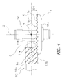
- FIG. 4 is a plan view of the rotor drive mechanism
- FIG. 5 is a flowchart representing a method of deriving a path of contact
- FIG. 6 is a chart representing an exemplary motion curve (relationship) in a shallow meshing state
- FIG. 7 is a chart representing an exemplary motion curve (relationship) in a deep meshing state
- FIG. 8 is a schematic diagram representing a contact path of a pinion gear on face gear tooth flanks
- FIG. 9 is a schematic diagram for explaining steps including a positioning step of the motion curves.
- FIG. 10 is a schematic diagram of face gear tooth flanks representing the path of contact
- FIG. 11 is a schematic diagram illustrating a three dimensional (3D) model of a face gear processed along the path of contact by cutting;
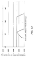
- FIG. 12 is a chart representing motion curves (relationships) of the 3D model illustrated in FIG. 11 in the deep meshing state;
- FIG. 13 is a schematic diagram representing the path of contact derived based on a direction of deriving a path of contact on the face gear tooth flanks;
- FIG. 14 is a schematic diagram representing a method of deriving the path of contact in the center of the tooth flanks
- FIG. 15 is a diagram for explaining three alignment errors and directions thereof.
- FIG. 16 is an allocation table representing an exemplary method of simulating production of rotational errors due to the alignment errors
- FIG. 17 is a comparative chart for the 3D model and the well-known product, representing simulation results of production of the rotational errors due to the alignment errors;
- FIG. 18 is a comparative chart for the 3D model and the well-kwon product, representing measurement results of production of rotational errors due to the alignment errors.
- FIG. 19 is a chart representing results of sensory evaluations for a spinning reel embedded with a prototype and that embedded with the well-known product.
- a spinning reel adopting an exemplary embodiment of the present invention includes a handle 1, a reel unit 2, a rotor 3, and a spool 4.
- the reel unit 2 supports the handle 1 while allowing the handle 1 to rotate.
- the rotor 3 is supported at the front of the reel unit 2.
- the spool 4 is configured to wind a fishing line onto the outer peripheral surface thereof.
- the spool 4 is disposed at the front of the rotor 3 while being movable back and forth. It should be noted that the handle 1 is attachable to either the right side or the left side of the reel unit 2.
- the handle 1 includes a handle shaft 1a, a handle arm 1b, and a handle knob 1c.
- the handle arm 1b extends from the handle shaft 1a in the radial direction of the handle shaft 1a.
- the handle knob 1c is rotatably attached to the extended end of the handle arm 1b.
- the reel unit 2 includes a reel body 2a and a lib member 2b (see FIG. 2 ).
- the reel body 2a includes a laterally opened accommodation space in the inside thereof.
- the lid member 2b is detachably attached to the reel body 2a for covering the opening of the accommodation space.
- the reel unit 2 includes a reel unit guard 26 for covering the rear part of the reel body 2a and that of the lid member 2b.
- the reel body 2a is made of light metal alloy such as magnesium alloy or aluminum alloy. Further, the reel body 2a includes a fishing rod attachment leg 2c integrally formed on the top thereof. The fishing rod attachment leg 2c is formed in a T-shape while the top thereof extends back and forth. Further, the reel body 2a accommodates a rotor drive mechanism 5 and an oscillation mechanism 6 in the accommodation space as illustrated in FIG. 1 .
- the rotor drive mechanism 5 (an example of a rotor drive device) is configured to rotate the rotor 3 in conjunction with rotation of the handle 1 for transmitting rotation of the handle 1 to the rotor 3.
- the rotor drive mechanism 5 includes a face gear 11 and a pinion gear 12.
- the face gear 11 is configured to rotate together with a face gear shaft 10 coupled to the handle shaft 1a of the handle 1 in a unitarily rotatable state.
- the pinion gear 12 meshes with the face gear 11.
- the face gear 11 is formed integrally with the face gear shaft 10 as illustrated in FIG. 2 .
- the face gear 11 can be alternatively formed separately from the face gear shaft 10.
- the face gear shaft 10 is screwed and coupled onto the handle shaft 1a in a unitarily rotatable state.
- the face gear shaft 10 can be alternatively coupled onto the handle shaft 1a in a unitarily rotatable state while a non-circular cross-sectional part of the face gear shaft 10 is engaged with that of the handle shaft 1a.
- the face gear shaft 10 is rotatably attached to the reel unit 2 through bearings 27a and 27b.
- the bearing 27a is attached to the lid member 2b, whereas the bearing 27b is attached to the reel body 2a.
- the face gear shaft 10 includes a left female threaded portion 10a and a right female threaded portion 10b on the inner peripheral surfaces of the both ends thereof. Either the left female threaded portion 10a or the right female threaded portion 10b is allowed to be screwed onto the handle shaft 1a.
- the left female threaded portion 10a which is disposed closer to the face gear 11, is a left-handed screw
- the right female threaded portion 10b disposed away from the face gear 11, is a right-handed screw.
- the handle shaft 1a is herein prepared to be used as either the right-handed screw or the left-handed screw.
- the face gear 11 includes a disc portion 11a and a face gear portion 11b.
- the disc portion 11a is integrally formed with the face gear shaft 10.
- the face gear portion 11b is formed on the outer radial part of one of the faces of the disc portion 11a.
- the face gear portion 11b includes a plurality of face gear teeth 11c circumferentially aligned at predetermined intervals on the outer radial part of the aforementioned face of the disc portion 11a.
- the face gear 11, together with the face gear shaft 10, is formed by forging of aluminum alloy for example.
- each of the face gear teeth 11c includes a first tooth flank 11d and a second tooth flank 11e.
- the first tooth flank 11d is configured to be meshed with the pinion gear 12 when the handle 1 is rotated in the fishing-line winding direction.
- the second tooth flank 11e is configured to be meshed with the pinion gear 12 when the handle 1 is rotated in the fishing-line releasing direction.
- At least the first tooth flank 11d is formed along a path of contact to be derived by a path-of-contact deriving method to be described. As illustrated in FIG.
- each first tooth flank 11d is formed as a coast (i.e., a concave surface) and a center part of the first tooth flank 11d in the tooth trace direction is recessed, whereas the second tooth flank 11e is formed as a drive (i.e., a convex surface) that its center part in the tooth trace direction protrudes.
- the pinion gear 12 includes a tubular gear body 12a and a gear portion 12b.
- the gear portion 12b includes helical teeth 12c formed on the outer peripheral surface of the rear part of the gear body 12a.
- the gear body 12a is attached to the reel body 2a while being rotatable about an axis (i.e., a spool shaft 15) arranged skew to the handle shaft 1a.
- the gear body 12a is rotatably supported by the reel body 2a through a front bearing 14a and a rear bearing 14b.
- the front bearing 14a is herein disposed forward of the gear portion 12b, whereas the rear bearing 14b is disposed rearward of the gear portion 12b.
- the gear body 12a includes a through hole 12d in the center thereof for allowing the spool shaft 15 to penetrate therethrough.
- the gear body 12a includes a male threaded portion 12e on the outer peripheral surface of the front end thereof.
- a nut 13 is screwed onto the male threaded portion 12e for fixing the rotor 3.
- the gear body 12a further includes a pair of anti-rotation planes 12f on the outer peripheral surface of the front part thereof.
- the anti-rotation planes 12f are parallel planes used for coupling the rotor 3 onto the pinion gear 12 in a unitarily rotatable state.
- the pinion gear 12 is designed to be meshed with the face gear 11 at a reference contact height SH (an example of a reference contact position of the pinion gear 12 with respect to the face gear 11). As illustrated in FIG. 15 , the pinion gear 12 is displaced from the rotational center Z of the face gear 11 by a reference offset amount OS.
- the pitch circle of the face gear 11 is arranged closer to the roots of the face gear teeth 11c from the tips of the face gear teeth 11c by the addendum of the pinion gear 12 (calculated by (outside diameter - pitch circle diameter)/2), i.e., the distance from the tops of the helical teeth 12c to the pitch circle diameter of the pinion gear 12.
- the pitch circle of the pinion gear 12 and the pitch circle of the face gear 11 are matched at the reference contact height SH.
- the reference offset amount OS is defined as the distance from the rotational center Z of the face gear 11 to the rotational center X of the pinion gear 12, as illustrated in FIG. 15 .
- the oscillation mechanism 6 is configured to move back and forth the spool shaft 15 coupled to the center part of the spool 4 through a drag mechanism 60 for moving the spool 4 in the same direction as the spool shaft 15.
- the oscillation mechanism 6 includes a traverse cam shaft 21, a slider 22 and an intermediate gear 23.
- the traverse cam shaft 21 is disposed below and in parallel to the spool shaft 15.
- the slider 22 is guided by the reel body 2a while being movable back and forth along the traverse cam shaft 21.
- the intermediate gear 23 is fixed to the tip of the traverse cam shaft 21.
- the rear end of the spool shaft 15 is fixed to the slider 22 while being prevented from rotating.
- the intermediate gear 23 is meshed with the pinion gear 12.
- the rotor 3 is made of light alloy such as magnesium alloy or aluminum alloy. As illustrated in FIG. 1 , the rotor 3 is coupled with the pinion gear 12 while being prevented from rotating. However, the rotor 3 is rotatable with respect to the reel unit 2.
- the rotor 3 includes a tubular portion 30, a first rotor arm 31, and a second rotor arm 32.
- the tubular portion 30 is coupled with the pinion gear 12 in a unitarily rotatable state.
- the first and second rotor arms 31 and 32 are connected to the rear part of the tubular portion 30 while being opposed to each other. Each of the first and second rotor arms 31 and 32 is forwardly extended at an interval from the tubular portion 30.
- the tubular portion 30 includes a disc-shaped wall portion 30d on the inner peripheral side of the front part thereof.
- the wall portion 30d includes an annular boss 30e in the center part thereof.
- the boss 30e is coupled to the pinion gear 12 in a unitarily rotatable state.
- the front part of the pinion gear 12 penetrates through the inner periphery of the boss 30e while the anti-rotation planes 12f formed on the front part of the pinion gear 12 are fitted onto the inner peripheral surface of the boss 30e in a unitarily rotatable state.
- the nut 13 is screwed onto the male threaded portion 12e of the pinion gear 12.
- the rotor 3 is thereby fixed to the pinion gear 12.
- a bail arm 44 is attached to the outer peripheral side of the tip of the first rotor arm 31 for guiding the fishing line to the spool 4 while being pivotable between a fishing-line releasing position and a fishing-line winding position.
- the rotor 3 accommodates an anti-rotation mechanism 50 in the inside of the tubular portion 30 thereof.
- the anti-rotation mechanism 50 is configured to prevent or allow reverse rotation of the rotor 3.
- the anti-reverse mechanism 50 includes a one-way clutch 51 and a switching lever 52.
- the one-way clutch 51 is a roller-type one-way clutch that an inner race is allowed to freely rotate.
- the switching lever 52 is configured to switch the one-way clutch 51 between an activated state (i.e., an anti-reverse rotational state) and a deactivated state (i.e., a reverse rotational state).
- the switching lever 52 is pivotably attached to the reel body 2a.
- a cam (not illustrated in the figures) is disposed on the tip of the switching lever 52. When the switching lever 52 is pivoted, the cam switches the one-way clutch 51 between the activated state and the deactivated state.
- the spool 4 is attached onto the tip of the spool shaft 15 through the drag mechanism 60 while being disposed between the first and second rotor arms 31 and 32 of the rotor 3.
- the spool 4 includes a bobbin trunk 4a, a skirt 4b, and a flange 4c.
- the bobbin trunk 4a is a portion for winding the fishing line about the outer periphery thereof.
- the skirt 4b is a tubular portion extended rearward from the bobbin trunk 4a.
- the skirt 4b is herein integrally formed with the bobbin trunk 4a.
- the flange 4c is a large diameter portion disposed on the front end of the bobbin trunk 4a.
- the drag mechanism 60 is configured to brake rotation of the spool 4.
- the drag mechanism 60 includes a drag regulation knob 61 and a brake portion 62.
- the drag regulation knob 61 is screwed onto the tip of the spool shaft 15.
- the brake portion 62 is configured to brake the spool 4 when being pressed by the drag regulation knob 61.
- the face gear 11 is configured to be rotated in conjunction with rotation of the handle 1 and the pinion gear 12 meshing with the face gear 11 is further rotated.
- the rotor 3 is thereby rotated in the fishing-line winding direction and the released fishing line is wound about the spool 4.
- the first tooth flanks 11d of the face gear teeth 11c of the face gear 11 are determined by a method of deriving a path of contact. Therefore, chances of unsmooth rotation of the handle 1 are reduced even when an error is produced in assembling the rotor drive mechanism 5.
- the method of deriving a path of contact on the face gear 11 includes a positioning step (Step S1), a curve creating step (Step S2), a curve positioning step (Step S3), a first coordinate calculating step (Step S4), a line calculating step (Step S5), a second coordinate calculating step (Step S6), an error calculating step (Step S7) and a determining step (Step S8).
- the respective steps are configured to be executed by a simulation processing using an electronic computer, such as a three-dimensional (3D) computer aided design (hereinafter simply referred to as CAD).
- CAD three-dimensional
- the specifications of the face gear 11 and the pinion gear 12 are set prior to execution of the method of deriving a path of contact on the face gear 11 by the simulation processing.
- the specification of the pinion gear 12 is set as follows: a module of 0.65 mm; a pressure angle of 20; a teeth number of 6; an addendum modification coefficient of + 0.5; and a torsion angle of 55 degrees.
- the specification of the face gear 11 is set as follows: a teeth number of 31; an outside diameter of 25.9 mm; an inside diameter of 21.4 mm; a reference offset (OS) of 6.5 mm; and a reference contact height (SH) of 3.725 mm.
- the pinion gear 12 is positioned to be in either a deep meshing state or a shallow meshing state in the positioning step (Step S1 in FIG. 5 ).
- the deep meshing state herein refers to a state that the pinion gear 12 is engaged with the face gear 11 at a position closer to the face gear 11 than the position at the reference contact height SH.
- the shallow meshing state refers to a state that the pinion gear 12 is engaged with the face gear 11 at a position away from the face gear 11 than the position at the reference contact height SH.
- a direction ⁇ H- indicates the direction for positioning the pinion gear 12 closer to the face gear 11 than the position at the reference contact height SH
- a direction ⁇ H+ indicates the direction for positioning the pinion gear 12 away from the face gear 11 than the position at the contact height SH.
- FIG. 4 illustrates a contact state between the pinion gear 12 and the face gear 11. It is empirically understood that gear noise largely varies when the pinion gear 12 is shifted along a third axis Z in FIG. 4 and non-uniform rotation is thereby caused.
- a motion curve (relationship) is created by the simulation based on the empirical rule as represented in FIGS. 6 and 7 .
- the motion curve is plotted on a chart where the vertical axis represents a rotational error (hereinafter referred to as "a transmission error") of the face gear 11 and the horizontal axis represents a rotation angle of the pinion gear 12.
- a transmission error a rotational error
- the motion curve indicates how rotation of the face gear 11 deviates from rotation of the pinion gear 12 when the pinion gear 12 is rotated at a constant speed by the amount of a single tooth of the face gear 11.
- the pinion gear 12 assumed in the CAD is rotated at a constant speed in the fishing-line winding direction, and the transmission error of the face gear 11 is calculated at intervals of a predetermined rotational angle of the pinion gear 12.
- the transmission error of the face gear 11 is herein set as a fluctuation error between the actual rotational angle of the face gear 11 and the rotational angle of the face gear 11 at a constant speed calculated based on a gear ratio.
- the motion curve is created by plotting thus calculated transmission error on a chart.
- FIG. 6 represents a motion curve (relationship) in the shallow meshing state
- FIG. 7 represents a motion curve (relationship) in the deep meshing state.
- the both charts indicate that the transmission error of the face gear 11 largely varies with respect to the rotational speed of the pinion gear 12 when the pinion gear 12 is shifted along the third axis Z.
- the motion curve is shaped as a flat-top trapezoid in the reference contact position SH.
- FIG. 8 is a chart obtained by matching the charts of the motion curves in FIGS. 6 and 7 and the contact positions.
- the pinion gear 12 is shifted from the reference contact height SH by + 0.05 mm along the third axis Z for producing the shallow meshing path, whereas the pinion gear 12 is shifted from the reference contact height SH by - 0.05 mm along the third axis Z for producing the deep meshing path.
- the motion curve depends on the tooth flank shape of the face gear teeth 11c of the face gear 11.
- the pinion gear 12 makes contact with the outer edges of the face gear teeth 11c of the face gear 11 in the deep meshing state
- the pinion gear 12 makes contact with the inner edge portions (including an interference preventing path) of the face gear teeth 11c of the face gear 11 in the shallow meshing state.
- the interference preventing path represented in FIG. 8 is a boundary between a contact tooth flank area and a tooth root interference area between the face gear teeth 11c and the pinion gear 12.
- two motion curves are additionally produced by horizontally shifting the aforementioned motion curve obtained by rotating the pinion gear 12 at a constant speed by the amount of a single tooth of the face gear 11. Accordingly, three motion curves are aligned. Specifically, the motion curve is shifted along the horizontal axis by a rotational angle obtained by dividing 360 by the number of teeth of the pinion gear 12 (e.g., 6). In the present exemplary embodiment, three motion curves (relationships) are thus aligned while being displaced at an angle of 60 degrees as represented in FIGS. 6 and 7 .
- the configuration shows the relation between the rotational angle of the pinion gear 12 and the transmission error of the face gear 11 with respect to three consecutive face gear teeth 11c of the face gear 11.
- Step S4 intersections among the three motion curves thus positioned are calculated from the 3D CAD data, for instance, in FIG. 9 that schematically represents the motion curves in the deep meshing state.
- the left, center and right motion curves are respectively referred to as a first tooth motion curve (an example of one of second motion curves), a second tooth motion curve (an example of a first motion curve) and a third tooth motion curve (an example of the other of the second motion curves).
- Step S4 a first intersection A between the first tooth motion curve and the second tooth motion curve and a second intersection C between the second tooth motion curve and the third tooth motion curve are calculated from the 3D CAD data.
- a first straight line L1 connecting the first intersection A and the second intersection C is calculated from the 3D data.
- a path of contact herein derived makes it possible to produce the tooth flanks for making the motion curve closer to the first straight line L1.
- the coordinate of a third intersection D is calculated from the 3D data.
- the third intersection D is an intersection between the first straight line L1 and a second straight line L2.
- the second straight line L2 is perpendicularly extended to the first straight line L1 from an error position B arranged between the first intersection A and the second intersection C on the second tooth motion curve. It should be noted that at least one error position B is herein set.
- the transmission error is calculated by subtracting a fluctuation error at the third intersection D from a fluctuation error at the error position B.
- the transmission error is, for instance, 0.0064 degrees.
- a dashed dotted curve represented in FIG. 10 is determined as a path of contact on the outer edge of the tooth flank 11d of each face gear tooth 11c of the face gear 11.
- the dashed dotted line connects at least three positions on the first tooth flank 11d of each face gear tooth 11c, and the three positions herein include a first contact position A1 of the pinion gear 12 in the first intersection A, a third contact position D 1 of the pinion gear 12 in the third intersection D when the face gear 11 is rotated by the amount of a transmission error, and a second contact position C1 of the pinion gear 12 in the second intersection C.
- the error position B and the third intersection D are herein arranged on the same contact line.
- the fluctuation error is set to be constant from the first intersection A to the second intersection C via the third intersection D on a single tooth. Non-uniform rotation is thereby prevented.
- the third intersection D is calculated between the first intersection A and the second intersection C for every predetermined rotational angle.
- a plurality of the third intersections D is herein calculated. Accordingly, a path of contact is determined at an arbitrary position. Further, the path of contact is determined on the outer peripheral side of the first tooth flank 11d as described above. However, the path of contact can be determined at any position on either the first tooth flank 11d or the second tooth flank 11e.
- FIG. 10 is a schematic diagram representing respective points on each first tooth flank 11d.
- the third intersection D represented in FIG. 9 is shifted from the outer end of each first tooth flank 11d to the inside of each first tooth flank 11d while being positioned substantially on the straight line connecting the first intersection A and the second intersection C.
- Another 3D model was herein created anew by cutting the aforementioned 3D model along the line connecting the first intersection A, the third intersection D and the second intersection C. Using the 3D model herein created, a simulation was executed regarding contact of the face gear 11 with the pinion gear 12. It should be noted that the simulation was executed only for each first tooth flank 11d functioning as a tooth flank in forward reel rotation.
- FIG. 10 is a schematic diagram representing respective points on each first tooth flank 11d.
- the third intersection D represented in FIG. 9 is shifted from the outer end of each first tooth flank 11d to the inside of each first tooth flank 11d while being positioned substantially on the straight line connecting the first intersection A and the second intersection C.
- Another 3D model was
- each face gear tooth 11c includes a facet 11f on its outer peripheral surface between the first tooth flank 11d and the second tooth flank 11e.
- the facet 11f is cut and formed by the path of contact derived by the aforementioned method.
- the facet 11f is shaped by obliquely short-cutting one of the top corners of each face gear tooth 11c.
- each first tooth flank 11d includes the aforementioned interference preventing path 11g on the inner edge portion thereof.
- FIG. 12 herein represents motion curves (relationships) derived by the CAD simulation where the pinion gear 12 is meshed with the face gear 11 of the aforementioned 3D model in the deep meshing state.
- the motion curves represented in FIG. 12 are flatter and less fluctuating than those represented in FIG. 7 . Thus, this indicates that non-uniform rotation is less caused by the face gear 11 including the facets 11f cut and formed along the path of contact.
- the path of contact is set on the outer peripheral side of each first tooth flank 11d as described above. However, the path of contact can be set on either the outer peripheral side or the inner peripheral side of either each first tooth flank 11d or each second tooth flank 11e.
- the path of contact is set for obliquely short-cutting a corner between the interference preventing path and the inner peripheral side of each tooth flank as represented in FIG. 13 .
- the first intersection A, the second intersection C and the third intersection D can be calculated in the deep meshing state by shifting the first straight line L1 on the motion curves in a direction of reducing a fluctuation error, as represented in FIG. 14 .
- the path of contact can be set on a position away from the outer edge towards the inner peripheral side on each first tooth flank 11d.
- FIG. 13 shows that the path of contact in the deep meshing state and in the shallow meshing state are matched when being respectively shifted and determined towards the center part on each tooth flank.
- Assembly errors of the rotor drive mechanism 5 were verified through a simulation using the face gear 11 of the aforementioned 3D model. Specifically, three assembly errors of a height error, an offset error and a tilt axis error were verified as illustrated in FIG. 15 . Further, assembly errors were verified by comparing two 3D models.
- One of the 3D models is a conventional face gear with a theoretical shape, which is constructed by a model generating simulation.
- the other of the 3D models is a face gear with modified tooth flanks illustrated in FIG. 13 .
- the path of contact is positioned in the center part on each tooth flank, and only the center part of each theoretical tooth flank is left while the both areas adjacent to the center part are prevented from making contact with the pinion gear. It should be noted that the simulation was conducted only for the first tooth flanks 11d functioning as the tooth flanks in the forward reel rotation.
- FIG. 15 illustrates definitions and directions of the assembly errors.
- Nine simulations were conducted for each error type using an orthogonal array that contains three factors and three levels.
- FIG. 16 represents a verification design of the orthogonal array
- FIG. 17 represents a simulation result. It was found that the assembly errors greatly affected the tooth flanks of the conventional product with a theoretical shape. In contrast, it was found that the assembly errors hardly affected the tooth flanks of the face gear 11 of the present exemplary embodiment based on the path of contact.
- the tooth flank was formed for each gear tooth of the face gear 11 based on the aforementioned simulation. Specifically, the center part of each tooth flank is formed in a theoretical shape by disposing thereon the path of contact determined by the method of deriving a path of contact according to the present invention, while the both sides adjacent to the center part of each tooth flank are formed to avoid contact with the pinion gear 12. It should be noted that the outer peripheral edge is also formed to avoid contact with the pinion gear 12. In contrast, a face gear having the tooth flanks of a theoretical shape was created as an exemplary conventional product.
- FIG. 18 is a factorial effect chart of the measurement result of the first tooth flanks 11d where the vertical axis represents a contact transmission error per pitch as average of all the hear teeth.
- FIG. 19 represents a result of a sensory evaluation test regarding rotational feeling of a spinning reel that the face gear 11 of an exemplary embodiment of the present invention was actually incorporated.
- the vertical axis represents an evaluation result of the sensory test where a larger value indicates a better rotational feeling.
- the horizontal axis in the chart of FIG. 19 represents a clearance in the axial direction of the handle (i.e., a clearance in a contact height direction).
- the sensory evaluation test was conducted where three levels of clearance were set at intervals of 0.06 mm. It was also found from the result of the sensory evaluation test that the rotational feeling less fluctuated (i.e., non-uniform rotation was less caused) in the prototype of the present exemplary embodiment based on the path of contact.
- the patch of contact on the face gear was derived and determined by the simulation using the CAD
- the first tooth flanks 11d of the face gear teeth 11c of the face gear 11 were created in the 3D simulation based on the determined path of contact and were further verified by the simulation. As a result, it was confirmed that the face gear 11 was less affected by three assembly errors of a contact height error, an offset error and a tilt axis error.
- the measurement result of the contact transmission error for the prototype face gear was similar to that for the face gear created in the simulation. Accordingly, an advantageous effect could be confirmed in the prototype face gear actually processed.
- the path of contact is disposed in the center part of each tooth flank.
- the path of contact can be disposed in any part of each tooth flank.
- the face gear for the spinning reel has been exemplified for explaining the present invention.
- the present invention is not limited to the face gear for the spinning reel.
- the present invention can be applied to the other gears excluding the face gears, such as the bevel gears, the hypoid gears, and the helical gears.
- the present invention can be applied to all the gears meeting the application condition that the tooth flanks thereof are theoretical ones configured to change the way of contact with the paired gear from a line contact to a spot contact due to alignment errors and so forth.
- each tooth flank In the aforementioned exemplary embodiment, the center part and the outer edge of each tooth flank are formed along the path of contact. However, each tooth flank can be entirely formed along the path of contact.
- the present exemplary embodiment is intended to be applied to the spinning reels. Only the first tooth flanks 11d are thereby formed based on the path of contact because they are configured to be meshed with the teeth of the paired gear and receive a load in the fishing-line winding direction of the handle. However, the second tooth flanks 11e can be formed based on the path of contact for the case that the both directional rotations (i.e., the fishing-line winding direction and the fishing-line releasing direction) are transmitted to the face gear while a load is applied thereto and the case that a load is applied to the face gear when the send tooth flanks 11e make contact with the teeth of the paired gear.
- the both directional rotations i.e., the fishing-line winding direction and the fishing-line releasing direction
Abstract
Description
- The present application claims priority to and benefit of JP Patent Application
JP2010-23667 filed on 21 October 2010 - The present invention is related to a method of deriving a path of contact on a face gear using a face gear having a plurality of gear teeth and a pinion gear meshing with the face gear, a method of manufacturing a face gear, a face gear and a spinning reel rotor drive device.
- The spinning reels are generally structured under the condition that a handle shaft and a rotor are respectively disposed about axes skew to each other. Therefore, a rotor drive mechanism includes a face gear and a pinion gear with helical gear teeth for transmitting rotation of a handle to the rotor. The face gear includes gear teeth formed by cutting a disc using a cutting tool that has the same shape as the pinion gear with the helical gear teeth. Accordingly, anglers feel that the handle is smoothly rotated (the angler's feeling with respect to the handle rotation will be hereinafter referred to as "rotational feeling").
- Japan Laid-open Patent Application Publication No.
JP-A-2010-075075 - As is the case with the face gear produced by die forming, the face gear is not uniformly rotated with respect to the pinion gear when the face gear and the pinion gear are even slightly misaligned from a reference contact position in assembling the rotor drive mechanism. Non-uniform rotation of the face gear results in unsmooth rotation of the handle and this can deteriorate rotational feeling. Therefore, it takes tremendous time for assembling and adjusting the rotor drive mechanism.
- The present invention addresses a need to produce a face gear prevented from non-uniformly rotating as much as possible even when an error is produced in its assembly dimension.
- A method of deriving a path of contact of a face gear including a plurality of gear teeth in meshing with a pinion gear is provided. The method includes positioning the pinion gear for meshing with the face gear at a prescribed reference contact position, shifting the pinion gear from the reference contact position either towards or away from the face gear along a rotational axis of the face gear, deriving a first relationship between a rotational angle of the pinion gear and a fluctuation error of a rotational angle of the face gear, deriving a second relationship between the rotational angle of the pinion gear and the fluctuation error by shifting the first relationship by subtracting from the rotational angle an angle of 360 degree divided by the number of the gear teeth, deriving a third relationship between the rotational angle of the pinion gear and the fluctuation error by shifting the first relationship by adding to the rotational angle the angle of 360 degree divided by the number of the gear teeth, deriving a first point which the first and second relationships share and a second point which the first and third relationships share wherein the first point has a first fluctuation error and the second point has the firs fluctuation error, deriving a third point, which has the fluctuation error, between the first and second points, and determining a curve line connecting a first contact position, a second contact position, and a third contact position as the path of contact on tooth flanks of the gear teeth of the face gear. The first contact position is set as a contact position of the pinion gear and corresponds to the first point. The second contact position is set as a contact position of the pinion gear and corresponds to the second point. The third contact position is set as a contact position of the pinion gear and corresponds to the third point when the face gear is rotated for an angle for the rotational error.
- In the method of deriving a path of contact on a face gear of the first aspect of the present invention, the motion curve for one of the gear teeth of the face gear is created by plotting the rotational error of the face gear with respect to the rotational angle of the pinion gear (also referred to as "a transmission error of the face gear") while the face gear and the pinion gear are meshed in a position displaced from the reference position. Then, totally three or more motion curves are disposed by shifting the created motion curve along the first axis at intervals of an angle of 360/N. The coordinates of the first and second intersections among the three or more motion curves are then calculated and the first straight line connecting the first and second intersections is calculated. Further, the coordinate(s) of the third intersection(s) is calculated as the intersection(s) between the first straight line and the second straight line(s) perpendicularly extended to the first straight line from at least an error position disposed between the first intersection and the second intersection. Next, the rotational error(s) is calculated by subtracting the fluctuation error(s) in the third step from the fluctuation error(s) of the error position(s). Then, the path of contact on the tooth flanks of the gear teeth of the face gear is determined as the curve connecting at least the first contact position of the pinion gear in the first intersection, the second contact position of the pinion gear in the second intersection, and the third contact position(s) of the pinion gear in the third step, is derived as
- According to the method of deriving a path of contact on a face gear of the first aspect of the present invention, the path of contact is herein derived by shifting the motion curve, which indicates a rotational error produced when the face gear and the pinion gear are displaced from the reference position, back and forth by a degree of 360/N and then further setting the rotational error along the first straight line connecting the first intersection and the second intersection. Therefore, non-uniform rotation is less caused (i.e., fluctuation in a rotational error is reduced) even if the face gear and the pinion gear are displaced from the reference position when being assembled. Consequently, it is possible to produce a face gear that non-uniform rotation is less caused even if an assembly dimensional error is produced.
- A method of deriving a path of contact on a face gear according to a second aspect of the present invention relates to the method of deriving a path of contact on a face gear according to the first aspect of the present invention. In the second coordinate calculating step, the coordinates of the third intersections are calculated based on the error positions set at intervals of a predetermined rotational angle of the pinion gear. In the error calculating step, the rotational errors are calculated by subtracting the fluctuation errors of the third intersections from the fluctuation errors of the respective error positions. In the determining step, a curve connecting the first contact position, the second contact position and the third contact positions is determined as the path of contact.
- According to the method of deriving a path of contact on a face gear of the second aspect of the present invention, the number of data is increased for the path of contact. Therefore, fluctuation in a rotational error is further reduced even when the face gear and the pinion gear are displaced from the reference position.
- A method of deriving a path of contact on a face gear according to a third aspect of the present invention relates to the method of deriving a path of contact on a face gear according to one of the first and second aspects of the present invention. In the method, the respective steps are executed by a simulation using an electronic calculator.
- According to the method of deriving a path of contact on a face gear of the third aspect of the present invention, more complex calculations can be accurately executed through the data input of a program because the respective steps are executed by the simulation of the electronic calculator.
- A method of manufacturing a face gear according to a fourth aspect of the present invention is configured to process the tooth flanks of the gear teeth of the face gear based on the path of contact derived by the method of deriving the path of contact on the face fear according to one of the first to third aspects of the present invention.
- According to the method of manufacturing a face gear of the fourth aspect of the present invention, it is possible to produce a face gear that non-uniform rotation is less caused regardless of fluctuation in an assembly error.
- A face gear according to a fifth aspect of the present invention is a face gear including the tooth flanks processed based on the path of contact by means of the method of manufacturing the face gear according to the fourth aspect of the present invention.
- According to the face gear of the fifth aspect of the present invention, it is possible to produce a face gear that a rotational error is less fluctuated regardless of occurrence of an assembly error.
- A spinning reel rotor drive device according to a sixth aspect of the present invention is a device configured to transmit rotation of a handle shaft rotatably supported by a reel unit of a spinning reel to a rotor. The spinning reel rotor drive device includes the face gear according to the fifth aspect of the present invention and a pinion gear. The face gear is disposed onto the handle shaft in a unitarily rotatable state. The pinion gear is meshed with the face gear. The pinion gear is disposed along a direction skew to the handle shaft. The pinion gear is rotatably supported by the reel unit.
- According to the spinning reel rotor drive device of the sixth aspect of the present invention, fluctuation in a rotational error can be inhibited even when the pinion gear and the face gear are assembled while being displaced from a reference position. Therefore, non-uniform rotation is less caused in the face gear even when an assembly error is fluctuated.
- Overall, according to the present invention, a path of contact is derived by shifting the motion curve, which indicates a rotational error produced when the face gear and the pinion gear are displaced from the reference position, back and forth by a degree of 360/N and then further setting the rotational error along the first straight line connecting the first intersection and the second intersection. Therefore, non-uniform rotation is less caused (i.e., fluctuation in a rotational error is reduced) even if the face gear and the pinion gear are displaced from the reference position when being assembled. Consequently, it is possible to produce a face gear that non-uniform rotation is less caused even if an assembly dimensional error is produced.
- Referring now to the attached drawings which form a part of this original disclosure:
-
FIG. 1 is a cross-sectional side view of a spinning reel adopting an exemplary embodiment of the present invention; -
FIG. 2 is a cross-sectional rear view of the spinning reel ofFIG. 1 sectioned along a line II-II; -
FIG. 3 is an exploded perspective view of a rotor drive mechanism; -
FIG. 4 is a plan view of the rotor drive mechanism; -
FIG. 5 is a flowchart representing a method of deriving a path of contact; -
FIG. 6 is a chart representing an exemplary motion curve (relationship) in a shallow meshing state; -
FIG. 7 is a chart representing an exemplary motion curve (relationship) in a deep meshing state; -
FIG. 8 is a schematic diagram representing a contact path of a pinion gear on face gear tooth flanks; -
FIG. 9 is a schematic diagram for explaining steps including a positioning step of the motion curves; -
FIG. 10 is a schematic diagram of face gear tooth flanks representing the path of contact; -
FIG. 11 is a schematic diagram illustrating a three dimensional (3D) model of a face gear processed along the path of contact by cutting; -
FIG. 12 is a chart representing motion curves (relationships) of the 3D model illustrated inFIG. 11 in the deep meshing state; -
FIG. 13 is a schematic diagram representing the path of contact derived based on a direction of deriving a path of contact on the face gear tooth flanks; -
FIG. 14 is a schematic diagram representing a method of deriving the path of contact in the center of the tooth flanks; -
FIG. 15 is a diagram for explaining three alignment errors and directions thereof; -
FIG. 16 is an allocation table representing an exemplary method of simulating production of rotational errors due to the alignment errors; -
FIG. 17 is a comparative chart for the 3D model and the well-known product, representing simulation results of production of the rotational errors due to the alignment errors; -
FIG. 18 is a comparative chart for the 3D model and the well-kwon product, representing measurement results of production of rotational errors due to the alignment errors; and -
FIG. 19 is a chart representing results of sensory evaluations for a spinning reel embedded with a prototype and that embedded with the well-known product. - As illustrated in
FIG. 1 , a spinning reel adopting an exemplary embodiment of the present invention includes ahandle 1, areel unit 2, arotor 3, and aspool 4. Thereel unit 2 supports thehandle 1 while allowing thehandle 1 to rotate. Therotor 3 is supported at the front of thereel unit 2. Thespool 4 is configured to wind a fishing line onto the outer peripheral surface thereof. Thespool 4 is disposed at the front of therotor 3 while being movable back and forth. It should be noted that thehandle 1 is attachable to either the right side or the left side of thereel unit 2. - As illustrated in
FIGS. 1 and2 , thehandle 1 includes ahandle shaft 1a, ahandle arm 1b, and ahandle knob 1c. Thehandle arm 1b extends from thehandle shaft 1a in the radial direction of thehandle shaft 1a. Thehandle knob 1c is rotatably attached to the extended end of thehandle arm 1b. - As illustrated in
FIGS. 1 and2 , thereel unit 2 includes areel body 2a and alib member 2b (seeFIG. 2 ). Thereel body 2a includes a laterally opened accommodation space in the inside thereof. Thelid member 2b is detachably attached to thereel body 2a for covering the opening of the accommodation space. Further, thereel unit 2 includes areel unit guard 26 for covering the rear part of thereel body 2a and that of thelid member 2b. - The
reel body 2a is made of light metal alloy such as magnesium alloy or aluminum alloy. Further, thereel body 2a includes a fishingrod attachment leg 2c integrally formed on the top thereof. The fishingrod attachment leg 2c is formed in a T-shape while the top thereof extends back and forth. Further, thereel body 2a accommodates arotor drive mechanism 5 and anoscillation mechanism 6 in the accommodation space as illustrated inFIG. 1 . - The rotor drive mechanism 5 (an example of a rotor drive device) is configured to rotate the
rotor 3 in conjunction with rotation of thehandle 1 for transmitting rotation of thehandle 1 to therotor 3. As illustrated inFIGS. 2 and3 , therotor drive mechanism 5 includes aface gear 11 and apinion gear 12. The face gear 11is configured to rotate together with aface gear shaft 10 coupled to thehandle shaft 1a of thehandle 1 in a unitarily rotatable state. Thepinion gear 12 meshes with theface gear 11. - In the present exemplary embodiment, the
face gear 11 is formed integrally with theface gear shaft 10 as illustrated inFIG. 2 . However, theface gear 11 can be alternatively formed separately from theface gear shaft 10. In the present exemplary embodiment, theface gear shaft 10 is screwed and coupled onto thehandle shaft 1a in a unitarily rotatable state. However, theface gear shaft 10 can be alternatively coupled onto thehandle shaft 1a in a unitarily rotatable state while a non-circular cross-sectional part of theface gear shaft 10 is engaged with that of thehandle shaft 1a. Theface gear shaft 10 is rotatably attached to thereel unit 2 throughbearings bearing 27a is attached to thelid member 2b, whereas thebearing 27b is attached to thereel body 2a. Theface gear shaft 10 includes a left female threaded portion 10a and a right female threadedportion 10b on the inner peripheral surfaces of the both ends thereof. Either the left female threaded portion 10a or the right female threadedportion 10b is allowed to be screwed onto thehandle shaft 1a. Specifically, the left female threaded portion 10a, which is disposed closer to theface gear 11, is a left-handed screw, whereas the right female threadedportion 10b, disposed away from theface gear 11, is a right-handed screw. In other words, thehandle shaft 1a is herein prepared to be used as either the right-handed screw or the left-handed screw. - As illustrated in
FIGS. 2 ,3 and4 , theface gear 11 includes adisc portion 11a and aface gear portion 11b. Thedisc portion 11a is integrally formed with theface gear shaft 10. Theface gear portion 11b is formed on the outer radial part of one of the faces of thedisc portion 11a. Theface gear portion 11b includes a plurality offace gear teeth 11c circumferentially aligned at predetermined intervals on the outer radial part of the aforementioned face of thedisc portion 11a. Theface gear 11, together with theface gear shaft 10, is formed by forging of aluminum alloy for example. As illustrated inFIG. 4 , each of theface gear teeth 11c includes afirst tooth flank 11d and asecond tooth flank 11e. Thefirst tooth flank 11d is configured to be meshed with thepinion gear 12 when thehandle 1 is rotated in the fishing-line winding direction. Thesecond tooth flank 11e is configured to be meshed with thepinion gear 12 when thehandle 1 is rotated in the fishing-line releasing direction. At least thefirst tooth flank 11d is formed along a path of contact to be derived by a path-of-contact deriving method to be described. As illustrated inFIG. 15 , eachfirst tooth flank 11d is formed as a coast (i.e., a concave surface) and a center part of thefirst tooth flank 11d in the tooth trace direction is recessed, whereas thesecond tooth flank 11e is formed as a drive (i.e., a convex surface) that its center part in the tooth trace direction protrudes. - The
pinion gear 12 includes atubular gear body 12a and agear portion 12b. Thegear portion 12b includeshelical teeth 12c formed on the outer peripheral surface of the rear part of thegear body 12a. Thegear body 12a is attached to thereel body 2a while being rotatable about an axis (i.e., a spool shaft 15) arranged skew to thehandle shaft 1a. Thegear body 12a is rotatably supported by thereel body 2a through afront bearing 14a and arear bearing 14b. Thefront bearing 14a is herein disposed forward of thegear portion 12b, whereas therear bearing 14b is disposed rearward of thegear portion 12b. Thegear body 12a includes a throughhole 12d in the center thereof for allowing thespool shaft 15 to penetrate therethrough. Thegear body 12a includes a male threadedportion 12e on the outer peripheral surface of the front end thereof. Anut 13 is screwed onto the male threadedportion 12e for fixing therotor 3. Thegear body 12a further includes a pair of anti-rotation planes 12f on the outer peripheral surface of the front part thereof. The anti-rotation planes 12f are parallel planes used for coupling therotor 3 onto thepinion gear 12 in a unitarily rotatable state. - The
pinion gear 12 is designed to be meshed with theface gear 11 at a reference contact height SH (an example of a reference contact position of thepinion gear 12 with respect to the face gear 11). As illustrated inFIG. 15 , thepinion gear 12 is displaced from the rotational center Z of theface gear 11 by a reference offset amount OS. The pitch circle of theface gear 11 is arranged closer to the roots of theface gear teeth 11c from the tips of theface gear teeth 11c by the addendum of the pinion gear 12 (calculated by (outside diameter - pitch circle diameter)/2), i.e., the distance from the tops of thehelical teeth 12c to the pitch circle diameter of thepinion gear 12. Therefore, the pitch circle of thepinion gear 12 and the pitch circle of theface gear 11 are matched at the reference contact height SH. The reference offset amount OS is defined as the distance from the rotational center Z of theface gear 11 to the rotational center X of thepinion gear 12, as illustrated inFIG. 15 . - As illustrated in
FIGS. 1 and2 , theoscillation mechanism 6 is configured to move back and forth thespool shaft 15 coupled to the center part of thespool 4 through adrag mechanism 60 for moving thespool 4 in the same direction as thespool shaft 15. Theoscillation mechanism 6 includes atraverse cam shaft 21, aslider 22 and anintermediate gear 23. Thetraverse cam shaft 21 is disposed below and in parallel to thespool shaft 15. Theslider 22 is guided by thereel body 2a while being movable back and forth along thetraverse cam shaft 21. Theintermediate gear 23 is fixed to the tip of thetraverse cam shaft 21. The rear end of thespool shaft 15 is fixed to theslider 22 while being prevented from rotating. Theintermediate gear 23 is meshed with thepinion gear 12. - The
rotor 3 is made of light alloy such as magnesium alloy or aluminum alloy. As illustrated inFIG. 1 , therotor 3 is coupled with thepinion gear 12 while being prevented from rotating. However, therotor 3 is rotatable with respect to thereel unit 2. Therotor 3 includes atubular portion 30, afirst rotor arm 31, and asecond rotor arm 32. Thetubular portion 30 is coupled with thepinion gear 12 in a unitarily rotatable state. The first andsecond rotor arms tubular portion 30 while being opposed to each other. Each of the first andsecond rotor arms tubular portion 30. - The
tubular portion 30 includes a disc-shapedwall portion 30d on the inner peripheral side of the front part thereof. Thewall portion 30d includes anannular boss 30e in the center part thereof. Theboss 30e is coupled to thepinion gear 12 in a unitarily rotatable state. The front part of thepinion gear 12 penetrates through the inner periphery of theboss 30e while the anti-rotation planes 12f formed on the front part of thepinion gear 12 are fitted onto the inner peripheral surface of theboss 30e in a unitarily rotatable state. Under the condition, thenut 13 is screwed onto the male threadedportion 12e of thepinion gear 12. Therotor 3 is thereby fixed to thepinion gear 12. Abail arm 44 is attached to the outer peripheral side of the tip of thefirst rotor arm 31 for guiding the fishing line to thespool 4 while being pivotable between a fishing-line releasing position and a fishing-line winding position. - The
rotor 3 accommodates ananti-rotation mechanism 50 in the inside of thetubular portion 30 thereof. Theanti-rotation mechanism 50 is configured to prevent or allow reverse rotation of therotor 3. Theanti-reverse mechanism 50 includes a one-way clutch 51 and a switchinglever 52. The one-way clutch 51 is a roller-type one-way clutch that an inner race is allowed to freely rotate. The switchinglever 52 is configured to switch the one-way clutch 51 between an activated state (i.e., an anti-reverse rotational state) and a deactivated state (i.e., a reverse rotational state). The switchinglever 52 is pivotably attached to thereel body 2a. A cam (not illustrated in the figures) is disposed on the tip of the switchinglever 52. When the switchinglever 52 is pivoted, the cam switches the one-way clutch 51 between the activated state and the deactivated state. - As illustrated in
FIG. 1 , thespool 4 is attached onto the tip of thespool shaft 15 through thedrag mechanism 60 while being disposed between the first andsecond rotor arms rotor 3. Thespool 4 includes abobbin trunk 4a, askirt 4b, and aflange 4c. Thebobbin trunk 4a is a portion for winding the fishing line about the outer periphery thereof. Theskirt 4b is a tubular portion extended rearward from thebobbin trunk 4a. Theskirt 4b is herein integrally formed with thebobbin trunk 4a. Theflange 4c is a large diameter portion disposed on the front end of thebobbin trunk 4a. - The
drag mechanism 60 is configured to brake rotation of thespool 4. Thedrag mechanism 60 includes adrag regulation knob 61 and abrake portion 62. Thedrag regulation knob 61 is screwed onto the tip of thespool shaft 15. Thebrake portion 62 is configured to brake thespool 4 when being pressed by thedrag regulation knob 61. - In the above structured spinning reel, when an angler rotates the
handle 1 in the fishing-line winding direction while thebail arm 44 is set to be in the fishing-line guiding position, theface gear 11 is configured to be rotated in conjunction with rotation of thehandle 1 and thepinion gear 12 meshing with theface gear 11 is further rotated. Therotor 3 is thereby rotated in the fishing-line winding direction and the released fishing line is wound about thespool 4. Thefirst tooth flanks 11d of theface gear teeth 11c of theface gear 11 are determined by a method of deriving a path of contact. Therefore, chances of unsmooth rotation of thehandle 1 are reduced even when an error is produced in assembling therotor drive mechanism 5. - The following explanation is related to steps in a method of deriving a path of contact on a face gear according to an exemplary embodiment of the present invention. The steps will be hereinafter explained with reference to a flowchart represented in
FIG. 5 . The method of deriving a path of contact on theface gear 11 includes a positioning step (Step S1), a curve creating step (Step S2), a curve positioning step (Step S3), a first coordinate calculating step (Step S4), a line calculating step (Step S5), a second coordinate calculating step (Step S6), an error calculating step (Step S7) and a determining step (Step S8). The respective steps are configured to be executed by a simulation processing using an electronic computer, such as a three-dimensional (3D) computer aided design (hereinafter simply referred to as CAD). - First, the specifications of the
face gear 11 and thepinion gear 12 are set prior to execution of the method of deriving a path of contact on theface gear 11 by the simulation processing. In the present exemplary embodiment, the specification of thepinion gear 12 is set as follows: a module of 0.65 mm; a pressure angle of 20; a teeth number of 6; an addendum modification coefficient of + 0.5; and a torsion angle of 55 degrees. - On the other hand, the specification of the
face gear 11 is set as follows: a teeth number of 31; an outside diameter of 25.9 mm; an inside diameter of 21.4 mm; a reference offset (OS) of 6.5 mm; and a reference contact height (SH) of 3.725 mm. - When the specification of the
face gear 11 is set, thepinion gear 12 is positioned to be in either a deep meshing state or a shallow meshing state in the positioning step (Step S1 inFIG. 5 ). The deep meshing state herein refers to a state that thepinion gear 12 is engaged with theface gear 11 at a position closer to theface gear 11 than the position at the reference contact height SH. In contrast, the shallow meshing state refers to a state that thepinion gear 12 is engaged with theface gear 11 at a position away from theface gear 11 than the position at the reference contact height SH. InFIG. 15 , a direction ΔH- indicates the direction for positioning thepinion gear 12 closer to theface gear 11 than the position at the reference contact height SH, whereas a direction ΔH+ indicates the direction for positioning thepinion gear 12 away from theface gear 11 than the position at the contact height SH. -
FIG. 4 illustrates a contact state between thepinion gear 12 and theface gear 11. It is empirically understood that gear noise largely varies when thepinion gear 12 is shifted along a third axis Z inFIG. 4 and non-uniform rotation is thereby caused. - In the curve creating step (Step S2), a motion curve (relationship) is created by the simulation based on the empirical rule as represented in
FIGS. 6 and7 . The motion curve is plotted on a chart where the vertical axis represents a rotational error (hereinafter referred to as "a transmission error") of theface gear 11 and the horizontal axis represents a rotation angle of thepinion gear 12. Specifically, the motion curve indicates how rotation of theface gear 11 deviates from rotation of thepinion gear 12 when thepinion gear 12 is rotated at a constant speed by the amount of a single tooth of theface gear 11. In the simulation, thepinion gear 12 assumed in the CAD is rotated at a constant speed in the fishing-line winding direction, and the transmission error of theface gear 11 is calculated at intervals of a predetermined rotational angle of thepinion gear 12. The transmission error of theface gear 11 is herein set as a fluctuation error between the actual rotational angle of theface gear 11 and the rotational angle of theface gear 11 at a constant speed calculated based on a gear ratio. Then, the motion curve is created by plotting thus calculated transmission error on a chart.FIG. 6 represents a motion curve (relationship) in the shallow meshing state, whereasFIG. 7 represents a motion curve (relationship) in the deep meshing state. The both charts indicate that the transmission error of theface gear 11 largely varies with respect to the rotational speed of thepinion gear 12 when thepinion gear 12 is shifted along the third axis Z. Normally, the motion curve is shaped as a flat-top trapezoid in the reference contact position SH. - A trajectory of contact points between the
pinion gear 12 and theface gear 11 when thepinion gear 12 is shifted by Δ+ along the third axis Z is herein referred to as a shallow meshing path. In contrast, a trajectory of contact points between thepinion gear 12 and theface gear 11 when thepinion gear 12 is shifted by Δ- along the third axis Z is herein referred to as a deep meshing path.FIG. 8 is a chart obtained by matching the charts of the motion curves inFIGS. 6 and7 and the contact positions. InFIG. 8 , thepinion gear 12 is shifted from the reference contact height SH by + 0.05 mm along the third axis Z for producing the shallow meshing path, whereas thepinion gear 12 is shifted from the reference contact height SH by - 0.05 mm along the third axis Z for producing the deep meshing path. Based on the correspondence, it can be predicted that the motion curve depends on the tooth flank shape of theface gear teeth 11c of theface gear 11. Simply put, it can be detected that thepinion gear 12 makes contact with the outer edges of theface gear teeth 11c of theface gear 11 in the deep meshing state, whereas thepinion gear 12 makes contact with the inner edge portions (including an interference preventing path) of theface gear teeth 11c of theface gear 11 in the shallow meshing state. It should be noted that the interference preventing path represented inFIG. 8 is a boundary between a contact tooth flank area and a tooth root interference area between theface gear teeth 11c and thepinion gear 12. - In the curve positioning step (Step S3), two motion curves (relationships) are additionally produced by horizontally shifting the aforementioned motion curve obtained by rotating the
pinion gear 12 at a constant speed by the amount of a single tooth of theface gear 11. Accordingly, three motion curves are aligned. Specifically, the motion curve is shifted along the horizontal axis by a rotational angle obtained by dividing 360 by the number of teeth of the pinion gear 12 (e.g., 6). In the present exemplary embodiment, three motion curves (relationships) are thus aligned while being displaced at an angle of 60 degrees as represented inFIGS. 6 and7 . The configuration shows the relation between the rotational angle of thepinion gear 12 and the transmission error of theface gear 11 with respect to three consecutiveface gear teeth 11c of theface gear 11. - In the first coordinate calculating step (Step S4), intersections among the three motion curves thus positioned are calculated from the 3D CAD data, for instance, in
FIG. 9 that schematically represents the motion curves in the deep meshing state. In the chart ofFIG. 9 , the left, center and right motion curves are respectively referred to as a first tooth motion curve (an example of one of second motion curves), a second tooth motion curve (an example of a first motion curve) and a third tooth motion curve (an example of the other of the second motion curves). In Step S4, a first intersection A between the first tooth motion curve and the second tooth motion curve and a second intersection C between the second tooth motion curve and the third tooth motion curve are calculated from the 3D CAD data. - In the straight line calculating step (Step S5), a first straight line L1 connecting the first intersection A and the second intersection C is calculated from the 3D data. A path of contact herein derived makes it possible to produce the tooth flanks for making the motion curve closer to the first straight line L1.
- In the second coordinate calculating step (Step S6), the coordinate of a third intersection D is calculated from the 3D data. The third intersection D is an intersection between the first straight line L1 and a second straight line L2. The second straight line L2 is perpendicularly extended to the first straight line L1 from an error position B arranged between the first intersection A and the second intersection C on the second tooth motion curve. It should be noted that at least one error position B is herein set.
- In the error calculating step (Step S7), the transmission error is calculated by subtracting a fluctuation error at the third intersection D from a fluctuation error at the error position B. In
FIG. 9 , the transmission error is, for instance, 0.0064 degrees. - In the determining step (Step S8), a dashed dotted curve represented in
FIG. 10 is determined as a path of contact on the outer edge of thetooth flank 11d of eachface gear tooth 11c of theface gear 11. As shown inFIG. 10 , the dashed dotted line connects at least three positions on thefirst tooth flank 11d of eachface gear tooth 11c, and the three positions herein include a first contact position A1 of thepinion gear 12 in the first intersection A, a thirdcontact position D 1 of thepinion gear 12 in the third intersection D when theface gear 11 is rotated by the amount of a transmission error, and a second contact position C1 of thepinion gear 12 in the second intersection C. The error position B and the third intersection D are herein arranged on the same contact line. When the position of the third intersection D on the tooth flank is obtained by rotating theface gear 11 by the amount of a transmission error while being arranged together with the error position B on the same contact line, the fluctuation error is set to be constant from the first intersection A to the second intersection C via the third intersection D on a single tooth. Non-uniform rotation is thereby prevented. - It should be noted that the third intersection D is calculated between the first intersection A and the second intersection C for every predetermined rotational angle. In other words, a plurality of the third intersections D is herein calculated. Accordingly, a path of contact is determined at an arbitrary position. Further, the path of contact is determined on the outer peripheral side of the
first tooth flank 11d as described above. However, the path of contact can be determined at any position on either thefirst tooth flank 11d or thesecond tooth flank 11e. -
FIG. 10 is a schematic diagram representing respective points on eachfirst tooth flank 11d. The third intersection D represented inFIG. 9 is shifted from the outer end of eachfirst tooth flank 11d to the inside of eachfirst tooth flank 11d while being positioned substantially on the straight line connecting the first intersection A and the second intersection C. Another 3D model was herein created anew by cutting the aforementioned 3D model along the line connecting the first intersection A, the third intersection D and the second intersection C. Using the 3D model herein created, a simulation was executed regarding contact of theface gear 11 with thepinion gear 12. It should be noted that the simulation was executed only for eachfirst tooth flank 11d functioning as a tooth flank in forward reel rotation.FIG. 11 illustrates theface gear teeth 11c of theface gear 11 in the 3D model used for the simulation. Eachface gear tooth 11c includes afacet 11f on its outer peripheral surface between thefirst tooth flank 11d and thesecond tooth flank 11e. Thefacet 11f is cut and formed by the path of contact derived by the aforementioned method. Thefacet 11f is shaped by obliquely short-cutting one of the top corners of eachface gear tooth 11c. Further, eachfirst tooth flank 11d includes the aforementioned interference preventing path 11g on the inner edge portion thereof. -
FIG. 12 herein represents motion curves (relationships) derived by the CAD simulation where thepinion gear 12 is meshed with theface gear 11 of the aforementioned 3D model in the deep meshing state. The motion curves represented inFIG. 12 are flatter and less fluctuating than those represented inFIG. 7 . Thus, this indicates that non-uniform rotation is less caused by theface gear 11 including thefacets 11f cut and formed along the path of contact. - The path of contact is set on the outer peripheral side of each
first tooth flank 11d as described above. However, the path of contact can be set on either the outer peripheral side or the inner peripheral side of either eachfirst tooth flank 11d or eachsecond tooth flank 11e. - When the aforementioned method is applied to the shallow meshing state represented in
FIG. 6 , the path of contact is set for obliquely short-cutting a corner between the interference preventing path and the inner peripheral side of each tooth flank as represented inFIG. 13 . - In setting the path of contact in a position away from the outer/inner peripheral part towards the center part on each tooth flank, the first intersection A, the second intersection C and the third intersection D can be calculated in the deep meshing state by shifting the first straight line L1 on the motion curves in a direction of reducing a fluctuation error, as represented in
FIG. 14 . When the first to third intersections above calculated are applied to the chart represented inFIG. 13 , the path of contact can be set on a position away from the outer edge towards the inner peripheral side on eachfirst tooth flank 11d.FIG. 13 shows that the path of contact in the deep meshing state and in the shallow meshing state are matched when being respectively shifted and determined towards the center part on each tooth flank. - Assembly errors of the
rotor drive mechanism 5 were verified through a simulation using theface gear 11 of the aforementioned 3D model. Specifically, three assembly errors of a height error, an offset error and a tilt axis error were verified as illustrated inFIG. 15 . Further, assembly errors were verified by comparing two 3D models. One of the 3D models is a conventional face gear with a theoretical shape, which is constructed by a model generating simulation. The other of the 3D models is a face gear with modified tooth flanks illustrated inFIG. 13 . Specifically in the face gear of the latter 3D model, the path of contact is positioned in the center part on each tooth flank, and only the center part of each theoretical tooth flank is left while the both areas adjacent to the center part are prevented from making contact with the pinion gear. It should be noted that the simulation was conducted only for the first tooth flanks 11d functioning as the tooth flanks in the forward reel rotation. -
FIG. 15 illustrates definitions and directions of the assembly errors. Nine simulations were conducted for each error type using an orthogonal array that contains three factors and three levels.FIG. 16 represents a verification design of the orthogonal array, whereasFIG. 17 represents a simulation result. It was found that the assembly errors greatly affected the tooth flanks of the conventional product with a theoretical shape. In contrast, it was found that the assembly errors hardly affected the tooth flanks of theface gear 11 of the present exemplary embodiment based on the path of contact. - The tooth flank was formed for each gear tooth of the
face gear 11 based on the aforementioned simulation. Specifically, the center part of each tooth flank is formed in a theoretical shape by disposing thereon the path of contact determined by the method of deriving a path of contact according to the present invention, while the both sides adjacent to the center part of each tooth flank are formed to avoid contact with thepinion gear 12. It should be noted that the outer peripheral edge is also formed to avoid contact with thepinion gear 12. In contrast, a face gear having the tooth flanks of a theoretical shape was created as an exemplary conventional product. - Using a 3D measuring instrument, accuracy was measured for both the
face gear 11 of the present invention and the face gear of an exemplary conventional product. As a result, it was confirmed that all the tooth flanks had sufficient accuracy. - A contact transmission error was measured for both of the above created face gears. The measuring instrument herein installed was an encoder configured to generate 1296000 pulses per revolution respectively for the driving side and the driven side. Under the condition, the advance/delay angles of two face gears were accurately measured by driving the pinion gear. Using a gear measuring instrument, accuracy was herein measured for the pinion gear for rotation. As a result of the measurement, it was confirmed that the pinion gear was finished in the
level 5 of the new JIS (Japanese Industrial Standards). Similarly to the aforementioned simulation, the measurement of the contact transmission error was conducted nine times using an orthogonal array that contains three factors and three levels.FIG. 18 is a factorial effect chart of the measurement result of thefirst tooth flanks 11d where the vertical axis represents a contact transmission error per pitch as average of all the hear teeth. - Comparison between
FIGS. 17 and18 shows that the both results have roughly the same tendency although difference is confirmed in absolute values. It is herein noteworthy that the prototype face gear of the exemplary embodiment of the present invention, having thefirst tooth flanks 11d formed based on the path of contact, was hardly affected by the assembly errors similarly to the 3D model of the aforementioned simulation. -
FIG. 19 represents a result of a sensory evaluation test regarding rotational feeling of a spinning reel that theface gear 11 of an exemplary embodiment of the present invention was actually incorporated. In the chart ofFIG. 19 , the vertical axis represents an evaluation result of the sensory test where a larger value indicates a better rotational feeling. On the other hand, the horizontal axis in the chart ofFIG. 19 represents a clearance in the axial direction of the handle (i.e., a clearance in a contact height direction). The sensory evaluation test was conducted where three levels of clearance were set at intervals of 0.06 mm. It was also found from the result of the sensory evaluation test that the rotational feeling less fluctuated (i.e., non-uniform rotation was less caused) in the prototype of the present exemplary embodiment based on the path of contact. - The patch of contact on the face gear was derived and determined by the simulation using the CAD
- The
first tooth flanks 11d of theface gear teeth 11c of theface gear 11 were created in the 3D simulation based on the determined path of contact and were further verified by the simulation. As a result, it was confirmed that theface gear 11 was less affected by three assembly errors of a contact height error, an offset error and a tilt axis error. - Evaluation was executed for the actually processed prototype face gear. The measurement result of the contact transmission error for the prototype face gear was similar to that for the face gear created in the simulation. Accordingly, an advantageous effect could be confirmed in the prototype face gear actually processed.
- Measurement and test were conducted for the prototype face gear actually incorporated in the spinning reel. As a result, it was confirmed that the prototype face gear, having the tooth flanks formed based on the path of contact, was less affected by three assembly errors of a contact height error, an offset error and a tilt axis error similarly to the product created in the simulation. Accordingly, it was verified that non-uniform rotation due to the assembly errors could be eliminated and assembly could be easily performed in mass production.
- An exemplary embodiment of the present invention has been described above. However, the present invention is not necessarily limited to the aforementioned exemplary embodiment and a variety of changes can be herein made without departing from the scope of the present invention.
- (a) In the aforementioned exemplary embodiment, the path of contact is disposed in the center part of each tooth flank. However, the path of contact can be disposed in any part of each tooth flank.
- (b) In the aforementioned exemplary embodiment, the face gear for the spinning reel has been exemplified for explaining the present invention. However, the present invention is not limited to the face gear for the spinning reel. For example, the present invention can be applied to the other gears excluding the face gears, such as the bevel gears, the hypoid gears, and the helical gears. The present invention can be applied to all the gears meeting the application condition that the tooth flanks thereof are theoretical ones configured to change the way of contact with the paired gear from a line contact to a spot contact due to alignment errors and so forth.
- (c) In the aforementioned exemplary embodiment, the center part and the outer edge of each tooth flank are formed along the path of contact. However, each tooth flank can be entirely formed along the path of contact.
- (d) The present exemplary embodiment is intended to be applied to the spinning reels. Only the
first tooth flanks 11d are thereby formed based on the path of contact because they are configured to be meshed with the teeth of the paired gear and receive a load in the fishing-line winding direction of the handle. However, thesecond tooth flanks 11e can be formed based on the path of contact for the case that the both directional rotations (i.e., the fishing-line winding direction and the fishing-line releasing direction) are transmitted to the face gear while a load is applied thereto and the case that a load is applied to the face gear when thesend tooth flanks 11e make contact with the teeth of the paired gear.
Claims (6)
- A method of deriving a path of contact of a face gear including a plurality of gear teeth in meshing with a pinion gear, the method comprising:positioning the pinion gear for meshing with the face gear at a prescribed reference contact position;shifting the pinion gear from the reference contact position either towards or away from the face gear along a rotational axis of the face gear;deriving a first relationship between a rotational angle of the pinion gear and a fluctuation error of a rotational angle of the face gear;deriving a second relationship between the rotational angle of the pinion gear and the fluctuation error by shifting the first relationship by subtracting from the rotational angle an angle of 360 degree divided by the number of the gear teeth;deriving a third relationship between the rotational angle of the pinion gear and the fluctuation error by shifting the first relationship by adding to the rotational angle the angle of 360 degree divided by the number of the gear teeth;deriving a first point which the first and second relationships share and a second point which the first and third relationships share, the first point having a first fluctuation error, the second point having the first fluctuation error;deriving a third point, which has the first fluctuation error, between the first and second points; anddetermining a curve line connecting a first contact position, a second contact position, and a third contact position as the path of contact on tooth flanks of the gear teeth of the face gear,the first contact position being set as a contact position of the pinion gear and corresponding to the first point,the second contact position being set as a contact position of the pinion gear and corresponding to the second point,the third contact position being set as a contact position of the pinion gear and corresponding to the third point when the face gear is rotated for an angle for the rotational error.
- The method of deriving the path of contact on the face gear according to claim 1, further comprising
deriving a fourth point which has the first fluctuation error between the first and second points;
calculating a rotational error for the fourth point by subtracting the fluctuation error of the third point from a fluctuation error of the fourth point; and
determining the curve line connecting the first contact position, the second contact position, the third contact position, and a fourth contact position as the path of contact, the fourth contact position being set as a contact position of the pinion gear in the fourth point when the face gear is rotated for the angle for the rotational error for the fourth point. - The method of deriving the path of contact according to claim 1 or 2, wherein
the method of deriving the curve path of contact is executed by a simulation by using an electronic computer. - A method of manufacturing a face gear by processing the tooth flanks based on the path of contact as derived according to claim 1, 2 or 3.
- A face gear including the tooth flanks processed according to claim 4 and/ or based on the path of contact as derived according to claim 1, 2 or 3.
- A spinning reel rotor drive device configured to transmit rotation of a handle shaft rotatably supported by a reel unit of a spinning reel to a rotor, comprising:the face gear according to claim 5 disposed onto the handle shaft in a unitarily rotatable state; anda pinion gear meshed with the face gear, the pinion gear disposed along a direction skew to the handle shaft, the pinion gear rotatably supported by the reel unit.
Applications Claiming Priority (1)
| Application Number | Priority Date | Filing Date | Title |
|---|---|---|---|
| JP2010236667A JP5501190B2 (en) | 2010-10-21 | 2010-10-21 | Method for determining meshing direction line of face gear, method for manufacturing face gear, rotor driving device for face gear and spinning reel |
Publications (3)
| Publication Number | Publication Date |
|---|---|
| EP2443921A2 true EP2443921A2 (en) | 2012-04-25 |
| EP2443921A3 EP2443921A3 (en) | 2012-11-14 |
| EP2443921B1 EP2443921B1 (en) | 2016-05-04 |
Family
ID=45044324
Family Applications (1)
| Application Number | Title | Priority Date | Filing Date |
|---|---|---|---|
| EP11186090.4A Active EP2443921B1 (en) | 2010-10-21 | 2011-10-21 | Method of manufacturing a face gear, face gear and spinning reel rotor drive device |
Country Status (3)
| Country | Link |
|---|---|
| US (1) | US8888031B2 (en) |
| EP (1) | EP2443921B1 (en) |
| JP (1) | JP5501190B2 (en) |
Cited By (5)
| Publication number | Priority date | Publication date | Assignee | Title |
|---|---|---|---|---|
| CN102661381A (en) * | 2012-05-27 | 2012-09-12 | 西北工业大学 | Four-stage transmission error curve of spiral bevel gear and design method thereof |
| CN103343807A (en) * | 2013-07-17 | 2013-10-09 | 北京工业大学 | Cycloid curve bevel gear edge contact analysis method |
| CN111637144A (en) * | 2020-05-30 | 2020-09-08 | 上海建桥学院 | Gear shaft part and machining method thereof |
| US20210317904A1 (en) * | 2020-04-14 | 2021-10-14 | Shimano Inc. | Drive gear for fishing reel |
| US11971093B2 (en) | 2020-04-14 | 2024-04-30 | Shimano Inc. | Drive gear for fishing reel |
Families Citing this family (12)
| Publication number | Priority date | Publication date | Assignee | Title |
|---|---|---|---|---|
| JP5501190B2 (en) * | 2010-10-21 | 2014-05-21 | 株式会社シマノ | Method for determining meshing direction line of face gear, method for manufacturing face gear, rotor driving device for face gear and spinning reel |
| WO2013109305A1 (en) | 2011-08-19 | 2013-07-25 | Aerovironment, Inc. | Water-tight compartment with removable hatch and two-sided gel seal for multiple conduit access |
| EP2749164A4 (en) * | 2012-05-29 | 2016-02-24 | Globeride Inc | Spinning fishing reel |
| JP2014010133A (en) * | 2012-07-03 | 2014-01-20 | Aisin Seiki Co Ltd | Inspection fixture for face gear |
| JP5995321B2 (en) * | 2013-02-28 | 2016-09-21 | グローブライド株式会社 | Fishing spinning reel |
| JP6219702B2 (en) * | 2013-12-16 | 2017-10-25 | 株式会社シマノ | Fishing reel drive gear and fishing reel pinion gear |
| US9226485B2 (en) * | 2013-12-23 | 2016-01-05 | Heligear Engineering (H.K.) Co. Ltd | Fishing reel and drive mechanism therefor |
| US9812923B2 (en) * | 2014-05-23 | 2017-11-07 | Aero Industries, Inc. | Gear motor |
| US10004214B2 (en) * | 2014-10-17 | 2018-06-26 | Haibao Fishing Tackle Co., Ltd. | Spinning reel with variable gear ratio transmission |
| JP6419020B2 (en) * | 2015-04-28 | 2018-11-07 | グローブライド株式会社 | Fishing spinning reel |
| JP7049776B2 (en) | 2017-04-26 | 2022-04-07 | 株式会社シマノ | Gear mechanism of fishing reel |
| US11543012B2 (en) * | 2020-07-20 | 2023-01-03 | Endurance Innovations, LLC | Gear unit |
Citations (2)
| Publication number | Priority date | Publication date | Assignee | Title |
|---|---|---|---|---|
| JP2010023667A (en) | 2008-07-18 | 2010-02-04 | Asmo Co Ltd | Wiper arm and wiper for vehicle |
| JP2010075075A (en) | 2008-09-25 | 2010-04-08 | Shimano Inc | Master gear of spinning reel, and rotation-transmitting mechanism |
Family Cites Families (15)
| Publication number | Priority date | Publication date | Assignee | Title |
|---|---|---|---|---|
| US2409999A (en) * | 1935-03-29 | 1946-10-29 | Miller Pottery Engineering Co | Apparatus for producing pottery ware |
| US2274761A (en) * | 1937-04-17 | 1942-03-03 | Gleason Works | Gear cutter and method of cutting gears |
| US2969177A (en) * | 1950-11-06 | 1961-01-24 | Realty Ind Corp | Partial product calculating machine |
| US3591109A (en) * | 1966-06-29 | 1971-07-06 | Frank W Mclarty | Rotary wing aircraft |
| US5116173A (en) * | 1991-02-26 | 1992-05-26 | The Gleason Works | Method of generating bevel and hypoid gears |
| US5570633A (en) * | 1993-06-01 | 1996-11-05 | Comco Machinery, Inc. | Automated printing press with reinsertion registration control |
| NL9401735A (en) * | 1994-10-19 | 1996-06-03 | Crown Gear Bv | Gear transmission of a cylindrical pinion with a crown wheel, the crown wheel used in this gear transmission, a method according to which the crown wheel can be made and a tool with which the crown wheel can be made. |
| JP3358494B2 (en) | 1997-05-20 | 2002-12-16 | トヨタ自動車株式会社 | Gears and gear tooth surface modification method |
| JP2000166437A (en) * | 1998-12-02 | 2000-06-20 | Shimano Inc | Rotation transmission mechanism of reel for fishing |
| WO2000054569A1 (en) * | 1999-03-16 | 2000-09-21 | Kverneland Kerteminde A/S | Gear box housing |
| NL1020562C2 (en) * | 2002-05-08 | 2003-11-11 | Norma B V | Crown wheel. |
| JP2007259713A (en) * | 2006-03-27 | 2007-10-11 | Daiwa Seiko Inc | Fishing spinning reel |
| JP2008095774A (en) * | 2006-10-10 | 2008-04-24 | Gkn ドライブライン トルクテクノロジー株式会社 | Face gear transmission mechanism and differential device using the same |
| CN102224360B (en) * | 2008-11-25 | 2014-04-02 | 格里森工场 | Hypoid gears with low shaft angles |
| JP5501190B2 (en) * | 2010-10-21 | 2014-05-21 | 株式会社シマノ | Method for determining meshing direction line of face gear, method for manufacturing face gear, rotor driving device for face gear and spinning reel |
-
2010
- 2010-10-21 JP JP2010236667A patent/JP5501190B2/en active Active
-
2011
- 2011-10-12 US US13/271,906 patent/US8888031B2/en active Active
- 2011-10-21 EP EP11186090.4A patent/EP2443921B1/en active Active
Patent Citations (2)
| Publication number | Priority date | Publication date | Assignee | Title |
|---|---|---|---|---|
| JP2010023667A (en) | 2008-07-18 | 2010-02-04 | Asmo Co Ltd | Wiper arm and wiper for vehicle |
| JP2010075075A (en) | 2008-09-25 | 2010-04-08 | Shimano Inc | Master gear of spinning reel, and rotation-transmitting mechanism |
Cited By (9)
| Publication number | Priority date | Publication date | Assignee | Title |
|---|---|---|---|---|
| CN102661381A (en) * | 2012-05-27 | 2012-09-12 | 西北工业大学 | Four-stage transmission error curve of spiral bevel gear and design method thereof |
| CN102661381B (en) * | 2012-05-27 | 2014-09-03 | 西北工业大学 | Four-stage transmission error curve of spiral bevel gear and design method thereof |
| CN103343807A (en) * | 2013-07-17 | 2013-10-09 | 北京工业大学 | Cycloid curve bevel gear edge contact analysis method |
| US20210317904A1 (en) * | 2020-04-14 | 2021-10-14 | Shimano Inc. | Drive gear for fishing reel |
| GB2595953A (en) * | 2020-04-14 | 2021-12-15 | Shimano Kk | Drive gear for a fishing reel |
| US11971093B2 (en) | 2020-04-14 | 2024-04-30 | Shimano Inc. | Drive gear for fishing reel |
| DE102021202327B4 (en) | 2020-04-14 | 2024-05-02 | Shimano Inc. | DRIVE GEAR FOR FISHING REEL |
| CN111637144A (en) * | 2020-05-30 | 2020-09-08 | 上海建桥学院 | Gear shaft part and machining method thereof |
| CN111637144B (en) * | 2020-05-30 | 2024-02-27 | 上海建桥学院 | Gear shaft part and processing method thereof |
Also Published As
| Publication number | Publication date |
|---|---|
| EP2443921B1 (en) | 2016-05-04 |
| US8888031B2 (en) | 2014-11-18 |
| JP2012087905A (en) | 2012-05-10 |
| US20120097779A1 (en) | 2012-04-26 |
| JP5501190B2 (en) | 2014-05-21 |
| EP2443921A3 (en) | 2012-11-14 |
Similar Documents
| Publication | Publication Date | Title |
|---|---|---|
| EP2443921B1 (en) | Method of manufacturing a face gear, face gear and spinning reel rotor drive device | |
| JP2012087905A5 (en) | ||
| US9539660B2 (en) | Tool for cutting gear and method for cutting gear | |
| US20140090503A1 (en) | Gear and manufacturing method for the same | |
| US8113750B2 (en) | Face hob hypoid gear tooth cutting by common blades | |
| EP2347649B1 (en) | Spinning reel spool support structure | |
| KR20130050880A (en) | Fishing-reel reel unit and fishing reel | |
| JP6444140B2 (en) | Rack bushing and steering device | |
| JP2016088339A (en) | Steering device | |
| CN108885083A (en) | Measurement to worm gear | |
| JP5276358B2 (en) | Hypoid gear analysis system | |
| JP4763611B2 (en) | Evaluation method of edge profile of re-sharpened pinion cutter | |
| JP2007185760A (en) | Setting device for hypoid gear machining machine | |
| TWI825767B (en) | Gear skiving cutter and designing method thereof | |
| US2935888A (en) | Enveloping worm gearing | |
| CN103116261B (en) | The draw bail of wrist-watch arbor and transmission wheel | |
| CN110110420B (en) | Modeling method, device and equipment for machining tooth surface of cambered surface worm | |
| CN109877406B (en) | Method for determining numerical control linear cutting taper machining error of cylindrical helical gear mold cavity | |
| US20190217406A1 (en) | Gear machining apparatus and gear machining method | |
| KR101444124B1 (en) | highly qualified worm gear and the production method thereof | |
| JP6566245B2 (en) | Worm reducer and steering device | |
| EP4012220A1 (en) | Harmonic gearing comprising three-dimensional tooth form | |
| Baroiu et al. | Hob mill for trilobed rotor–Graphical method in CATIA | |
| EP4012221A1 (en) | Wave gear device provided with three-dimensional tooth profile | |
| Goanta et al. | New Siemens applications for designing bevel gears |
Legal Events
| Date | Code | Title | Description |
|---|---|---|---|
| AK | Designated contracting states |
Kind code of ref document: A2 Designated state(s): AL AT BE BG CH CY CZ DE DK EE ES FI FR GB GR HR HU IE IS IT LI LT LU LV MC MK MT NL NO PL PT RO RS SE SI SK SM TR |
|
| AX | Request for extension of the european patent |
Extension state: BA ME |
|
| PUAI | Public reference made under article 153(3) epc to a published international application that has entered the european phase |
Free format text: ORIGINAL CODE: 0009012 |
|
| PUAL | Search report despatched |
Free format text: ORIGINAL CODE: 0009013 |
|
| AK | Designated contracting states |
Kind code of ref document: A3 Designated state(s): AL AT BE BG CH CY CZ DE DK EE ES FI FR GB GR HR HU IE IS IT LI LT LU LV MC MK MT NL NO PL PT RO RS SE SI SK SM TR |
|
| AX | Request for extension of the european patent |
Extension state: BA ME |
|
| RIC1 | Information provided on ipc code assigned before grant |
Ipc: F16H 55/08 20060101AFI20121010BHEP Ipc: A01K 89/01 20060101ALI20121010BHEP |
|
| 17P | Request for examination filed |
Effective date: 20130514 |
|
| REG | Reference to a national code |
Ref country code: DE Ref legal event code: R079 Ref document number: 602011026116 Country of ref document: DE Free format text: PREVIOUS MAIN CLASS: A01K0089010000 Ipc: F16H0055170000 |
|
| GRAP | Despatch of communication of intention to grant a patent |
Free format text: ORIGINAL CODE: EPIDOSNIGR1 |
|
| RIC1 | Information provided on ipc code assigned before grant |
Ipc: F16H 55/17 20060101AFI20151016BHEP Ipc: A01K 89/01 20060101ALI20151016BHEP |
|
| INTG | Intention to grant announced |
Effective date: 20151117 |
|
| GRAS | Grant fee paid |
Free format text: ORIGINAL CODE: EPIDOSNIGR3 |
|
| GRAA | (expected) grant |
Free format text: ORIGINAL CODE: 0009210 |
|
| AK | Designated contracting states |
Kind code of ref document: B1 Designated state(s): AL AT BE BG CH CY CZ DE DK EE ES FI FR GB GR HR HU IE IS IT LI LT LU LV MC MK MT NL NO PL PT RO RS SE SI SK SM TR |
|
| REG | Reference to a national code |
Ref country code: GB Ref legal event code: FG4D |
|
| REG | Reference to a national code |
Ref country code: CH Ref legal event code: EP |
|
| REG | Reference to a national code |
Ref country code: AT Ref legal event code: REF Ref document number: 797205 Country of ref document: AT Kind code of ref document: T Effective date: 20160515 |
|
| REG | Reference to a national code |
Ref country code: IE Ref legal event code: FG4D |
|
| REG | Reference to a national code |
Ref country code: DE Ref legal event code: R096 Ref document number: 602011026116 Country of ref document: DE |
|
| REG | Reference to a national code |
Ref country code: NL Ref legal event code: MP Effective date: 20160504 |
|
| REG | Reference to a national code |
Ref country code: LT Ref legal event code: MG4D |
|
| REG | Reference to a national code |
Ref country code: FR Ref legal event code: PLFP Year of fee payment: 6 |
|
| PG25 | Lapsed in a contracting state [announced via postgrant information from national office to epo] |
Ref country code: FI Free format text: LAPSE BECAUSE OF FAILURE TO SUBMIT A TRANSLATION OF THE DESCRIPTION OR TO PAY THE FEE WITHIN THE PRESCRIBED TIME-LIMIT Effective date: 20160504 Ref country code: LT Free format text: LAPSE BECAUSE OF FAILURE TO SUBMIT A TRANSLATION OF THE DESCRIPTION OR TO PAY THE FEE WITHIN THE PRESCRIBED TIME-LIMIT Effective date: 20160504 Ref country code: NL Free format text: LAPSE BECAUSE OF FAILURE TO SUBMIT A TRANSLATION OF THE DESCRIPTION OR TO PAY THE FEE WITHIN THE PRESCRIBED TIME-LIMIT Effective date: 20160504 Ref country code: NO Free format text: LAPSE BECAUSE OF FAILURE TO SUBMIT A TRANSLATION OF THE DESCRIPTION OR TO PAY THE FEE WITHIN THE PRESCRIBED TIME-LIMIT Effective date: 20160804 |
|
| REG | Reference to a national code |
Ref country code: AT Ref legal event code: MK05 Ref document number: 797205 Country of ref document: AT Kind code of ref document: T Effective date: 20160504 |
|
| PG25 | Lapsed in a contracting state [announced via postgrant information from national office to epo] |
Ref country code: SE Free format text: LAPSE BECAUSE OF FAILURE TO SUBMIT A TRANSLATION OF THE DESCRIPTION OR TO PAY THE FEE WITHIN THE PRESCRIBED TIME-LIMIT Effective date: 20160504 Ref country code: HR Free format text: LAPSE BECAUSE OF FAILURE TO SUBMIT A TRANSLATION OF THE DESCRIPTION OR TO PAY THE FEE WITHIN THE PRESCRIBED TIME-LIMIT Effective date: 20160504 Ref country code: ES Free format text: LAPSE BECAUSE OF FAILURE TO SUBMIT A TRANSLATION OF THE DESCRIPTION OR TO PAY THE FEE WITHIN THE PRESCRIBED TIME-LIMIT Effective date: 20160504 Ref country code: PT Free format text: LAPSE BECAUSE OF FAILURE TO SUBMIT A TRANSLATION OF THE DESCRIPTION OR TO PAY THE FEE WITHIN THE PRESCRIBED TIME-LIMIT Effective date: 20160905 Ref country code: LV Free format text: LAPSE BECAUSE OF FAILURE TO SUBMIT A TRANSLATION OF THE DESCRIPTION OR TO PAY THE FEE WITHIN THE PRESCRIBED TIME-LIMIT Effective date: 20160504 Ref country code: RS Free format text: LAPSE BECAUSE OF FAILURE TO SUBMIT A TRANSLATION OF THE DESCRIPTION OR TO PAY THE FEE WITHIN THE PRESCRIBED TIME-LIMIT Effective date: 20160504 Ref country code: GR Free format text: LAPSE BECAUSE OF FAILURE TO SUBMIT A TRANSLATION OF THE DESCRIPTION OR TO PAY THE FEE WITHIN THE PRESCRIBED TIME-LIMIT Effective date: 20160805 |
|
| PG25 | Lapsed in a contracting state [announced via postgrant information from national office to epo] |
Ref country code: IT Free format text: LAPSE BECAUSE OF FAILURE TO SUBMIT A TRANSLATION OF THE DESCRIPTION OR TO PAY THE FEE WITHIN THE PRESCRIBED TIME-LIMIT Effective date: 20160504 |
|
| PG25 | Lapsed in a contracting state [announced via postgrant information from national office to epo] |
Ref country code: DK Free format text: LAPSE BECAUSE OF FAILURE TO SUBMIT A TRANSLATION OF THE DESCRIPTION OR TO PAY THE FEE WITHIN THE PRESCRIBED TIME-LIMIT Effective date: 20160504 Ref country code: CZ Free format text: LAPSE BECAUSE OF FAILURE TO SUBMIT A TRANSLATION OF THE DESCRIPTION OR TO PAY THE FEE WITHIN THE PRESCRIBED TIME-LIMIT Effective date: 20160504 Ref country code: EE Free format text: LAPSE BECAUSE OF FAILURE TO SUBMIT A TRANSLATION OF THE DESCRIPTION OR TO PAY THE FEE WITHIN THE PRESCRIBED TIME-LIMIT Effective date: 20160504 Ref country code: SK Free format text: LAPSE BECAUSE OF FAILURE TO SUBMIT A TRANSLATION OF THE DESCRIPTION OR TO PAY THE FEE WITHIN THE PRESCRIBED TIME-LIMIT Effective date: 20160504 Ref country code: RO Free format text: LAPSE BECAUSE OF FAILURE TO SUBMIT A TRANSLATION OF THE DESCRIPTION OR TO PAY THE FEE WITHIN THE PRESCRIBED TIME-LIMIT Effective date: 20160504 |
|
| REG | Reference to a national code |
Ref country code: DE Ref legal event code: R097 Ref document number: 602011026116 Country of ref document: DE |
|
| PG25 | Lapsed in a contracting state [announced via postgrant information from national office to epo] |
Ref country code: PL Free format text: LAPSE BECAUSE OF FAILURE TO SUBMIT A TRANSLATION OF THE DESCRIPTION OR TO PAY THE FEE WITHIN THE PRESCRIBED TIME-LIMIT Effective date: 20160504 Ref country code: BE Free format text: LAPSE BECAUSE OF FAILURE TO SUBMIT A TRANSLATION OF THE DESCRIPTION OR TO PAY THE FEE WITHIN THE PRESCRIBED TIME-LIMIT Effective date: 20160504 Ref country code: AT Free format text: LAPSE BECAUSE OF FAILURE TO SUBMIT A TRANSLATION OF THE DESCRIPTION OR TO PAY THE FEE WITHIN THE PRESCRIBED TIME-LIMIT Effective date: 20160504 Ref country code: SM Free format text: LAPSE BECAUSE OF FAILURE TO SUBMIT A TRANSLATION OF THE DESCRIPTION OR TO PAY THE FEE WITHIN THE PRESCRIBED TIME-LIMIT Effective date: 20160504 |
|
| PLBE | No opposition filed within time limit |
Free format text: ORIGINAL CODE: 0009261 |
|
| STAA | Information on the status of an ep patent application or granted ep patent |
Free format text: STATUS: NO OPPOSITION FILED WITHIN TIME LIMIT |
|
| 26N | No opposition filed |
Effective date: 20170207 |
|
| PG25 | Lapsed in a contracting state [announced via postgrant information from national office to epo] |
Ref country code: SI Free format text: LAPSE BECAUSE OF FAILURE TO SUBMIT A TRANSLATION OF THE DESCRIPTION OR TO PAY THE FEE WITHIN THE PRESCRIBED TIME-LIMIT Effective date: 20160504 |
|
| REG | Reference to a national code |
Ref country code: CH Ref legal event code: PL |
|
| PG25 | Lapsed in a contracting state [announced via postgrant information from national office to epo] |
Ref country code: MC Free format text: LAPSE BECAUSE OF FAILURE TO SUBMIT A TRANSLATION OF THE DESCRIPTION OR TO PAY THE FEE WITHIN THE PRESCRIBED TIME-LIMIT Effective date: 20160504 |
|
| REG | Reference to a national code |
Ref country code: IE Ref legal event code: MM4A |
|
| PG25 | Lapsed in a contracting state [announced via postgrant information from national office to epo] |
Ref country code: LI Free format text: LAPSE BECAUSE OF NON-PAYMENT OF DUE FEES Effective date: 20161031 Ref country code: CH Free format text: LAPSE BECAUSE OF NON-PAYMENT OF DUE FEES Effective date: 20161031 |
|
| REG | Reference to a national code |
Ref country code: FR Ref legal event code: PLFP Year of fee payment: 7 |
|
| PG25 | Lapsed in a contracting state [announced via postgrant information from national office to epo] |
Ref country code: IE Free format text: LAPSE BECAUSE OF NON-PAYMENT OF DUE FEES Effective date: 20161021 |
|
| PGFP | Annual fee paid to national office [announced via postgrant information from national office to epo] |
Ref country code: LU Payment date: 20171009 Year of fee payment: 7 |
|
| PG25 | Lapsed in a contracting state [announced via postgrant information from national office to epo] |
Ref country code: CY Free format text: LAPSE BECAUSE OF FAILURE TO SUBMIT A TRANSLATION OF THE DESCRIPTION OR TO PAY THE FEE WITHIN THE PRESCRIBED TIME-LIMIT Effective date: 20160504 Ref country code: HU Free format text: LAPSE BECAUSE OF FAILURE TO SUBMIT A TRANSLATION OF THE DESCRIPTION OR TO PAY THE FEE WITHIN THE PRESCRIBED TIME-LIMIT; INVALID AB INITIO Effective date: 20111021 |
|
| PG25 | Lapsed in a contracting state [announced via postgrant information from national office to epo] |
Ref country code: IS Free format text: LAPSE BECAUSE OF FAILURE TO SUBMIT A TRANSLATION OF THE DESCRIPTION OR TO PAY THE FEE WITHIN THE PRESCRIBED TIME-LIMIT Effective date: 20160504 Ref country code: MK Free format text: LAPSE BECAUSE OF FAILURE TO SUBMIT A TRANSLATION OF THE DESCRIPTION OR TO PAY THE FEE WITHIN THE PRESCRIBED TIME-LIMIT Effective date: 20160504 Ref country code: MT Free format text: LAPSE BECAUSE OF NON-PAYMENT OF DUE FEES Effective date: 20161031 Ref country code: TR Free format text: LAPSE BECAUSE OF FAILURE TO SUBMIT A TRANSLATION OF THE DESCRIPTION OR TO PAY THE FEE WITHIN THE PRESCRIBED TIME-LIMIT Effective date: 20160504 |
|
| PG25 | Lapsed in a contracting state [announced via postgrant information from national office to epo] |
Ref country code: BG Free format text: LAPSE BECAUSE OF FAILURE TO SUBMIT A TRANSLATION OF THE DESCRIPTION OR TO PAY THE FEE WITHIN THE PRESCRIBED TIME-LIMIT Effective date: 20160504 |
|
| REG | Reference to a national code |
Ref country code: FR Ref legal event code: PLFP Year of fee payment: 8 |
|
| PG25 | Lapsed in a contracting state [announced via postgrant information from national office to epo] |
Ref country code: AL Free format text: LAPSE BECAUSE OF FAILURE TO SUBMIT A TRANSLATION OF THE DESCRIPTION OR TO PAY THE FEE WITHIN THE PRESCRIBED TIME-LIMIT Effective date: 20160504 |
|
| PG25 | Lapsed in a contracting state [announced via postgrant information from national office to epo] |
Ref country code: LU Free format text: LAPSE BECAUSE OF NON-PAYMENT OF DUE FEES Effective date: 20181021 |
|
| REG | Reference to a national code |
Ref country code: DE Ref legal event code: R082 Ref document number: 602011026116 Country of ref document: DE Representative=s name: SONNENBERG HARRISON PARTNERSCHAFT MBB, DE Ref country code: DE Ref legal event code: R082 Ref document number: 602011026116 Country of ref document: DE Representative=s name: SONNENBERG HARRISON PARTNERSCHAFT MBB PATENT- , DE |
|
| PGFP | Annual fee paid to national office [announced via postgrant information from national office to epo] |
Ref country code: FR Payment date: 20200914 Year of fee payment: 10 |
|
| PGFP | Annual fee paid to national office [announced via postgrant information from national office to epo] |
Ref country code: GB Payment date: 20201014 Year of fee payment: 10 |
|
| GBPC | Gb: european patent ceased through non-payment of renewal fee |
Effective date: 20211021 |
|
| PG25 | Lapsed in a contracting state [announced via postgrant information from national office to epo] |
Ref country code: GB Free format text: LAPSE BECAUSE OF NON-PAYMENT OF DUE FEES Effective date: 20211021 |
|
| PG25 | Lapsed in a contracting state [announced via postgrant information from national office to epo] |
Ref country code: FR Free format text: LAPSE BECAUSE OF NON-PAYMENT OF DUE FEES Effective date: 20211031 |
|
| P01 | Opt-out of the competence of the unified patent court (upc) registered |
Effective date: 20230424 |
|
| PGFP | Annual fee paid to national office [announced via postgrant information from national office to epo] |
Ref country code: DE Payment date: 20230830 Year of fee payment: 13 |