EP2443916A1 - Three point coupling device - Google Patents
Three point coupling device Download PDFInfo
- Publication number
- EP2443916A1 EP2443916A1 EP11008354A EP11008354A EP2443916A1 EP 2443916 A1 EP2443916 A1 EP 2443916A1 EP 11008354 A EP11008354 A EP 11008354A EP 11008354 A EP11008354 A EP 11008354A EP 2443916 A1 EP2443916 A1 EP 2443916A1
- Authority
- EP
- European Patent Office
- Prior art keywords
- coupling
- upper link
- coupling device
- attachment
- link
- Prior art date
- Legal status (The legal status is an assumption and is not a legal conclusion. Google has not performed a legal analysis and makes no representation as to the accuracy of the status listed.)
- Granted
Links
- 238000010168 coupling process Methods 0.000 title claims abstract description 73
- 230000008878 coupling Effects 0.000 title claims abstract description 71
- 238000005859 coupling reaction Methods 0.000 title claims abstract description 71
- 238000009434 installation Methods 0.000 claims description 9
- 210000000629 knee joint Anatomy 0.000 claims description 4
- 230000005540 biological transmission Effects 0.000 claims description 3
- 239000003337 fertilizer Substances 0.000 description 3
- 238000013459 approach Methods 0.000 description 2
- 238000000034 method Methods 0.000 description 2
- 230000008569 process Effects 0.000 description 2
- 230000005484 gravity Effects 0.000 description 1
- 210000003127 knee Anatomy 0.000 description 1
- 239000003550 marker Substances 0.000 description 1
- 230000004048 modification Effects 0.000 description 1
- 238000012986 modification Methods 0.000 description 1
- 238000000926 separation method Methods 0.000 description 1
- 230000007480 spreading Effects 0.000 description 1
- 230000003068 static effect Effects 0.000 description 1
Images


Classifications
-
- A—HUMAN NECESSITIES
- A01—AGRICULTURE; FORESTRY; ANIMAL HUSBANDRY; HUNTING; TRAPPING; FISHING
- A01B—SOIL WORKING IN AGRICULTURE OR FORESTRY; PARTS, DETAILS, OR ACCESSORIES OF AGRICULTURAL MACHINES OR IMPLEMENTS, IN GENERAL
- A01B59/00—Devices specially adapted for connection between animals or tractors and agricultural machines or implements
- A01B59/06—Devices specially adapted for connection between animals or tractors and agricultural machines or implements for machines mounted on tractors
- A01B59/061—Devices specially adapted for connection between animals or tractors and agricultural machines or implements for machines mounted on tractors specially adapted for enabling connection or disconnection controlled from the driver's seat
- A01B59/063—Devices specially adapted for connection between animals or tractors and agricultural machines or implements for machines mounted on tractors specially adapted for enabling connection or disconnection controlled from the driver's seat the connection comprising longitudinally oriented tang-and-sheath elements
Definitions
- the invention relates to a three-point coupling device with two on a tractor or the like at a horizontal distance from each other arranged lower links, each with a jaw and a higher and central upper link with catching mouth for an agricultural implement, the lower connection points for the lower links and an upper connection point for the Upper link has.
- the modular combination tractor with attachment has proven itself worldwide because it allows for the separation of power supply and work machine in relation to self-propelled special machines in the use of many machines with a tractor enormous cost advantages.
- the prerequisite is an effective and easy-to-use, electrical, hydraulic and mechanical power transmission interface as well as an attachment interface between the tractor and the attachment.
- the attachments Due to the limited axle loads on the rear axle of the tractor and the minimum load on the front axle, the attachments have to provide a high payload, e.g. In cultivation fertilizer spreaders, quite short lower link connections on which they can be attached very close to the rear axle to the tractor.
- the lower links of the tractor are relatively short with large tires at the same time, the space between the tractor and attachment is limited.
- the electric, hydraulic and with the recently available adjustable length drive shaft (Telespace) and the mechanical power transmission elements can be coupled at a greater distance from the tractor and attachment. This allows the operator to stand comfortably between the tractor and the implement.
- the lower links can also be automatically connected to the lower link connections of the attachment when reversing using the quick-release fasteners.
- To mount the top link to the top link of the attachment however, the operator must step between the implement and the tractor. It can then happen that only little space remains between the tractor tire and the attachment. The operator then gets very uncomfortable in the space between the tractor and implement.
- the invention has for its object to provide a coupling device in which, after the coupling of the lower link, entering the space between them is not required for attaching the upper link.
- the device should also be inexpensive to produce. Furthermore, the static and dynamic forces at the top link connection point should be easily absorbed.
- this object is achieved in that the attachment a support device is arranged articulated limited, which when coupling the jaw of the upper link on a curve with a above the terminal enclosing the horizontal plane lying vertex from above into the Connection point engages leads, with the jaw of the upper link and the jaw of both lower link in the coupling position are locked by quick coupler fuses at the connection points.
- the inventively provided support device ensures that the jaw of the upper link is guided on a curve, from the apex threading the jaw from above into the upper link terminal. This happens automatically when the tractor is reversing.
- the support device comprises a rocker, a coupling and a crank, which ensures the curve guidance of the hinged at the free end of the coupling upper link in the region of the catching mouth.
- the rocker is mounted articulated on the attachment and connected via a knee joint with the coupling, and that the crank is mounted on the attachment and via a joint on the coupling whose free end leads to the curve.
- the coupling engages with its free end in a arranged on the underside of the upper link in the region of the jaw mounting part and over this the catch mouth slipping safely on the curve from above leads to the upper link connection.
- the engaging with its free end in the mounting part coupling is pivoted from its unfolded position when reversing the tractor to the attachment out, thereby leading the jaw of the upper link in the curve in the upper link connection.
- a stressing the support device clamping device which in the simplest case has a tensioning spring before the dome operation by hand, which is mounted on the one hand on the attachment and on the other hand engages a carried by the coupling part beyond the joint of the coupling on the attachment.
- the clamping device is activated before the dome operation, for example, as already mentioned, biased by hand.
- decoupling the jaw of the upper link from the top link terminal can be lifted by means of the clamping device.
- the top link with the mounting part leaves when driving forward of the tractor after exceeding the apex of the curve, the free end of the coupling and the support device returns to its original position, in which the tensioning device is relaxed.
- a traction cable to be actuated from the tractor cab is provided for unlocking the upper link connecting coupler securing device.
- a pull rope may be provided for unlocking the tensioning device.
- an electric or hydraulic actuator may be provided instead of the traction cable for unlocking the top link quick coupler securing.
- a just such actuator may be provided instead of the pull cable for unlocking the tensioning device.
- the actuator for unlocking the tensioning device and / or the actuator for unlocking the top link quick coupler can be actuated via a control terminal.
- one or both actuators may be operable with a wireless remote control.
- the actuator for unlocking the top link quick coupler is integrated on the mounting part on the underside of the upper link.
- Upper links are usually adjustable in length. This can be done hydraulically or by means of thread. In the latter case, the invention provides that the appropriate installation length before attachment for the corresponding attachment can be fixed.
- a measuring rod may be attached to the attachment, by means of which the installation length of the upper link is adjustable before the dome operation.
- the installation length of the upper link can be marked by a mark on the attachment, so that the operator can set the installation length, for example by means of a scale.
- a marker or a mounted marking element is attached to the top link, which indicates the fitting length suitable for the attachment.
- a sensor is installed in the top link, with which the optimal position or installation length is automatically approached.
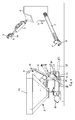
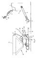
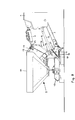
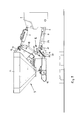
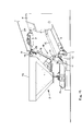
- Fig. 1 to 13 is the rear of the tractor with a power take-off shaft 2 and the horizontally spaced lower links 3 and an intermediate middle, but higher arranged upper link 4 shown.
- the lower links 3 are hydraulically pivotable on the tractor and the upper link 4 articulated.
- the lower links 3 each have an upwardly open catching mouth 5 with a lock 6, the upper link 4 a downwardly open catching mouth 7 with lock 8.
- the latches 6 and 8 are each part of a quick coupler fuse.
- Fig. 1 to 13 also show an attachment 9 in the form of a fertilizer spreader with a frame 10 and a fertilizer tank 11.
- the frame 10 includes, among other things substantially upright frame parts 12 and 13. At the lower 12 of these two frame parts are - not visible in the drawing - lower link connections in shape of bolts and the upper frame part 13, a top link terminal 14 in the form of a bolt set. If the attachment is equipped with a gearbox for driving the spreading discs, it has a telescopic articulated shaft 15, which is connected to the PTO shaft 2 of the tractor.
- a support device 16 is mounted, which has a rocker 17, a coupling 18 and a crank 19. Further, the support device includes a tensioning device - in the embodiment shown in the form of a tension spring 20 - on the one hand device-mounted, on the other hand provided with a handle 21 for clamping.
- the rocker 17 is connected to the coupling 18 via a knee joint 22, while the coupling 18 is connected to the crank 19 via a joint 24 arranged at a distance from the knee joint 22.
- the rocker is mounted at 23 and the crank 19 at 25 on the lower frame part 12.
- a mounting member 26 is attached near the capture mouth, whose function will be described later.
- Fig. 1 shows the starting position before the coupling process.
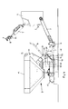
- the coupling 18 is folded by tensioning the spring 20 by means of the handle 21 in the direction of the tractor and finally arrives in the position according to Fig. 3 , At the same time or before the Unterscherkuppler Anlagenen be opened with the latch 6.
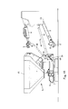
- Fig. 1 to 3 The tractor is shown at a greater distance to the attachment, which is only illustrative. He would also be in the same position Fig. 4 can be moved up and then the telescopic propeller shaft 5 is coupled to the PTO shaft 2 of the tractor. In this position, there is still enough space between the tractor tail 1 and tractor tire and attachment 9, so that the operator can enter the gap from the side. in the next phase according to Fig. 6 the top link 4 is hooked into the free end of the coupling 18.
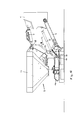
- the mounting part 26 has an upwardly extending recess.
- the Oberscherkuppler whiskey is opened with the bolt 8, for example by means of a pull rope eg from the tractor cab ( Fig. 7 ).
- the tractor continues to approach the attachment and pushes the coupling in the direction of the upper frame part 13.
- the coupling leads the catching mouth 7 of the upper link 4 along a curve whose upper vertex is above the upper link connecting horizontal plane. From the apex of the curve, the catch mouth on the falling branch of the curve on the upper link terminal 14 ( Fig. 8 ).
- the lower link 3 are locked to the lower link connections.
- Fig. 9 the front lower link is hidden.
- the lower links are raised in this tractor position and locked to the lower link connections.
- the supporting device 16 falls down under gravity.
- the attachment can now be moved to the working position ( Fig. 9 ) be raised.
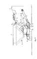
- the Oberscherschnellkupplertechnisch with the bolt 8 is released by means of the pull cable 27 from the tractor cab.
- the tensioning device By means of the tensioning device, the coupling 18 is raised and the catching jaw 6 of the upper link 4 is lifted out of the upper link connection 14 (FIG. Fig. 12 ).
- the coupling works in the direction of the tractor ( Fig. 13 ). In this position - after previously the lower links 3 have been solved - the top link 4 swung up in a tractor-side attitude. After uncoupling the propeller shaft 15 is back to the initial state Fig. 1 reached.
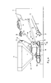
- Fig. 14 schematically shows the kinematics of the swingarm 17, coupling 18 and crank 19 existing support device 16.
- the free end 26 of the coupling 18 describes a curve, the upper vertex is above the upper link terminal 14 enclosing horizontal plane.
- the different positions that the coupling passes through are reproduced with dot-dash lines.
Abstract
Description
Die Erfindung betrifft eine Dreipunkt-Kuppelvorrichtung mit zwei an einem Traktor oder dergleichen in horizontalem Abstand voneinander angeordneten Unterlenkern mit je einem Fangmaul und einem höher und mittig liegenden Oberlenker mit Fangmaul für ein landwirtschaftliches Anbaugerät, das untere Anschlusspunkte für die Unterlenker und einen oberen Anschlusspunkt für den Oberlenker aufweist.The invention relates to a three-point coupling device with two on a tractor or the like at a horizontal distance from each other arranged lower links, each with a jaw and a higher and central upper link with catching mouth for an agricultural implement, the lower connection points for the lower links and an upper connection point for the Upper link has.
Die modulare Kombination Traktor mit Anbaugerät hat sich weltweit bewährt, weil sie durch die Trennung von Leistungsbereitstellung und Arbeitsmaschine im Verhältnis zu selbstfahrenden Spezialmaschinen bei der Nutzung von vielen Arbeitsmaschinen mit einem Traktor enorme Kostenvorteile ermöglicht.The modular combination tractor with attachment has proven itself worldwide because it allows for the separation of power supply and work machine in relation to self-propelled special machines in the use of many machines with a tractor enormous cost advantages.
Voraussetzung ist eine effektive und einfach zu handhabende, elektrische, hydraulische und mechanische Leistungs-übertragungsschnittstelle als auch Anbauschnittstelle zwischen dem Traktor und dem Anbaugerät.The prerequisite is an effective and easy-to-use, electrical, hydraulic and mechanical power transmission interface as well as an attachment interface between the tractor and the attachment.
Für die Anbauschnittstelle hat sich weltweit der sogenannte Dreipunkt nach ISO 730 eingeführt. Mittels ver- und entriegelbarer Schnellkuppler in den Unterlenkern und dem längenverstellbaren Oberlenker mit Ver- und Entriegelung lassen sich die Anbaugeräte an- und abbauen.The so-called three-point according to ISO 730 has been introduced worldwide for the attachment interface. By means of locking and unlocking quick coupler in the lower links and the length-adjustable upper link with locking and unlocking can be attached to the attachments and dismantle.
Aufgrund der begrenzten Achslasten auf der Hinterachse des Traktors und der Mindestlast auf der Vorderachse weisen die Anbaugeräte zur Erzielung einer hohen Nutzlast, z.B. bei Anbau-Düngerstreuern, recht kurze Unterlenkeranschlüsse auf, wodurch sie sehr dicht zur Hinterachse an den Traktor angebaut werden können. Wenn jedoch die Unterlenker des Traktors bei gleichzeitig großer Bereifung recht kurz sind, dann ist der Anbauraum zwischen Traktor und Anbaugerät eingeschränkt. Zwar können die elektrischen, hydraulischen und mit der neuerdings verfügbaren längenverstellbaren Gelenkwelle (Telespace) auch die mechanischen Leistungsübertragungselemente in größerem Abstand von Traktor und Anbaugerät gekuppelt werden. Dadurch kann der Bediener bequem zwischen Traktor und Anbaugerät stehen. Auch lassen sich die Unterlenker mittels der Schnellverschlüsse automatisch beim Rückwärtsfahren mit den Unterlenkeranschlüssen des Anbaugerätes verbinden. Zum Einhängen des Oberlenkers an den Oberlenkeranschluss des Anbaugerätes muss der Bediener jedoch zwischen Anbaugerät und Traktor treten. Es kann dann vorkommen, dass nur wenig Platz zwischen den Traktorreifen und dem Anbaugerät bleibt. Der Bediener gelangt dann nur sehr unkomfortabel in den Freiraum zwischen Traktor und Anbaugerät.Due to the limited axle loads on the rear axle of the tractor and the minimum load on the front axle, the attachments have to provide a high payload, e.g. In cultivation fertilizer spreaders, quite short lower link connections on which they can be attached very close to the rear axle to the tractor. However, if the lower links of the tractor are relatively short with large tires at the same time, the space between the tractor and attachment is limited. Although the electric, hydraulic and with the recently available adjustable length drive shaft (Telespace) and the mechanical power transmission elements can be coupled at a greater distance from the tractor and attachment. This allows the operator to stand comfortably between the tractor and the implement. The lower links can also be automatically connected to the lower link connections of the attachment when reversing using the quick-release fasteners. To mount the top link to the top link of the attachment, however, the operator must step between the implement and the tractor. It can then happen that only little space remains between the tractor tire and the attachment. The operator then gets very uncomfortable in the space between the tractor and implement.
Es ist eine Kuppelvorrichtung bekannt (
Es sind weiterhin bereits Elemente zur traktorseitigen Fixierung des Oberlenkers vorgeschlagen worden (
Schließlich ist aus der Praxis ein getrennter Dreipunkt-Rahmen bekannt, der in das Anbaugerät eingeklinkt ist. Er wird aus dem Anbaugerät ausgeklinkt und in die Unterlenker und den Oberlenker des Traktors eingehängt. Anschließend können alle Energieanschlüsse im Freiraum vorgenommen werden. Zum Schluss fährt der Fahrer mit dem Traktor an das Anbaugerät heran und hängt den Dreipunkt-Rahmen ein. Hierbei ist es sehr nachteilig und unkomfortabel, dass der schwere Dreipunkt-Rahmen mit einem Gewicht von ca. 30 bis 40 kg ausgehängt und in die Unterlenker und den Oberlenker eingehängt werden muss (Werbeschrift VICONTACT Ausgabe 14 ohne Druckvermerk). Beim Abbau ist dann wieder der umgekehrte Vorgang durchzuführen.Finally, from practice a separate three-point frame is known, which is latched into the attachment. It is disengaged from the attachment and hung in the lower link and the upper link of the tractor. Subsequently, all energy connections can be made in the free space. Finally, the driver approaches the implement with the tractor and hangs the three-point frame. It is very disadvantageous and uncomfortable that the heavy three-point frame with a weight of about 30 to 40 kg posted and suspended in the lower link and the top link must (advertising VICONTACT
Der Erfindung liegt die Aufgabe zugrunde, eine Kupplungsvorrichtung zu schaffen, bei der nach dem Ankuppeln der Unterlenker ein Betreten des Raums zwischen denselben zum Einhängen des Oberlenkers nicht erforderlich ist. Die Vorrichtung soll außerdem kostengünstig herstellbar sein. Ferner sollen die statischen und dynamischen Kräfte am Oberlenkeranschlusspunkt problemlos aufgenommen werden.The invention has for its object to provide a coupling device in which, after the coupling of the lower link, entering the space between them is not required for attaching the upper link. The device should also be inexpensive to produce. Furthermore, the static and dynamic forces at the top link connection point should be easily absorbed.
Bei einer Vorrichtung gemäß dem Oberbegriff des Anspruchs 1 wird diese Aufgabe dadurch gelöst, dass am Anbaugerät eine Stützvorrichtung begrenzt gelenkig angeordnet ist, die beim Ankuppeln das Fangmaul des Oberlenkers auf einer Kurve mit einem oberhalb der den Anschlusspunkt einschließenden Horizontalebene liegenden Scheitel von oben her in den Anschlusspunkt eingreifend führt, wobei das Fangmaul des Oberlenkers und das Fangmaul beider Unterlenker in der Kupplungsposition durch Schnellkupplersicherungen an den Anschlusspunkten verriegelt sind.In a device according to the preamble of
Die erfindungsgemäß vorgesehene Stützvorrichtung sorgt dafür, dass das Fangmaul des Oberlenkers auf einer Kurve geführt wird, von deren Scheitel aus das Fangmaul von oben her in den Oberlenkeranschluss einfädelt. Dies geschieht automatisch bei Rückwärtsfahrt des Traktors.The inventively provided support device ensures that the jaw of the upper link is guided on a curve, from the apex threading the jaw from above into the upper link terminal. This happens automatically when the tractor is reversing.
In bevorzugter Ausführung ist vorgesehen, dass die Stützvorrichtung eine Schwinge, eine Koppel und eine Kurbel aufweist, die für die Kurvenführung des am freien Ende der Koppel eingehängten Oberlenkers im Bereich des Fangmauls sorgt.In a preferred embodiment, it is provided that the support device comprises a rocker, a coupling and a crank, which ensures the curve guidance of the hinged at the free end of the coupling upper link in the region of the catching mouth.
Schwinge, Koppel und Kurbel bilden die kinematischen Elemente, um die Kurvenführung für das Fangmaul des Oberlenkers zu verwirklichen.Rocker, coupling and crank form the kinematic elements to realize the curve guide for the catching mouth of the upper link.
In weiterer Ausgestaltung der Kinematik ist vorgesehen, dass die Schwinge am Anbaugerät gelenkig gelagert und über ein Kniegelenk mit der Koppel verbunden ist, und dass die Kurbel am Anbaugerät gelagert ist und über ein Gelenk an der Koppel deren freies Ende auf der Kurve führt.In a further embodiment of the kinematics is provided that the rocker is mounted articulated on the attachment and connected via a knee joint with the coupling, and that the crank is mounted on the attachment and via a joint on the coupling whose free end leads to the curve.
In der zum Traktor hin ausgeklappten Position befindet sich die Koppel der Stützvorrichtung in Bereitschaftsstellung.In the folded-out position to the tractor is the coupling of the support device in the ready position.
Es ist weiterhin vorgesehen, dass die Koppel mit ihrem freien Ende in ein an der Unterseite des Oberlenkers im Bereich des Fangmauls angeordnetes Montageteil eingreift und über dieses das Fangmaul verrutschungssicher auf der Kurve von oben her auf den Oberlenkeranschluss führt.It is further contemplated that the coupling engages with its free end in a arranged on the underside of the upper link in the region of the jaw mounting part and over this the catch mouth slipping safely on the curve from above leads to the upper link connection.
Die mit ihrem freien Ende in das Montageteil eingreifende Koppel wird aus ihrer ausgeklappten Position bei Rückwärtsfahrt des Traktors zum Anbaugerät hin verschwenkt und führt dabei das Fangmaul des Oberlenkers in der Kurve in den Oberlenkeranschluss ein.The engaging with its free end in the mounting part coupling is pivoted from its unfolded position when reversing the tractor to the attachment out, thereby leading the jaw of the upper link in the curve in the upper link connection.
Vorzugsweise ist eine die Stützvorrichtung belastende Spannvorrichtung vorgesehen, die im einfachsten Fall eine vor dem Kuppelvorgang von Hand zu spannende Zugfeder aufweist, die einerseits am Anbaugerät eingehängt ist und andererseits an einem von der Koppel mitgeführten Teil jenseits des Gelenks der Koppel am Anbaugerät angreift.Preferably, a stressing the support device clamping device is provided, which in the simplest case has a tensioning spring before the dome operation by hand, which is mounted on the one hand on the attachment and on the other hand engages a carried by the coupling part beyond the joint of the coupling on the attachment.
Die Spannvorrichtung wird vor dem Kuppelvorgang aktiviert beispielsweise, wie bereits gesagt, von Hand vorgespannt. Beim Entkuppeln ist mittels der Spannvorrichtung das Fangmaul des Oberlenkers aus dem Oberlenkeranschluss aushebbar.The clamping device is activated before the dome operation, for example, as already mentioned, biased by hand. When decoupling the jaw of the upper link from the top link terminal can be lifted by means of the clamping device.
Der Oberlenker mit dem Montageteil verlässt bei Vorwärtsfahrt des Traktors nach Überschreiten des Scheitels der Kurve das freie Ende der Koppel und die Stützvorrichtung kehrt in ihre Ausgangslage zurück, bei der die Spannvorrichtung entspannt ist.The top link with the mounting part leaves when driving forward of the tractor after exceeding the apex of the curve, the free end of the coupling and the support device returns to its original position, in which the tensioning device is relaxed.
In vorteilhafter Ausführung ist ein von der Traktorkabine aus zu betätigendes Zugseil zur Entriegelung der Oberlenkeranschlusskupplersicherung vorgesehen. Desgleichen kann ein Zugseil zur Entriegelung der Spannvorrichtung vorgesehen sein.In an advantageous embodiment, a traction cable to be actuated from the tractor cab is provided for unlocking the upper link connecting coupler securing device. Likewise, a pull rope may be provided for unlocking the tensioning device.
Im Abwandlung hierzu kann statt des Zugseils zur Entriegelung der Oberlenkerschnellkupplersicherung ein elektrischer oder hydraulischer Aktuator vorgesehen sein. Ein eben solcher Aktuator kann statt des Zugseils zur Entriegelung der Spannvorrichtung vorgesehen sein.In a modification to this, instead of the traction cable for unlocking the top link quick coupler securing an electric or hydraulic actuator may be provided. A just such actuator may be provided instead of the pull cable for unlocking the tensioning device.
Der Aktuator zur Entriegelung der Spannvorrichtung und/oder der Aktuator zur Entriegelung der Oberlenkerschnellkupplersicherung können über ein Bedienterminal betätigbar sein.The actuator for unlocking the tensioning device and / or the actuator for unlocking the top link quick coupler can be actuated via a control terminal.
Als Bedienterminal kann auch dasjenige des Anbaugerätes oder des Traktors eingesetzt werden.As an operator terminal and that of the attachment or the tractor can be used.
In Abwandlung hierzu können einer oder beide Aktuatoren mit einer drahtlosen Fernbedienung betätigbar sein.Alternatively, one or both actuators may be operable with a wireless remote control.
Gemäß einem Ausführungsbeispiel ist vorgesehen, dass am Montageteil an der Unterseite des Oberlenkers auch der Aktuator für die Entriegelung der Oberlenkerschnellkupplersicherung integriert ist.According to one embodiment, it is provided that the actuator for unlocking the top link quick coupler is integrated on the mounting part on the underside of the upper link.
Oberlenker sind in der Regel längenverstellbar. Dies kann hydraulisch geschehen oder aber mittels Gewinde. In letzterem Fall sieht die Erfindung vor, dass die passende Einbaulänge vor dem Anbau für das entsprechende Anbaugerät festlegbar ist.Upper links are usually adjustable in length. This can be done hydraulically or by means of thread. In the latter case, the invention provides that the appropriate installation length before attachment for the corresponding attachment can be fixed.
Hierzu kann ein Messstab am Anbaugerät angebracht sein, mittels dessen die Einbaulänge des Oberlenkers vor dem Kuppelvorgang einstellbar ist.For this purpose, a measuring rod may be attached to the attachment, by means of which the installation length of the upper link is adjustable before the dome operation.
Stattdessen kann auch die Einbaulänge des Oberlenkers durch eine Markierung am Anbaugerät vorgemerkt sein, so dass der Bediener beispielsweise mittels eines Maßstabs die Einbaulänge einstellen kann.Instead, the installation length of the upper link can be marked by a mark on the attachment, so that the operator can set the installation length, for example by means of a scale.
Gemäß einer Alternative ist vorgesehen, dass am Oberlenker eine Markierung oder ein angebautes Markierungselement angebracht ist, die die zum Anbaugerät passende Einbaulänge anzeigt. Schließlich kann stattdessen vorgesehen sein, dass im Oberlenker ein Sensor eingebaut ist, mit dem die optimale Position bzw. Einbaulänge automatisiert angefahren wird.According to an alternative, it is provided that a marker or a mounted marking element is attached to the top link, which indicates the fitting length suitable for the attachment. Finally, it may be provided instead that a sensor is installed in the top link, with which the optimal position or installation length is automatically approached.
Nachstehend ist die Erfindung anhand eines in der Zeichnung wiedergegebenen Ausführungsbeispiels unter Wiedergabe mehrerer Positionen beim Ankuppeln und Abkuppeln des Anbaugerätes beschrieben. In der Zeichnung zeigen:
- Fig. 1 bis 13
- verschiedene Phasen beim An- und Abkuppeln des Anbaugerätes; und
- Fig. 14
- verschiedene Positionen der Koppel der Stützvorrichtung zwischen dem herausgeklappten Zustand der Koppel und der Übergabeposition des Fangmauls des Oberlenkers an den Oberlenkeranschluss in schematischer Darstellung.
- Fig. 1 to 13
- different phases when connecting and disconnecting the attachment; and
- Fig. 14
- various positions of the coupling of the support device between the folded-out state of the coupling and the transfer position of the jaw of the upper link to the upper link connection in a schematic representation.
In der
An dem unteren Rahmenteil 12 ist eine Stützvorrichtung 16 gelagert, die eine Schwinge 17, eine Koppel 18 und eine Kurbel 19 aufweist. Ferner gehört zur Stützvorrichtung eine Spannvorrichtung - beim gezeigten Ausführungsbeispiel in Form einer Zugfeder 20 - die einerseits gerätsseitig eingehängt, andererseits mit einer Handhabe 21 zum Spannen versehen ist. Die Schwinge 17 ist mit der Koppel 18 über ein Kniegelenk 22 verbunden, während die Koppel 18 mit der Kurbel 19 über eine mit Abstand vom Kniegelenk 22 angeordnetes Gelenk 24 verbunden ist. Die Schwinge ist bei 23 und die Kurbel 19 bei 25 am unteren Rahmenteil 12 gelagert.On the
An der Unterseite des Oberlenkers 4 ist nahe dem Fangmaul ein Montageteil 26 befestigt, dessen Funktion später beschrieben wird.At the bottom of the
In
Anschließend wird die Oberlenkerkupplersicherung mit dem Riegel 8 beispielsweise mittels eines Zugseils z.B. von der Traktorkabine aus geöffnet (
Damit ist der Kuppelvorgang abgeschlossen. Die Stützvorrichtung 16 fällt unter Schwerkraft nach unten. Das Anbaugerät kann nun in die Arbeitsposition (
Bei dem mit der Phase gemäß
Die Oberlenkerschnellkupplersicherung mit dem Riegel 8 wird mittels des Zugseils 27 von der Traktorkabine aus gelöst. Mittels der Spannvorrichtung wird die Koppel 18 angehoben und das Fangmaul 6 des Oberlenkers 4 aus dem Oberlenkeranschluss 14 ausgehoben (
- 11
- Traktorheckrear of the tractor
- 22
- ZapfwellePTO
- 33
- Unterlenkerlower link
- 44
- Oberlenkertop link
- 55
- Unterlenker-FangmaulLower link Maul
- 66
- Riegelbars
- 77
- Oberlenker-FangmaulUpper arm-jaw
- 88th
- Riegelbars
- 99
- Anbaugerätattachment
- 1010
- Rahmenframe
- 1111
- Behältercontainer
- 1212
- unteres aufrechtes Rahmenteillower upright frame part
- 1313
- oberes aufrechtes RahmenteilUpper upright frame part
- 1414
- OberlenkeranschlussTop link connection
- 1515
- Gelenkwellepropeller shaft
- 1616
- Stützvorrichtungsupport device
- 1717
- Schwingewing
- 1818
- Koppelpaddock
- 1919
- Kurbelcrank
- 2020
- Spannvorrichtungjig
- 2121
- Handhabehandle
- 2222
- Kniegelenkknee
- 2323
- Lager Schwinge/RahmenBearing swingarm / frame
- 2424
- Gelenk-Koppel/KurbelJoint coupling / crank
- 2525
- Lager Kurbel/RahmenBearing crank / frame
- 2626
- freies, oberes Ende von 18free, upper end of 18
- 2727
- Zugseilrope
- 2828
- Montageteil an 4Mounting part to 4
Claims (21)
dadurch gekennzeichnet, dass die Schwinge (17) am Anbaugerät (9) gelenkig gelagert und über ein Kniegelenk (22) mit der Koppel (18) verbunden ist, und dass die Kurbel (19) am Anbaugerät (9) gelagert ist und über ein Gelenk (24) an der Koppel (18) deren freies Ende (28) auf der Kurve führt.Coupling device according to one of claims 1 or 2,
characterized in that the rocker (17) articulated on the attachment (9) and connected via a knee joint (22) with the coupling (18), and that the crank (19) is mounted on the attachment (9) and a joint (24) at the coupling (18) whose free end (28) leads to the curve.
dadurch gekennzeichnet, dass beim Entkuppeln mittels der Spannvorrichtung (20) das Fangmaul (7) des Oberlenkers (4) aus dem Oberlenkeranschluss (14) aushebbar ist.Coupling device according to one of claims 1 to 12,
characterized in that the intercepting mouth (7) of the upper link (4) from the upper link connection (14) can be lifted during uncoupling means of the clamping device (20).
dadurch gekennzeichnet, dass am Montageteil (28) an der Unterseite des Oberlenkers (4) auch der Aktuator für die Entriegelung der Oberlenkerschnellkupplersicherung integriert ist.Coupling device according to one of claims 1 to 15,
characterized in that on the mounting part (28) on the underside of the upper link (4) and the actuator for unlocking the upper link quick coupler securing is integrated.
dadurch gekennzeichnet, dass bei einem mittels Gewinde verstellbaren Oberlenker (4) die passende Einbaulänge vor dem Anbau für das entsprechende Anbaugerät (1) festlegbar ist.Coupling device according to one of claims 1 to 16,
characterized in that in a threaded adjustable upper link (4), the appropriate installation length before attachment for the corresponding attachment (1) can be fixed.
Applications Claiming Priority (1)
| Application Number | Priority Date | Filing Date | Title |
|---|---|---|---|
| DE201010049167 DE102010049167A1 (en) | 2010-10-21 | 2010-10-21 | Three-point coupling device |
Publications (2)
| Publication Number | Publication Date |
|---|---|
| EP2443916A1 true EP2443916A1 (en) | 2012-04-25 |
| EP2443916B1 EP2443916B1 (en) | 2014-01-01 |
Family
ID=45445694
Family Applications (1)
| Application Number | Title | Priority Date | Filing Date |
|---|---|---|---|
| EP20110008354 Active EP2443916B1 (en) | 2010-10-21 | 2011-10-17 | Three point coupling device |
Country Status (2)
| Country | Link |
|---|---|
| EP (1) | EP2443916B1 (en) |
| DE (1) | DE102010049167A1 (en) |
Cited By (4)
| Publication number | Priority date | Publication date | Assignee | Title |
|---|---|---|---|---|
| ES2557058A1 (en) * | 2015-09-29 | 2016-01-21 | Exel Industries | Device for connecting an agricultural accessory to a tractor agricultural vehicle (Machine-translation by Google Translate, not legally binding) |
| DE102015103925A1 (en) * | 2015-03-17 | 2016-10-06 | Jan-Hendrik Wacker | Hydraulic top link, hydraulic three-point suspension and method for coupling a utility unit to a commercial vehicle |
| EP3440907A1 (en) * | 2017-08-11 | 2019-02-13 | Vermeer Manufacturing Company | Self-propelled vehicles with extendable devices |
| FR3109259A1 (en) * | 2020-04-20 | 2021-10-22 | Exel Industries | AGRICULTURAL SPRAYING UNIT CARRIED BY AN AGRICULTURAL MACHINE BY MEANS OF A HITCHING SYSTEM |
Families Citing this family (1)
| Publication number | Priority date | Publication date | Assignee | Title |
|---|---|---|---|---|
| DE102016217944A1 (en) | 2016-09-20 | 2018-03-22 | Deere & Company | Upper link for a three-point linkage of an agricultural tractor |
Citations (6)
| Publication number | Priority date | Publication date | Assignee | Title |
|---|---|---|---|---|
| US3220751A (en) * | 1962-05-21 | 1965-11-30 | Massey Ferguson Inc | Quick hitch with toggle action |
| DE3812198A1 (en) | 1988-04-13 | 1989-10-26 | Walterscheid Gmbh Jean | THREE-POINT ATTACHMENT DEVICE |
| EP1982855A1 (en) | 2007-04-20 | 2008-10-22 | Deere & Company | Linkage device for a three-point trailer coupler |
| EP1982854A1 (en) | 2007-04-20 | 2008-10-22 | Deere & Company | Linkage device for a three-point coupling device |
| EP1982853A1 (en) | 2007-04-20 | 2008-10-22 | Deere & Company | Linkage device for a three point trailer device |
| EP2225925A2 (en) * | 2009-03-02 | 2010-09-08 | LH Lift Oy | Arrangement in connection with a three-point hitch device and adapter part for a work machine for coupling it to a three-point hitch device |
Family Cites Families (2)
| Publication number | Priority date | Publication date | Assignee | Title |
|---|---|---|---|---|
| DE1208108B (en) * | 1964-12-08 | 1965-12-30 | Ventzki G M B H | Safety clutch |
| NL6614855A (en) * | 1966-10-21 | 1968-04-22 |
-
2010
- 2010-10-21 DE DE201010049167 patent/DE102010049167A1/en not_active Withdrawn
-
2011
- 2011-10-17 EP EP20110008354 patent/EP2443916B1/en active Active
Patent Citations (6)
| Publication number | Priority date | Publication date | Assignee | Title |
|---|---|---|---|---|
| US3220751A (en) * | 1962-05-21 | 1965-11-30 | Massey Ferguson Inc | Quick hitch with toggle action |
| DE3812198A1 (en) | 1988-04-13 | 1989-10-26 | Walterscheid Gmbh Jean | THREE-POINT ATTACHMENT DEVICE |
| EP1982855A1 (en) | 2007-04-20 | 2008-10-22 | Deere & Company | Linkage device for a three-point trailer coupler |
| EP1982854A1 (en) | 2007-04-20 | 2008-10-22 | Deere & Company | Linkage device for a three-point coupling device |
| EP1982853A1 (en) | 2007-04-20 | 2008-10-22 | Deere & Company | Linkage device for a three point trailer device |
| EP2225925A2 (en) * | 2009-03-02 | 2010-09-08 | LH Lift Oy | Arrangement in connection with a three-point hitch device and adapter part for a work machine for coupling it to a three-point hitch device |
Cited By (6)
| Publication number | Priority date | Publication date | Assignee | Title |
|---|---|---|---|---|
| DE102015103925A1 (en) * | 2015-03-17 | 2016-10-06 | Jan-Hendrik Wacker | Hydraulic top link, hydraulic three-point suspension and method for coupling a utility unit to a commercial vehicle |
| ES2557058A1 (en) * | 2015-09-29 | 2016-01-21 | Exel Industries | Device for connecting an agricultural accessory to a tractor agricultural vehicle (Machine-translation by Google Translate, not legally binding) |
| EP3440907A1 (en) * | 2017-08-11 | 2019-02-13 | Vermeer Manufacturing Company | Self-propelled vehicles with extendable devices |
| US10980183B2 (en) | 2017-08-11 | 2021-04-20 | Vermeer Manufacturing Company | Self-propelled vehicles with extendable devices |
| FR3109259A1 (en) * | 2020-04-20 | 2021-10-22 | Exel Industries | AGRICULTURAL SPRAYING UNIT CARRIED BY AN AGRICULTURAL MACHINE BY MEANS OF A HITCHING SYSTEM |
| EP3900533A1 (en) * | 2020-04-20 | 2021-10-27 | Exel Industries | Agricultural spray towed by a farm vehicle by means of a coupling system |
Also Published As
| Publication number | Publication date |
|---|---|
| DE102010049167A1 (en) | 2012-04-26 |
| EP2443916B1 (en) | 2014-01-01 |
Similar Documents
| Publication | Publication Date | Title |
|---|---|---|
| EP2443916B1 (en) | Three point coupling device | |
| WO2006111505A1 (en) | Three-point linkage for an agricultural or industrial utility vehicle | |
| DE2403077C3 (en) | Ball head coupling for connecting a towing vehicle with a towed vehicle | |
| DE1958640A1 (en) | Tractor coupling | |
| DE4412115B4 (en) | drive connection | |
| EP2708386B1 (en) | Coupling device for a motor vehicle | |
| DE19857167A1 (en) | Telescopic device attachment of a motor vehicle | |
| US3889980A (en) | Three-point attachment device particularly for a tractor | |
| DE2403004A1 (en) | DEVICE FOR CONNECTING A TOWED VEHICLE TO A PULLING VEHICLE | |
| EP3753385B1 (en) | Supporting structure for connecting two agricultural implements to a tractor and agricultural implement | |
| DE1455494A1 (en) | Three-point linkage with frame for connecting agricultural equipment to a tractor | |
| DE1059297B (en) | Coupling device for tractor | |
| DE1755143A1 (en) | tractor | |
| DE952219C (en) | Arrangement of interchangeable plows on a three-point hitch | |
| DE1557669C2 (en) | Device for connecting work equipment to the three-point linkage of tractors, which is provided with coupling hooks | |
| EP1008283A1 (en) | Method and device for hitching an implement | |
| EP1852012B1 (en) | Jiggle device for moving tree trunks | |
| DE2841022A1 (en) | Hinging component lock for vehicle lifting platform - has axis pin with portion sliding into engagement with coupling member on lifting | |
| DE1582169A1 (en) | Harvest recovery machine, especially field harvester | |
| DE19634323C2 (en) | Device for holding a cardan shaft | |
| EP3398903B1 (en) | Vehicle, tool and method for above ground mounting of tubes | |
| DE2247903C3 (en) | Device for coupling, in particular a tractor, to an agricultural implement or trailer | |
| DE1251069B (en) | Quick coupling for attachments with coupling bolts on tractors | |
| DE3643209A1 (en) | Connection of the upper link of a three-point mounting device of tractors for agriculture, forestry and commerce | |
| DE885201C (en) | Trailer coupling for tractor |
Legal Events
| Date | Code | Title | Description |
|---|---|---|---|
| AK | Designated contracting states |
Kind code of ref document: A1 Designated state(s): AL AT BE BG CH CY CZ DE DK EE ES FI FR GB GR HR HU IE IS IT LI LT LU LV MC MK MT NL NO PL PT RO RS SE SI SK SM TR |
|
| AX | Request for extension of the european patent |
Extension state: BA ME |
|
| PUAI | Public reference made under article 153(3) epc to a published international application that has entered the european phase |
Free format text: ORIGINAL CODE: 0009012 |
|
| 17P | Request for examination filed |
Effective date: 20121004 |
|
| RIN1 | Information on inventor provided before grant (corrected) |
Inventor name: GUSHURST, HANS Inventor name: SCHAEFER, FABIAN Inventor name: STOECKLIN, VOLKER, M.SC. Inventor name: DOLL, FRANZ Inventor name: RAUCH, NORBERT, DR.H.C. |
|
| GRAP | Despatch of communication of intention to grant a patent |
Free format text: ORIGINAL CODE: EPIDOSNIGR1 |
|
| RIC1 | Information provided on ipc code assigned before grant |
Ipc: A01B 59/06 20060101AFI20121221BHEP |
|
| GRAP | Despatch of communication of intention to grant a patent |
Free format text: ORIGINAL CODE: EPIDOSNIGR1 |
|
| INTG | Intention to grant announced |
Effective date: 20130729 |
|
| GRAS | Grant fee paid |
Free format text: ORIGINAL CODE: EPIDOSNIGR3 |
|
| GRAA | (expected) grant |
Free format text: ORIGINAL CODE: 0009210 |
|
| AK | Designated contracting states |
Kind code of ref document: B1 Designated state(s): AL AT BE BG CH CY CZ DE DK EE ES FI FR GB GR HR HU IE IS IT LI LT LU LV MC MK MT NL NO PL PT RO RS SE SI SK SM TR |
|
| REG | Reference to a national code |
Ref country code: GB Ref legal event code: FG4D Free format text: NOT ENGLISH |
|
| REG | Reference to a national code |
Ref country code: CH Ref legal event code: EP |
|
| REG | Reference to a national code |
Ref country code: IE Ref legal event code: FG4D Free format text: LANGUAGE OF EP DOCUMENT: GERMAN |
|
| REG | Reference to a national code |
Ref country code: DE Ref legal event code: R096 Ref document number: 502011001909 Country of ref document: DE Effective date: 20140213 |
|
| REG | Reference to a national code |
Ref country code: AT Ref legal event code: REF Ref document number: 647184 Country of ref document: AT Kind code of ref document: T Effective date: 20140215 |
|
| REG | Reference to a national code |
Ref country code: NL Ref legal event code: VDEP Effective date: 20140101 |
|
| REG | Reference to a national code |
Ref country code: LT Ref legal event code: MG4D |
|
| PG25 | Lapsed in a contracting state [announced via postgrant information from national office to epo] |
Ref country code: IS Free format text: LAPSE BECAUSE OF FAILURE TO SUBMIT A TRANSLATION OF THE DESCRIPTION OR TO PAY THE FEE WITHIN THE PRESCRIBED TIME-LIMIT Effective date: 20140501 Ref country code: LT Free format text: LAPSE BECAUSE OF FAILURE TO SUBMIT A TRANSLATION OF THE DESCRIPTION OR TO PAY THE FEE WITHIN THE PRESCRIBED TIME-LIMIT Effective date: 20140101 |
|
| PG25 | Lapsed in a contracting state [announced via postgrant information from national office to epo] |
Ref country code: SE Free format text: LAPSE BECAUSE OF FAILURE TO SUBMIT A TRANSLATION OF THE DESCRIPTION OR TO PAY THE FEE WITHIN THE PRESCRIBED TIME-LIMIT Effective date: 20140101 Ref country code: CY Free format text: LAPSE BECAUSE OF FAILURE TO SUBMIT A TRANSLATION OF THE DESCRIPTION OR TO PAY THE FEE WITHIN THE PRESCRIBED TIME-LIMIT Effective date: 20140101 Ref country code: PT Free format text: LAPSE BECAUSE OF FAILURE TO SUBMIT A TRANSLATION OF THE DESCRIPTION OR TO PAY THE FEE WITHIN THE PRESCRIBED TIME-LIMIT Effective date: 20140502 Ref country code: NL Free format text: LAPSE BECAUSE OF FAILURE TO SUBMIT A TRANSLATION OF THE DESCRIPTION OR TO PAY THE FEE WITHIN THE PRESCRIBED TIME-LIMIT Effective date: 20140101 Ref country code: ES Free format text: LAPSE BECAUSE OF FAILURE TO SUBMIT A TRANSLATION OF THE DESCRIPTION OR TO PAY THE FEE WITHIN THE PRESCRIBED TIME-LIMIT Effective date: 20140101 Ref country code: FI Free format text: LAPSE BECAUSE OF FAILURE TO SUBMIT A TRANSLATION OF THE DESCRIPTION OR TO PAY THE FEE WITHIN THE PRESCRIBED TIME-LIMIT Effective date: 20140101 |
|
| PG25 | Lapsed in a contracting state [announced via postgrant information from national office to epo] |
Ref country code: LV Free format text: LAPSE BECAUSE OF FAILURE TO SUBMIT A TRANSLATION OF THE DESCRIPTION OR TO PAY THE FEE WITHIN THE PRESCRIBED TIME-LIMIT Effective date: 20140101 Ref country code: RS Free format text: LAPSE BECAUSE OF FAILURE TO SUBMIT A TRANSLATION OF THE DESCRIPTION OR TO PAY THE FEE WITHIN THE PRESCRIBED TIME-LIMIT Effective date: 20140101 Ref country code: HR Free format text: LAPSE BECAUSE OF FAILURE TO SUBMIT A TRANSLATION OF THE DESCRIPTION OR TO PAY THE FEE WITHIN THE PRESCRIBED TIME-LIMIT Effective date: 20140101 |
|
| REG | Reference to a national code |
Ref country code: DE Ref legal event code: R097 Ref document number: 502011001909 Country of ref document: DE |
|
| PG25 | Lapsed in a contracting state [announced via postgrant information from national office to epo] |
Ref country code: CZ Free format text: LAPSE BECAUSE OF FAILURE TO SUBMIT A TRANSLATION OF THE DESCRIPTION OR TO PAY THE FEE WITHIN THE PRESCRIBED TIME-LIMIT Effective date: 20140101 Ref country code: EE Free format text: LAPSE BECAUSE OF FAILURE TO SUBMIT A TRANSLATION OF THE DESCRIPTION OR TO PAY THE FEE WITHIN THE PRESCRIBED TIME-LIMIT Effective date: 20140101 Ref country code: RO Free format text: LAPSE BECAUSE OF FAILURE TO SUBMIT A TRANSLATION OF THE DESCRIPTION OR TO PAY THE FEE WITHIN THE PRESCRIBED TIME-LIMIT Effective date: 20140101 Ref country code: DK Free format text: LAPSE BECAUSE OF FAILURE TO SUBMIT A TRANSLATION OF THE DESCRIPTION OR TO PAY THE FEE WITHIN THE PRESCRIBED TIME-LIMIT Effective date: 20140101 |
|
| PLBE | No opposition filed within time limit |
Free format text: ORIGINAL CODE: 0009261 |
|
| STAA | Information on the status of an ep patent application or granted ep patent |
Free format text: STATUS: NO OPPOSITION FILED WITHIN TIME LIMIT |
|
| PG25 | Lapsed in a contracting state [announced via postgrant information from national office to epo] |
Ref country code: SK Free format text: LAPSE BECAUSE OF FAILURE TO SUBMIT A TRANSLATION OF THE DESCRIPTION OR TO PAY THE FEE WITHIN THE PRESCRIBED TIME-LIMIT Effective date: 20140101 Ref country code: PL Free format text: LAPSE BECAUSE OF FAILURE TO SUBMIT A TRANSLATION OF THE DESCRIPTION OR TO PAY THE FEE WITHIN THE PRESCRIBED TIME-LIMIT Effective date: 20140101 |
|
| 26N | No opposition filed |
Effective date: 20141002 |
|
| REG | Reference to a national code |
Ref country code: DE Ref legal event code: R097 Ref document number: 502011001909 Country of ref document: DE Effective date: 20141002 |
|
| PG25 | Lapsed in a contracting state [announced via postgrant information from national office to epo] |
Ref country code: MC Free format text: LAPSE BECAUSE OF FAILURE TO SUBMIT A TRANSLATION OF THE DESCRIPTION OR TO PAY THE FEE WITHIN THE PRESCRIBED TIME-LIMIT Effective date: 20140101 Ref country code: SI Free format text: LAPSE BECAUSE OF FAILURE TO SUBMIT A TRANSLATION OF THE DESCRIPTION OR TO PAY THE FEE WITHIN THE PRESCRIBED TIME-LIMIT Effective date: 20140101 Ref country code: LU Free format text: LAPSE BECAUSE OF FAILURE TO SUBMIT A TRANSLATION OF THE DESCRIPTION OR TO PAY THE FEE WITHIN THE PRESCRIBED TIME-LIMIT Effective date: 20141017 |
|
| REG | Reference to a national code |
Ref country code: CH Ref legal event code: PL |
|
| PG25 | Lapsed in a contracting state [announced via postgrant information from national office to epo] |
Ref country code: BE Free format text: LAPSE BECAUSE OF NON-PAYMENT OF DUE FEES Effective date: 20141031 |
|
| REG | Reference to a national code |
Ref country code: IE Ref legal event code: MM4A |
|
| PG25 | Lapsed in a contracting state [announced via postgrant information from national office to epo] |
Ref country code: CH Free format text: LAPSE BECAUSE OF NON-PAYMENT OF DUE FEES Effective date: 20141031 Ref country code: LI Free format text: LAPSE BECAUSE OF NON-PAYMENT OF DUE FEES Effective date: 20141031 |
|
| PG25 | Lapsed in a contracting state [announced via postgrant information from national office to epo] |
Ref country code: IE Free format text: LAPSE BECAUSE OF NON-PAYMENT OF DUE FEES Effective date: 20141017 |
|
| REG | Reference to a national code |
Ref country code: FR Ref legal event code: PLFP Year of fee payment: 5 |
|
| PGFP | Annual fee paid to national office [announced via postgrant information from national office to epo] |
Ref country code: GB Payment date: 20151026 Year of fee payment: 5 |
|
| PG25 | Lapsed in a contracting state [announced via postgrant information from national office to epo] |
Ref country code: NO Free format text: LAPSE BECAUSE OF FAILURE TO SUBMIT A TRANSLATION OF THE DESCRIPTION OR TO PAY THE FEE WITHIN THE PRESCRIBED TIME-LIMIT Effective date: 20140401 Ref country code: SM Free format text: LAPSE BECAUSE OF FAILURE TO SUBMIT A TRANSLATION OF THE DESCRIPTION OR TO PAY THE FEE WITHIN THE PRESCRIBED TIME-LIMIT Effective date: 20140101 |
|
| PG25 | Lapsed in a contracting state [announced via postgrant information from national office to epo] |
Ref country code: IT Free format text: LAPSE BECAUSE OF FAILURE TO SUBMIT A TRANSLATION OF THE DESCRIPTION OR TO PAY THE FEE WITHIN THE PRESCRIBED TIME-LIMIT Effective date: 20140101 Ref country code: GR Free format text: LAPSE BECAUSE OF FAILURE TO SUBMIT A TRANSLATION OF THE DESCRIPTION OR TO PAY THE FEE WITHIN THE PRESCRIBED TIME-LIMIT Effective date: 20140402 Ref country code: BG Free format text: LAPSE BECAUSE OF FAILURE TO SUBMIT A TRANSLATION OF THE DESCRIPTION OR TO PAY THE FEE WITHIN THE PRESCRIBED TIME-LIMIT Effective date: 20140101 |
|
| PG25 | Lapsed in a contracting state [announced via postgrant information from national office to epo] |
Ref country code: HU Free format text: LAPSE BECAUSE OF FAILURE TO SUBMIT A TRANSLATION OF THE DESCRIPTION OR TO PAY THE FEE WITHIN THE PRESCRIBED TIME-LIMIT; INVALID AB INITIO Effective date: 20111017 Ref country code: TR Free format text: LAPSE BECAUSE OF FAILURE TO SUBMIT A TRANSLATION OF THE DESCRIPTION OR TO PAY THE FEE WITHIN THE PRESCRIBED TIME-LIMIT Effective date: 20140101 Ref country code: MT Free format text: LAPSE BECAUSE OF FAILURE TO SUBMIT A TRANSLATION OF THE DESCRIPTION OR TO PAY THE FEE WITHIN THE PRESCRIBED TIME-LIMIT Effective date: 20140101 |
|
| REG | Reference to a national code |
Ref country code: FR Ref legal event code: PLFP Year of fee payment: 6 |
|
| GBPC | Gb: european patent ceased through non-payment of renewal fee |
Effective date: 20161017 |
|
| PG25 | Lapsed in a contracting state [announced via postgrant information from national office to epo] |
Ref country code: GB Free format text: LAPSE BECAUSE OF NON-PAYMENT OF DUE FEES Effective date: 20161017 |
|
| REG | Reference to a national code |
Ref country code: FR Ref legal event code: PLFP Year of fee payment: 7 |
|
| REG | Reference to a national code |
Ref country code: AT Ref legal event code: MM01 Ref document number: 647184 Country of ref document: AT Kind code of ref document: T Effective date: 20161017 |
|
| PG25 | Lapsed in a contracting state [announced via postgrant information from national office to epo] |
Ref country code: AT Free format text: LAPSE BECAUSE OF NON-PAYMENT OF DUE FEES Effective date: 20161017 |
|
| PG25 | Lapsed in a contracting state [announced via postgrant information from national office to epo] |
Ref country code: MK Free format text: LAPSE BECAUSE OF FAILURE TO SUBMIT A TRANSLATION OF THE DESCRIPTION OR TO PAY THE FEE WITHIN THE PRESCRIBED TIME-LIMIT Effective date: 20140101 |
|
| REG | Reference to a national code |
Ref country code: FR Ref legal event code: PLFP Year of fee payment: 8 |
|
| PG25 | Lapsed in a contracting state [announced via postgrant information from national office to epo] |
Ref country code: AL Free format text: LAPSE BECAUSE OF FAILURE TO SUBMIT A TRANSLATION OF THE DESCRIPTION OR TO PAY THE FEE WITHIN THE PRESCRIBED TIME-LIMIT Effective date: 20140101 |
|
| P01 | Opt-out of the competence of the unified patent court (upc) registered |
Effective date: 20230425 |
|
| REG | Reference to a national code |
Ref country code: DE Ref legal event code: R081 Ref document number: 502011001909 Country of ref document: DE Owner name: RAUCH LANDMASCHINENFABRIK GESELLSCHAFT MIT BES, DE Free format text: FORMER OWNER: RAUCH LANDMASCHINENFABRIK GMBH, 76547 SINZHEIM, DE |
|
| PGFP | Annual fee paid to national office [announced via postgrant information from national office to epo] |
Ref country code: FR Payment date: 20231031 Year of fee payment: 13 Ref country code: DE Payment date: 20231010 Year of fee payment: 13 |