EP2441640A1 - Method for reinforcing structure for railway rolling stock and structure for railway rolling stock - Google Patents
Method for reinforcing structure for railway rolling stock and structure for railway rolling stock Download PDFInfo
- Publication number
- EP2441640A1 EP2441640A1 EP10785897A EP10785897A EP2441640A1 EP 2441640 A1 EP2441640 A1 EP 2441640A1 EP 10785897 A EP10785897 A EP 10785897A EP 10785897 A EP10785897 A EP 10785897A EP 2441640 A1 EP2441640 A1 EP 2441640A1
- Authority
- EP
- European Patent Office
- Prior art keywords
- fiber sheet
- plate
- bodyshell
- fiber
- disposing
- Prior art date
- Legal status (The legal status is an assumption and is not a legal conclusion. Google has not performed a legal analysis and makes no representation as to the accuracy of the status listed.)
- Withdrawn
Links
Images





Classifications
-
- B—PERFORMING OPERATIONS; TRANSPORTING
- B61—RAILWAYS
- B61D—BODY DETAILS OR KINDS OF RAILWAY VEHICLES
- B61D17/00—Construction details of vehicle bodies
- B61D17/005—Construction details of vehicle bodies with bodies characterised by use of plastics materials
-
- B—PERFORMING OPERATIONS; TRANSPORTING
- B61—RAILWAYS
- B61D—BODY DETAILS OR KINDS OF RAILWAY VEHICLES
- B61D17/00—Construction details of vehicle bodies
- B61D17/04—Construction details of vehicle bodies with bodies of metal; with composite, e.g. metal and wood body structures
-
- Y—GENERAL TAGGING OF NEW TECHNOLOGICAL DEVELOPMENTS; GENERAL TAGGING OF CROSS-SECTIONAL TECHNOLOGIES SPANNING OVER SEVERAL SECTIONS OF THE IPC; TECHNICAL SUBJECTS COVERED BY FORMER USPC CROSS-REFERENCE ART COLLECTIONS [XRACs] AND DIGESTS
- Y02—TECHNOLOGIES OR APPLICATIONS FOR MITIGATION OR ADAPTATION AGAINST CLIMATE CHANGE
- Y02T—CLIMATE CHANGE MITIGATION TECHNOLOGIES RELATED TO TRANSPORTATION
- Y02T30/00—Transportation of goods or passengers via railways, e.g. energy recovery or reducing air resistance
-
- Y—GENERAL TAGGING OF NEW TECHNOLOGICAL DEVELOPMENTS; GENERAL TAGGING OF CROSS-SECTIONAL TECHNOLOGIES SPANNING OVER SEVERAL SECTIONS OF THE IPC; TECHNICAL SUBJECTS COVERED BY FORMER USPC CROSS-REFERENCE ART COLLECTIONS [XRACs] AND DIGESTS
- Y10—TECHNICAL SUBJECTS COVERED BY FORMER USPC
- Y10T—TECHNICAL SUBJECTS COVERED BY FORMER US CLASSIFICATION
- Y10T156/00—Adhesive bonding and miscellaneous chemical manufacture
- Y10T156/10—Methods of surface bonding and/or assembly therefor
Definitions
- the present invention relates to a method for reinforcing a railcar bodyshell including a wave-shaped plate and a frame and to the railcar bodyshell.
- Railcar bodyshells made of stainless steel, aluminum, or the like have been conventionally known.
- a corrugated panel hereinafter referred to as a "thin wavy plate" which has a wave-shaped cross section and is small in thickness is used to reduce the weight of the railcar while maintaining the strength thereof.
- weak portions of the roof bodyshell and underframe of the railcar have been reinforced by, for example, welding of reinforcing plates so as to be increased in stiffness.
- the weak portion to be reinforced is a part of the thin wavy plate
- a reinforcing member for example, in the case of the welding, one problem is that manufacturing accuracy deteriorates by thermal distortion, and in the case of the bolts, another problem is that a bolt hole is damaged and this deteriorates seal performance (hereinafter referred to as "water-tightness") for preventing the ingress of water.
- water-tightness seal performance
- the weights of the roof board and the floor panel increase by reinforcement.
- each of PTLs 1 to 4 proposes a technique to use a carbon fiber reinforced resin for the outside plate and frame member of the railcar.
- the railcar bodyshell can be significantly reduced in weight.
- an object of the present invention is to appropriately maintaining the cost, recyclability, and manufacturing efficiency of the railcar bodyshell while improving the manufacturing accuracy and water-tightness thereof and reducing the carbody weight thereof.
- a railcar bodyshell reinforcing method of the present invention includes the steps of: in a bodyshell including a metal frame and a metal plate joined to the frame and formed such that a cross section thereof orthogonal to a railcar longitudinal direction has a wave shape, disposing a fiber sheet on at least a part of the plate; and forming a fiber reinforced resin member by bonding the fiber sheet to the part of the plate by an impregnated adhesive resin.
- the "fiber sheet” is a sheet which is formed such that fibers, such as carbon fibers, utilized in a fiber reinforced resin are formed like a cloth and which is not impregnated with a resin.
- the fiber sheet having flexibility is spread on a part of the metal plate having a wave-shaped cross section and is impregnated with and bonded by the impregnated adhesive resin.
- the fiber reinforced resin member bonded to the plate can be easily formed, and the bodyshell can be reinforced by a simple process while reducing the carbody weight thereof.
- the manufacturing accuracy does not deteriorate by the thermal distortion, and the water-tightness does not deteriorate by the damage on the bolt hole.
- the fiber sheet is disposed on a part of the plate, and the frame and plate that are major portions are made of metal, the cost and the recyclability can be appropriately maintained. As above, the cost, recyclability, and manufacturing efficiency of the railcar bodyshell can be appropriately maintained while improving the manufacturing accuracy and water-tightness thereof and reducing the carbody weight thereof.
- a railcar bodyshell of the present invention includes: a metal frame; a metal plate joined to the frame and formed such that a cross section thereof orthogonal to a railcar longitudinal direction has a wave shape; and a fiber reinforced resin member joined to a part of the plate and reinforcing the plate.
- the cost, recyclability, and manufacturing efficiency can be appropriately maintained while improving the manufacturing accuracy and water-tightness and reducing the carbody weight.
- the cost, recyclability, and manufacturing efficiency of the railcar bodyshell can be appropriately maintained while improving the manufacturing accuracy and water-tightness thereof and reducing the carbody weight thereof.
- Fig. 1 is a perspective view showing a part of a railcar bodyshell 1 of Embodiment 1 of the present invention.
- the railcar bodyshell 1 includes a roof bodyshell 2, side bodyshells 3, end bodyshells (not shown), and an underframe 4.
- the roof bodyshell 2 includes a metal frame 5 and a metal roof board 6 joined to the upper surface of the frame 5.
- the frame 5 includes purlines and carlines.
- Each of the side bodyshells 3 include a metal side outside plate 7 and a plurality of metal frame members 8 joined to the inner surface of the side outside plate 7.
- the side outside plate 7 constitutes a side wall.
- a metal floor panel 9 is joined to the metal underframe 4.
- the metal used for these members may be stainless steel, aluminum, or the like.
- Fig. 2 is a major portion perspective view of the roof bodyshell 2.
- Fig. 3 is an enlarged view showing a part of a cross section taken along line III-III of Fig. 2 .
- the roof board 6 is a thin corrugated panel formed such that mountain portions 6a and valley portions 6b extending in a railcar longitudinal direction X are alternately arranged in a railcar width direction.
- a cross section of the roof board 6 has a wave shape, the cross section being orthogonal to the railcar longitudinal direction X.
- the roof board 6 is smaller in thickness than the side outside plate 7 of the side bodyshell 3.
- the thickness of the roof board 6 is from 0.5 to 1.0 mm (for example, 0.6 mm).
- a carbon fiber reinforced resin member 12 is provided on the roof board 6 of the present embodiment to reinforce a partial region (for example, a center portion in the railcar longitudinal direction X) of the roof board 6.
- the carbon fiber reinforced resin member 12 is larger in thickness than the roof board 6.
- a specific procedure of joining the carbon fiber reinforced resin member 12 is as follows.
- a reinforcement target portion on the upper surface of the roof board 6 is degreased.
- a primer 11 for example, an epoxy resin
- an impregnated adhesive resin 14 (for example, an epoxy resin) is applied as an undercoating onto the primer 11.
- a resin non-impregnated carbon fiber sheet 13 is stacked on the undercoating. At this time, the carbon fiber sheet 13 is spread along the wave shape of the roof board 6 such that a fiber direction thereof is substantially parallel to the railcar longitudinal direction X.
- the impregnated adhesive resin 14 is applied to the carbon fiber sheet 13.
- the impregnated adhesive resin 14 is infiltrated into the carbon fiber sheet 13, and the surface of the carbon fiber sheet 13 is flattened.
- the impregnated adhesive resin 14 is left to be solidified with time.
- the carbon fiber reinforced resin member 12 bonded to the roof board 6 is formed.
- the carbon fiber reinforced resin member 12 achieves an effect of reinforcing a predetermined portion of the thin roof board 6. If a local recess 6c exists on the reinforcement target portion of the roof board 6, the recess 6c may be filled with putty 15, the surface of the putty 15 may be processed to be flush with the surface of its adjacent portion, and the primer 11 may be then applied thereto. However, if the curvature of the recess 6c is small, the primer 11 may be directly applied without filling the recess 6c with the putty 15.
- the carbon fiber sheet 13 may be constituted by one layer or a plurality of layers.
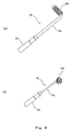
- Fig. 4(a) is a perspective view showing a defoaming roller 20 for flat planes.
- Fig. 4(b) is a perspective view showing a defoaming roller 30 for corners.
- the defoaming roller 20 includes: a rod-shaped supporting portion 20a; a roller portion 20b formed at one end of the supporting portion 20a and having a plurality of grooves extending in a circumferential direction; and a grip portion 20c formed at the other end of the supporting portion 20a
- the defoaming roller 30 includes: a rod-shaped supporting portion 30a; a roller portion 30b formed at one end of the supporting portion 30a and having a plurality of grooves extending in a circumferential direction; and a grip portion 30c formed at the other end of the supporting portion 30a.
- the roller portion 30b of the defoaming roller 30 for corners is narrower in width than the roller portion 20b of the defoaming roller 20 for flat planes.
- the surface of the roller portion 30b has a convex shape in its entirety.
- the defoaming roller 20 or 30 is used depending on applied portions. By rolling the roller portion 20b or 30b on the surface of the carbon fiber sheet 13, the carbon fiber sheet 13 is caused to spread along the wave shape of the roof board 6 and is impregnated with the impregnated adhesive resin 14 while removing the air between the roof board 6 and the carbon fiber sheet 13.
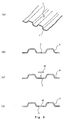
- Figs. 5(a) to 5(d) are diagrams for explaining a procedure of reinforcing a crack C of the roof board 6.
- the following will explain reinforcement in a case where the crack C is formed on a part of the roof board 6 as shown in Figs. 5(a) and 5(b) .
- a portion surrounding the crack C is removed from the roof board 6.
- a circular opening S is formed.
- the opening S is closed by a closing plate 40.
- the closing plate 40 is temporarily joined to the edge of the opening of the roof board 6 by, for example, welding two portions of the peripheral edge of the closing plate 40.
- a carbon fiber sheet is bonded to the upper surface of the closing plate 40 and the upper surface of a portion around the closing plate 40 by an impregnated adhesive resin via a primer.
- a carbon fiber reinforced resin member is formed.
- the carbon fiber sheet may be directly bonded to the crack C and the portion around the crack C by the impregnated adhesive resin without forming the opening S.
- the crack is generated but is not growing and has a linear shape, and water leakage is small in amount, it is unnecessary to remove the crack.
- the crack is growing and can be visually confirmed, and the water leakage is large in amount, it is desirable to remove the crack and then provide the closing plate.
- Fig. 6(a) is a major portion plan view showing a connection portion where the roof board 6 and an end bodyshell 50 are connected to each other.
- Fig. 6(b) is a major portion cross-sectional view thereof.
- Fig. 6(c) is a diagram of a conventional example and corresponds to Fig. 6(b) .
- spot welding W1 when joining a front end portion of the roof board 6 and an upper end portion of the end bodyshell 50 each other, these are fixed by spot welding W1, and fillet continuous welding W2 is further performed. This is because the seal performance is required. In this case, distortion of the roof board 6 by the heat affect of the fillet continuous welding W2 becomes significant.
- the front end portion of the roof board 6 is stacked on a part of the upper end portion of the end bodyshell 50, and these are joined to each other by the spot welding W1.
- a carbon fiber sheet is disposed to cover both the front end portion of the roof board 6 and the upper end portion of the end bodyshell 50 and is then bonded by the impregnated adhesive resin to both the front end portion of the roof board 6 and the upper end portion of the end bodyshell 50.
- a carbon fiber reinforced resin member 51 is formed.
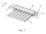
- Fig. 7 is a major portion perspective view showing a connection portion where the underframe 4 and the floor panel 9 are connected to each other.
- the floor panel 9 is a thin metal plate formed such that a cross section thereof orthogonal to the railcar longitudinal direction X has a wave shape.
- the thickness of the floor panel 9 is from 0.6 to 1.2 mm (for example, 0.6 mm).
- a rear end member 60 having an inversed concave cross section and extending in the carbody width direction is joined to the upper surface of an end beam 61 of the underframe 4.
- a range where the carbon fiber reinforced resin member 62 is provided may be a range which has a width of L2 (50 to 100 mm) and is spaced apart from the end portion (fillet welded portion) of the floor panel 9 by L1 (5 to 10 mm).
- the carbon fiber sheet 13 having flexibility is spread along a partial region of the metal roof board 6 or floor panel 9 having the wave-shaped cross section to be impregnated with and bonded by the impregnated adhesive resin 14.
- the fiber reinforced resin member 12 bonded to the roof board 6 or the like can be formed easily.
- the roof board 6 or the like can be reinforced by a simple process while reducing the carbody weight.
- the carbon fiber sheet 13 is disposed on a partial region of the roof board 6 or the like, impregnated and bonded, the manufacturing accuracy does not deteriorate by the thermal distortion, and the water-tightness does not deteriorate by the damage on the bolt hole.
- the carbon fiber sheet 13 is disposed on a partial region of the roof board 6 or the like, and the frame 5, the roof board 6, and the like that are major portions are made of metal, the cost and the recyclability can be appropriately maintained. As above, the cost, recyclability, and manufacturing efficiency of the railcar bodyshell 1 can be appropriately maintained while improving the manufacturing accuracy and water-tightness thereof and reducing the carbody weight thereof.
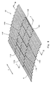
- Fig. 8 is a major portion perspective view of a roof bodyshell 102 of Embodiment 2 of the present invention.
- Fig. 9 is an enlarged view showing a part of a cross section taken along line IX-IX of Fig. 8 .
- Fig. 10 is an enlarged view showing a part of a cross section taken along line X-X of Fig. 8 .
- a plurality of carbon fiber sheets 113A to 113H each having a rectangular shape in plan view are arranged so as to spread all over the upper surface of the partial region of the roof board 6 via the primer 11 (see Fig. 9 ).
- the roof board 6 is joined to the frame 5 by the spot welding W2.
- a rear end portion 113Aa of the carbon fiber sheet 113A and a front end portion 113Ba of the carbon fiber sheet 113B is located above the frame 5, the front end portion 113Ba being adjacently located on a rear side of the rear end portion 113Aa.
- the end portions 113Aa and 113Ba opposed to each other are arranged such that a space is formed therebetween and just above a spot welded portion W2. As shown in Fig.
- a right end portion 113Ab of the carbon fiber sheet 113A and a left end portion 113Cb of the carbon fiber sheet 113C are located at the mountain portion 6a of the roof board 6, the left end portion 113Cb being adjacently located on a right side of the right end portion 113Ab.
- the end portions 113Ab and 113Cb opposed to each other are joined to each other so as to overlap each other.
- the plurality of carbon fiber sheets 113A to 113H each having a rectangular shape in plan view are arranged so as to spread all over, the size of the carbon fiber sheet handled by a worker at one time is reduced, and this improves workability.
- the end portions 113Aa and 113Ba, which are opposed to each other in the railcar longitudinal direction, of the carbon fiber sheets 113A and 113B are spaced apart from each other so as to avoid the spot welded portion W2, the adhesion of the end portions 113Aa and 113Ba is stabilized.
- end portions 113Ab and 113Cb which are adjacent to each other in the railcar width direction, of the carbon fiber sheets 113A and 113C are located at the mountain portion 6a of the roof board 6, the works of impregnating and bonding these end portions 113Ab and 113Cb are easily performed, and the adhesion between these end portions 113Ab and 113Cb is stabilized. Moreover, these end portions 113Ab and 113Cb overlap each other. Therefore, even if there are size errors among the carbon fiber sheets 113A to 113H, a desired size as the plurality of carbon fiber sheets arranged can be realized by adjusting the amount of overlap.
- the other components are the same as those in Embodiment 1, so that explanations thereof are omitted.
- Fig. 11 is a diagram of a roof bodyshell 202 of Embodiment 3 of the present invention and corresponds to Fig. 9 .
- Fig. 12 is a diagram of the roof bodyshell 202 shown in Fig. 11 and corresponds to Fig. 10 .
- carbon fiber sheets 213A to 213C and 313A to 313C are arranged such that a plurality of layers (for example, two layers) are stacked.
- a plurality of layers for example, two layers
- railcar-longitudinal end portions 313Aa and 313Ba of the carbon fiber sheets 313A and 313B as the second layers are arranged so as to be displaced by about 5 to 10mm such that a gap therebetween is larger than a gap between railcar-longitudinal end portions 213Aa and 213Ba of the carbon fiber sheets 213A and 213B as the first layers.
- the end portions of the stacked carbon fiber sheets are arranged in a step shape. Therefore, stress concentration is relieved.
- railcar-width-direction end portions 213Ab and 213Cb of the carbon fiber sheets 213A and 213C as the first layers and railcar-width-direction end portions 313Ab and 313Cb of the carbon fiber sheets 313A and 313C as the second layers are arranged at substantially the same position when viewed from above.
- the right end portions 213Ab and 313Ab of the carbon fiber sheets 213A and 313A and the left end portions 213Cb and 313Cb of the carbon fiber sheets 213C and 313C are located at the mountain portion 6a of the roof board 6, the left end portions 213Cb and 313Cb being adjacently located on a right side of the right end portion 213Ab and 313Ab, respectively.
- the right end portion 213Ab and the left end portion 213Cb opposed to each other are arranged so as not to overlap each other but to face each other, and the right end portion 313Ab and the left end portion 313Cb opposed to each other are arranged so as not to overlap each other but to face each other.
- Example of a process procedure of joining the carbon fiber reinforced resin member to the railcar bodyshell will be explained.
- the process is carried out at an ambient temperature of about 0 to 40°C.
- carbon fiber sheets, primers, and impregnated adhesive resins are prepared.
- Used as the carbon fiber sheet is a highly-elastic unidirectional material (FTS-C8-30 produced by Nippon Steel Composite Co., Ltd.).
- Properties of carbon fiber contained in the carbon fiber sheet are as follows: Tensile strength is 1,900 N/mm 2 , and tensile elasticity is 6.4 ⁇ 10 5 N/mm 2 .
- FP-NSL used as the primer is a two-liquid mixing type epoxy resin
- FR-E3PL used as the impregnated adhesive resin
- Viscosity of about 4,400 mPa ⁇ s used as the primer.
- a predetermined portion which requires reinforcement is grinded by a grinder (for example, #100) or is so-called BG#80 finish (a finish direction is the railcar longitudinal direction). Then, dirt is removed from the surface of the predetermined portion by adequately degreasing the surface by acetone.
- a grinder for example, #100
- BG#80 finish a finish direction is the railcar longitudinal direction.
- the carbon fiber sheet is cut by using cutting tools, such as a cutter knife and a ruler, into a desired shape corresponding to the predetermined portion.
- cutting tools such as a cutter knife and a ruler
- the primer is applied by using a roller brush at a ratio of, for example, 200 g/m 2 and is left for two to four hours or longer (preferably about a day).
- the purposes of applying the primer are to protect the surface of the roof board immediately after the roof board is grinded and to avoid the generation of the corrosion by a potential difference between the carbon fiber of the carbon fiber reinforced resin and the roof board directly contacting each other.
- the primer also serves as the insulating layer.
- the reason why the amount of primer applied is managed is because it is difficult to manage the thickness of the resin during the process.
- the reason why the viscosity of the primer is lower than that of the impregnated adhesive resin is because it is necessary to smoothly spread the primer on the surface of the roof board.
- the impregnated adhesive resin is applied by the roller brush as an undercoating.
- used for one layer of the impregnated adhesive resin is 500 g/m 2 .
- the carbon fiber sheet Before the undercoating is solidified, the carbon fiber sheet is attached so as to spread along the roof board by pressing the carbon fiber sheet with hands of a worker. At this time, since the viscosity of the impregnated adhesive resin is high, the carbon fiber sheet is not displaced. Then, the carbon fiber sheet is rubbed with a degassing roller and is impregnated with the impregnated adhesive resin. Then, the carbon fiber sheet is left for about 30 minutes. Thus, the impregnation proceeds by capillarity (the impregnated resin comes to the surface from between the fibers).
- the impregnated adhesive resin is applied thereto by the roller brush as an overcoating.
- used for one layer of the impregnated adhesive resin is 300 g/m 2 , which is smaller than that of the undercoating.
- used for one undercoating is 500 g/m 2
- used for one overcoating is 300 g/m 2 .
- the reason why the undercoating is larger in amount than the overcoating is because the sheet is efficiently impregnated with the resin by the capillarity so as to be held during the impregnation.
- the process returns to the step (4), and the carbon fiber sheet is attached as the second or subsequent layer.
- the amount of resin used between the sheets is determined in consideration of workability and ease of impregnation. However, the amount of resin used between the sheets can be changed in accordance with the amount of fiber per unit volume such that the fiber and the resin are contained at a substantially equal rate.
Landscapes
- Engineering & Computer Science (AREA)
- Mechanical Engineering (AREA)
- Life Sciences & Earth Sciences (AREA)
- Wood Science & Technology (AREA)
- Body Structure For Vehicles (AREA)
- Laminated Bodies (AREA)
- Standing Axle, Rod, Or Tube Structures Coupled By Welding, Adhesion, Or Deposition (AREA)
Abstract
Description
- The present invention relates to a method for reinforcing a railcar bodyshell including a wave-shaped plate and a frame and to the railcar bodyshell.
- Railcar bodyshells made of stainless steel, aluminum, or the like have been conventionally known. As a roof board of a roof bodyshell of a railcar or a floor panel of an underframe of the railcar, a corrugated panel (hereinafter referred to as a "thin wavy plate") which has a wave-shaped cross section and is small in thickness is used to reduce the weight of the railcar while maintaining the strength thereof. Conventionally, weak portions of the roof bodyshell and underframe of the railcar have been reinforced by, for example, welding of reinforcing plates so as to be increased in stiffness. However, in a case where the weak portion to be reinforced is a part of the thin wavy plate, it is difficult to join a reinforcing member to the weak portion by welding or bolts. For example, in the case of the welding, one problem is that manufacturing accuracy deteriorates by thermal distortion, and in the case of the bolts, another problem is that a bolt hole is damaged and this deteriorates seal performance (hereinafter referred to as "water-tightness") for preventing the ingress of water. Further, yet another problem is that the weights of the roof board and the floor panel increase by reinforcement.
- Here, each of PTLs 1 to 4 proposes a technique to use a carbon fiber reinforced resin for the outside plate and frame member of the railcar. In accordance with these techniques, the railcar bodyshell can be significantly reduced in weight.
-
- PTL 1: Japanese Laid-Open Patent Application Publication No.
5-213189 - PTL 2: Japanese Laid-Open Patent Application Publication No.
6-263029 - PTL 3: Japanese Laid-Open Patent Application Publication No.
7-81556 - PTL 4: Japanese Patent No.
3219278 - However, in accordance with these techniques, since major portions of the railcar bodyshell are formed by the carbon fiber reinforced resin, a use ratio of the carbon fiber reinforced resin in the bodyshell is high. Compared to metals, the cost of the carbon fiber reinforced resin is high, and it is difficult to recycle the carbon fiber reinforced resin. Therefore, the problem is that in a case where the railcar bodyshell includes the major portions formed by the carbon fiber reinforced resin, the cost thereof significantly increases and the recyclability thereof deteriorates. On this account, in consideration of the cost and the recyclability, the thin wavy plate made of a metal, such as stainless steel, is used for the bodyshell. However, currently, the weak portion of the thin wavy plate cannot be appropriately reinforced. Moreover, in a case where a component formed by the carbon fiber reinforced resin has a three-dimensional shape, a step of forming the carbon fiber reinforced resin into a predetermined shape is required, and this deteriorates manufacturing efficiency.
- Here, an object of the present invention is to appropriately maintaining the cost, recyclability, and manufacturing efficiency of the railcar bodyshell while improving the manufacturing accuracy and water-tightness thereof and reducing the carbody weight thereof.
- A railcar bodyshell reinforcing method of the present invention includes the steps of: in a bodyshell including a metal frame and a metal plate joined to the frame and formed such that a cross section thereof orthogonal to a railcar longitudinal direction has a wave shape, disposing a fiber sheet on at least a part of the plate; and forming a fiber reinforced resin member by bonding the fiber sheet to the part of the plate by an impregnated adhesive resin. Here, the "fiber sheet" is a sheet which is formed such that fibers, such as carbon fibers, utilized in a fiber reinforced resin are formed like a cloth and which is not impregnated with a resin.
- In accordance with the above method, the fiber sheet having flexibility is spread on a part of the metal plate having a wave-shaped cross section and is impregnated with and bonded by the impregnated adhesive resin. With this, the fiber reinforced resin member bonded to the plate can be easily formed, and the bodyshell can be reinforced by a simple process while reducing the carbody weight thereof. Moreover, since the fiber sheet is disposed on a part of the plate, impregnated and bonded, the manufacturing accuracy does not deteriorate by the thermal distortion, and the water-tightness does not deteriorate by the damage on the bolt hole. In addition, since the fiber sheet is disposed on a part of the plate, and the frame and plate that are major portions are made of metal, the cost and the recyclability can be appropriately maintained. As above, the cost, recyclability, and manufacturing efficiency of the railcar bodyshell can be appropriately maintained while improving the manufacturing accuracy and water-tightness thereof and reducing the carbody weight thereof.
- Moreover, a railcar bodyshell of the present invention includes: a metal frame; a metal plate joined to the frame and formed such that a cross section thereof orthogonal to a railcar longitudinal direction has a wave shape; and a fiber reinforced resin member joined to a part of the plate and reinforcing the plate.
- In accordance with the above configuration, as with the above, the cost, recyclability, and manufacturing efficiency can be appropriately maintained while improving the manufacturing accuracy and water-tightness and reducing the carbody weight.
- In accordance with the present invention, the cost, recyclability, and manufacturing efficiency of the railcar bodyshell can be appropriately maintained while improving the manufacturing accuracy and water-tightness thereof and reducing the carbody weight thereof.
-
- [
Fig. 1] Fig. 1 is a perspective view showing a part of a railcar bodyshell of Embodiment 1 of the present invention. - [
Fig. 2] Fig. 2 is a major portion perspective view of a roof bodyshell shown inFig. 1 . - [
Fig. 3] Fig. 3 is an enlarged view showing a part of a cross section taken along line III-III ofFig. 2 . - [
Figs. 4] Fig. 4(a) is a perspective view showing a defoaming roller for flat planes, andFig. 4(b) is a perspective view showing a defoaming roller for corners. - [
Figs. 5] Figs. 5(a) to 5(d) are diagrams for explaining a procedure of reinforcing a crack on a roof board shown inFig. 1 . - [
Figs. 6] Fig. 6(a) is a major portion plan view showing a connection portion where the roof board ofFig. 1 and an end bodyshell are connected to each other.Fig. 6(b) is a major portion cross-sectional view thereof.Fig. 6(c) is a diagram of a conventional example and corresponds toFig. 6(b) . - [
Fig. 7] Fig. 7 is a major portion perspective view showing a connection portion where the underframe ofFig. 1 and a floor panel are connected to each other. - [
Fig. 8] Fig. 8 is a major portion perspective view of the roof bodyshell ofEmbodiment 2 of the present invention. - [
Fig. 9] Fig. 9 is an enlarged view showing a part of a cross section taken along line IX-IX ofFig. 8 . - [
Fig. 10] Fig. 10 is an enlarged view showing a part of a cross section taken along line X-X ofFig. 8 . - [
Fig. 11] Fig. 11 is a diagram of the roof bodyshell ofEmbodiment 3 of the present invention and corresponds toFig. 9 . - [
Fig. 12] Fig. 12 is a diagram of the roof bodyshell ofFig. 11 and corresponds toFig. 10 . - Hereinafter, embodiments of the present invention will be explained in reference to the drawings.
-
Fig. 1 is a perspective view showing a part of a railcar bodyshell 1 of Embodiment 1 of the present invention. As shown inFig. 1 , the railcar bodyshell 1 includes aroof bodyshell 2,side bodyshells 3, end bodyshells (not shown), and anunderframe 4. Theroof bodyshell 2 includes ametal frame 5 and ametal roof board 6 joined to the upper surface of theframe 5. Theframe 5 includes purlines and carlines. Each of theside bodyshells 3 include a metal side outside plate 7 and a plurality of metal frame members 8 joined to the inner surface of the side outside plate 7. The side outside plate 7 constitutes a side wall. Moreover, ametal floor panel 9 is joined to themetal underframe 4. The metal used for these members may be stainless steel, aluminum, or the like. -
Fig. 2 is a major portion perspective view of theroof bodyshell 2.Fig. 3 is an enlarged view showing a part of a cross section taken along line III-III ofFig. 2 . As shown inFigs. 2 and 3 , theroof board 6 is a thin corrugated panel formed such thatmountain portions 6a andvalley portions 6b extending in a railcar longitudinal direction X are alternately arranged in a railcar width direction. A cross section of theroof board 6 has a wave shape, the cross section being orthogonal to the railcar longitudinal direction X. Theroof board 6 is smaller in thickness than the side outside plate 7 of theside bodyshell 3. The thickness of theroof board 6 is from 0.5 to 1.0 mm (for example, 0.6 mm). A carbon fiber reinforcedresin member 12 is provided on theroof board 6 of the present embodiment to reinforce a partial region (for example, a center portion in the railcar longitudinal direction X) of theroof board 6. The carbon fiber reinforcedresin member 12 is larger in thickness than theroof board 6. - A specific procedure of joining the carbon fiber reinforced
resin member 12 is as follows. A reinforcement target portion on the upper surface of theroof board 6 is degreased. A primer 11 (for example, an epoxy resin) made of an impregnated adhesive resin is applied to this target portion and is then left. After theprimer 11 is solidified with time, an impregnated adhesive resin 14 (for example, an epoxy resin) is applied as an undercoating onto theprimer 11. Before the undercoating is solidified, a resin non-impregnatedcarbon fiber sheet 13 is stacked on the undercoating. At this time, thecarbon fiber sheet 13 is spread along the wave shape of theroof board 6 such that a fiber direction thereof is substantially parallel to the railcar longitudinal direction X. Next, the impregnatedadhesive resin 14 is applied to thecarbon fiber sheet 13. By using, for example,defoaming rollers 20 and 30 (seeFig. 4 ), the impregnatedadhesive resin 14 is infiltrated into thecarbon fiber sheet 13, and the surface of thecarbon fiber sheet 13 is flattened. The impregnatedadhesive resin 14 is left to be solidified with time. Thus, the carbon fiber reinforcedresin member 12 bonded to theroof board 6 is formed. With this, the carbon fiber reinforcedresin member 12 achieves an effect of reinforcing a predetermined portion of thethin roof board 6. If a local recess 6c exists on the reinforcement target portion of theroof board 6, the recess 6c may be filled with putty 15, the surface of the putty 15 may be processed to be flush with the surface of its adjacent portion, and theprimer 11 may be then applied thereto. However, if the curvature of the recess 6c is small, theprimer 11 may be directly applied without filling the recess 6c with the putty 15. Moreover, thecarbon fiber sheet 13 may be constituted by one layer or a plurality of layers. -
Fig. 4(a) is a perspective view showing adefoaming roller 20 for flat planes.Fig. 4(b) is a perspective view showing adefoaming roller 30 for corners. As shown inFigs. 4(a) and 4(b) , thedefoaming roller 20 includes: a rod-shaped supportingportion 20a; aroller portion 20b formed at one end of the supportingportion 20a and having a plurality of grooves extending in a circumferential direction; and agrip portion 20c formed at the other end of the supportingportion 20a, and thedefoaming roller 30 includes: a rod-shaped supportingportion 30a; aroller portion 30b formed at one end of the supportingportion 30a and having a plurality of grooves extending in a circumferential direction; and agrip portion 30c formed at the other end of the supportingportion 30a. Theroller portion 30b of thedefoaming roller 30 for corners is narrower in width than theroller portion 20b of thedefoaming roller 20 for flat planes. When viewed from a direction orthogonal to a rotation axis line of theroller portion 30b, the surface of theroller portion 30b has a convex shape in its entirety. Thedefoaming roller roller portion carbon fiber sheet 13, thecarbon fiber sheet 13 is caused to spread along the wave shape of theroof board 6 and is impregnated with the impregnatedadhesive resin 14 while removing the air between theroof board 6 and thecarbon fiber sheet 13. -
Figs. 5(a) to 5(d) are diagrams for explaining a procedure of reinforcing a crack C of theroof board 6. The following will explain reinforcement in a case where the crack C is formed on a part of theroof board 6 as shown inFigs. 5(a) and 5(b) . In this case, as shown inFig. 5(c) , a portion surrounding the crack C is removed from theroof board 6. Thus, a circular opening S is formed. Next, as shown inFig. 5(d) , the opening S is closed by aclosing plate 40. At this time, the closingplate 40 is temporarily joined to the edge of the opening of theroof board 6 by, for example, welding two portions of the peripheral edge of theclosing plate 40. Then, a carbon fiber sheet is bonded to the upper surface of theclosing plate 40 and the upper surface of a portion around the closingplate 40 by an impregnated adhesive resin via a primer. Thus, a carbon fiber reinforced resin member is formed. Depending on the status of the crack C, the carbon fiber sheet may be directly bonded to the crack C and the portion around the crack C by the impregnated adhesive resin without forming the opening S. For example, in a case where the crack is generated but is not growing and has a linear shape, and water leakage is small in amount, it is unnecessary to remove the crack. In contrast, in a case where the crack is growing and can be visually confirmed, and the water leakage is large in amount, it is desirable to remove the crack and then provide the closing plate. -
Fig. 6(a) is a major portion plan view showing a connection portion where theroof board 6 and anend bodyshell 50 are connected to each other.Fig. 6(b) is a major portion cross-sectional view thereof.Fig. 6(c) is a diagram of a conventional example and corresponds toFig. 6(b) . As shown inFig. 6(c) , in the conventional example, when joining a front end portion of theroof board 6 and an upper end portion of theend bodyshell 50 each other, these are fixed by spot welding W1, and fillet continuous welding W2 is further performed. This is because the seal performance is required. In this case, distortion of theroof board 6 by the heat affect of the fillet continuous welding W2 becomes significant. Here, as shown inFigs. 6(a) and 6(b) , the front end portion of theroof board 6 is stacked on a part of the upper end portion of theend bodyshell 50, and these are joined to each other by the spot welding W1. Then, a carbon fiber sheet is disposed to cover both the front end portion of theroof board 6 and the upper end portion of theend bodyshell 50 and is then bonded by the impregnated adhesive resin to both the front end portion of theroof board 6 and the upper end portion of theend bodyshell 50. Thus, a carbon fiber reinforcedresin member 51 is formed. With this, the distortion of theroof board 6 by the heat affect of the fillet continuous welding does not occur, the seal performance can be secured, and the end portion of theroof board 6 can be reinforced. -
Fig. 7 is a major portion perspective view showing a connection portion where theunderframe 4 and thefloor panel 9 are connected to each other. As shown inFig. 7 , thefloor panel 9 is a thin metal plate formed such that a cross section thereof orthogonal to the railcar longitudinal direction X has a wave shape. The thickness of thefloor panel 9 is from 0.6 to 1.2 mm (for example, 0.6 mm). Arear end member 60 having an inversed concave cross section and extending in the carbody width direction is joined to the upper surface of anend beam 61 of theunderframe 4. Before the end portion of thefloor panel 9 is fillet welded to a side surface of therear end member 60, the carbon fiber sheet is bonded to the end portion of thefloor panel 9 in advance via the primer by the impregnated adhesive resin. Thus, a carbon fiber reinforcedresin member 62 is formed. With this, the stiffness of thefloor panel 9 increases, and the shape thereof is stabilized. Then, the end portion of thefloor panel 9 is fillet welded to the side surface of therear end member 60. With this, since the shape of thefloor panel 9 is stabilized by the carbon fiber reinforcedresin member 62, the distortion by the heat affect is suppressed. A range where the carbon fiber reinforcedresin member 62 is provided may be a range which has a width of L2 (50 to 100 mm) and is spaced apart from the end portion (fillet welded portion) of thefloor panel 9 by L1 (5 to 10 mm). - As explained above, the
carbon fiber sheet 13 having flexibility is spread along a partial region of themetal roof board 6 orfloor panel 9 having the wave-shaped cross section to be impregnated with and bonded by the impregnatedadhesive resin 14. With this, the fiber reinforcedresin member 12 bonded to theroof board 6 or the like can be formed easily. Moreover, theroof board 6 or the like can be reinforced by a simple process while reducing the carbody weight. In addition, since thecarbon fiber sheet 13 is disposed on a partial region of theroof board 6 or the like, impregnated and bonded, the manufacturing accuracy does not deteriorate by the thermal distortion, and the water-tightness does not deteriorate by the damage on the bolt hole. Further, since thecarbon fiber sheet 13 is disposed on a partial region of theroof board 6 or the like, and theframe 5, theroof board 6, and the like that are major portions are made of metal, the cost and the recyclability can be appropriately maintained. As above, the cost, recyclability, and manufacturing efficiency of the railcar bodyshell 1 can be appropriately maintained while improving the manufacturing accuracy and water-tightness thereof and reducing the carbody weight thereof. -
Fig. 8 is a major portion perspective view of aroof bodyshell 102 ofEmbodiment 2 of the present invention.Fig. 9 is an enlarged view showing a part of a cross section taken along line IX-IX ofFig. 8 .Fig. 10 is an enlarged view showing a part of a cross section taken along line X-X ofFig. 8 . As shown inFig. 8 , in theroof bodyshell 102 of the present embodiment, a plurality ofcarbon fiber sheets 113A to 113H each having a rectangular shape in plan view are arranged so as to spread all over the upper surface of the partial region of theroof board 6 via the primer 11 (seeFig. 9 ). Since a procedure of forming the carbon fiber reinforced resin member by bonding thesecarbon fiber sheets 113A to 113H to the partial region of theroof board 6 by the impregnated adhesive resin is the same as that in Embodiment 1, a detailed explanation thereof is omitted herein. - As shown in
Fig. 9 , theroof board 6 is joined to theframe 5 by the spot welding W2. A rear end portion 113Aa of thecarbon fiber sheet 113A and a front end portion 113Ba of thecarbon fiber sheet 113B is located above theframe 5, the front end portion 113Ba being adjacently located on a rear side of the rear end portion 113Aa. The end portions 113Aa and 113Ba opposed to each other are arranged such that a space is formed therebetween and just above a spot welded portion W2. As shown inFig. 10 , a right end portion 113Ab of thecarbon fiber sheet 113A and a left end portion 113Cb of thecarbon fiber sheet 113C are located at themountain portion 6a of theroof board 6, the left end portion 113Cb being adjacently located on a right side of the right end portion 113Ab. The end portions 113Ab and 113Cb opposed to each other are joined to each other so as to overlap each other. - As explained above, since the plurality of
carbon fiber sheets 113A to 113H each having a rectangular shape in plan view are arranged so as to spread all over, the size of the carbon fiber sheet handled by a worker at one time is reduced, and this improves workability. Moreover, since the end portions 113Aa and 113Ba, which are opposed to each other in the railcar longitudinal direction, of thecarbon fiber sheets carbon fiber sheets mountain portion 6a of theroof board 6, the works of impregnating and bonding these end portions 113Ab and 113Cb are easily performed, and the adhesion between these end portions 113Ab and 113Cb is stabilized. Moreover, these end portions 113Ab and 113Cb overlap each other. Therefore, even if there are size errors among thecarbon fiber sheets 113A to 113H, a desired size as the plurality of carbon fiber sheets arranged can be realized by adjusting the amount of overlap. The other components are the same as those in Embodiment 1, so that explanations thereof are omitted. -
Fig. 11 is a diagram of aroof bodyshell 202 ofEmbodiment 3 of the present invention and corresponds toFig. 9 .Fig. 12 is a diagram of theroof bodyshell 202 shown inFig. 11 and corresponds toFig. 10 . As shown inFigs. 11 and 12 , in theroof bodyshell 202 of the present embodiment,carbon fiber sheets 213A to 213C and 313A to 313C are arranged such that a plurality of layers (for example, two layers) are stacked. As shown inFig. 11 , railcar-longitudinal end portions 313Aa and 313Ba of thecarbon fiber sheets carbon fiber sheets - As shown in
Fig. 12 , railcar-width-direction end portions 213Ab and 213Cb of thecarbon fiber sheets carbon fiber sheets carbon fiber sheets carbon fiber sheets mountain portion 6a of theroof board 6, the left end portions 213Cb and 313Cb being adjacently located on a right side of the right end portion 213Ab and 313Ab, respectively. The right end portion 213Ab and the left end portion 213Cb opposed to each other are arranged so as not to overlap each other but to face each other, and the right end portion 313Ab and the left end portion 313Cb opposed to each other are arranged so as not to overlap each other but to face each other. - As explained above, by stacking a plurality of
carbon fiber sheets 213A to 213C and 313A to 313C, desired strength and stiffness can be given to theroof board 6 or the like. The other components are the same as those in Embodiment 1, so that explanations thereof are omitted. - Hereinafter, Example of a process procedure of joining the carbon fiber reinforced resin member to the railcar bodyshell will be explained. The process is carried out at an ambient temperature of about 0 to 40°C. First, carbon fiber sheets, primers, and impregnated adhesive resins are prepared. Used as the carbon fiber sheet is a highly-elastic unidirectional material (FTS-C8-30 produced by Nippon Steel Composite Co., Ltd.). Properties of carbon fiber contained in the carbon fiber sheet are as follows: Tensile strength is 1,900 N/mm2, and tensile elasticity is 6.4×10⁵ N/mm2. Used as the primer is a two-liquid mixing type epoxy resin (FP-NSL produced by Nippon Steel Materials Co., Ltd, Composites Company.: Viscosity of about 1,000 mPa.s). Used as the impregnated adhesive resin is a two-liquid mixing type epoxy resin (FR-E3PL produced by Nippon Steel Materials Co., Ltd, Composites Company.: Viscosity of about 4,400 mPa·s). Steps (1) to (7) below are carried out in order.
- A predetermined portion which requires reinforcement is grinded by a grinder (for example, #100) or is so-called BG#80 finish (a finish direction is the railcar longitudinal direction). Then, dirt is removed from the surface of the predetermined portion by adequately degreasing the surface by acetone.
- The carbon fiber sheet is cut by using cutting tools, such as a cutter knife and a ruler, into a desired shape corresponding to the predetermined portion.
- The primer is applied by using a roller brush at a ratio of, for example, 200 g/m2 and is left for two to four hours or longer (preferably about a day). Here, the purposes of applying the primer are to protect the surface of the roof board immediately after the roof board is grinded and to avoid the generation of the corrosion by a potential difference between the carbon fiber of the carbon fiber reinforced resin and the roof board directly contacting each other. To be specific, the primer also serves as the insulating layer. Moreover, the reason why the amount of primer applied is managed is because it is difficult to manage the thickness of the resin during the process. Moreover, the reason why the viscosity of the primer is lower than that of the impregnated adhesive resin is because it is necessary to smoothly spread the primer on the surface of the roof board.
- The impregnated adhesive resin is applied by the roller brush as an undercoating. For example, used for one layer of the impregnated adhesive resin is 500 g/m2. Here, the impregnated adhesive resin is prepared such that a main agent and a hardening agent are measured and mixed at a predetermined mixing ratio (Main Agent : Hardening Agent = 2 : 1), and then uniformly kneaded by a spatula.
- Before the undercoating is solidified, the carbon fiber sheet is attached so as to spread along the roof board by pressing the carbon fiber sheet with hands of a worker. At this time, since the viscosity of the impregnated adhesive resin is high, the carbon fiber sheet is not displaced. Then, the carbon fiber sheet is rubbed with a degassing roller and is impregnated with the impregnated adhesive resin. Then, the carbon fiber sheet is left for about 30 minutes. Thus, the impregnation proceeds by capillarity (the impregnated resin comes to the surface from between the fibers).
- Further, the impregnated adhesive resin is applied thereto by the roller brush as an overcoating. For example, used for one layer of the impregnated adhesive resin is 300 g/m2, which is smaller than that of the undercoating. Here, used for one undercoating is 500 g/m2, and used for one overcoating is 300 g/m2. The reason why the undercoating is larger in amount than the overcoating is because the sheet is efficiently impregnated with the resin by the capillarity so as to be held during the impregnation.
- According to need, the process returns to the step (4), and the carbon fiber sheet is attached as the second or subsequent layer. The amount of resin used between the sheets is determined in consideration of workability and ease of impregnation. However, the amount of resin used between the sheets can be changed in accordance with the amount of fiber per unit volume such that the fiber and the resin are contained at a substantially equal rate.
-
- 1
- railcar bodyshell
- 2
- roof bodyshell
- 3
- side bodyshell
- 4
- underframe
- 5
- frame
- 6
- roof board
- 9
- floor panel
- 11
- primer
- 12
- carbon fiber reinforced resin member
- 13, 113A to 113H, 213A to 213C, 313A to 313C
- carbon fiber sheet
- 14
- impregnated adhesive resin
Claims (10)
- A method for reinforcing a railcar bodyshell, comprising the steps of:in a bodyshell including a metal frame and a metal plate joined to the frame and formed such that a cross section thereof orthogonal to a railcar longitudinal direction has a wave shape, disposing a fiber sheet on at least a part of the plate; andforming a fiber reinforced resin member by bonding the fiber sheet to the part of the plate by an impregnated adhesive resin.
- The method according to claim 1, wherein the step of disposing the fiber sheet includes disposing the fiber sheet such that the fiber sheet spreads along the wave shape of the plate.
- The method according to claim 1, wherein the step of forming the fiber reinforced resin member includes: degreasing the part of the plate; applying a primer; after the primer is solidified, applying the impregnated adhesive resin as an undercoating; before the impregnated adhesive resin as the undercoating is solidified, stacking the fiber sheet thereon; further applying the impregnated adhesive resin as an overcoating; and infiltrating the impregnated adhesive resin into the fiber sheet.
- The method according to claim 1, wherein before the step of disposing the fiber sheet, putty is applied to a recess or crack on the part of the plate such that a surface of the putty becomes flush with a surface of a portion adjacent to the putty applied.
- The method according to claim 1, wherein:before the step of disposing the fiber sheet, an opening is formed by removing a portion surrounding a crack on the part of the plate, and the opening is closed by a closing plate; andin the step of disposing the fiber sheet, the fiber sheet is disposed so as to cover the closing plate and a portion around the closing plate.
- The method according to claim 1, wherein in the step of disposing the fiber sheet, a plurality of fiber sheets are disposed so as to spread all over the part of the plate.
- The method according to claim 6, wherein:each of the plurality of fiber sheets has a rectangular shape in plan view; andin the step of disposing the fiber sheet, opposing end portions of adjacent fiber sheets among the plurality of fiber sheets are located at a mountain portion of the wave shape of the plate.
- The method according to claim 1, wherein in the step of disposing the fiber sheet, the fiber sheet is disposed such that a fiber direction thereof coincides with the railcar longitudinal direction.
- The method according to claim 1, wherein:the plate is a roof board;in the step of disposing the fiber sheet, the fiber sheet is disposed so as to cover both a front end portion of the roof board and an upper end portion of an end bodyshell, the front end portion of the roof board overlapping and being joined to a part of the upper end portion of the end bodyshell; andin the step of forming the fiber reinforced resin member, the fiber sheet is bonded by an impregnated adhesive resin to both the front end portion of the roof board and the upper end portion of the end bodyshell.
- A railcar bodyshell comprising:a metal frame;a metal plate joined to the frame and formed such that a cross section thereof orthogonal to a railcar longitudinal direction has a wave shape; anda fiber reinforced resin member joined to a part of the plate and reinforcing the plate.
Applications Claiming Priority (2)
| Application Number | Priority Date | Filing Date | Title |
|---|---|---|---|
| JP2009138844 | 2009-06-10 | ||
| PCT/JP2010/003521 WO2010143365A1 (en) | 2009-06-10 | 2010-05-26 | Method for reinforcing structure for railway rolling stock and structure for railway rolling stock |
Publications (2)
| Publication Number | Publication Date |
|---|---|
| EP2441640A1 true EP2441640A1 (en) | 2012-04-18 |
| EP2441640A4 EP2441640A4 (en) | 2013-09-04 |
Family
ID=43308628
Family Applications (1)
| Application Number | Title | Priority Date | Filing Date |
|---|---|---|---|
| EP10785897.9A Withdrawn EP2441640A4 (en) | 2009-06-10 | 2010-05-26 | METHOD FOR STRUCTURAL REINFORCEMENT FOR RAILWAY ROLLING EQUIPMENT AND STRUCTURE FOR RAILWAY ROLLING EQUIPMENT |
Country Status (6)
| Country | Link |
|---|---|
| US (1) | US8464643B2 (en) |
| EP (1) | EP2441640A4 (en) |
| JP (1) | JP5271358B2 (en) |
| CN (1) | CN102066178B (en) |
| TW (1) | TWI409184B (en) |
| WO (1) | WO2010143365A1 (en) |
Cited By (2)
| Publication number | Priority date | Publication date | Assignee | Title |
|---|---|---|---|---|
| EP2873579A4 (en) * | 2012-07-12 | 2016-04-27 | Kawasaki Heavy Ind Ltd | RAILWAY VEHICLE |
| FR3116786A1 (en) * | 2020-12-02 | 2022-06-03 | Speedinnov | Car for railway vehicle with roof fairing |
Families Citing this family (16)
| Publication number | Priority date | Publication date | Assignee | Title |
|---|---|---|---|---|
| TWI395683B (en) * | 2009-03-30 | 2013-05-11 | Kawasaki Heavy Ind Ltd | Railway vehicle structure and manufacturing method thereof |
| EP2441640A4 (en) * | 2009-06-10 | 2013-09-04 | Kawasaki Heavy Ind Ltd | METHOD FOR STRUCTURAL REINFORCEMENT FOR RAILWAY ROLLING EQUIPMENT AND STRUCTURE FOR RAILWAY ROLLING EQUIPMENT |
| WO2011142208A1 (en) * | 2010-05-10 | 2011-11-17 | 日本車輌製造株式会社 | Railroad vehicle |
| US8707872B2 (en) * | 2010-05-10 | 2014-04-29 | Nippon Sharyo, Ltd. | Railway vehicle |
| WO2011142206A1 (en) * | 2010-05-10 | 2011-11-17 | 日本車輌製造株式会社 | Railway vehicle |
| JP2012020592A (en) * | 2010-07-12 | 2012-02-02 | Kawasaki Heavy Ind Ltd | Frame structure of railway vehicle |
| CN102180196B (en) * | 2011-03-15 | 2012-09-26 | 东风汽车公司 | Method and structure for preventing impact on weak part of vehicle body shell based on light weight of vehicle body shell |
| KR101595923B1 (en) * | 2012-02-23 | 2016-02-26 | 카와사키 주코교 카부시키 카이샤 | Railroad vehicle provided with low roof structure |
| DE102012214166A1 (en) * | 2012-08-09 | 2014-03-06 | Siemens Aktiengesellschaft | Window profile for a rail vehicle |
| CN102943797A (en) * | 2012-08-23 | 2013-02-27 | 长春轨道客车股份有限公司 | Method for bonding side wall plates of vehicle body of low floor vehicle |
| US9393761B2 (en) * | 2013-03-15 | 2016-07-19 | The Boeing Company | Hybrid structure and methods for forming the same |
| FR3024117B1 (en) * | 2014-07-22 | 2018-03-30 | Alstom Transport Technologies | STRUCTURAL WALLS FOR A RAILWAY VEHICLE FUND, ASSEMBLY METHOD AND RAILWAY VEHICLE THEREFOR |
| CN106114538B (en) * | 2016-08-19 | 2018-07-24 | 中车株洲电力机车研究所有限公司 | A kind of adhering method of low-floor rail vehicle outer plaque |
| CN110281963A (en) * | 2019-06-21 | 2019-09-27 | 中车青岛四方机车车辆股份有限公司 | A body structure of a rail vehicle |
| CN110281962B (en) * | 2019-06-21 | 2020-10-02 | 中车青岛四方机车车辆股份有限公司 | A body structure of a rail vehicle |
| JP2025087283A (en) * | 2023-11-29 | 2025-06-10 | 株式会社日立製作所 | Rail vehicles |
Family Cites Families (33)
| Publication number | Priority date | Publication date | Assignee | Title |
|---|---|---|---|---|
| US2619045A (en) * | 1948-07-14 | 1952-11-25 | Budd Co | Body for land vehicles, especially railway cars, and method of its assembly |
| US3046179A (en) * | 1957-12-13 | 1962-07-24 | Gen Motors Corp | Trim panel joint covering |
| JPS598431B2 (en) * | 1981-08-14 | 1984-02-24 | 株式会社 宝建材製作所 | Coating film construction method for railway vehicle roofs |
| JPS5873068U (en) * | 1981-11-11 | 1983-05-17 | 日本車輌製造株式会社 | Railway vehicle body exterior structure |
| JPS58185360A (en) * | 1982-04-26 | 1983-10-29 | 株式会社日立製作所 | Manufacture of car structure |
| DE3838686C2 (en) * | 1988-11-15 | 1993-10-21 | Man Ghh Schienenverkehr | Vehicle compartment |
| US5433151A (en) * | 1990-09-07 | 1995-07-18 | Hitachi, Ltd. | Railway car body structures and methods of making them using welded honeycomb panels connected in an edge to edge relation |
| AU655250B2 (en) * | 1991-04-26 | 1994-12-08 | Hitachi Limited | Vehicle and method of producing the same |
| JPH05213189A (en) | 1992-02-04 | 1993-08-24 | Railway Technical Res Inst | Vehicle body structure |
| JP2692505B2 (en) | 1992-08-21 | 1997-12-17 | 株式会社日立製作所 | Vehicle repair method and vehicle |
| JPH06263029A (en) | 1993-03-11 | 1994-09-20 | Railway Technical Res Inst | Vehicle structural body |
| JPH0781556A (en) | 1993-09-10 | 1995-03-28 | Hitachi Ltd | Railway car body |
| EP0687611B1 (en) * | 1994-06-14 | 2000-01-05 | Inventio Ag | Method for the manufacturing of vehicle structures |
| US5765485A (en) * | 1995-07-21 | 1998-06-16 | Trinity Industries, Inc. | Insulated composite railway boxcar and method |
| BR9611106A (en) | 1995-10-18 | 1999-07-13 | Waggonfabrik Talbot Gmbh & Co | Modular element and assembly process |
| US6196136B1 (en) * | 1996-06-19 | 2001-03-06 | Hitachi, Ltd. | Car and side structure for car and method of manufacturing the same |
| JP3799119B2 (en) | 1997-03-04 | 2006-07-19 | 清水建設株式会社 | Structure reinforcement method |
| US6233892B1 (en) * | 1997-10-25 | 2001-05-22 | The Namlyt Company | Structural panel system |
| DE60034041D1 (en) * | 1999-06-29 | 2007-05-03 | Dofasco Inc | WALL FOR TRUCKS |
| US6871600B2 (en) * | 2001-02-09 | 2005-03-29 | Trn Business Trust | Pultruded panel |
| JP2003314085A (en) | 2002-04-19 | 2003-11-06 | Chugoku Koatsu Concrete Kogyo Kk | Repair method of concrete telegraph pole |
| US6554348B1 (en) * | 2002-06-04 | 2003-04-29 | Dan H. Gernstein | Bus body |
| JP4072908B2 (en) * | 2003-08-28 | 2008-04-09 | 川崎重工業株式会社 | Repair method of steel structure |
| WO2005113311A1 (en) * | 2004-05-13 | 2005-12-01 | Gunderson, Inc. | Air flow direction in a temperature-controlled railroad freight car |
| KR100850099B1 (en) * | 2004-05-18 | 2008-08-04 | 카와사키 주코교 카부시키 카이샤 | Structure for rolling stock |
| JP4804104B2 (en) | 2005-10-21 | 2011-11-02 | 川崎重工業株式会社 | Railway vehicle side structure and manufacturing method thereof |
| FR2901763B1 (en) * | 2006-06-02 | 2014-08-08 | Alstom Transport Sa | STRUCTURAL ASSEMBLY OF END OF RAIL VEHICLE CAR CASE. |
| FR2901764B1 (en) * | 2006-06-02 | 2019-08-09 | Alstom Transport Technologies | LATERAL SIDE OF RAILWAY VEHICLE BODY. |
| JP4857032B2 (en) | 2006-06-15 | 2012-01-18 | 川崎重工業株式会社 | Steel structure reinforcing method and reinforcing structure |
| JP2009024466A (en) * | 2007-07-24 | 2009-02-05 | Toray Ind Inc | Weld reinforcement method |
| JP2009046931A (en) | 2007-08-22 | 2009-03-05 | Nippon Oil Corp | Method for repairing steel material with carbon fiber reinforced resin plate, and repaired steel material |
| TWI395683B (en) * | 2009-03-30 | 2013-05-11 | Kawasaki Heavy Ind Ltd | Railway vehicle structure and manufacturing method thereof |
| EP2441640A4 (en) * | 2009-06-10 | 2013-09-04 | Kawasaki Heavy Ind Ltd | METHOD FOR STRUCTURAL REINFORCEMENT FOR RAILWAY ROLLING EQUIPMENT AND STRUCTURE FOR RAILWAY ROLLING EQUIPMENT |
-
2010
- 2010-05-26 EP EP10785897.9A patent/EP2441640A4/en not_active Withdrawn
- 2010-05-26 CN CN201080001846.7A patent/CN102066178B/en not_active Expired - Fee Related
- 2010-05-26 US US13/266,321 patent/US8464643B2/en not_active Expired - Fee Related
- 2010-05-26 JP JP2010537067A patent/JP5271358B2/en not_active Expired - Fee Related
- 2010-05-26 WO PCT/JP2010/003521 patent/WO2010143365A1/en not_active Ceased
- 2010-05-28 TW TW099117171A patent/TWI409184B/en not_active IP Right Cessation
Cited By (3)
| Publication number | Priority date | Publication date | Assignee | Title |
|---|---|---|---|---|
| EP2873579A4 (en) * | 2012-07-12 | 2016-04-27 | Kawasaki Heavy Ind Ltd | RAILWAY VEHICLE |
| FR3116786A1 (en) * | 2020-12-02 | 2022-06-03 | Speedinnov | Car for railway vehicle with roof fairing |
| EP4008596A1 (en) * | 2020-12-02 | 2022-06-08 | SpeedInnov | Car for railway vehicle with roof fairing |
Also Published As
| Publication number | Publication date |
|---|---|
| TW201103791A (en) | 2011-02-01 |
| US8464643B2 (en) | 2013-06-18 |
| HK1154370A1 (en) | 2012-04-20 |
| US20120067247A1 (en) | 2012-03-22 |
| JPWO2010143365A1 (en) | 2012-11-22 |
| CN102066178A (en) | 2011-05-18 |
| CN102066178B (en) | 2016-01-13 |
| EP2441640A4 (en) | 2013-09-04 |
| JP5271358B2 (en) | 2013-08-21 |
| TWI409184B (en) | 2013-09-21 |
| WO2010143365A1 (en) | 2010-12-16 |
Similar Documents
| Publication | Publication Date | Title |
|---|---|---|
| US8464643B2 (en) | Railcar bodyshell reinforcing method and railcar bodyshell | |
| US8424462B2 (en) | Railcar bodyshell and method for manufacturing the same | |
| US8110054B2 (en) | Method for connection at least two pieces of sheet material, particularly at least two metal sheets for a lightweight structure as well a joining and lightweight structure | |
| RU2643678C2 (en) | Stiffening element and bending element from laminated composite material, reinforced by inter-layer metal sheets | |
| RU2641959C2 (en) | Composite hat-shaped stiffening cross-section, composite stiffened hat-shaped cross-section of pressure bulkheads and methods of their manufacture | |
| CN102481971B (en) | Composite material structure, as well as aircraft wing and fuselage provided therewith | |
| US9751608B2 (en) | Composite material structure, and aircraft wing and aircraft fuselage provided therewith | |
| JP2011502871A5 (en) | ||
| RU2556044C2 (en) | Railway vehicle floor | |
| US9394009B2 (en) | Connection arrangement of structural units and method for connecting structural units | |
| KR20130139929A (en) | Stiffener run-out | |
| WO2011021574A1 (en) | Duct arrangement, duct equipment, duct reinforcement construction method, support reinforcement structure, and reinforcement structure for support fixing unit | |
| JP6969674B2 (en) | Automotive structural members | |
| CN111918811A (en) | T-joint construction | |
| CN114013465B (en) | Composite board, car body structure and maglev train | |
| HK1154370B (en) | Method for reinforcing structure for railway rolling stock and structure for railway rolling stock | |
| JP2024074599A (en) | Reinforcement member and vehicle body structure | |
| US20240375717A1 (en) | Vehicle frame structure | |
| JP7810527B2 (en) | Method for reinforcing base material and composite obtained thereby | |
| CN210162174U (en) | Body sill beam and automobile |
Legal Events
| Date | Code | Title | Description |
|---|---|---|---|
| PUAI | Public reference made under article 153(3) epc to a published international application that has entered the european phase |
Free format text: ORIGINAL CODE: 0009012 |
|
| 17P | Request for examination filed |
Effective date: 20111123 |
|
| AK | Designated contracting states |
Kind code of ref document: A1 Designated state(s): AL AT BE BG CH CY CZ DE DK EE ES FI FR GB GR HR HU IE IS IT LI LT LU LV MC MK MT NL NO PL PT RO SE SI SK SM TR |
|
| DAX | Request for extension of the european patent (deleted) | ||
| A4 | Supplementary search report drawn up and despatched |
Effective date: 20130807 |
|
| RIC1 | Information provided on ipc code assigned before grant |
Ipc: B61D 17/00 20060101AFI20130801BHEP Ipc: B61D 17/12 20060101ALI20130801BHEP |
|
| GRAP | Despatch of communication of intention to grant a patent |
Free format text: ORIGINAL CODE: EPIDOSNIGR1 |
|
| INTG | Intention to grant announced |
Effective date: 20180223 |
|
| STAA | Information on the status of an ep patent application or granted ep patent |
Free format text: STATUS: THE APPLICATION HAS BEEN WITHDRAWN |
|
| 18W | Application withdrawn |
Effective date: 20180530 |