EP2441374A1 - Capsule type endoscope device - Google Patents
Capsule type endoscope device Download PDFInfo
- Publication number
- EP2441374A1 EP2441374A1 EP10786223A EP10786223A EP2441374A1 EP 2441374 A1 EP2441374 A1 EP 2441374A1 EP 10786223 A EP10786223 A EP 10786223A EP 10786223 A EP10786223 A EP 10786223A EP 2441374 A1 EP2441374 A1 EP 2441374A1
- Authority
- EP
- European Patent Office
- Prior art keywords
- image capturing
- capsule endoscope
- information
- image
- unit
- Prior art date
- Legal status (The legal status is an assumption and is not a legal conclusion. Google has not performed a legal analysis and makes no representation as to the accuracy of the status listed.)
- Granted
Links
Images










Classifications
-
- A—HUMAN NECESSITIES
- A61—MEDICAL OR VETERINARY SCIENCE; HYGIENE
- A61B—DIAGNOSIS; SURGERY; IDENTIFICATION
- A61B1/00—Instruments for performing medical examinations of the interior of cavities or tubes of the body by visual or photographical inspection, e.g. endoscopes; Illuminating arrangements therefor
- A61B1/04—Instruments for performing medical examinations of the interior of cavities or tubes of the body by visual or photographical inspection, e.g. endoscopes; Illuminating arrangements therefor combined with photographic or television appliances
- A61B1/041—Capsule endoscopes for imaging
-
- A—HUMAN NECESSITIES
- A61—MEDICAL OR VETERINARY SCIENCE; HYGIENE
- A61B—DIAGNOSIS; SURGERY; IDENTIFICATION
- A61B1/00—Instruments for performing medical examinations of the interior of cavities or tubes of the body by visual or photographical inspection, e.g. endoscopes; Illuminating arrangements therefor
- A61B1/00002—Operational features of endoscopes
- A61B1/00004—Operational features of endoscopes characterised by electronic signal processing
- A61B1/00009—Operational features of endoscopes characterised by electronic signal processing of image signals during a use of endoscope
-
- A—HUMAN NECESSITIES
- A61—MEDICAL OR VETERINARY SCIENCE; HYGIENE
- A61B—DIAGNOSIS; SURGERY; IDENTIFICATION
- A61B1/00—Instruments for performing medical examinations of the interior of cavities or tubes of the body by visual or photographical inspection, e.g. endoscopes; Illuminating arrangements therefor
- A61B1/00147—Holding or positioning arrangements
- A61B1/00158—Holding or positioning arrangements using magnetic field
-
- A—HUMAN NECESSITIES
- A61—MEDICAL OR VETERINARY SCIENCE; HYGIENE
- A61B—DIAGNOSIS; SURGERY; IDENTIFICATION
- A61B1/00—Instruments for performing medical examinations of the interior of cavities or tubes of the body by visual or photographical inspection, e.g. endoscopes; Illuminating arrangements therefor
- A61B1/06—Instruments for performing medical examinations of the interior of cavities or tubes of the body by visual or photographical inspection, e.g. endoscopes; Illuminating arrangements therefor with illuminating arrangements
- A61B1/0607—Instruments for performing medical examinations of the interior of cavities or tubes of the body by visual or photographical inspection, e.g. endoscopes; Illuminating arrangements therefor with illuminating arrangements for annular illumination
-
- A—HUMAN NECESSITIES
- A61—MEDICAL OR VETERINARY SCIENCE; HYGIENE
- A61B—DIAGNOSIS; SURGERY; IDENTIFICATION
- A61B1/00—Instruments for performing medical examinations of the interior of cavities or tubes of the body by visual or photographical inspection, e.g. endoscopes; Illuminating arrangements therefor
- A61B1/06—Instruments for performing medical examinations of the interior of cavities or tubes of the body by visual or photographical inspection, e.g. endoscopes; Illuminating arrangements therefor with illuminating arrangements
- A61B1/0638—Instruments for performing medical examinations of the interior of cavities or tubes of the body by visual or photographical inspection, e.g. endoscopes; Illuminating arrangements therefor with illuminating arrangements providing two or more wavelengths
-
- A—HUMAN NECESSITIES
- A61—MEDICAL OR VETERINARY SCIENCE; HYGIENE
- A61B—DIAGNOSIS; SURGERY; IDENTIFICATION
- A61B1/00—Instruments for performing medical examinations of the interior of cavities or tubes of the body by visual or photographical inspection, e.g. endoscopes; Illuminating arrangements therefor
- A61B1/06—Instruments for performing medical examinations of the interior of cavities or tubes of the body by visual or photographical inspection, e.g. endoscopes; Illuminating arrangements therefor with illuminating arrangements
- A61B1/0653—Instruments for performing medical examinations of the interior of cavities or tubes of the body by visual or photographical inspection, e.g. endoscopes; Illuminating arrangements therefor with illuminating arrangements with wavelength conversion
-
- A—HUMAN NECESSITIES
- A61—MEDICAL OR VETERINARY SCIENCE; HYGIENE
- A61B—DIAGNOSIS; SURGERY; IDENTIFICATION
- A61B1/00—Instruments for performing medical examinations of the interior of cavities or tubes of the body by visual or photographical inspection, e.g. endoscopes; Illuminating arrangements therefor
- A61B1/06—Instruments for performing medical examinations of the interior of cavities or tubes of the body by visual or photographical inspection, e.g. endoscopes; Illuminating arrangements therefor with illuminating arrangements
- A61B1/0655—Control therefor
-
- A—HUMAN NECESSITIES
- A61—MEDICAL OR VETERINARY SCIENCE; HYGIENE
- A61B—DIAGNOSIS; SURGERY; IDENTIFICATION
- A61B1/00—Instruments for performing medical examinations of the interior of cavities or tubes of the body by visual or photographical inspection, e.g. endoscopes; Illuminating arrangements therefor
- A61B1/06—Instruments for performing medical examinations of the interior of cavities or tubes of the body by visual or photographical inspection, e.g. endoscopes; Illuminating arrangements therefor with illuminating arrangements
- A61B1/0661—Endoscope light sources
- A61B1/0684—Endoscope light sources using light emitting diodes [LED]
-
- H—ELECTRICITY
- H04—ELECTRIC COMMUNICATION TECHNIQUE
- H04N—PICTORIAL COMMUNICATION, e.g. TELEVISION
- H04N25/00—Circuitry of solid-state image sensors [SSIS]; Control thereof
- H04N25/10—Circuitry of solid-state image sensors [SSIS]; Control thereof for transforming different wavelengths into image signals
- H04N25/11—Arrangement of colour filter arrays [CFA]; Filter mosaics
- H04N25/13—Arrangement of colour filter arrays [CFA]; Filter mosaics characterised by the spectral characteristics of the filter elements
- H04N25/135—Arrangement of colour filter arrays [CFA]; Filter mosaics characterised by the spectral characteristics of the filter elements based on four or more different wavelength filter elements
Definitions
- the present invention relates to a capsule endoscope device that is put into a living body and acquires in-vivo images of a living tissue.
- capsule endoscopes have an image capturing function and a radio function, and has a function in which, after being swallowed by a patient for observing the body cavity, the capsule endoscope moves through the internal organs, such as the esophagus, stomach, and small intestine, by peristalsis of the internal organs and sequentially captures images until it is naturally excreted from the human body.
- Patent Document 1 describes an in-vivo imaging device that, during an image capturing period, turns on a light source, records the amount of light reflected to the imaging device, and controls the gain level of an image of an imaging unit.
- Patent Document 2 describes a technology in which a distance sensor detects the distance from the object and determines that the capsule endoscope has been swallowed into a subject when the distance is equal to or smaller than a predetermined value and then switches on a subswitch, thereby collecting images while reducing waste power consumption.
- Patent Document 3 describes a system that includes an in-vivo state tester, such as an in-vivo pH tester, and that changes the operation mode according to the in-vivo state that is acquired by the in-vivo state tester.
- an in-vivo state tester such as an in-vivo pH tester
- the present invention has been achieved in view of the foregoing, and an object of the present invention is to provide a capsule endoscope device capable of obtaining a desired image corresponding to different object shapes or states.
- a capsule endoscope device includes: an illumination unit that illuminates a living tissue; an imaging unit that captures an image of the living tissue; a transmission unit that transmits imaging information containing the image captured by the imaging unit; a storage unit that stores a threshold with respect to information on a distance between the capsule endoscope device and the living tissue; a detection unit that detects the information on the distance between the capsule endoscope device and the living tissue; and an output unit that compares the information on the distance detected by the detection unit with the threshold, selects an image capturing condition based on a result of the comparing, and outputs the selected image capturing condition to an operation unit that relates to image capturing.
- the detection unit detects, as the information on the distance, at least one of an amount of variation in brightness of the image, an amount of variation in space frequency of the image, and an amount of variation in exposure time.
- a plurality of imaging units that have image capturing functions for the respective image capturing conditions are further included, wherein the output unit compares the information on the distance detected by the detection unit with the threshold, selects an image capturing condition based on the result of the comparing, and outputs the selected image capturing condition to an image capturing unit corresponding to the selected image capturing condition to operate.
- the output unit compares the information on the distance detected by the detection unit with the threshold, selects an image capturing condition on the basis of the comparison result, and outputs the selected image capturing condition to the illumination unit corresponding to the selected image capturing condition to operate.
- each of the illumination units includes at least a white light illumination unit that emits white light and a special light illumination unit that emits specific visible light components, and the output unit compares the information on the distance detected by the detection unit with the threshold, selects an image capturing condition on the basis of the comparison result, and outputs the selected image capturing condition to the white light illumination unit and/or the special light illumination unit corresponding to the selected image capturing condition to operate.
- an adjustment unit that adjusts a position of the center of gravity of the capsule endoscope device is further included, wherein the output unit compares the information on the distance detected by the detection unit with the threshold, selects an image capturing condition based on the result of the comparing, and outputs the selected image capturing condition to the adjustment unit to perform an adjustment operation.
- a magnetic member that is guided by a magnetic guidance device that is provided outside is further included, wherein the detection unit detects, as the information on the distance, a magnetic field that is applied to the magnetic member, and the output unit compares the information on the distance detected by the detection unit with the threshold, selects an image capturing condition based on the result of the comparing, and outputs the selected image capturing condition to the operation unit that relates to image capturing.
- the output unit compares the information on the distance detected by the detection unit with the threshold, selects an image capturing condition on the basis of the comparison result, and outputs the selected image capturing condition to the operation unit that relates to image capturing in order to optimize the image capturing condition, and thus a desired image corresponding to different object shapes or states can be obtained.
- FIG. 1 is a schematic diagram of a schematic configuration of a capsule endoscope system according to an embodiment.
- the capsule endoscope system includes a capsule endoscope 2 that captures in-vivo images of a subject 1 and serves as a capsule endoscope device; a receiving device 3 that receives in-vivo images of the subject 1 from the capsule endoscope 2 that is introduced into the subject; an image display device 4 that displays the in-vivo images of the subject 1, which are received by the receiving device 3; and a portable recording medium 5 for receiving and transferring data between the receiving device 3 and the image display device 4.
- the capsule endoscope 2 After being swallowed by the subject 1, the capsule endoscope 2 sequentially captures in-vivo images of the subject 1 while moving through the internal organs of the subject 1 by, for example, peristalsis. Each time the capsule endoscope 2 captures in-vivo images of the subject 1, the capsule endoscope 2 sequentially transmits by radio imaging information containing the captured images to the receiving device 3 outside. In this case, the capsule endoscope 2 sequentially transmits each in-vivo image of the subject 1 at time intervals corresponding to unique functions of the capsule endoscope 2.
- the receiving device 3 receives the group of in-vivo images of the subject, which are captured by the capsule endoscope 2, and stores the received in-vivo image group.
- the receiving device 3 includes a plurality of receiving antennae 3a to 3h.
- the receiving antennae 3a to 3h are attached to (carried by) the subject 1 having internal organs to which the capsule endoscope 2 is introduced.
- the receiving device 3 sequentially receives the imaging information, which is transmitted by the capsule endoscope 2 in the subject 1, via the receiving antennae 3a to 3h and thus acquires the group of in-vivo images of the subject 1.
- the receiving device 3 includes the portable recording medium 5, which is detachably attached, and records the group of in-vivo images of the subject 1, which is acquired from the capsule endoscope 2, in the portable recording medium 5.
- the receiving antennae 3a to 3h are separately arranged, for example, along the path in which the capsule endoscope 2, which is introduced into the internal organs of the subject 1, moves (the digestive canal of the subject 1) on the body surface of the subject 1 and are connected to the above-described receiving device 3.
- the receiving antennae 3a to 3h capture the imaging information, which is transmitted by the capsule endoscope 2 in the subject 1, and sequentially transmits the captured imaging information to the receiving device 3.
- the receiving antennae 3a to 3h may be separately arranged on a jacket that the subject 1 wears. It is sufficient if one or more receiving antennae that capture the imaging information be arranged on the subject 1.
- the number of receiving antenna is not limited to eight.
- the image display device 4 has a configuration like that of a work station that acquires various types of data, such as a group of in-vivo images of the subject 1, via the portable recording medium 5 and displays the acquired various types of data on the display.
- the portable recording medium 5, which records the group of in-vivo images of the subject 1 is detachably attached to the image display device 4, and the image display device 4 loads the group of in-vivo images of the subject 1 from the attached portable recording medium 5.
- the image display device 4 acquires the group of in-vivo images that are identified by the receiving device 3 according to each function unique to the capsule endoscope 2.
- the image display device 4 sores and manages the group of in-vivo images, which is acquired as described above, according to each function unique to the capsule endoscope 2 and displays each in-vivo image being distinguished according to each function unique to the capsule endoscope 2. Because the image display device 4 distinguishes and displays each in-vivo image of the subject 1, a user, such as a doctor or a nurse, can observe (examine) each in-vivo image of the subject 1 easily and efficiently. The user diagnoses the subject 1 by observing each in-vivo image of the subject 1 that is displayed by the image display device 4.
- the portable recording medium 5 is a recording medium that can be carried and is used for receiving and transferring data between the receiving device 3 and the image display device 4.
- the portable recording medium 5 is configured to be attachable to and detachable from the receiving device 3 and the image display device 4 and to output and record data when it is attached to the receiving device 3 and the image display device 4.
- the portable recording medium 5 records the group of in-vivo images of the subject 1, which are received by the receiving device 3 from the capsule endoscope 2.
- the portable recording medium 5 sends the recorded data, such as the group of in-vivo images of the subject 1, to the image display device 4.
- the various types of data that the portable recording medium 5 records are, for example, the group of in-vivo images of the subject 1, time information (image-capturing time, receiving time) regarding each in-vivo image of the in-vivo image group, patient information on the subject 1, examination information on the subject 1, and image capturing mode information.
- the patient information on the subject 1 is specific information that specifies the subject 1, such as the patient name, date of birth, sex, age.
- the examination information on the subject 1 is specific information that specifies the examination for observing the internal organs by introducing the capsule endoscope 2 into the internal organs, such as the examination ID and examination date.
- the image capturing mode information is information representing an image capturing mode during image capturing that is a normal light observation mode or a special light observation mode, which will be described below.
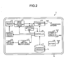
- FIG. 2 is a block diagram of a configuration of the capsule endoscope 2.
- the capsule endoscope 2 is covered with a casing.
- the casing has a shape like a capsule, which is formed in a size such that it can be easily introduced into the subject 1, and is formed of a casing main body 10a and an optical dome 10b (see FIG. 4 ).
- the casing main body 10a is a casing member having a cylindrical structure with one open end and the other closed end like a dome.
- the optical dome 10b is a transparent optical member formed into a shape like a dome.
- the optical dome 10b is attached to the casing main body 10a such that that the optical dome 10b seals the open end, which is one end of the casing main body 10a.
- the casing 10 formed of the casing main body 10a and the optical dome 10b houses each element of the capsule endoscope 2 in a watertight manner.
- the capsule endoscope 2 includes a light emitting device 29, which is realized using LEDs, and a light emitting device driver 11 that drives and controls the light emitting device 29.
- the light emitting device 29 and the light emitting device driver 11 serve as an illumination unit.
- the capsule endoscope 2 further includes an imaging device 20 that is a solid-state imaging device realized using a CCD or a CMOS; an imaging device driver 25 that drives and controls the imaging device 20; and an image signal processing circuit 21 that processes pixel signals, which are output from the imaging device 20, as an image signal.
- the imaging device 20, the imaging device driver 25, and the image signal processing circuit 21 serve as an imaging unit.
- a transmission unit 23 outputs the imaging information containing image information, which is output from the image signal processing circuit 21, as a radio signal from a transmission antenna 24.
- a distance detection unit 22 detects information on the distance between the object and the capsule endoscope 2 on the basis of the image information, which is output from the image signal processing circuit 21, or information from a controller 26.
- the controller 26 generally controls the capsule endoscope 2.
- the controller 26 determines the next image capturing mode by comparing the information on the distance, which is detected by the distance detection unit 22, with a threshold 12 about switching between image capturing modes stored in a storage unit 11, and the controller 26 controls the imaging device driver 25 and/or the light emitting device driver 10 such that an imaging process in the determined image capturing mode is performed.
- the image-capturing mode includes the normal light observation mode and the special light observation mode.
- the capsule endoscope 2 includes a battery 28, which is realized using a cell battery, and a power supply circuit 27 that supplies power to each element using the battery 28.
- FIG. 3 is a diagram of an arrangement of the light emitting device 29 in the capsule endoscope, viewed from the side of the optical dome.
- FIG. 4 is a vertical cross-sectional view (cross-sectional view taken along the line A-A) of a portion in which the illumination unit and the imaging unit are arranged and its neighboring portion.
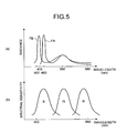
- FIG. 5 are graphs of wavelength dependence of radiance of the light emitting device and wavelength dependence of spectral sensitivity of the imaging device 20.
- the light emitting device 29 includes two types of light emitting devices that are alternately arranged annularly around the imaging device 20 and a lens 20a.
- the two types of light emitting devices are made up of four normal light emitting devices LA and four special light emitting devices LB and are arranged on a light source substrate 29a.
- the normal light emitting device LA is a white light source, in which a yellow phosphor is provided on a blue LED (in a range from about 450 nm to about 480 nm, preferably about 460 nm), represented by the curve FA in FIG. 5(a) .
- the special light emitting device LB is a white light source, in which a yellow phosphor is provided on a blue LED (in a range from about 415 nm to about 430 nm, preferably about 415 nm), represented by the curve FB in FIG. 5(a) .
- the yellow phosphor emits fluorescent light having a peak in a range from about 530 nm to about 560 nm according to the wavelength of light emitted by each blue LED.
- the normal light emitting device LA is realized as a normal white light source.
- the special light emitting device LB is also a white light source, but the peak wavelength of the radiance is around 415 nm. Blue light around 415 nm has features that blue light is easily absorbed by hemoglobin, thus is not reflected by a bleeding site and is reflected in a non-bleeding site, and that, in a shallow portion below the surface of the living body, blue light is absorbed in a blood vessel in the shallow portion.
- the special light emitting device LB has light distribution characteristics of an orientation angle equal to or more than 60 degrees, which is broader than that of the normal light emitting device LA. This is because, in the special light observation mode, an object close the capsule endoscope 2 is observed widely, and, in the normal light observation mode, an object separated from the capsule endoscope 2 is observed.
- the lens 20a that is positioned at the center of the longitudinal axis of the capsule endoscope 2 is arranged on the top part of the imaging device 20 in a lens barrel 20b. The lens 20a focuses the light, which is applied from the light emitting device 29 and reflected from the object, and forms an image on the imaging device 20.
- the lens barrel 20b and the imaging device 20 are arranged and fixed on an image-capturing substrate 20c.
- the imaging device 20 includes RGB color filters in a Bayer arrangement and has the spectral sensitivity wavelength dependence corresponding to the RGB as depicted in FIG. 5(b) .
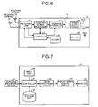
- the receiving device 3 decodes RF signals that are received by the receiving antennae 3a to 3h, and a reception signal processor 31 generates image information on the basis of the decoded signals and stores the image information in the portable recording medium 5 via a storage controller 32.
- a controller 33 generally controls the receiving device 3. The controller 33 selects a receiving antenna having the highest receiving electric field intensity from the receiving antennae 3a to 3h on the basis of the receiving electric field intensity of an RF signal, which is received by a receiving unit 30, and outputs an instruction for switching to the receiving unit 30.
- An I/O unit 34 inputs or outputs various types of instruction information.
- the I/O unit 34 is realized using, for example, a touch panel.
- the receiving device 3 includes a battery that is realized using a cell battery and includes a power supply circuit 36 that supplies power to each element using the battery 35.
- FIG. 7 is a block diagram of a configuration of the image display device 4.
- a controller 41 of the image display device 4 acquires imaging information that is input from the portable recording medium 5 and stores the imaging information in a storage unit 45 according to an instruction from an input unit 40. Thereafter, according to an instruction from the input unit 40, the controller 41 loads a desired image stored in the storage unit 45 and outputs and displays the image on a monitor 44 via a display device control circuit 43 after an image processing circuit 42 performs desired image processing on the image.
- the controller 26 controls the imaging device driver 25 and the light emitting device driver 10 to perform an imaging process at a predetermined timing, for example, at every 0.5 second (step S101).
- the distance detection unit 22 acquires information on the distance on the basis of the acquired imaging information or information from the controller 26 (step S102).
- the controller 26 determines whether the value of the information on the distance, such as the light emitting time, is larger the threshold 12 (step S103).
- step S104 When the value of the information on the distance is larger than the threshold 12 (YES at step S103), because the object and the capsule endoscope 2 are distant from each other, the controller 26 sets the image capturing mode to the normal light observation mode (step S104) and goes to step S106. In contrast, when the value of the information on the distance is not larger than the threshold 12 (NO at step S103), because the object and the capsule endoscope 2 are close to each other, the controller 26 sets the image capturing mode to the special light observation mode (step S105), and goes to step S106. At step S106, the controller 26 determines whether to end the imaging process.
- the controller 26 goes to step S101 and repeats the above-described imaging process in the imaging mode, which is set at step S104 or step S105.
- the controller 26 ends the process.
- the normal light observation mode both of the normal light emitting devices LA and the special light emitting devices LB are caused to emit light and an image is captured.
- the special light observation mode only the special light emitting devices LB are caused to emit light and an image is captured. At least information representing the imaging mode is added to the imaging information, which is captured as described above, and then the imagining information is transmitted to the receiving device 3.
- the controller 26 performs an automatic light adjustment control according to the acquired image information.
- the automatic light adjustment control adjusts the time during which the light emitting device 29 (LED) emits light.
- LED light emitting device
- the controller 26 determines whether the light emitting time exceeds a threshold tB. When the light emitting time exceeds the threshold tB, the controller 26 performs a process of changing the setting to the normal light observation mode M1. In contrast, when the image capturing mode is a normal light observation mode M1, the controller 26 determines whether the light emitting time is less than a threshold tAB. When the light emitting time is less than the threshold tAB, the controller 26 performs a process of changing the setting to the special light observation mode M2. In this example, in order to prevent contact bounce, the thresholds tAB and tB different from each other are used. Alternatively, the thresholds tAB and tB may be the same. In addition, in this example, the value of the drive current to each of the normal light emitting device LA and the special light emitting device LB is the same.
- the pixel average value of a high luminance portion in the acquired image is used as the brightness of the image.
- the controller 26 changes the setting to the normal light observation mode M1. In other words, in the special light observation mode M2, for an area EAB in which the brightness is less than the threshold Cth, the controller 26 changes the setting to the normal light observation mode M1.
- the threshold is Cth in both of the normal light observation mode M1 and the special light observation mode M2
- the normal light observation mode M1 when the normal light observation mode M1 is currently set, only the special light emitting devices LB are caused to emit light in advance and the brightness is detected.
- the normal light observation mode M1 When the brightness is less than the threshold Cth, the normal light observation mode M1 is maintained.
- the brightness is at the threshold Cth, it is preferable to change the setting to the special light observation mode M2 in view of power saving.
- a histogram of brightness of image may be obtained as depicted in FIG. 11 and, according to variations in the shape of a high luminance portion EC of the histogram, the distance between the capsule endoscope 2 and the object may be detected. For example, a curve Heb varies to a curve Heab with an increase in the distance. The distance may be detected from variations in the whole shape of the histogram.
- the distance detection unit 22 obtains the brightness of each of areas E0 to E4, including an area E0 at the center portion in a detection image 50 and four areas E1 to E4 in peripheral portions.
- Each of the areas E0 to E4 is an area of 10 ⁇ 10 pixels and the luminance is obtained as brightness.
- brightness Y 0.11 ⁇ B + 0.59 ⁇ G + 0.30 ⁇ R is obtained.
- the brightness may be obtained from, instead of the luminance, only red (R) components having the least absorbance characteristics in the body.
- the area E0 of the center portion and the areas E1 to E4 of the peripheral portions are detected, it can be detected whether an image is captured in the axial direction of the lumen.
- the brightness of the area E0 is less than a predetermined value A and the brightness of the areas E1 to E4 exceeds a predetermined value B, it can be determined that the image is captured in the axial direction of the lumen.
- setting be changed to the normal light observation mode M1.
- the acquired image has large irregularities if the distance to the object is large and has small irregularities if the distance to the object is small.
- the signal intensity of an image signal decreases as the space frequency increases, but the reduction represented by the curve Fb in the case of the large distance is larger and thus the difference between the signal intensity of the curve Fb and that of a curve Fa in the case of the small distance increases.
- the distance detection unit 22 can detect the distance by obtaining the space frequency distribution.
- the space frequency distribution is realized using FFT in which one-dimensional or two-dimensional processing is performed. When one-dimensional FFT processing is performed, multiple lines may be averaged. If the color filter has a Bayer arrangement, it is preferable that the space frequency of pixels of G components be obtained. This is because two of four pixels are of G components in the Bayer arrangement and thus the space frequency can be acquired accurately.
- the distance is detected according to whether the optical dome 10b makes a contact with the object.
- a pressure sensor 60 is provided and the distance detection unit 22 contacts with the object by receiving the result of measurement by the pressure sensor 60 from the controller 26.
- the pressure sensor 60 is provided to a connection portion between the optical dome 10b and the casing main body 10a.
- An elastic member 61 is provided between the optical dome 10b and the casing main body 10a and thus the optical dome 10b is movable toward the casing main body 10a in the longitudinal direction.
- the pressure sensor 60 is a pressing member having, for example, a shape like a spring.
- the pressure sensor 60 is realized using a MEMS device.
- the distance detection unit 22 determines that the optical dome 10b makes a contact with the object and detects that the distance between the object and the capsule endoscope 2 is small.
- the controller 26 sets the special light observation mode M2.
- the controller 26 sets the normal light observation mode M1.
- the controller 26 may further be provided with a contact image capturing mode M3 with much shorter exposure time, in which the luminance intensity by the light emitting device 29 is increased when the optical dome 10b makes a contact.
- a contact image capturing mode M3 with much shorter exposure time, in which the luminance intensity by the light emitting device 29 is increased when the optical dome 10b makes a contact.
- a small light absorption reaction of hemoglobin can be captured in an image without fail by increasing the luminance intensity, and the output of the imaging device 20 can be prevented from being saturated by shortening the exposure time in accordance with the increase in the luminance intensity.
- image processing for changing the level of highlighting the structure be performed on a portion 63 at which a contact has taken place.
- image processing for changing the level of highlighting the structure be performed on a portion 63 at which a contact has taken place.
- image processing By performing such image processing, blood capillaries on the surface of the digestive canal can be highlighted and displayed.
- Detection of the contact portion 63 can be realized by detecting a portion having brightness equal to or more than a certain value, having evenness, and having a space frequency component lower than that of peripheral areas, i.e., a portion with small irregularities.
- the image is yellow due to bilirubin.
- the optical dome 10b makes a contact with a living tissue, the bilirubin is pushed out from the imaging area and thus the yellow components are reduced.
- the information on the yellow components is contained in the information on the G pixels and R pixels.
- the ratio B/G of the signal intensity of the G with respect to the signal intensity of the B pixels is obtained and the ratio B/G exceeds a threshold, it can be determined that the optical dome 10b makes a contact with the living tissue. This is because, when a contact is made, B of the ratio does not change and G of the ratio becomes small, and accordingly the ratio B/G becomes large.
- the controller 26 When contacting, the controller 26 sets the special light observation mode M2. When the optical dome 10b does not make a contact with the living tissue, the controller 26 sets the normal light observation mode M1. When the optical dome 10b makes a contact with the living tissue, the contact image capturing mode M3 may be alternatively set furthermore as described above.
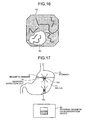
- a binocular capsule endoscope 102 replaces the capsule endoscope 2 and the capsule endoscope 102 includes a magnetic member 73 and a magnetic detection unit 74 that detects a magnetic field.
- An external magnetic field generation device 80 is provided outside the subject 1 and generates a magnetic field to the capsule endoscope 102 that floats in water 71 in a stomach 70. By varying the magnetic field, the capsule endoscope 102 is attracted vertically downward and thus it can be moved in the vertical direction.
- the distance detection unit 22 can detect the distance between the capsule endoscope 102 and a tissue surface 70a of the stomach 70, which is an object.
- the controller 26 can perform the above-described process for changing and setting the image capturing mode according to the result of the detection.
- the normal light emitting devices LA and the special light emitting devices LB are caused to emit light simultaneously.
- the normal light observation mode only the normal light emitting devices LA may emit light.
- only the normal light emitting devices LA may be caused to emit light in the normal light observation mode and only the special light emitting devices LB may be caused to emit light in the special light observation mode.
- each of the normal light emitting devices LA and the special light emitting devices LB is formed as an independent light emitting device.
- the normal light emitting device LA and the special light emitting device LB may be formed as an integrated LED.
- an integrated LED is realized in a way that an excitation LED 91 having a peak in a range from 415 nm to 430 nm and an excitation LED 92 having a peak in a range from 450 nm to 480 nm are formed in an LED main body 90 and a phosphor 93 having a fluorescent peak in a range from 530 nm to 560 nm is placed on and connected to the top portion of the LED main body 90.
- a light emitting device driver 11A is achieved by connecting the excitation LEDs 91 and 92 in parallel and providing a switch 91a connected in series with the excitation LED 91 and a switch 92a connected in series with the excitation LED 92.
- the controller 26 performs selective drive control to allow an arbitrary combination of light emission.
- Variable resistors may be respectively connected in series with the excitation LEDs 91 and 92 such that the current ratio in the excitation LEDs 91 and 92 can be changed.
- the luminance intensity may be changed not only by on/off of the switches 91a and 92a but also in an analog manner.
- an excitation LED having a peak of 400 nm may be further provided.
- three or more excitation LEDs may be used instead of two excitation LEDs 91 and 92.
- the ratio regarding the excitation light wavelength components of the normal light emitting devices LA and the emission wavelength components of the phosphor and the ratio regarding the excitation light wavelength components of the special light emitting devices LB and the emission wavelength components of the phosphor are set uniform such that the ratio of white balance correction value for image processing is uniform.
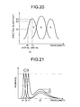
- the final received light intensity varies depending on the spectral sensitivity characteristics of the imaging device ( ⁇ 3 ⁇ ⁇ 2 ⁇ ⁇ 1).
- the spectral sensitivity-S3 of the imaging device with respect to the wavelength ⁇ 3 is smaller than the spectral sensitivity S1 of the imaging device with respect to the wavelength ⁇ 1
- the final received light intensity with respect to the wavelength ⁇ 3 is smaller than the received light intensity with respect to the wavelength ⁇ 1 (S3 ⁇ S2 ⁇ S1). Accordingly, the light receiving intensities results in different spectra.
- the peak radiances with respect to the wavelengths ⁇ 1 and ⁇ 3 are set equal such that the emission component ratio of the phosphor is reduced according to the spectral sensitivity characteristics of the B pixels of the imaging device.
- the material of the emission components of the phosphor is reduced such that the radiance of the emission components of the phosphor with respect to the peak wavelength ⁇ 0 (560 nm) in FIG. 21 decreases according to a decrease in the spectral sensitivity characteristics of the B pixels. Accordingly, even with the same peak value with respect to the wavelength ⁇ 1 and the wavelength ⁇ 2, the final received light intensity spectra from the light emitting devices is in the uniform shape.
- the material of the emission components of the phosphor may be set such that the values of radiance with respect to about the peak wavelength ⁇ 0 of the emission components of the phosphor is uniform, and the peak radiance with respect to the wavelength ⁇ 3 may be set larger than the peak radiance with respect to the wavelength ⁇ 1 such that a decrease in the spectral sensitivity characteristics of the B pixels is corrected.
- the shape of the final received light intensity spectrum from each light emitting device is uniform.
- an integral between the radiance characteristics of the normal light emitting device LA and the spectral sensitivity characteristics of the imaging device with respect to each of R, G, and B is obtained and specific values are set as ratios of the integrals (B/G, R/G). It is preferable that the ratio be about 1.
- an integral between the radiance characteristics of the normal light emitting device LB and the spectral sensitivity characteristics of the imaging device with respect to each of R, G, and B is obtained and ratio of the integrals are set as in the case of the normal light emitting device LA.
- the received light intensity spectrum is uniform and accordingly the white balance correction value in the image processing is uniform. Accordingly, the common white balance correction value is used in the image processing and thus the image processing can be performed easily. Particularly, even for images that are captured using different capsule endoscopes, this color component adjustment allows the image display device 4 to use a common white balance correction value, which reduces the load of image processing.
- the capsule endoscope 2 acquires the information on the distance in the above-described embodiment, but the present invention is not limited to this.
- the capsule endoscope 2 may receive information on the distance that is acquired by an external device. The received information on the distance is sent to the distance detection unit 22 via the controller 26.
- the capsule endoscope 2 needs to include a receiving mechanism and the receiving device 3 needs to include a transmission function.
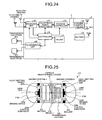
- the capsule endoscope 2 is provided with a pair of receiving electrodes 94a and 94b for in-vivo communications and a receiving unit 94 that receives a reception signal from the potential difference between the receiving electrodes 94a and 94b.
- the receiving device 3 is provided with a pair of transmission electrodes 96a and 96b and a transmission unit 95 that generates a potential difference between the transmission electrodes 96a and 96b and generates a transmission signal in the capsule endoscope 2 via the subject 1.
- the receiving device 3 can analyze an image and transmit information on the distance, such as the above-described brightness of the image and the space frequency, based on the result of the analysis to the capsule endoscope 2.
- the image capturing mode can be switched as described above by transmitting the magnetic field generation information on the external magnetic field generation device and by using the magnetic field information as the information on the distance.
- the information on the distance is output to the operation unit of the capsule endoscope 2 in the above-described embodiment, but the information on the distance may be output to the outside of the capsule endoscope 2.
- the information on the distance may be output to an operation unit of the receiving device 3 or an operation unit of the image processing device 4.
- a binocular capsule endoscope 202 is used that includes two imaging systems A and B respectively having different focal distances, includes a magnet 210, and that can be reversed using an external magnetic field.
- the capsule endoscope 202 includes optical domes 210a and 210b corresponding to the optical dome 10b on both ends in the longitudinal direction.
- the imaging system A having a long focal distance is provided on one end and the imaging system B having a short focal distance is provided on the other end.
- a battery 231, the magnet 210, and a transmission antenna 250 are mounted between the imaging systems A and B.
- light emitting devices 229a and 229b are arranged annularly around lenses 221a and 221b on control substrates 230a and 230b, respectively. Because the weight of the battery 231 is large, a ballast 240 serving as a weight member is provided on the opposite side with respect to the battery 231 such that the capsule gravitational center G of the capsule endoscope 202 is positioned at the center of the capsule endoscope 202.
- the capsule endoscope 202 can easily rotate in liquid.
- the external magnetic field generation device 80 controls the orientation of the magnetic field to be generated on the basis of the information on the distance, which is input.
- the external magnetic field generation device 80 orients the imaging system B having a short focal distance toward an in-vivo tissue T, which is an object.
- the external magnetic field generation device 80 orients the imaging system A having a long focal distance toward the in-vivo tissue T, which is an object (see FIG. 26 ).
- the image capturing condition is changed by changing the image capturing mode in the above-described embodiment, but the image capturing condition is changed here by selecting an imaging system having a focal distance corresponding to the distance.
- the operation unit serves as a magnetic field generation controller of the external magnetic field generation device 80.
- Image capturing condition Focal distance
- a capsule endoscope 302 includes a movable ballast 340 in place of the fixed ballast 240 of the capsule endoscope 202 and includes a ballast driver 310 that drives the ballast 340 to move.
- the configuration other than these aspects is the same as that of the capsule endoscope 202 in FIG. 25 .
- the ballast driver 310 is formed of SMA (shape memory alloy) that compresses and extends in the longitudinal direction. By applying a current to the SMA, the SMA compresses or extends and thus moves the ballast 340, thereby changing the position of the capsule gravity center G. By changing the position of the capsule gravity center G, the capsule endoscope 302 can be rotated and thus an imaging system can be selected according to the information on the distance.
- the operation unit serves as the ballast driver 310 of the capsule endoscope 302 and thus the image capturing condition is the above-described focal distance.
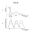
- the spectral sensitivity of the pixel B1 corresponds to the excitation light spectrum of the special light emitting device LB and the spectral sensitivity of the pixel B2 corresponds to the excitation light spectrum of the normal light emitting device LA.
- a normal light image is generated using R pixels, G pixels, and (B1+B2) pixels.
- a special light image blood absorbed light image
- B2 pixels and G pixels are separated.
- the G components are absorbed in a relatively thick blood vessel positioned in a portion deeper than that of a blood vessel in which B1 (blue) components are absorbed and accordingly the two blood vessels can be separated.
- one of two G pixels in a Bayer arrangement serves as a G1 pixel having a spectral sensitivity spectrum in a narrow band.
- B pixels and G1 pixels are used in the special light observation mode
- B pixels are used in the normal light observation mode.
- a clear special light image can be obtained.
- the normal light emitting devices LA and the special light emitting devices LB are used to obtain a normal light image and a special light image.
- three LEDs i.e., a white LED 401 that emits white light, a green LED 402 that emits green light, and a blue LED 403 that emits blue light are provided without a phosphor.
- the white LED 401 is caused to emit light.
- the green LED 402 and the blue LED 403 are caused to emit light.
- Mg (magenta) pixels are used instead of R pixels in a Bayer arrangement.
- the Mg pixel has the spectral sensitivity spectra covering those of the R pixel component and the B pixel component.
- the normal observation mode by outputting, as R pixel components, components obtained by subtracting the B pixel components from the Mg pixel components, an RGB normal light image can be obtained.
- the special light observation mode because only the green LED 402 and the blue LED 403 are cause to emit light, no light of R components is emitted.
- the B components can have doubled received light intensity of that of the B pixels because of a B pixel component area of the B pixel component and the Mg pixel component, and the G components can have doubled received light intensity because of two G pixels.
- doubled light receiving intensity of that with a Bayer arrangement can be obtained using one pixel array. Accordingly, a special light image with a high resolution can be obtained.
- a high-resolution special light image can be obtained using the light emitting device in FIG. 31 having the color filter arrangement in FIG. 33(a) .
- a W (white) pixel is provided instead of an R pixel in the Bayer arrangement.
- the W pixel has the spectral sensitivity spectrum covering the whole RGB area.
- Modification 2 different from Modification 1, in the normal light observation mode, all of the white LED 401, the green LED 402, and the blue LED 403 are caused to emit light, and R components are generated by subtracting a sum of B pixel components and G pixel components from the W pixel components.
- the green LED 402 and the blue LED 403 are cause to emit light.
- the B components can have doubled received light intensity of the B pixels because of the B pixel components and B components of the W pixel components, the G components can have doubled received light intensity because of two G pixels.
- doubled light receiving intensity can be obtained and accordingly a high-resolution special light image can be obtained.
- a normal light image can be obtained using RGB components and a special light image can be obtained using only GB components without R components.
- a normal light image and a special light image can be obtained when the special light emitting devices LB are used; therefore, it is preferable that, when the image display device 4 outputs and displays images, image processing for obtaining a normal light image and a special light image or display processing for displaying a normal light image and a special light image be performed.
- a normal light image can be obtained when only the normal light emitting devices LA are used or when the normal light emitting devices LA and the special light emitting devices LB are used.
- the capsule endoscope 2 transmits the image capturing mode information, which represents the image capturing condition, as additional information contained in the imaging information.
- the image display device 4 that receives the imaging information performs image processing on each image according to the process procedure in FIG. 35 . Specifically, first, it is determined whether the additional information corresponding to an image represents that the image is captured using only the special light emitting devices LB (step S201).
- step S202 a process for generating a normal light image, which is captured when the normal light emitting devices LA and the special light emitting devices LB, including a normal light image that is captured using only the normal light emitting devices LA, is performed (step S202) and the process ends.
- the normal light image generation process for an image that is captured using only the special light emitting devices LB is performed (step S203) in parallel with a special light image (blood absorption light image) generation process for an image that is captured in only the special light emitting device LB observation mode (step S204) and the process ends.
- the normal light image and the special light image can be displayed in. areas EP1 and EP2, respectively, on a display screen E of the monitor 44.
- an average color bar 500 is displayed in which a series of image groups are arranged according to the characteristic colors in the order the images are acquired.
- the average color bar 500 is a GUI. BY pointing a desired position on the average color bar 500, an image corresponding to the desired position is output and displayed or images are sequentially output and displayed and from the image corresponding to the desired position.
- an image capturing mode display bar 501 connected to the top part of the average color bar 500, for outputting and displaying an area 501a of images is provided in the same order the images are acquired.
- the area 501a on the image capturing mode display bar 501 represents that special light image can be displayed in addition to the display of normal light images. If all the images are captured using only the special light emitting devices LB, the area 501a on the image capturing mode display bar 501 can be output and displayed as an area for which it is preferable that special light images be displayed. Determination on the preferability of the area is made according to the information on the distance added to the imaging information or the determination result based on the information on the distance. When the distance is shorter than a threshold, the area is displayed as an area with the preferability.
- any one of the normal light observation mode or the special light observation mode is selected and set.
- the selected and set image capturing mode serves as the image capturing mode for the next image capturing.
- Setting and changing of the image capturing mode may be performed from the chronological point of view. For example, an alternate image capturing mode, in which the normal light observation mode and the special light observation mode are used alternately according to the image capturing condition, and a temporary image capturing mode, in which an image capturing mode that is selected and set temporarily as an interrupt is performed only once, may be provided.
Landscapes
- Health & Medical Sciences (AREA)
- Life Sciences & Earth Sciences (AREA)
- Surgery (AREA)
- Engineering & Computer Science (AREA)
- Physics & Mathematics (AREA)
- Optics & Photonics (AREA)
- Medical Informatics (AREA)
- General Health & Medical Sciences (AREA)
- Pathology (AREA)
- Nuclear Medicine, Radiotherapy & Molecular Imaging (AREA)
- Biomedical Technology (AREA)
- Heart & Thoracic Surgery (AREA)
- Biophysics (AREA)
- Molecular Biology (AREA)
- Animal Behavior & Ethology (AREA)
- Radiology & Medical Imaging (AREA)
- Public Health (AREA)
- Veterinary Medicine (AREA)
- Signal Processing (AREA)
- Microelectronics & Electronic Packaging (AREA)
- Spectroscopy & Molecular Physics (AREA)
- Multimedia (AREA)
- Endoscopes (AREA)
- Measurement Of The Respiration, Hearing Ability, Form, And Blood Characteristics Of Living Organisms (AREA)
Abstract
Description
- The present invention relates to a capsule endoscope device that is put into a living body and acquires in-vivo images of a living tissue.
- In recent years, in the field of endoscopy, swallowable capsule endoscopes have been developed. Such a capsule endoscope has an image capturing function and a radio function, and has a function in which, after being swallowed by a patient for observing the body cavity, the capsule endoscope moves through the internal organs, such as the esophagus, stomach, and small intestine, by peristalsis of the internal organs and sequentially captures images until it is naturally excreted from the human body.
- Patent Document 1 describes an in-vivo imaging device that, during an image capturing period, turns on a light source, records the amount of light reflected to the imaging device, and controls the gain level of an image of an imaging unit.
-
Patent Document 2 describes a technology in which a distance sensor detects the distance from the object and determines that the capsule endoscope has been swallowed into a subject when the distance is equal to or smaller than a predetermined value and then switches on a subswitch, thereby collecting images while reducing waste power consumption. - Patent Document 3 describes a system that includes an in-vivo state tester, such as an in-vivo pH tester, and that changes the operation mode according to the in-vivo state that is acquired by the in-vivo state tester.
-
- Patent Document 1: Japanese Laid-open Patent publication No.
2006-524097 - Patent Document 2: Japanese Laid-open Patent publication No.
2005-73887 - Patent Document 3: Japanese Laid-open Patent publication No.
2006-509574 - There are cases where living tissues take different object shapes or states depending on parts inside body cavity. In obtaining images of objects, without preparing various image capturing conditions corresponding to the different object shapes or states, desired images cannot be obtained and furthermore wasted images may sometimes be obtained.
- The present invention has been achieved in view of the foregoing, and an object of the present invention is to provide a capsule endoscope device capable of obtaining a desired image corresponding to different object shapes or states.
- To solve the problem described above and achieve the object, a capsule endoscope device according to the present invention includes: an illumination unit that illuminates a living tissue; an imaging unit that captures an image of the living tissue; a transmission unit that transmits imaging information containing the image captured by the imaging unit; a storage unit that stores a threshold with respect to information on a distance between the capsule endoscope device and the living tissue; a detection unit that detects the information on the distance between the capsule endoscope device and the living tissue; and an output unit that compares the information on the distance detected by the detection unit with the threshold, selects an image capturing condition based on a result of the comparing, and outputs the selected image capturing condition to an operation unit that relates to image capturing.
- In the capsule endoscope device according to the present invention as set forth in the invention described above, the detection unit detects, as the information on the distance, at least one of an amount of variation in brightness of the image, an amount of variation in space frequency of the image, and an amount of variation in exposure time.
- In the capsule endoscope device according to the present invention as set forth in the invention described above, a plurality of imaging units that have image capturing functions for the respective image capturing conditions are further included, wherein the output unit compares the information on the distance detected by the detection unit with the threshold, selects an image capturing condition based on the result of the comparing, and outputs the selected image capturing condition to an image capturing unit corresponding to the selected image capturing condition to operate.
- In the capsule endoscope device according to the present invention as set forth in the invention described above, a plurality of the illumination units having illuminating functions for the respective image capturing conditions are included, wherein the output unit compares the information on the distance detected by the detection unit with the threshold, selects an image capturing condition on the basis of the comparison result, and outputs the selected image capturing condition to the illumination unit corresponding to the selected image capturing condition to operate.
- In the capsule endoscope device according to the present invention as set forth in the invention described above, each of the illumination units includes at least a white light illumination unit that emits white light and a special light illumination unit that emits specific visible light components, and the output unit compares the information on the distance detected by the detection unit with the threshold, selects an image capturing condition on the basis of the comparison result, and outputs the selected image capturing condition to the white light illumination unit and/or the special light illumination unit corresponding to the selected image capturing condition to operate.
- In the capsule endoscope device according to the present invention as set forth in the invention described above, an adjustment unit that adjusts a position of the center of gravity of the capsule endoscope device is further included, wherein the output unit compares the information on the distance detected by the detection unit with the threshold, selects an image capturing condition based on the result of the comparing, and outputs the selected image capturing condition to the adjustment unit to perform an adjustment operation.
- In the capsule endoscope device according to the present invention as set forth in the invention described above, a magnetic member that is guided by a magnetic guidance device that is provided outside is further included, wherein the detection unit detects, as the information on the distance, a magnetic field that is applied to the magnetic member, and the output unit compares the information on the distance detected by the detection unit with the threshold, selects an image capturing condition based on the result of the comparing, and outputs the selected image capturing condition to the operation unit that relates to image capturing.
- According to the present invention, the output unit compares the information on the distance detected by the detection unit with the threshold, selects an image capturing condition on the basis of the comparison result, and outputs the selected image capturing condition to the operation unit that relates to image capturing in order to optimize the image capturing condition, and thus a desired image corresponding to different object shapes or states can be obtained.
-
-
FIG. 1 is a schematic diagram of a schematic configuration of a capsule endoscope system that employs a capsule endoscope that is an embodiment of the present invention. -
FIG. 2 is a block diagram of a configuration of the capsule endoscope inFIG. 1 . -
FIG. 3 is a diagram of an arrangement of light emitting devices. -
FIG. 4 is a cross-sectional view taken along the line A-A inFIG. 3 , illustrating a configuration in the vicinity of an optical dome inFIG. 3 . -
FIG. 5 is a diagram illustrating examples of the radiance spectrum of a light emitting device and a spectral sensitivity spectrum of the imaging device. -
FIG. 6 is a block diagram of a configuration of a receiving device. -
FIG. 7 is a block diagram of a configuration of an image display device. -
FIG. 8 is a flowchart of a procedure of a process for switching between image capturing modes, which is performed by a controller. -
FIG. 9 is a diagram illustrating an example in which switching is performed between the image capturing modes according to the light emitting time. -
FIG. 10 is a diagram illustrating distance dependence of brightness of an image. -
FIG. 11 is a histogram of the brightness, which is captured in the special light observation mode, corresponding to the imaging distance variation. -
FIG. 12 is a diagram of an example of detecting the brightness of an image. -
FIG. 13 is a a diagram illustrating the space frequency dependence of the signal intensity, taking the distance as a parameter. -
FIG. 14 is a diagram of a configuration of the capsule endoscope inFIG. 2 to which a pressure sensor is added. -
FIG. 15 is a diagram of a configuration of the capsule endoscope added with the pressure sensor. -
FIG. 16 is a diagram illustrating an example of an image with its optical dome making a contact with an in-vivo tissue. -
FIG. 17 is a schematic diagram of an example in which a magnetic field from an external magnetic field generation device is applied to move the capsule endoscope device. -
FIG. 18 is an exploded perspective view of a light emitting device formed with a pair of a normal light emitting device and a special light emitting device. -
FIG. 19 is a circuit diagram of an example of a light emitting device drive circuit for the light emitting device inFIG. 18 . -
FIG. 20 is a diagram illustrating the variation in light receiving intensity by spectral sensitivity spectrum of the imaging device. -
FIG. 21 is a diagram illustrating an example of luminescence spectrum in a case in which the excitation light wavelength of each light emitting device is set uniform and the wavelength of light emitted from a phosphor is varied so that the received light intensity is set uniform. -
FIG. 22 is a diagram illustrating another example of luminescence spectrum in a case in which the wavelength of light emitted from the phosphor is set almost the same and, the shorter the excitation light wavelength of the light emitting device is, the higher the peak is set, so that the received light intensity is set uniform. -
FIG. 23 is a diagram of a configuration of a capsule endoscope device that can receive a signal from outside by in-vivo communications. -
FIG. 24 is a diagram of a configuration of a receiving device capable of transmission to the capsule endoscope device by in-vivo communications. -
FIG. 25 is a diagram of a configuration example of a capsule endoscope device including two image capturing systems. -
FIG. 26 is a diagram of a state in which magnetic guidance and reverse processing are performed on the capsule endoscope device inFIG. 25 . -
FIG. 27 is a diagram of a configuration of a capsule endoscope device including two image capturing systems and having a function for shifting the center of gravity. -
FIG. 28 is a diagram of a modification of an arrangement of color filters and the spectral sensitivity spectrum. -
FIG. 29 is a diagram of a modification of an arrangement of color filters and the spectral sensitivity spectrum. -
FIG. 30 is a diagram of a modification of an arrangement of color filters and the spectral sensitivity spectrum. -
FIG. 31 is a diagram of a configuration of a modification of the light emitting device. -
FIG. 32 is a diagram of a configuration of an example of a color filter corresponding to the light emitting device inFIG. 31 . -
FIG. 33 is a diagram of a configuration of another example of a color filter corresponding to the light emitting device inFIG. 31 . -
FIG. 34 is a diagram illustrating an example of the spectral sensitivity spectrum corresponding to the special light emitting device. -
FIG. 35 is a flowchart of a procedure of image processing performed by the image display device. -
FIG. 36 is a diagram of an example of a display screen of the image display device. - Exemplary embodiments of a capsule endoscope device according to the present invention will be described below with reference to the drawings.
- First,
FIG. 1 is a schematic diagram of a schematic configuration of a capsule endoscope system according to an embodiment. As depicted inFIG. 1 , the capsule endoscope system includes acapsule endoscope 2 that captures in-vivo images of a subject 1 and serves as a capsule endoscope device; a receiving device 3 that receives in-vivo images of the subject 1 from thecapsule endoscope 2 that is introduced into the subject; an image display device 4 that displays the in-vivo images of the subject 1, which are received by the receiving device 3; and aportable recording medium 5 for receiving and transferring data between the receiving device 3 and the image display device 4. - After being swallowed by the subject 1, the
capsule endoscope 2 sequentially captures in-vivo images of the subject 1 while moving through the internal organs of the subject 1 by, for example, peristalsis. Each time thecapsule endoscope 2 captures in-vivo images of the subject 1, thecapsule endoscope 2 sequentially transmits by radio imaging information containing the captured images to the receiving device 3 outside. In this case, thecapsule endoscope 2 sequentially transmits each in-vivo image of the subject 1 at time intervals corresponding to unique functions of thecapsule endoscope 2. - The receiving device 3 receives the group of in-vivo images of the subject, which are captured by the
capsule endoscope 2, and stores the received in-vivo image group. Specifically, the receiving device 3 includes a plurality of receivingantennae 3a to 3h. The receivingantennae 3a to 3h are attached to (carried by) the subject 1 having internal organs to which thecapsule endoscope 2 is introduced. The receiving device 3 sequentially receives the imaging information, which is transmitted by thecapsule endoscope 2 in the subject 1, via the receivingantennae 3a to 3h and thus acquires the group of in-vivo images of the subject 1. The receiving device 3 includes theportable recording medium 5, which is detachably attached, and records the group of in-vivo images of the subject 1, which is acquired from thecapsule endoscope 2, in theportable recording medium 5. - The receiving
antennae 3a to 3h are separately arranged, for example, along the path in which thecapsule endoscope 2, which is introduced into the internal organs of the subject 1, moves (the digestive canal of the subject 1) on the body surface of the subject 1 and are connected to the above-described receiving device 3. The receivingantennae 3a to 3h capture the imaging information, which is transmitted by thecapsule endoscope 2 in the subject 1, and sequentially transmits the captured imaging information to the receiving device 3. The receivingantennae 3a to 3h may be separately arranged on a jacket that the subject 1 wears. It is sufficient if one or more receiving antennae that capture the imaging information be arranged on the subject 1. The number of receiving antenna is not limited to eight. - The image display device 4 has a configuration like that of a work station that acquires various types of data, such as a group of in-vivo images of the subject 1, via the
portable recording medium 5 and displays the acquired various types of data on the display. Specifically, theportable recording medium 5, which records the group of in-vivo images of the subject 1, is detachably attached to the image display device 4, and the image display device 4 loads the group of in-vivo images of the subject 1 from the attachedportable recording medium 5. In this case, the image display device 4 acquires the group of in-vivo images that are identified by the receiving device 3 according to each function unique to thecapsule endoscope 2. The image display device 4 sores and manages the group of in-vivo images, which is acquired as described above, according to each function unique to thecapsule endoscope 2 and displays each in-vivo image being distinguished according to each function unique to thecapsule endoscope 2. Because the image display device 4 distinguishes and displays each in-vivo image of the subject 1, a user, such as a doctor or a nurse, can observe (examine) each in-vivo image of the subject 1 easily and efficiently. The user diagnoses the subject 1 by observing each in-vivo image of the subject 1 that is displayed by the image display device 4. - The
portable recording medium 5 is a recording medium that can be carried and is used for receiving and transferring data between the receiving device 3 and the image display device 4. Specifically, theportable recording medium 5 is configured to be attachable to and detachable from the receiving device 3 and the image display device 4 and to output and record data when it is attached to the receiving device 3 and the image display device 4. When being attached to the receiving device 3, theportable recording medium 5 records the group of in-vivo images of the subject 1, which are received by the receiving device 3 from thecapsule endoscope 2. When being attached to the image display device 4, theportable recording medium 5 sends the recorded data, such as the group of in-vivo images of the subject 1, to the image display device 4. - The various types of data that the
portable recording medium 5 records are, for example, the group of in-vivo images of the subject 1, time information (image-capturing time, receiving time) regarding each in-vivo image of the in-vivo image group, patient information on the subject 1, examination information on the subject 1, and image capturing mode information. The patient information on the subject 1 is specific information that specifies the subject 1, such as the patient name, date of birth, sex, age. The examination information on the subject 1 is specific information that specifies the examination for observing the internal organs by introducing thecapsule endoscope 2 into the internal organs, such as the examination ID and examination date. The image capturing mode information is information representing an image capturing mode during image capturing that is a normal light observation mode or a special light observation mode, which will be described below. -
FIG. 2 is a block diagram of a configuration of thecapsule endoscope 2. Thecapsule endoscope 2 is covered with a casing. The casing has a shape like a capsule, which is formed in a size such that it can be easily introduced into the subject 1, and is formed of a casingmain body 10a and anoptical dome 10b (seeFIG. 4 ). The casingmain body 10a is a casing member having a cylindrical structure with one open end and the other closed end like a dome. Theoptical dome 10b is a transparent optical member formed into a shape like a dome. Theoptical dome 10b is attached to the casingmain body 10a such that that theoptical dome 10b seals the open end, which is one end of the casingmain body 10a. Thecasing 10 formed of the casingmain body 10a and theoptical dome 10b houses each element of thecapsule endoscope 2 in a watertight manner. - The
capsule endoscope 2 includes alight emitting device 29, which is realized using LEDs, and a light emittingdevice driver 11 that drives and controls thelight emitting device 29. Thelight emitting device 29 and the light emittingdevice driver 11 serve as an illumination unit. Thecapsule endoscope 2 further includes animaging device 20 that is a solid-state imaging device realized using a CCD or a CMOS; animaging device driver 25 that drives and controls theimaging device 20; and an imagesignal processing circuit 21 that processes pixel signals, which are output from theimaging device 20, as an image signal. Theimaging device 20, theimaging device driver 25, and the imagesignal processing circuit 21 serve as an imaging unit. Atransmission unit 23 outputs the imaging information containing image information, which is output from the imagesignal processing circuit 21, as a radio signal from atransmission antenna 24. - A distance detection unit 22 detects information on the distance between the object and the
capsule endoscope 2 on the basis of the image information, which is output from the imagesignal processing circuit 21, or information from acontroller 26. Thecontroller 26 generally controls thecapsule endoscope 2. Thecontroller 26 determines the next image capturing mode by comparing the information on the distance, which is detected by the distance detection unit 22, with athreshold 12 about switching between image capturing modes stored in astorage unit 11, and thecontroller 26 controls theimaging device driver 25 and/or the light emittingdevice driver 10 such that an imaging process in the determined image capturing mode is performed. The image-capturing mode includes the normal light observation mode and the special light observation mode. Thecapsule endoscope 2 includes abattery 28, which is realized using a cell battery, and a power supply circuit 27 that supplies power to each element using thebattery 28. - A detailed configuration of the illumination unit and the imaging unit will be described.
FIG. 3 is a diagram of an arrangement of thelight emitting device 29 in the capsule endoscope, viewed from the side of the optical dome.FIG. 4 is a vertical cross-sectional view (cross-sectional view taken along the line A-A) of a portion in which the illumination unit and the imaging unit are arranged and its neighboring portion.FIG. 5 are graphs of wavelength dependence of radiance of the light emitting device and wavelength dependence of spectral sensitivity of theimaging device 20. As depicted inFIGS. 3 and5(a) , thelight emitting device 29 includes two types of light emitting devices that are alternately arranged annularly around theimaging device 20 and alens 20a. The two types of light emitting devices are made up of four normal light emitting devices LA and four special light emitting devices LB and are arranged on alight source substrate 29a. - The normal light emitting device LA is a white light source, in which a yellow phosphor is provided on a blue LED (in a range from about 450 nm to about 480 nm, preferably about 460 nm), represented by the curve FA in
FIG. 5(a) . In contrast, the special light emitting device LB is a white light source, in which a yellow phosphor is provided on a blue LED (in a range from about 415 nm to about 430 nm, preferably about 415 nm), represented by the curve FB inFIG. 5(a) . The yellow phosphor emits fluorescent light having a peak in a range from about 530 nm to about 560 nm according to the wavelength of light emitted by each blue LED. The normal light emitting device LA is realized as a normal white light source. The special light emitting device LB is also a white light source, but the peak wavelength of the radiance is around 415 nm. Blue light around 415 nm has features that blue light is easily absorbed by hemoglobin, thus is not reflected by a bleeding site and is reflected in a non-bleeding site, and that, in a shallow portion below the surface of the living body, blue light is absorbed in a blood vessel in the shallow portion. Thus, by processing an image, which is obtained using irradiation by the special light emitting device LBs, special observation can be performed in which blood-absorbed light image clearly representing a bleeding site is obtained. In this embodiment, in the normal light observation mode, both of the normal light emitting devices LA and the special light emitting devices LB are caused to emit light. In the special light observation mode, only the special light emitting devices LB are caused to emit light. - As depicted in
FIG. 4 , the special light emitting device LB has light distribution characteristics of an orientation angle equal to or more than 60 degrees, which is broader than that of the normal light emitting device LA. This is because, in the special light observation mode, an object close thecapsule endoscope 2 is observed widely, and, in the normal light observation mode, an object separated from thecapsule endoscope 2 is observed. Thelens 20a that is positioned at the center of the longitudinal axis of thecapsule endoscope 2 is arranged on the top part of theimaging device 20 in alens barrel 20b. Thelens 20a focuses the light, which is applied from thelight emitting device 29 and reflected from the object, and forms an image on theimaging device 20. Thelens barrel 20b and theimaging device 20 are arranged and fixed on an image-capturingsubstrate 20c. Theimaging device 20 includes RGB color filters in a Bayer arrangement and has the spectral sensitivity wavelength dependence corresponding to the RGB as depicted inFIG. 5(b) . - As illustrated in
FIG. 6 , the receiving device 3 decodes RF signals that are received by the receivingantennae 3a to 3h, and a reception signal processor 31 generates image information on the basis of the decoded signals and stores the image information in theportable recording medium 5 via a storage controller 32. Acontroller 33 generally controls the receiving device 3. Thecontroller 33 selects a receiving antenna having the highest receiving electric field intensity from the receivingantennae 3a to 3h on the basis of the receiving electric field intensity of an RF signal, which is received by a receiving unit 30, and outputs an instruction for switching to the receiving unit 30. An I/O unit 34 inputs or outputs various types of instruction information. The I/O unit 34 is realized using, for example, a touch panel. The receiving device 3 includes a battery that is realized using a cell battery and includes apower supply circuit 36 that supplies power to each element using the battery 35. -
FIG. 7 is a block diagram of a configuration of the image display device 4. As depicted inFIG. 7 , a controller 41 of the image display device 4 acquires imaging information that is input from theportable recording medium 5 and stores the imaging information in a storage unit 45 according to an instruction from an input unit 40. Thereafter, according to an instruction from the input unit 40, the controller 41 loads a desired image stored in the storage unit 45 and outputs and displays the image on a monitor 44 via a display device control circuit 43 after an image processing circuit 42 performs desired image processing on the image. - A procedure of an image capturing mode switching setting process performed by the
capsule endoscope 2 will be described here with reference to the flowchart inFIG. 8 . InFIG. 8 , first, thecontroller 26 controls theimaging device driver 25 and the light emittingdevice driver 10 to perform an imaging process at a predetermined timing, for example, at every 0.5 second (step S101). The distance detection unit 22 then acquires information on the distance on the basis of the acquired imaging information or information from the controller 26 (step S102). Thereafter, thecontroller 26 determines whether the value of the information on the distance, such as the light emitting time, is larger the threshold 12 (step S103). When the value of the information on the distance is larger than the threshold 12 (YES at step S103), because the object and thecapsule endoscope 2 are distant from each other, thecontroller 26 sets the image capturing mode to the normal light observation mode (step S104) and goes to step S106. In contrast, when the value of the information on the distance is not larger than the threshold 12 (NO at step S103), because the object and thecapsule endoscope 2 are close to each other, thecontroller 26 sets the image capturing mode to the special light observation mode (step S105), and goes to step S106. At step S106, thecontroller 26 determines whether to end the imaging process. When the imaging process is not to be ended (NO at step S106), thecontroller 26 goes to step S101 and repeats the above-described imaging process in the imaging mode, which is set at step S104 or step S105. When the imaging process is to be ended (YES at step S106), thecontroller 26 ends the process. As described above, in the normal light observation mode, both of the normal light emitting devices LA and the special light emitting devices LB are caused to emit light and an image is captured. In the special light observation mode, only the special light emitting devices LB are caused to emit light and an image is captured. At least information representing the imaging mode is added to the imaging information, which is captured as described above, and then the imagining information is transmitted to the receiving device 3. - A specific example of the information on the distance will be described here. The
controller 26 performs an automatic light adjustment control according to the acquired image information. The automatic light adjustment control adjusts the time during which the light emitting device 29 (LED) emits light. When thecapsule endoscope 2 and the object are distant from each other, because the amount of light reflected from the object is small and thus it is dark, the time during which thelight emitting device 29 emits light is adjusted to be longer. When thecapsule endoscope 2 and the object are close to each other, because the amount of light reflected from the object is large, the time during which thelight emitting device 29 emits light is adjusted to be shorter. In other words, by detecting the time during which thelight emitting device 29 emits light, the distance between thecapsule endoscope 2 and the object can be detected. - As depicted in
FIG. 9 , when the currently-set image capturing mode is a special light observation mode M2, thecontroller 26 determines whether the light emitting time exceeds a threshold tB. When the light emitting time exceeds the threshold tB, thecontroller 26 performs a process of changing the setting to the normal light observation mode M1. In contrast, when the image capturing mode is a normal light observation mode M1, thecontroller 26 determines whether the light emitting time is less than a threshold tAB. When the light emitting time is less than the threshold tAB, thecontroller 26 performs a process of changing the setting to the special light observation mode M2. In this example, in order to prevent contact bounce, the thresholds tAB and tB different from each other are used. Alternatively, the thresholds tAB and tB may be the same. In addition, in this example, the value of the drive current to each of the normal light emitting device LA and the special light emitting device LB is the same. - A case in which the brightness of an image is detected as the information on the distance will be described below. The pixel average value of a high luminance portion in the acquired image is used as the brightness of the image. As represented in
FIG. 10 , with an increase in the distance between thecapsule endoscope 2 and the object, the pixel average value of the high luminance portion is out of the saturated state at a certain distance and then decreases. Thus, when the currently-set image capturing mode is the special light observation mode M2 and the brightness of the image decreases to be less than a threshold Cth, thecontroller 26 changes the setting to the normal light observation mode M1. In other words, in the special light observation mode M2, for an area EAB in which the brightness is less than the threshold Cth, thecontroller 26 changes the setting to the normal light observation mode M1. - Here, for an area EB in which the threshold is Cth in both of the normal light observation mode M1 and the special light observation mode M2, when the normal light observation mode M1 is currently set, only the special light emitting devices LB are caused to emit light in advance and the brightness is detected. When the brightness is less than the threshold Cth, the normal light observation mode M1 is maintained. When the brightness is at the threshold Cth, it is preferable to change the setting to the special light observation mode M2 in view of power saving.
- Instead of the pixel average value of the high luminance portion, a histogram of brightness of image may be obtained as depicted in
FIG. 11 and, according to variations in the shape of a high luminance portion EC of the histogram, the distance between thecapsule endoscope 2 and the object may be detected. For example, a curve Heb varies to a curve Heab with an increase in the distance. The distance may be detected from variations in the whole shape of the histogram. - As depicted in
FIG. 12 , the brightness not of the whole pixels of a detection image but of a part of the pixels may be detected. InFIG. 12 , the distance detection unit 22 obtains the brightness of each of areas E0 to E4, including an area E0 at the center portion in adetection image 50 and four areas E1 to E4 in peripheral portions. Each of the areas E0 to E4 is an area of 10×10 pixels and the luminance is obtained as brightness. In other words, brightness Y = 0.11·B + 0.59·G + 0.30·R is obtained. The brightness may be obtained from, instead of the luminance, only red (R) components having the least absorbance characteristics in the body. - In this case, because the area E0 of the center portion and the areas E1 to E4 of the peripheral portions are detected, it can be detected whether an image is captured in the axial direction of the lumen. In other words, when the brightness of the area E0 is less than a predetermined value A and the brightness of the areas E1 to E4 exceeds a predetermined value B, it can be determined that the image is captured in the axial direction of the lumen. When the image is captured in the axial direction of the lumen, it is preferable that setting be changed to the normal light observation mode M1. By adding this image capturing condition for the process of switching the image capturing mode, the fine witching process can be performed.
- A case in which the space frequency of an image is detected as the information on the distance will be described. The acquired image has large irregularities if the distance to the object is large and has small irregularities if the distance to the object is small. In other words, as represented in
FIG. 13 , in both of the case in which the distance to the object is small and the case in which the distance is large, the signal intensity of an image signal decreases as the space frequency increases, but the reduction represented by the curve Fb in the case of the large distance is larger and thus the difference between the signal intensity of the curve Fb and that of a curve Fa in the case of the small distance increases. - In other words, the distance detection unit 22 can detect the distance by obtaining the space frequency distribution. The space frequency distribution is realized using FFT in which one-dimensional or two-dimensional processing is performed. When one-dimensional FFT processing is performed, multiple lines may be averaged. If the color filter has a Bayer arrangement, it is preferable that the space frequency of pixels of G components be obtained. This is because two of four pixels are of G components in the Bayer arrangement and thus the space frequency can be acquired accurately.
- Here, the distance is detected according to whether the
optical dome 10b makes a contact with the object. As depicted inFIG. 14 , apressure sensor 60 is provided and the distance detection unit 22 contacts with the object by receiving the result of measurement by thepressure sensor 60 from thecontroller 26. As depicted inFIG. 15 , thepressure sensor 60 is provided to a connection portion between theoptical dome 10b and the casingmain body 10a. Anelastic member 61 is provided between theoptical dome 10b and the casingmain body 10a and thus theoptical dome 10b is movable toward the casingmain body 10a in the longitudinal direction. Thepressure sensor 60 is a pressing member having, for example, a shape like a spring. Thepressure sensor 60 is realized using a MEMS device. When theoptical dome 10b makes a contact with, for example, the wall of the digestive canal, thepressure sensor 60 compresses due to the pressing and the pressure is detected by detecting the deformation electrically or mechanically. - When the pressure measured by the
pressure sensor 60 exceeds thethreshold 13, the distance detection unit 22 determines that theoptical dome 10b makes a contact with the object and detects that the distance between the object and thecapsule endoscope 2 is small. When the distance is small, thecontroller 26 sets the special light observation mode M2. When the distance is large, thecontroller 26 sets the normal light observation mode M1. - The
controller 26 may further be provided with a contact image capturing mode M3 with much shorter exposure time, in which the luminance intensity by thelight emitting device 29 is increased when theoptical dome 10b makes a contact. In the contact image capturing mode M3, a small light absorption reaction of hemoglobin can be captured in an image without fail by increasing the luminance intensity, and the output of theimaging device 20 can be prevented from being saturated by shortening the exposure time in accordance with the increase in the luminance intensity. - As depicted in
FIG. 16 , it is preferable that image processing for changing the level of highlighting the structure be performed on aportion 63 at which a contact has taken place. By performing such image processing, blood capillaries on the surface of the digestive canal can be highlighted and displayed. Detection of thecontact portion 63 can be realized by detecting a portion having brightness equal to or more than a certain value, having evenness, and having a space frequency component lower than that of peripheral areas, i.e., a portion with small irregularities. - When the small intestine is observed, the image is yellow due to bilirubin. On the other hand, when the
optical dome 10b makes a contact with a living tissue, the bilirubin is pushed out from the imaging area and thus the yellow components are reduced. The information on the yellow components is contained in the information on the G pixels and R pixels. Thus, for example, when the ratio B/G of the signal intensity of the G with respect to the signal intensity of the B pixels is obtained and the ratio B/G exceeds a threshold, it can be determined that theoptical dome 10b makes a contact with the living tissue. This is because, when a contact is made, B of the ratio does not change and G of the ratio becomes small, and accordingly the ratio B/G becomes large. - When contacting, the
controller 26 sets the special light observation mode M2. When theoptical dome 10b does not make a contact with the living tissue, thecontroller 26 sets the normal light observation mode M1. When theoptical dome 10b makes a contact with the living tissue, the contact image capturing mode M3 may be alternatively set furthermore as described above. - Here, magnetic information is used as the information on the distance. As depicted in
FIG. 17 , abinocular capsule endoscope 102 replaces thecapsule endoscope 2 and thecapsule endoscope 102 includes amagnetic member 73 and amagnetic detection unit 74 that detects a magnetic field. An external magneticfield generation device 80 is provided outside the subject 1 and generates a magnetic field to thecapsule endoscope 102 that floats inwater 71 in astomach 70. By varying the magnetic field, thecapsule endoscope 102 is attracted vertically downward and thus it can be moved in the vertical direction. - By detecting the size of the magnetic field from the
magnetic detection unit 74 via thecontroller 26, the distance detection unit 22 can detect the distance between thecapsule endoscope 102 and atissue surface 70a of thestomach 70, which is an object. Thecontroller 26 can perform the above-described process for changing and setting the image capturing mode according to the result of the detection. - In the above-described normal light observation mode, the normal light emitting devices LA and the special light emitting devices LB are caused to emit light simultaneously. Alternatively, in the normal light observation mode, only the normal light emitting devices LA may emit light. In other words, only the normal light emitting devices LA may be caused to emit light in the normal light observation mode and only the special light emitting devices LB may be caused to emit light in the special light observation mode.
- In the
light emitting device 29, each of the normal light emitting devices LA and the special light emitting devices LB is formed as an independent light emitting device. Alternatively, the normal light emitting device LA and the special light emitting device LB may be formed as an integrated LED. - For example, as depicted in
FIG. 18 , an integrated LED is realized in a way that anexcitation LED 91 having a peak in a range from 415 nm to 430 nm and anexcitation LED 92 having a peak in a range from 450 nm to 480 nm are formed in an LEDmain body 90 and aphosphor 93 having a fluorescent peak in a range from 530 nm to 560 nm is placed on and connected to the top portion of the LEDmain body 90. Thus, it is unnecessary to consider uniform arrangement of the normal light emitting deices LA and the special light emitting devices LB and accordingly the light emitting devices can be arranged easily and flexibly. - The same function as that of the special light emitting device LB can be achieved by causing the
excitation LED 91 to emit light, and the same function as that of the normal light emitting device LA can be achieved by causing theexcitation LED 92 to emit light. In this case, as depicted inFIG. 19 , a light emittingdevice driver 11A is achieved by connecting theexcitation LEDs switch 91a connected in series with theexcitation LED 91 and aswitch 92a connected in series with theexcitation LED 92. Thecontroller 26 performs selective drive control to allow an arbitrary combination of light emission. Variable resistors (not shown) may be respectively connected in series with theexcitation LEDs excitation LEDs switches excitation LEDs excitation LEDs - Here, the ratio regarding the excitation light wavelength components of the normal light emitting devices LA and the emission wavelength components of the phosphor and the ratio regarding the excitation light wavelength components of the special light emitting devices LB and the emission wavelength components of the phosphor are set uniform such that the ratio of white balance correction value for image processing is uniform.
- As depicted in
FIG. 20 , even with respect to an LED having the excitation light emission intensity with the same peak value at a wavelength λ1 (460 nm) and a wavelength λ3 (415 nm), the final received light intensity varies depending on the spectral sensitivity characteristics of the imaging device (λ3 < λ2 < λ1). In other words, because the spectral sensitivity-S3 of the imaging device with respect to the wavelength λ3 is smaller than the spectral sensitivity S1 of the imaging device with respect to the wavelength λ1, the final received light intensity with respect to the wavelength λ3 is smaller than the received light intensity with respect to the wavelength λ1 (S3 < S2 < S1). Accordingly, the light receiving intensities results in different spectra. - For this reason, as depicted in
FIG. 21 , the peak radiances with respect to the wavelengths λ1 and λ3 are set equal such that the emission component ratio of the phosphor is reduced according to the spectral sensitivity characteristics of the B pixels of the imaging device. In other words, the material of the emission components of the phosphor is reduced such that the radiance of the emission components of the phosphor with respect to the peak wavelength λ0 (560 nm) inFIG. 21 decreases according to a decrease in the spectral sensitivity characteristics of the B pixels. Accordingly, even with the same peak value with respect to the wavelength λ1 and the wavelength λ2, the final received light intensity spectra from the light emitting devices is in the uniform shape. - Alternatively, the material of the emission components of the phosphor may be set such that the values of radiance with respect to about the peak wavelength λ0 of the emission components of the phosphor is uniform, and the peak radiance with respect to the wavelength λ3 may be set larger than the peak radiance with respect to the wavelength λ1 such that a decrease in the spectral sensitivity characteristics of the B pixels is corrected. Thus, the shape of the final received light intensity spectrum from each light emitting device is uniform.
- For a detailed setting, specifically, an integral between the radiance characteristics of the normal light emitting device LA and the spectral sensitivity characteristics of the imaging device with respect to each of R, G, and B is obtained and specific values are set as ratios of the integrals (B/G, R/G). It is preferable that the ratio be about 1. In addition, an integral between the radiance characteristics of the normal light emitting device LB and the spectral sensitivity characteristics of the imaging device with respect to each of R, G, and B is obtained and ratio of the integrals are set as in the case of the normal light emitting device LA.
- Alternatively, for example, when an integral X between the radiance characteristics of the normal light emitting device LA and the spectral sensitivity characteristics of the imaging device is obtained with respect to the B components, an integral Y between the radiance characteristics of the normal light emitting device LB and the spectral sensitivity characteristics of the imaging device is obtained with respect to the B components, and a ratio α (=Y/X) is obtained, ratios α with respect to other G components and R components are set to be equal to the ratio α (=Y/X).
- Accordingly, in both of the case when any of the light emitting device is caused to emit light and the case when multiple different light emitting devices are caused to emit light, the received light intensity spectrum is uniform and accordingly the white balance correction value in the image processing is uniform. Accordingly, the common white balance correction value is used in the image processing and thus the image processing can be performed easily. Particularly, even for images that are captured using different capsule endoscopes, this color component adjustment allows the image display device 4 to use a common white balance correction value, which reduces the load of image processing.
- The
capsule endoscope 2 acquires the information on the distance in the above-described embodiment, but the present invention is not limited to this. Thecapsule endoscope 2 may receive information on the distance that is acquired by an external device. The received information on the distance is sent to the distance detection unit 22 via thecontroller 26. - In this case, however, the
capsule endoscope 2 needs to include a receiving mechanism and the receiving device 3 needs to include a transmission function. Thus, as depicted inFIG. 23 , thecapsule endoscope 2 is provided with a pair of receiving electrodes 94a and 94b for in-vivo communications and a receiving unit 94 that receives a reception signal from the potential difference between the receiving electrodes 94a and 94b. In contrast, as depicted inFIG. 24 , the receiving device 3 is provided with a pair oftransmission electrodes 96a and 96b and a transmission unit 95 that generates a potential difference between thetransmission electrodes 96a and 96b and generates a transmission signal in thecapsule endoscope 2 via the subject 1. - With the function of transmission from the receiving device 3 to the
capsule endoscope 2, the receiving device 3 can analyze an image and transmit information on the distance, such as the above-described brightness of the image and the space frequency, based on the result of the analysis to thecapsule endoscope 2. When the external magnetic field generation device is used, without providing thecapsule endoscope 2 with a magnetic field detection unit, the image capturing mode can be switched as described above by transmitting the magnetic field generation information on the external magnetic field generation device and by using the magnetic field information as the information on the distance. - The information on the distance is output to the operation unit of the
capsule endoscope 2 in the above-described embodiment, but the information on the distance may be output to the outside of thecapsule endoscope 2. For example the information on the distance may be output to an operation unit of the receiving device 3 or an operation unit of the image processing device 4. - Instead of the
capsule endoscope 2, abinocular capsule endoscope 202 is used that includes two imaging systems A and B respectively having different focal distances, includes amagnet 210, and that can be reversed using an external magnetic field. Thecapsule endoscope 202 includesoptical domes optical dome 10b on both ends in the longitudinal direction. The imaging system A having a long focal distance is provided on one end and the imaging system B having a short focal distance is provided on the other end. Abattery 231, themagnet 210, and atransmission antenna 250 are mounted between the imaging systems A and B. In the imaging systems A and B, light emittingdevices lenses control substrates battery 231 is large, aballast 240 serving as a weight member is provided on the opposite side with respect to thebattery 231 such that the capsule gravitational center G of thecapsule endoscope 202 is positioned at the center of thecapsule endoscope 202. - Because the capsule gravitational center G is positioned at the center, the
capsule endoscope 202 can easily rotate in liquid. By applying a magnetic field using the external magneticfield generation device 80 illustrated inFIG. 17 , thecapsule endoscope 202 can be easily rotated. When the information on the distance is output from thecapsule endoscope 202 to the external magneticfield generation device 80, the external magneticfield generation device 80 controls the orientation of the magnetic field to be generated on the basis of the information on the distance, which is input. When the distance is short, the external magneticfield generation device 80 orients the imaging system B having a short focal distance toward an in-vivo tissue T, which is an object. When the distance is long, the external magneticfield generation device 80 orients the imaging system A having a long focal distance toward the in-vivo tissue T, which is an object (seeFIG. 26 ). - The image capturing condition is changed by changing the image capturing mode in the above-described embodiment, but the image capturing condition is changed here by selecting an imaging system having a focal distance corresponding to the distance. The operation unit serves as a magnetic field generation controller of the external magnetic
field generation device 80. - The imaging systems having different focal distances may be switched as the image capturing condition as described above by changing the gravity center position of the capsule endoscope without a magnetic field. For example, as depicted in
FIG. 27 , acapsule endoscope 302 includes amovable ballast 340 in place of the fixedballast 240 of thecapsule endoscope 202 and includes aballast driver 310 that drives theballast 340 to move. The configuration other than these aspects is the same as that of thecapsule endoscope 202 inFIG. 25 . - The
ballast driver 310 is formed of SMA (shape memory alloy) that compresses and extends in the longitudinal direction. By applying a current to the SMA, the SMA compresses or extends and thus moves theballast 340, thereby changing the position of the capsule gravity center G. By changing the position of the capsule gravity center G, thecapsule endoscope 302 can be rotated and thus an imaging system can be selected according to the information on the distance. In other words, in this case, the operation unit serves as theballast driver 310 of thecapsule endoscope 302 and thus the image capturing condition is the above-described focal distance. - It is assumed that a Bayer arrangement of color filters is used in the above-described embodiment, but a captured image is obtained here using color filters in a changed configuration. In other words, the luminance spectrum FA by the normal light emitting device LA and the luminance spectrum FB by the special light emitting device LB, depicted in
FIG. 28(a) , are obtained. As depicted inFIG. 28(c) , four pixels of R, G, B1, and B2 are used for a color filter and the pixel B1 and the pixel B2 are arranged diagonally. As depicted inFIG. 28(b) , the spectral sensitivity of the pixel B1 corresponds to the excitation light spectrum of the special light emitting device LB and the spectral sensitivity of the pixel B2 corresponds to the excitation light spectrum of the normal light emitting device LA. - In the normal light image capturing mode, a normal light image is generated using R pixels, G pixels, and (B1+B2) pixels. In the special light image capturing mode, a special light image (blood absorbed light image) is generated using B2 pixels and G pixels. In this case, because the spectra of the spectral sensitivity of the B1 pixel and the G pixel are separated, a clear special light image can be obtained. The G components are absorbed in a relatively thick blood vessel positioned in a portion deeper than that of a blood vessel in which B1 (blue) components are absorbed and accordingly the two blood vessels can be separated.
- In
Modification 2, while the luminance spectrum FA by the normal light emitting device LA and the luminance spectrum LB by the special light emitting device FB similar to those of Modification 1 are obtained (seeFIG. 29(a) ), the luminance spectrum of a pixel B3 overlaps the luminance spectrum of the pixel B1 in Modification 1 (seeFIG. 29(b) ). As depicted inFIG. 29(c) , four pixels of R, G, B1, and B3 are used for a color filter and the pixel B1 and the pixel B3 are arranged diagonally. In this case, as well, because the spectra of the spectral sensitivity of the B3 pixel and the G pixel are separated, a clear special light image can be obtained. - In Modification 3, as depicted in
FIG. 30 , one of two G pixels in a Bayer arrangement serves as a G1 pixel having a spectral sensitivity spectrum in a narrow band. Here, B pixels and G1 pixels are used in the special light observation mode, and R pixels, G pixels (or G pixels and G1 pixels), and B pixels are used in the normal light observation mode. In this case, as well, because the spectra of the spectral sensitivity of the B pixel and the G1 pixel are separated, a clear special light image can be obtained. - In the above-described embodiment, the normal light emitting devices LA and the special light emitting devices LB are used to obtain a normal light image and a special light image. Here, as depicted in
FIG. 31 , three LEDs, i.e., awhite LED 401 that emits white light, agreen LED 402 that emits green light, and ablue LED 403 that emits blue light are provided without a phosphor. In the normal observation mode, only thewhite LED 401 is caused to emit light. In the special light observation mode, thegreen LED 402 and theblue LED 403 are caused to emit light. - For the color filter in this case, as depicted in
FIG. 32(a) , Mg (magenta) pixels are used instead of R pixels in a Bayer arrangement. Regarding the spectral sensitivity spectra in this case, as represented inFIG. 32(b) , the Mg pixel has the spectral sensitivity spectra covering those of the R pixel component and the B pixel component. In the normal observation mode, by outputting, as R pixel components, components obtained by subtracting the B pixel components from the Mg pixel components, an RGB normal light image can be obtained. In contrast, in the special light observation mode, because only thegreen LED 402 and theblue LED 403 are cause to emit light, no light of R components is emitted. The B components can have doubled received light intensity of that of the B pixels because of a B pixel component area of the B pixel component and the Mg pixel component, and the G components can have doubled received light intensity because of two G pixels. Thus, doubled light receiving intensity of that with a Bayer arrangement can be obtained using one pixel array. Accordingly, a special light image with a high resolution can be obtained. - A high-resolution special light image can be obtained using the light emitting device in
FIG. 31 having the color filter arrangement inFIG. 33(a) . In other words, a W (white) pixel is provided instead of an R pixel in the Bayer arrangement. As depicted inFIG. 33(b) , the W pixel has the spectral sensitivity spectrum covering the whole RGB area. InModification 2, different from Modification 1, in the normal light observation mode, all of thewhite LED 401, thegreen LED 402, and theblue LED 403 are caused to emit light, and R components are generated by subtracting a sum of B pixel components and G pixel components from the W pixel components. In contrast, in the special light observation mode, as in the case of Modification 1, thegreen LED 402 and theblue LED 403 are cause to emit light. The B components can have doubled received light intensity of the B pixels because of the B pixel components and B components of the W pixel components, the G components can have doubled received light intensity because of two G pixels. Thus, in the special light observation mode, doubled light receiving intensity can be obtained and accordingly a high-resolution special light image can be obtained. - In the case of the spectral sensitivity spectrum in
FIG. 34 in a normal Bayer arrangement, when obtaining an image using illumination by only the special light emitting devices LB having the luminance spectrum FB inFIG. 34 , a normal light image can be obtained using RGB components and a special light image can be obtained using only GB components without R components. In other words, a normal light image and a special light image can be obtained when the special light emitting devices LB are used; therefore, it is preferable that, when the image display device 4 outputs and displays images, image processing for obtaining a normal light image and a special light image or display processing for displaying a normal light image and a special light image be performed. A normal light image can be obtained when only the normal light emitting devices LA are used or when the normal light emitting devices LA and the special light emitting devices LB are used. - The
capsule endoscope 2 transmits the image capturing mode information, which represents the image capturing condition, as additional information contained in the imaging information. When displaying each image, the image display device 4 that receives the imaging information performs image processing on each image according to the process procedure inFIG. 35 . Specifically, first, it is determined whether the additional information corresponding to an image represents that the image is captured using only the special light emitting devices LB (step S201). When the additional information represents that the image is not captured using only the special light emitting device LB (NO at step S201), a process for generating a normal light image, which is captured when the normal light emitting devices LA and the special light emitting devices LB, including a normal light image that is captured using only the normal light emitting devices LA, is performed (step S202) and the process ends. - In contrast, when the additional information represents only the special light emitting devices LB (YES at step S201), the normal light image generation process for an image that is captured using only the special light emitting devices LB is performed (step S203) in parallel with a special light image (blood absorption light image) generation process for an image that is captured in only the special light emitting device LB observation mode (step S204) and the process ends.
- The normal light image and the special light image (blood absorption light image) can be displayed in. areas EP1 and EP2, respectively, on a display screen E of the monitor 44. On the display screen E, an
average color bar 500 is displayed in which a series of image groups are arranged according to the characteristic colors in the order the images are acquired. Theaverage color bar 500 is a GUI. BY pointing a desired position on theaverage color bar 500, an image corresponding to the desired position is output and displayed or images are sequentially output and displayed and from the image corresponding to the desired position. If there are special light images, an image capturingmode display bar 501, connected to the top part of theaverage color bar 500, for outputting and displaying anarea 501a of images is provided in the same order the images are acquired. Thearea 501a on the image capturingmode display bar 501 represents that special light image can be displayed in addition to the display of normal light images. If all the images are captured using only the special light emitting devices LB, thearea 501a on the image capturingmode display bar 501 can be output and displayed as an area for which it is preferable that special light images be displayed. Determination on the preferability of the area is made according to the information on the distance added to the imaging information or the determination result based on the information on the distance. When the distance is shorter than a threshold, the area is displayed as an area with the preferability. - In the above-described embodiment, any one of the normal light observation mode or the special light observation mode is selected and set. The selected and set image capturing mode serves as the image capturing mode for the next image capturing. Setting and changing of the image capturing mode may be performed from the chronological point of view. For example, an alternate image capturing mode, in which the normal light observation mode and the special light observation mode are used alternately according to the image capturing condition, and a temporary image capturing mode, in which an image capturing mode that is selected and set temporarily as an interrupt is performed only once, may be provided.
- Additional advantages and modifications will readily occur to those skilled in the art. Therefore, the invention in its broader aspects is not limited to the specific details and representative embodiments shown and described herein. Accordingly, various modifications may be made without departing from the spirit or scope of the general inventive concept as defined by the appended claims and their equivalents.
-
- 1
- Subject
- 2, 102, 202, 302
- Capsule endoscope
- 3
- Receiving device
- 3a to 3h
- Receiving antennae
- 4
- Display device t
- 5
- Portable recording medium
- 10
- Light emitting device driver
- 10a
- Casing main body
- 10b, 210b
- Optical dome
- 11, 45
- Storage unit
- 12
- Threshold
- 20, 220a, 220b
- Imaging device
- 20a, 221a, 221b
- Lens
- 20b
- Lens barrel
- 20c
- Image-capturing substrate
- 21
- Image signal processing circuit
- 22
- Distance detection unit
- 23, 95
- Transmission unit
- 24
- Transmission antenna
- 25
- Imaging device driver
- 26, 33, 41
- Controller
- 27, 36
- Power supply circuit
- 28, 35
- Battery
- 29, 229a, 229b
- Light emitting device
- 30, 94
- Receiving unit
- 31
- Reception signal processor
- 32
- Storage controller
- 34
- I/O unit
- 40
- Input unit
- 42
- Image processing circuit
- 43
- Display device control circuit
- 44
- Monitor
- 50
- Detection image
- 60
- Pressure sensor
- 61
- Elastic member
- 70
- Stomack
- 71
- Water
- 74
- Magnetic detection unit
- 80
- External magnetic field generation device
- 90
- LED main body
- 91, 92
- Excitation LED
- 91a, 92a
- Switch
- 93
- Phosphor
- 94a, 94b
- Receiving electrode
- 96a, 96b
- Transmission electrode
- 210
- Magnet
- 231
- Battery
- 240
- Ballast
- 250
- Transmission antenna
- 401
- White LED
- 402
- Green LED
- 403
- Blue LED
- 500
- Average color bar
- 501
- Imaging mode display bar
- LA
- Normal light emitting device
- LB
- Special light emitting device
- G
- Capsule gravitational center
Claims (7)
- A capsule endoscope device comprising:an illumination unit that illuminates a living tissue;an imaging unit that captures an image of the living tissue;a transmission unit that transmits imaging information containing the image captured by the imaging unit;a storage unit that stores a threshold with respect to information on a distance between the capsule endoscope device and the living tissue;a detection unit that detects the information on the distance between the capsule endoscope device and the living tissue; andan output unit that compares the information on the distance detected by the detection unit with the threshold, selects an image capturing condition based on a result of the comparing, and outputs the selected image capturing condition to an operation unit that relates to image capturing.
- The capsule endoscope device according to claim 1, wherein the detection unit detects, as the information on the distance, at least one of an amount of variation in brightness of the image, an amount of variation in space frequency of the image, and an amount of variation in exposure time.
- The capsule endoscope device according to claim 1, further comprising a plurality of imaging units that have image capturing functions for the respective image capturing conditions,
wherein the output unit compares the information on the distance detected by the detection unit with the threshold, selects an image capturing condition based on the result of the comparing, and outputs the selected image capturing condition to an image capturing unit corresponding to the selected image capturing condition to operate. - The capsule endoscope device according to claim 1, comprising a plurality of the illumination units having illuminating functions for the respective image capturing conditions, wherein
the output unit compares the information on the distance detected by the detection unit with the threshold, selects an image capturing condition based on the result of the comparing, and outputs the selected image capturing condition to the illumination unit corresponding to the selected image capturing condition to operate. - The capsule endoscope device according to claim 4, wherein each of the illumination units includes at least a white light illumination unit that emits white light and a special light illumination unit that emits specific visible light components, and
the output unit compares the information on the distance detected by the detection unit with the threshold, selects an image capturing condition based on the result of the comparing, and outputs the selected image capturing condition to the white light illumination unit and/or the special light illumination unit corresponding to the selected image capturing condition to operate. - The capsule endoscope device according to claim 1, further comprising an adjustment unit that adjusts a position of the center of gravity of the capsule endoscope device,
wherein the output unit compares the information on the distance detected by the detection unit with the threshold, selects an image capturing condition based on the result of the comparing, and outputs the selected image capturing condition to the adjustment unit to perform an adjustment operation. - The capsule endoscope device according to claim 1, further comprising a magnetic member that is guided by a magnetic guidance device that is provided outside,
wherein the detection unit detects, as the information on the distance, a magnetic field that is applied to the magnetic member, and
the output unit compares the information on the distance detected by the detection unit with the threshold, selects an image capturing condition based on the result of the comparing, and outputs the selected image capturing condition to the operation unit that relates to image capturing.
Applications Claiming Priority (2)
| Application Number | Priority Date | Filing Date | Title |
|---|---|---|---|
| JP2009139570 | 2009-06-10 | ||
| PCT/JP2010/059856 WO2010143692A1 (en) | 2009-06-10 | 2010-06-10 | Capsule type endoscope device |
Publications (3)
| Publication Number | Publication Date |
|---|---|
| EP2441374A1 true EP2441374A1 (en) | 2012-04-18 |
| EP2441374A4 EP2441374A4 (en) | 2013-08-28 |
| EP2441374B1 EP2441374B1 (en) | 2016-11-16 |
Family
ID=43308947
Family Applications (1)
| Application Number | Title | Priority Date | Filing Date |
|---|---|---|---|
| EP10786223.7A Not-in-force EP2441374B1 (en) | 2009-06-10 | 2010-06-10 | Capsule endoscope device |
Country Status (5)
| Country | Link |
|---|---|
| US (1) | US8390679B2 (en) |
| EP (1) | EP2441374B1 (en) |
| JP (1) | JP4857393B2 (en) |
| CN (1) | CN102458215B (en) |
| WO (1) | WO2010143692A1 (en) |
Cited By (2)
| Publication number | Priority date | Publication date | Assignee | Title |
|---|---|---|---|---|
| CN111772589A (en) * | 2020-08-04 | 2020-10-16 | 重庆金山医疗器械有限公司 | Detection system for judging whether capsule endoscopy is suitable and route-exploring capsule thereof |
| US10952598B2 (en) | 2015-11-25 | 2021-03-23 | Olympus Corporation | Endoscope system and image acquisition method with red signal generator |
Families Citing this family (49)
| Publication number | Priority date | Publication date | Assignee | Title |
|---|---|---|---|---|
| US8808170B2 (en) * | 2010-03-10 | 2014-08-19 | Mark A. Stern | Multiple-channel endoscopic biopsy sheath |
| EP2606813B1 (en) * | 2011-02-23 | 2014-05-14 | Olympus Medical Systems Corp. | Position information estimation system |
| CN102293625B (en) * | 2011-09-14 | 2013-06-05 | 重庆大学 | Intelligent detection system for gastrointestinal hemorrhage |
| JP2013063179A (en) * | 2011-09-16 | 2013-04-11 | Olympus Medical Systems Corp | Observation system |
| JP5178898B1 (en) * | 2011-10-21 | 2013-04-10 | 株式会社東芝 | Image signal correction device, imaging device, endoscope device |
| JP5815426B2 (en) * | 2012-01-25 | 2015-11-17 | 富士フイルム株式会社 | Endoscope system, processor device for endoscope system, and image processing method |
| TWI461813B (en) * | 2012-02-24 | 2014-11-21 | Htc Corp | Image capture method and image capture system thereof |
| JP5670400B2 (en) * | 2012-09-26 | 2015-02-18 | 富士フイルム株式会社 | ENDOSCOPE SYSTEM, PROCESSOR DEVICE THEREOF, AND METHOD FOR OPERATING ENDOSCOPE SYSTEM |
| JP6253231B2 (en) * | 2012-12-27 | 2017-12-27 | オリンパス株式会社 | Subject observation system and method, and capsule endoscope system |
| EP2896354A4 (en) * | 2013-02-12 | 2016-08-31 | Olympus Corp | ENDOSCOPE DEVICE |
| US9456752B2 (en) | 2013-03-14 | 2016-10-04 | Aperture Diagnostics Ltd. | Full-field three-dimensional surface measurement |
| US11153696B2 (en) | 2017-02-14 | 2021-10-19 | Virtual 3-D Technologies Corp. | Ear canal modeling using pattern projection |
| JP6109695B2 (en) * | 2013-09-27 | 2017-04-05 | 富士フイルム株式会社 | Endoscope system, processor device, operation method, and distance measuring device |
| JP6196900B2 (en) * | 2013-12-18 | 2017-09-13 | オリンパス株式会社 | Endoscope device |
| JP6010571B2 (en) * | 2014-02-27 | 2016-10-19 | 富士フイルム株式会社 | Endoscope system, processor device for endoscope system, operation method of endoscope system, operation method of processor device for endoscope system |
| CN110772205B (en) * | 2014-03-17 | 2022-04-12 | 直观外科手术操作公司 | System and method for tissue contact detection and for automatic exposure and illumination control |
| JP2015211727A (en) * | 2014-05-01 | 2015-11-26 | オリンパス株式会社 | Endoscope device |
| WO2016027518A1 (en) * | 2014-08-20 | 2016-02-25 | オリンパス株式会社 | Guidance device and capsule medical device guidance system |
| JP6396717B2 (en) * | 2014-08-20 | 2018-09-26 | オリンパス株式会社 | Sensitivity adjustment method and imaging apparatus |
| CN104257378B (en) * | 2014-09-01 | 2018-11-06 | 深圳先进技术研究院 | Volumetric blood flow pulse imaging system |
| JP2016067373A (en) * | 2014-09-26 | 2016-05-09 | 富士フイルム株式会社 | Light source device for endoscope and endoscope system |
| DE112014007038T5 (en) * | 2014-11-28 | 2017-08-10 | Olympus Corporation | endoscopic device |
| JPWO2016084500A1 (en) * | 2014-11-28 | 2017-04-27 | オリンパス株式会社 | Capsule endoscope, capsule endoscope activation system, and inspection system |
| WO2016098171A1 (en) * | 2014-12-15 | 2016-06-23 | オリンパス株式会社 | Imaging device and capsule endoscope |
| JP6529518B2 (en) * | 2014-12-15 | 2019-06-12 | オリンパス株式会社 | Imaging device and capsule endoscope |
| JP2016129618A (en) * | 2015-01-14 | 2016-07-21 | オリンパス株式会社 | Capsule type endoscope |
| WO2016121337A1 (en) | 2015-01-26 | 2016-08-04 | パナソニックIpマネジメント株式会社 | Electrode device |
| JP6588043B2 (en) * | 2015-02-10 | 2019-10-09 | オリンパス株式会社 | Image processing apparatus, endoscope system, method of operating image processing apparatus, and program |
| WO2016151915A1 (en) * | 2015-03-25 | 2016-09-29 | オリンパス株式会社 | Position detection system and guidance system |
| DE112016001722T5 (en) * | 2015-06-25 | 2017-12-28 | Hoya Corporation | Endoscope system and evaluation value calculation device |
| WO2017158692A1 (en) * | 2016-03-14 | 2017-09-21 | オリンパス株式会社 | Endoscope device, image processing device, image processing method, and program |
| JP2018157918A (en) * | 2017-03-22 | 2018-10-11 | ソニー株式会社 | Control device for surgery, control method, surgical system, and program |
| CN108354578B (en) * | 2018-03-14 | 2020-10-30 | 重庆金山医疗器械有限公司 | Capsule endoscope positioning system |
| US20210267438A1 (en) * | 2018-06-29 | 2021-09-02 | Miraki Innovation Think Tank, Llc | Miniaturized intra-body controllable medical device employing machine learning and artificial intelligence |
| CN109106321B (en) * | 2018-08-28 | 2021-11-23 | 深圳市资福医疗技术有限公司 | Wall contact judgment method and device of capsule endoscope and terminal equipment |
| CN109998456B (en) * | 2019-04-12 | 2024-08-09 | 安翰科技(武汉)股份有限公司 | Capsule type endoscope and control method thereof |
| CN111110174A (en) * | 2020-01-08 | 2020-05-08 | 深圳市壹酷电子有限公司 | A wired capsule endoscope |
| JP7459225B2 (en) * | 2020-02-19 | 2024-04-01 | 晴洋 井上 | Endoscope system and endoscopic image display control method |
| CN111513663A (en) * | 2020-05-07 | 2020-08-11 | 金文华 | Multifunctional magnetic control capsule endoscope |
| CN111481155B (en) * | 2020-06-01 | 2025-07-15 | 上海安翰医疗技术有限公司 | A medical capsule |
| CN111956168A (en) * | 2020-07-22 | 2020-11-20 | 上海安翰医疗技术有限公司 | Capsule endoscope system and distance measuring method for capsule endoscope |
| CN116709964A (en) * | 2021-01-27 | 2023-09-05 | 豪雅株式会社 | Phosphor illumination system for endoscopic imaging |
| JPWO2022172574A1 (en) * | 2021-02-12 | 2022-08-18 | ||
| CN114098610B (en) * | 2021-11-24 | 2025-07-29 | 广州思德医疗科技有限公司 | Capsule endoscope system recorder testing device and method |
| CN114431815A (en) * | 2021-12-20 | 2022-05-06 | 上海安翰医疗技术有限公司 | Capsule endoscope imaging device and method and capsule endoscope |
| CN116671846A (en) * | 2022-01-28 | 2023-09-01 | 深圳迈瑞生物医疗电子股份有限公司 | Special light quantitative imaging method and endoscope system for endoscopy |
| US20240122461A1 (en) * | 2022-10-13 | 2024-04-18 | Omnivision Technologies, Inc. | Multi-band imaging for endoscopes |
| CN116763238B (en) * | 2023-06-07 | 2025-09-16 | 复旦大学 | Active capsule robot system adopting bionic power |
| CN119366898A (en) * | 2024-11-04 | 2025-01-28 | 芯视界(北京)科技有限公司 | Capsule mirror, capsule mirror detection system and application of capsule mirror |
Family Cites Families (20)
| Publication number | Priority date | Publication date | Assignee | Title |
|---|---|---|---|---|
| IL155046A (en) | 2003-03-23 | 2013-12-31 | Given Imaging Ltd | In-vivo imaging device capable of defining its location |
| US20060184039A1 (en) | 2001-07-26 | 2006-08-17 | Dov Avni | Apparatus and method for light control in an in-vivo imaging device |
| IL160179A0 (en) * | 2001-08-02 | 2004-07-25 | Given Imaging Ltd | Apparatus and methods for in vivo imaging |
| AU2003269438A1 (en) * | 2002-09-30 | 2004-04-19 | Given Imaging Ltd. | In-vivo sensing system |
| US20060155174A1 (en) | 2002-12-16 | 2006-07-13 | Arkady Glukhovsky | Device, system and method for selective activation of in vivo sensors |
| JP2005040400A (en) * | 2003-07-23 | 2005-02-17 | Olympus Corp | Optical observation probe |
| JP4656824B2 (en) | 2003-08-29 | 2011-03-23 | オリンパス株式会社 | Wireless in-vivo information acquisition device |
| JP4573585B2 (en) * | 2004-07-06 | 2010-11-04 | オリンパス株式会社 | Intra-subject introduction apparatus and intra-subject introduction system |
| JP4615963B2 (en) * | 2004-10-29 | 2011-01-19 | オリンパス株式会社 | Capsule endoscope device |
| WO2007077922A1 (en) | 2005-12-28 | 2007-07-12 | Olympus Medical Systems Corp. | Into-examinee introduction system and in-examinee observation method |
| US8998802B2 (en) * | 2006-05-24 | 2015-04-07 | Olympus Medical Systems Corp. | Endoscope, endoscopic apparatus, and examination method using endoscope |
| CN101573070B (en) * | 2006-12-28 | 2012-04-04 | 奥林巴斯医疗株式会社 | Capsule medical device and body cavity observation method |
| US20080161639A1 (en) | 2006-12-28 | 2008-07-03 | Olympus Medical Systems Corporation | Capsule medical apparatus and body-cavity observation method |
| US20080188710A1 (en) * | 2007-02-02 | 2008-08-07 | Olympus Medical Systems Corporation | Capsule medical apparatus and body-cavity observation method |
| JP5019589B2 (en) * | 2007-03-28 | 2012-09-05 | 富士フイルム株式会社 | Capsule endoscope, capsule endoscope system, and method for operating capsule endoscope |
| JP4936528B2 (en) * | 2007-03-28 | 2012-05-23 | 富士フイルム株式会社 | Capsule endoscope system and method for operating capsule endoscope system |
| JP4840698B2 (en) * | 2007-07-23 | 2011-12-21 | タイヨーエレック株式会社 | Game machine |
| WO2009022667A1 (en) * | 2007-08-13 | 2009-02-19 | Olympus Medical Systems Corp. | Body interior observing system, and body interior observing method |
| JP5372356B2 (en) * | 2007-10-18 | 2013-12-18 | オリンパスメディカルシステムズ株式会社 | Endoscope apparatus and method for operating endoscope apparatus |
| JP4954858B2 (en) * | 2007-11-30 | 2012-06-20 | オリンパス株式会社 | Fluorescence observation apparatus and endoscope apparatus |
-
2010
- 2010-06-10 EP EP10786223.7A patent/EP2441374B1/en not_active Not-in-force
- 2010-06-10 JP JP2010546981A patent/JP4857393B2/en not_active Expired - Fee Related
- 2010-06-10 CN CN201080025775.4A patent/CN102458215B/en active Active
- 2010-06-10 WO PCT/JP2010/059856 patent/WO2010143692A1/en not_active Ceased
- 2010-12-09 US US12/964,029 patent/US8390679B2/en not_active Expired - Fee Related
Non-Patent Citations (2)
| Title |
|---|
| No further relevant documents disclosed * |
| See also references of WO2010143692A1 * |
Cited By (2)
| Publication number | Priority date | Publication date | Assignee | Title |
|---|---|---|---|---|
| US10952598B2 (en) | 2015-11-25 | 2021-03-23 | Olympus Corporation | Endoscope system and image acquisition method with red signal generator |
| CN111772589A (en) * | 2020-08-04 | 2020-10-16 | 重庆金山医疗器械有限公司 | Detection system for judging whether capsule endoscopy is suitable and route-exploring capsule thereof |
Also Published As
| Publication number | Publication date |
|---|---|
| CN102458215B (en) | 2014-05-28 |
| CN102458215A (en) | 2012-05-16 |
| EP2441374B1 (en) | 2016-11-16 |
| WO2010143692A1 (en) | 2010-12-16 |
| EP2441374A4 (en) | 2013-08-28 |
| JPWO2010143692A1 (en) | 2012-11-29 |
| JP4857393B2 (en) | 2012-01-18 |
| US8390679B2 (en) | 2013-03-05 |
| US20110273548A1 (en) | 2011-11-10 |
Similar Documents
| Publication | Publication Date | Title |
|---|---|---|
| EP2441374B1 (en) | Capsule endoscope device | |
| EP2338404B1 (en) | Imaging device and imaging system | |
| EP1898773B1 (en) | In vivo imaging device, system and method | |
| EP2127592B1 (en) | Intrasubject introduction system | |
| EP1618835B1 (en) | Capsule endoscope and capsule endoscope system | |
| JP5277253B2 (en) | Image processing system | |
| US7960683B2 (en) | Observation apparatus and observation method with reflected light patterns being detected by changing a weight for each of element lights | |
| US8740777B2 (en) | In-vivo imaging system and body-insertable apparatus | |
| EP1862109A2 (en) | Capsule endoscopic system and image processing apparatus | |
| JP4558104B2 (en) | Intra-subject introduction device and medical system | |
| US11259691B2 (en) | Body-insertable apparatus, transmission method, and non-transitory computer readable medium | |
| JP5153487B2 (en) | Capsule medical device | |
| CN212939651U (en) | Pathological narrow-band capsule endoscope | |
| JP2014079508A (en) | Dimming device |
Legal Events
| Date | Code | Title | Description |
|---|---|---|---|
| PUAI | Public reference made under article 153(3) epc to a published international application that has entered the european phase |
Free format text: ORIGINAL CODE: 0009012 |
|
| 17P | Request for examination filed |
Effective date: 20111205 |
|
| AK | Designated contracting states |
Kind code of ref document: A1 Designated state(s): AL AT BE BG CH CY CZ DE DK EE ES FI FR GB GR HR HU IE IS IT LI LT LU LV MC MK MT NL NO PL PT RO SE SI SK SM TR |
|
| DAX | Request for extension of the european patent (deleted) | ||
| REG | Reference to a national code |
Ref country code: DE Ref legal event code: R079 Ref document number: 602010038083 Country of ref document: DE Free format text: PREVIOUS MAIN CLASS: A61B0001000000 Ipc: A61B0001040000 |
|
| A4 | Supplementary search report drawn up and despatched |
Effective date: 20130726 |
|
| RIC1 | Information provided on ipc code assigned before grant |
Ipc: A61B 1/04 20060101AFI20130722BHEP |
|
| 17Q | First examination report despatched |
Effective date: 20140310 |
|
| RAP1 | Party data changed (applicant data changed or rights of an application transferred) |
Owner name: OLYMPUS CORPORATION |
|
| GRAP | Despatch of communication of intention to grant a patent |
Free format text: ORIGINAL CODE: EPIDOSNIGR1 |
|
| INTG | Intention to grant announced |
Effective date: 20160510 |
|
| GRAS | Grant fee paid |
Free format text: ORIGINAL CODE: EPIDOSNIGR3 |
|
| RAP1 | Party data changed (applicant data changed or rights of an application transferred) |
Owner name: OLYMPUS CORPORATION |
|
| RAP1 | Party data changed (applicant data changed or rights of an application transferred) |
Owner name: OLYMPUS CORPORATION |
|
| RIN1 | Information on inventor provided before grant (corrected) |
Inventor name: ORIHARA, TATSUYA Inventor name: MINAI, TETSUO Inventor name: UCHIYAMA, AKIO Inventor name: TANAKA, SHINSUKE Inventor name: SUGA, TAKESHI Inventor name: TAMURA, KAZUAKI |
|
| GRAA | (expected) grant |
Free format text: ORIGINAL CODE: 0009210 |
|
| RIN1 | Information on inventor provided before grant (corrected) |
Inventor name: UCHIYAMA, AKIO Inventor name: TANAKA, SHINSUKE Inventor name: ORIHARA, TATSUYA Inventor name: SUGA, TAKESHI Inventor name: TAMURA, KAZUAKI Inventor name: MINAI, TETSUO |
|
| AK | Designated contracting states |
Kind code of ref document: B1 Designated state(s): AL AT BE BG CH CY CZ DE DK EE ES FI FR GB GR HR HU IE IS IT LI LT LU LV MC MK MT NL NO PL PT RO SE SI SK SM TR |
|
| REG | Reference to a national code |
Ref country code: GB Ref legal event code: FG4D |
|
| REG | Reference to a national code |
Ref country code: CH Ref legal event code: EP |
|
| REG | Reference to a national code |
Ref country code: IE Ref legal event code: FG4D |
|
| REG | Reference to a national code |
Ref country code: AT Ref legal event code: REF Ref document number: 845091 Country of ref document: AT Kind code of ref document: T Effective date: 20161215 |
|
| REG | Reference to a national code |
Ref country code: DE Ref legal event code: R096 Ref document number: 602010038083 Country of ref document: DE |
|
| PG25 | Lapsed in a contracting state [announced via postgrant information from national office to epo] |
Ref country code: LV Free format text: LAPSE BECAUSE OF FAILURE TO SUBMIT A TRANSLATION OF THE DESCRIPTION OR TO PAY THE FEE WITHIN THE PRESCRIBED TIME-LIMIT Effective date: 20161116 |
|
| REG | Reference to a national code |
Ref country code: NL Ref legal event code: MP Effective date: 20161116 |
|
| REG | Reference to a national code |
Ref country code: LT Ref legal event code: MG4D |
|
| REG | Reference to a national code |
Ref country code: AT Ref legal event code: MK05 Ref document number: 845091 Country of ref document: AT Kind code of ref document: T Effective date: 20161116 |
|
| PG25 | Lapsed in a contracting state [announced via postgrant information from national office to epo] |
Ref country code: NL Free format text: LAPSE BECAUSE OF FAILURE TO SUBMIT A TRANSLATION OF THE DESCRIPTION OR TO PAY THE FEE WITHIN THE PRESCRIBED TIME-LIMIT Effective date: 20161116 Ref country code: NO Free format text: LAPSE BECAUSE OF FAILURE TO SUBMIT A TRANSLATION OF THE DESCRIPTION OR TO PAY THE FEE WITHIN THE PRESCRIBED TIME-LIMIT Effective date: 20170216 Ref country code: GR Free format text: LAPSE BECAUSE OF FAILURE TO SUBMIT A TRANSLATION OF THE DESCRIPTION OR TO PAY THE FEE WITHIN THE PRESCRIBED TIME-LIMIT Effective date: 20170217 Ref country code: LT Free format text: LAPSE BECAUSE OF FAILURE TO SUBMIT A TRANSLATION OF THE DESCRIPTION OR TO PAY THE FEE WITHIN THE PRESCRIBED TIME-LIMIT Effective date: 20161116 Ref country code: SE Free format text: LAPSE BECAUSE OF FAILURE TO SUBMIT A TRANSLATION OF THE DESCRIPTION OR TO PAY THE FEE WITHIN THE PRESCRIBED TIME-LIMIT Effective date: 20161116 |
|
| PG25 | Lapsed in a contracting state [announced via postgrant information from national office to epo] |
Ref country code: PL Free format text: LAPSE BECAUSE OF FAILURE TO SUBMIT A TRANSLATION OF THE DESCRIPTION OR TO PAY THE FEE WITHIN THE PRESCRIBED TIME-LIMIT Effective date: 20161116 Ref country code: PT Free format text: LAPSE BECAUSE OF FAILURE TO SUBMIT A TRANSLATION OF THE DESCRIPTION OR TO PAY THE FEE WITHIN THE PRESCRIBED TIME-LIMIT Effective date: 20170316 Ref country code: AT Free format text: LAPSE BECAUSE OF FAILURE TO SUBMIT A TRANSLATION OF THE DESCRIPTION OR TO PAY THE FEE WITHIN THE PRESCRIBED TIME-LIMIT Effective date: 20161116 Ref country code: FI Free format text: LAPSE BECAUSE OF FAILURE TO SUBMIT A TRANSLATION OF THE DESCRIPTION OR TO PAY THE FEE WITHIN THE PRESCRIBED TIME-LIMIT Effective date: 20161116 Ref country code: HR Free format text: LAPSE BECAUSE OF FAILURE TO SUBMIT A TRANSLATION OF THE DESCRIPTION OR TO PAY THE FEE WITHIN THE PRESCRIBED TIME-LIMIT Effective date: 20161116 Ref country code: ES Free format text: LAPSE BECAUSE OF FAILURE TO SUBMIT A TRANSLATION OF THE DESCRIPTION OR TO PAY THE FEE WITHIN THE PRESCRIBED TIME-LIMIT Effective date: 20161116 |
|
| PG25 | Lapsed in a contracting state [announced via postgrant information from national office to epo] |
Ref country code: RO Free format text: LAPSE BECAUSE OF FAILURE TO SUBMIT A TRANSLATION OF THE DESCRIPTION OR TO PAY THE FEE WITHIN THE PRESCRIBED TIME-LIMIT Effective date: 20161116 Ref country code: EE Free format text: LAPSE BECAUSE OF FAILURE TO SUBMIT A TRANSLATION OF THE DESCRIPTION OR TO PAY THE FEE WITHIN THE PRESCRIBED TIME-LIMIT Effective date: 20161116 Ref country code: SK Free format text: LAPSE BECAUSE OF FAILURE TO SUBMIT A TRANSLATION OF THE DESCRIPTION OR TO PAY THE FEE WITHIN THE PRESCRIBED TIME-LIMIT Effective date: 20161116 Ref country code: DK Free format text: LAPSE BECAUSE OF FAILURE TO SUBMIT A TRANSLATION OF THE DESCRIPTION OR TO PAY THE FEE WITHIN THE PRESCRIBED TIME-LIMIT Effective date: 20161116 Ref country code: CZ Free format text: LAPSE BECAUSE OF FAILURE TO SUBMIT A TRANSLATION OF THE DESCRIPTION OR TO PAY THE FEE WITHIN THE PRESCRIBED TIME-LIMIT Effective date: 20161116 |
|
| PGFP | Annual fee paid to national office [announced via postgrant information from national office to epo] |
Ref country code: DE Payment date: 20170606 Year of fee payment: 8 |
|
| REG | Reference to a national code |
Ref country code: DE Ref legal event code: R097 Ref document number: 602010038083 Country of ref document: DE |
|
| PG25 | Lapsed in a contracting state [announced via postgrant information from national office to epo] |
Ref country code: IT Free format text: LAPSE BECAUSE OF FAILURE TO SUBMIT A TRANSLATION OF THE DESCRIPTION OR TO PAY THE FEE WITHIN THE PRESCRIBED TIME-LIMIT Effective date: 20161116 Ref country code: SM Free format text: LAPSE BECAUSE OF FAILURE TO SUBMIT A TRANSLATION OF THE DESCRIPTION OR TO PAY THE FEE WITHIN THE PRESCRIBED TIME-LIMIT Effective date: 20161116 Ref country code: BE Free format text: LAPSE BECAUSE OF FAILURE TO SUBMIT A TRANSLATION OF THE DESCRIPTION OR TO PAY THE FEE WITHIN THE PRESCRIBED TIME-LIMIT Effective date: 20161116 Ref country code: BG Free format text: LAPSE BECAUSE OF FAILURE TO SUBMIT A TRANSLATION OF THE DESCRIPTION OR TO PAY THE FEE WITHIN THE PRESCRIBED TIME-LIMIT Effective date: 20170216 |
|
| PLBE | No opposition filed within time limit |
Free format text: ORIGINAL CODE: 0009261 |
|
| STAA | Information on the status of an ep patent application or granted ep patent |
Free format text: STATUS: NO OPPOSITION FILED WITHIN TIME LIMIT |
|
| 26N | No opposition filed |
Effective date: 20170817 |
|
| PG25 | Lapsed in a contracting state [announced via postgrant information from national office to epo] |
Ref country code: SI Free format text: LAPSE BECAUSE OF FAILURE TO SUBMIT A TRANSLATION OF THE DESCRIPTION OR TO PAY THE FEE WITHIN THE PRESCRIBED TIME-LIMIT Effective date: 20161116 |
|
| PG25 | Lapsed in a contracting state [announced via postgrant information from national office to epo] |
Ref country code: MC Free format text: LAPSE BECAUSE OF FAILURE TO SUBMIT A TRANSLATION OF THE DESCRIPTION OR TO PAY THE FEE WITHIN THE PRESCRIBED TIME-LIMIT Effective date: 20161116 |
|
| REG | Reference to a national code |
Ref country code: CH Ref legal event code: PL |
|
| GBPC | Gb: european patent ceased through non-payment of renewal fee |
Effective date: 20170610 |
|
| REG | Reference to a national code |
Ref country code: IE Ref legal event code: MM4A |
|
| REG | Reference to a national code |
Ref country code: FR Ref legal event code: ST Effective date: 20180228 |
|
| PG25 | Lapsed in a contracting state [announced via postgrant information from national office to epo] |
Ref country code: GB Free format text: LAPSE BECAUSE OF NON-PAYMENT OF DUE FEES Effective date: 20170610 Ref country code: LI Free format text: LAPSE BECAUSE OF NON-PAYMENT OF DUE FEES Effective date: 20170630 Ref country code: CH Free format text: LAPSE BECAUSE OF NON-PAYMENT OF DUE FEES Effective date: 20170630 Ref country code: IE Free format text: LAPSE BECAUSE OF NON-PAYMENT OF DUE FEES Effective date: 20170610 Ref country code: LU Free format text: LAPSE BECAUSE OF NON-PAYMENT OF DUE FEES Effective date: 20170610 |
|
| PG25 | Lapsed in a contracting state [announced via postgrant information from national office to epo] |
Ref country code: FR Free format text: LAPSE BECAUSE OF NON-PAYMENT OF DUE FEES Effective date: 20170630 |
|
| PG25 | Lapsed in a contracting state [announced via postgrant information from national office to epo] |
Ref country code: MT Free format text: LAPSE BECAUSE OF NON-PAYMENT OF DUE FEES Effective date: 20170610 |
|
| REG | Reference to a national code |
Ref country code: DE Ref legal event code: R119 Ref document number: 602010038083 Country of ref document: DE |
|
| PG25 | Lapsed in a contracting state [announced via postgrant information from national office to epo] |
Ref country code: DE Free format text: LAPSE BECAUSE OF NON-PAYMENT OF DUE FEES Effective date: 20190101 |
|
| PG25 | Lapsed in a contracting state [announced via postgrant information from national office to epo] |
Ref country code: HU Free format text: LAPSE BECAUSE OF FAILURE TO SUBMIT A TRANSLATION OF THE DESCRIPTION OR TO PAY THE FEE WITHIN THE PRESCRIBED TIME-LIMIT; INVALID AB INITIO Effective date: 20100610 |
|
| PG25 | Lapsed in a contracting state [announced via postgrant information from national office to epo] |
Ref country code: CY Free format text: LAPSE BECAUSE OF NON-PAYMENT OF DUE FEES Effective date: 20161116 |
|
| PG25 | Lapsed in a contracting state [announced via postgrant information from national office to epo] |
Ref country code: MK Free format text: LAPSE BECAUSE OF FAILURE TO SUBMIT A TRANSLATION OF THE DESCRIPTION OR TO PAY THE FEE WITHIN THE PRESCRIBED TIME-LIMIT Effective date: 20161116 |
|
| PG25 | Lapsed in a contracting state [announced via postgrant information from national office to epo] |
Ref country code: TR Free format text: LAPSE BECAUSE OF FAILURE TO SUBMIT A TRANSLATION OF THE DESCRIPTION OR TO PAY THE FEE WITHIN THE PRESCRIBED TIME-LIMIT Effective date: 20161116 |
|
| PG25 | Lapsed in a contracting state [announced via postgrant information from national office to epo] |
Ref country code: AL Free format text: LAPSE BECAUSE OF FAILURE TO SUBMIT A TRANSLATION OF THE DESCRIPTION OR TO PAY THE FEE WITHIN THE PRESCRIBED TIME-LIMIT Effective date: 20161116 Ref country code: IS Free format text: LAPSE BECAUSE OF FAILURE TO SUBMIT A TRANSLATION OF THE DESCRIPTION OR TO PAY THE FEE WITHIN THE PRESCRIBED TIME-LIMIT Effective date: 20170316 |