JP2016129618A - Capsule type endoscope - Google Patents
Capsule type endoscope Download PDFInfo
- Publication number
- JP2016129618A JP2016129618A JP2015005174A JP2015005174A JP2016129618A JP 2016129618 A JP2016129618 A JP 2016129618A JP 2015005174 A JP2015005174 A JP 2015005174A JP 2015005174 A JP2015005174 A JP 2015005174A JP 2016129618 A JP2016129618 A JP 2016129618A
- Authority
- JP
- Japan
- Prior art keywords
- subject
- value
- light
- shape
- unit
- Prior art date
- Legal status (The legal status is an assumption and is not a legal conclusion. Google has not performed a legal analysis and makes no representation as to the accuracy of the status listed.)
- Pending
Links
Images


Abstract
Description
本発明は、被検体に導入され、被検体内を移動して該被検体内の情報を取得するカプセル型内視鏡に関する。 The present invention relates to a capsule endoscope that is introduced into a subject, moves inside the subject, and acquires information in the subject.
従来、内視鏡の分野では、患者等の被検体の消化管内に導入可能な大きさに形成されたカプセル形状の筐体内に撮像機能や無線通信機能等を内蔵したカプセル型内視鏡が知られている。このカプセル型内視鏡は、被検体の口から飲み込まれた後、蠕動運動等によって消化管内等の被検体内部を移動しながら、被検体内部を順次撮像して撮像信号を生成し、この撮像信号を順次無線送信する。カプセル型内視鏡は、当該カプセル型内視鏡を駆動するための電池や、イメージセンサや発光素子などを実装する撮像基板、撮像した撮像信号の信号処理を行う信号処理基板、撮像信号を無線送信するための無線アンテナなどを内包する。 2. Description of the Related Art Conventionally, in the field of endoscopes, capsule endoscopes that incorporate an imaging function, a wireless communication function, and the like in a capsule-shaped housing that is sized to be introduced into the digestive tract of a subject such as a patient are known. It has been. The capsule endoscope is swallowed from the subject's mouth and then sequentially moves inside the subject such as in the digestive tract by peristaltic movement to generate an imaging signal. Signals are transmitted wirelessly sequentially. The capsule endoscope includes a battery for driving the capsule endoscope, an imaging board on which an image sensor and a light emitting element are mounted, a signal processing board for performing signal processing of the captured imaging signal, and wirelessly transmitting the imaging signal Includes a wireless antenna for transmission.
このようなカプセル型内視鏡として、被写体の形状に応じて照明光の光量を調整する技術が開示されている(特許文献1参照)。特許文献1が開示するカプセル型内視鏡によれば、画像領域において設定された複数の小領域の平均輝度値を算出し、算出した平均輝度値に対して、管腔および壁面の各々の被写体の形状に応じて小領域ごとに設定された係数を乗じて各小領域の乗算値を求め、該乗算値の最大値と最小値との比を判別値とし、被写体の形状ごとの判別値の大小関係を比較して被写体の形状を判断し、判断した被写体の形状に応じて照明光の光量調整を行っている。 As such a capsule endoscope, a technique for adjusting the amount of illumination light according to the shape of a subject is disclosed (see Patent Document 1). According to the capsule endoscope disclosed in Patent Document 1, the average luminance value of a plurality of small regions set in the image region is calculated, and the subject of each of the lumen and the wall surface is calculated with respect to the calculated average luminance value. Multiply the coefficient set for each small area according to the shape of each area to obtain the multiplication value of each small area, and use the ratio between the maximum value and the minimum value of the multiplication value as the discrimination value. The size of the subject is determined by comparing the magnitude relationship, and the amount of illumination light is adjusted according to the determined shape of the subject.
しかしながら、特許文献1が開示する被写体の形状の判断では、求めた乗算値の最大値と最小値とを用いて判別値を得るものであり、ハレーションや黒つぶれが生じた場合、該ハレーションや黒つぶれにより最大値および最小値が変動して、被写体の形状を正確に判断できず、被写体に対する最適な照明を行えなくなるおそれがあった。 However, in the determination of the shape of the subject disclosed in Patent Document 1, a discrimination value is obtained using the maximum value and the minimum value of the obtained multiplication values. When halation or blackout occurs, the halation or blackness is determined. The maximum value and the minimum value fluctuate due to crushing, and the shape of the subject cannot be accurately determined, and there is a possibility that optimal illumination of the subject cannot be performed.
本発明は、上記に鑑みてなされたものであって、被写体の形状に対応して最適な照明を行うことができるカプセル型内視鏡を提供することを目的とする。 The present invention has been made in view of the above, and an object of the present invention is to provide a capsule endoscope that can perform optimal illumination corresponding to the shape of a subject.
上述した課題を解決し、目的を達成するために、本発明にかかるカプセル型内視鏡は、受光した光を光電変換し、該変換した電気信号を撮像信号として生成する撮像素子と、被写体に照明する照明光を出射する照明部と、前記被写体の形状に応じた前記撮像素子の受光輝度分布に基づく配光情報を記憶する配光情報記憶部と、前記撮像信号に基づく撮像画像を同心円状に分割した複数の測光エリアにおいて設定された複数の測光ポイントにおける代表測光値と、前記配光情報記憶部に記憶され、複数の測光エリアごとに設定される目標測光値と、の差分を算出する演算部と、前記差分値と、前記配光情報記憶部に記憶され、複数の測光エリアごとに設定される基準差分値とを比較し、該基準差分値を超えた前記差分値をカウントして、該カウントされた数と、前記配光情報記憶部に記憶され、前記被写体の形状を判定する形状判定値と、を比較して、前記被写体の形状を判定するための判定結果を生成する判定部と、前記判定部の判定結果に基づいて前記被写体の形状を判定し、該判定した前記被写体の形状に応じた調光設定を行って、該調光設定にかかる制御信号を前記照明部に出力する設定部と、を備えたことを特徴とする。 In order to solve the above-described problems and achieve the object, a capsule endoscope according to the present invention includes an imaging device that photoelectrically converts received light and generates the converted electrical signal as an imaging signal, and a subject. An illumination unit that emits illumination light to illuminate, a light distribution information storage unit that stores light distribution information based on a light-receiving luminance distribution of the imaging element according to the shape of the subject, and a captured image based on the imaging signal is concentric The difference between the representative metering value at the plurality of metering points set in the plurality of metering areas divided into the target metering value stored in the light distribution information storage unit and set for each of the plurality of metering areas is calculated. The calculation unit, the difference value, and the reference difference value stored in the light distribution information storage unit and set for each of the plurality of photometry areas are compared, and the difference value exceeding the reference difference value is counted. The cow And a determination unit that generates a determination result for determining the shape of the subject by comparing the number determined by the light distribution information storage unit and the shape determination value for determining the shape of the subject. , Determining the shape of the subject based on the determination result of the determination unit, performing dimming setting according to the determined shape of the subject, and outputting a control signal related to the dimming setting to the illumination unit And a setting unit.
また、本発明にかかるカプセル型内視鏡は、上記発明において、前記判定部は、前記被写体の形状を判定後、当該撮像素子が被写体の壁面と近接しているか否かを判定し、前記設定部は、前記判定部の判定結果に基づいて、前記壁面と近接していない単純調光設定、または前記壁面に近接した壁面近接調光設定のいずれかを設定することを特徴とする。 In the capsule endoscope according to the present invention as set forth in the invention described above, the determination unit determines whether the imaging element is close to the wall surface of the subject after determining the shape of the subject, and sets the setting. The unit is configured to set either a simple dimming setting that is not close to the wall surface or a wall surface proximity dimming setting that is close to the wall surface based on a determination result of the determination unit.
また、本発明にかかるカプセル型内視鏡は、上記発明において、前記代表測光値および前記目標測光値は、互いの最大値および最小値をそれぞれ同じ値とする規格化された値であることを特徴とする。 In the capsule endoscope according to the present invention, in the above invention, the representative photometric value and the target photometric value are standardized values having the same maximum value and minimum value, respectively. Features.
また、本発明にかかるカプセル型内視鏡は、上記発明において、前記被写体の形状は、平面状、球状および筒状であることを特徴とする。 The capsule endoscope according to the present invention is characterized in that, in the above invention, the shape of the subject is planar, spherical, and cylindrical.
本発明によれば、被写体の形状に対応して最適な照明を行うことができるという効果を奏する。 According to the present invention, it is possible to perform optimal illumination corresponding to the shape of the subject.
以下、本発明を実施するための形態を図面とともに詳細に説明する。なお、以下の実施の形態により本発明が限定されるものではない。また、以下の説明において参照する各図は、本発明の内容を理解でき得る程度に形状、大きさ、および位置関係を概略的に示してあるに過ぎない。即ち、本発明は、各図で例示された形状、大きさ、および位置関係のみに限定されるものではない。また、以下の説明において、被検体の体内に導入されて被検体の体内画像を撮像するカプセル型内視鏡から無線信号を受信して被検体の体内画像を表示する処理装置を含むカプセル型内視鏡システムを例示するが、この実施の形態によって本発明が限定されるものではない。また、同一の構成には同一の符号を付して説明する。 DESCRIPTION OF EMBODIMENTS Hereinafter, embodiments for carrying out the present invention will be described in detail with reference to the drawings. In addition, this invention is not limited by the following embodiment. The drawings referred to in the following description only schematically show the shape, size, and positional relationship so that the contents of the present invention can be understood. That is, the present invention is not limited only to the shape, size, and positional relationship illustrated in each drawing. In the following description, a capsule type including a processing device that receives a radio signal from a capsule endoscope that is introduced into the body of the subject and captures an in-vivo image of the subject and displays the in-vivo image of the subject. Although an endoscope system is illustrated, this invention is not limited by this embodiment. Further, the same components are described with the same reference numerals.
(実施の形態1)
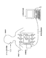
まず、図1は、本実施の形態1に係るカプセル型内視鏡システムの概略構成を示す模式図である。図1に示すように、このカプセル型内視鏡システムは、被検体1の体内画像を撮像するカプセル型内視鏡2と、被検体1の内部に導入されたカプセル型内視鏡2から送信された被検体1の体内画像を受信する受信装置3と、受信装置3が受信した被検体1の体内画像を表示する画像表示装置4と、受信装置3と画像表示装置4との間のデータの受け渡しを行うための携帯型記録媒体5とを備える。
(Embodiment 1)
First, FIG. 1 is a schematic diagram illustrating a schematic configuration of a capsule endoscope system according to the first embodiment. As shown in FIG. 1, this capsule endoscope system transmits from a
カプセル型内視鏡2は、被検体1の口から飲込まれた後、臓器の蠕動運動等によって被検体1の臓器内部を移動しつつ、被検体1の体内画像を順次撮像する。また、カプセル型内視鏡2は、被検体1の体内画像を撮像する都度、撮像した体内画像を含む撮像情報を外部の受信装置3に対して順次無線送信する。この場合、カプセル型内視鏡2は、自身の持つ固有の機能に対応する時間間隔で被検体1の各体内画像を順次無線送信する。
After being swallowed from the mouth of the subject 1, the
受信装置3は、カプセル型内視鏡2が撮像した被検体1の体内画像群を受信し、受信した体内画像群を蓄積する。具体的には、受信装置3は、複数の受信アンテナ3a〜3hを有し、臓器内部にカプセル型内視鏡2を導入する被検体1に装着(携帯)される。この受信装置3は、被検体1内部のカプセル型内視鏡2が無線送信した撮像情報を複数の受信アンテナ3a〜3hを介して順次受信し、被検体1の体内画像群を取得する。また、受信装置3は、着脱可能に挿着される携帯型記録媒体5を有し、カプセル型内視鏡2から取得した被検体1の体内画像群を携帯型記録媒体5に記録する。
The
受信アンテナ3a〜3hは、例えば被検体1の臓器内部に導入されたカプセル型内視鏡2の移動経路(すなわち被検体1の消化管)に沿って被検体1の体表上に分散配置され、上述した受信装置3に接続される。受信アンテナ3a〜3hは、被検体1内部のカプセル型内視鏡2が順次無線送信した撮像情報を捕捉し、この補足した撮像情報を受信装置3に対して順次送出する。なお、受信アンテナ3a〜3hは、被検体1に着用させるジャケット等に分散配置されてもよい。また、撮像情報を捕捉する受信アンテナは、被検体1に対して1以上配置されればよく、その配置数は、特に8つに限定されない。
The
ここで、受信装置3は、複数の受信アンテナ3a〜3hによって受信したRF信号を復調し、この復調された信号をもとに画像情報などを生成して携帯型記録媒体5に記憶する。受信装置3は、受信したRF信号の受信電界強度をもとに、最も受信電界強度が高い受信アンテナ3a〜3hを選択し、この選択した受信アンテナを介して取得された画像情報を携帯型記録媒体5に記録する。受信装置3は、各種の指示情報などを入力し、あるいは出力する手段として、例えばタッチパネルなどを備えてもよい。
Here, the
画像表示装置4は、携帯型記録媒体5を媒介して被検体1の体内画像群等の各種データを取得し、この取得した各種データをディスプレイ上に表示するワークステーション等のような構成を有する。具体的には、画像表示装置4は、被検体1の体内画像群等が記録された携帯型記録媒体5を着脱可能に挿着し、この挿着した携帯型記録媒体5から被検体1の体内画像群等を取り込む。この場合、画像表示装置4は、上述した受信装置3によってカプセル型内視鏡2固有の機能別に識別された状態の体内画像群を取得する。画像表示装置4は、このように取得した体内画像群をカプセル型内視鏡2固有の機能別に保持管理し、カプセル型内視鏡2固有の機能別に区別した態様で各体内画像を表示する。このように画像表示装置4が被検体1の各体内画像を区別して表示することによって、医師または看護師等のユーザは、容易且つ効率的に被検体1の各体内画像を観察(検査)できる。なお、ユーザは、かかる画像表示装置4が表示した被検体1の各体内画像を観察して、被検体1を診断する。
The image display device 4 has a configuration such as a workstation that acquires various data such as an in-vivo image group of the subject 1 through the
携帯型記録媒体5は、可搬型の記録媒体であり、上述した受信装置3と画像表示装置4との間のデータの受け渡しを行うためのものである。具体的には、携帯型記録媒体5は、受信装置3および画像表示装置4に対して着脱可能であって、両者に対する挿着時にデータの出力および記録が可能な構造を有する。このような携帯型記録媒体5は、受信装置3に挿着された場合、受信装置3がカプセル型内視鏡2から受信した被検体1の体内画像群等を記録し、画像表示装置4に挿着された場合、被検体1の体内画像群等の記録データを画像表示装置4に送出する。
The
なお、携帯型記録媒体5が記録する各種データは、例えば、被検体1の体内画像群、これら体内画像群内の各体内画像の時間情報(撮像時刻、受信時刻等)、被検体1の患者情報、被検体1の検査情報、撮像情報等である。ここで、被検体1の患者情報は、被検体1を特定する特定情報であり、例えば、被検体1の患者名、患者ID、生年月日、性別、年齢等である。また、被検体1の検査情報は、被検体1に対して実施されるカプセル型内視鏡検査(臓器内部にカプセル型内視鏡2を導入して臓器内部を観察するための検査)を特定する特定情報であり、例えば、検査ID、検査日等である。また、撮像情報とは、後述する撮像対象が、平面調光設定の照明光により撮像されたものであるか、筒状調光設定の照明光により撮像されたものであるかなどの撮像時の調光設定を示す情報である。
The various data recorded by the
図2は、本実施の形態1に係るカプセル型内視鏡の構成を示すブロック図である。カプセル型内視鏡2は、筐体に覆われる。筐体は、被検体1の内部に導入し易い大きさに形成されたカプセル型の筐体であり、筒状のケース本体10aと光学ドーム10bとによって形成される(図4参照)。ケース本体10aは、一端が開口し且つ他端がドーム状に閉じた筒状構造を有するケース部材である。光学ドーム10bは、ドーム状に形成された透明な光学部材であり、ケース本体10aの一端である開口端を閉じる態様でケース本体10aに取り付けられる。かかるケース本体10aと光学ドーム10bとによって形成される筐体は、カプセル型内視鏡2の各構成部を液密に収容する。
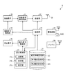
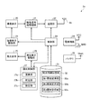
FIG. 2 is a block diagram showing a configuration of the capsule endoscope according to the first embodiment. The
カプセル型内視鏡2は、撮像素子20、画像信号処理回路21、送信部22、送信アンテナ23、撮像素子駆動部24、発光素子25、発光素子駆動部26、調光制御部27、電源回路28、バッテリ29、制御部30、記憶部31を有する。本発明にかかる照明部は、発光素子25および発光素子駆動部26により構成される。
The
撮像素子20は、CMOSイメージセンサまたはCCD等の固体撮像素子を用いて実現される。撮像素子20は、撮像視野からの反射光を、撮像面を介して受光し、この受光した光を光電変換処理して、この撮像視野の被写体画像、すなわち被検体1の体内画像を撮像する。また、撮像素子20の受光面側には、レンズ20aが設けられている(図3、4参照)。
The
画像信号処理回路21は、画像信号を生成する信号処理機能を有する。画像信号処理回路21は、撮像素子20から体内画像データを取得し、その都度、この体内画像データに対して所定の信号処理を行って、体内画像データを含む画像信号を生成する。
The image signal processing circuit 21 has a signal processing function for generating an image signal. The image signal processing circuit 21 acquires in-vivo image data from the
送信部22は、画像信号処理回路21から出力された画像信号を含む撮像情報に対して変調処理等を行って、この画像信号を変調した無線信号を生成し、送信アンテナ23を介して、該生成した無線信号を外部に出力する。
The
撮像素子駆動部24は、制御部30からの駆動信号に基づいて、撮像素子20の駆動を制御する。撮像素子20、画像信号処理回路21および撮像素子駆動部24は撮像部として機能する。
The image
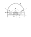
ここで、照明部および撮像部の詳細構成について説明する。図3は、本実施の形態1に係るカプセル型内視鏡の要部の構成を示す平面図であって、カプセル型内視鏡内の発光素子25の配列状態を光学ドーム側からみた図である。図4は、図3に示すA−A線断面を示す部分断面図であって、照明部および撮像部が配置される近傍の縦断面図である。図3に示すように、発光素子25は、撮像素子20およびレンズ20aの周りに、複数の発光素子が等間隔で配列される。発光素子25は、第1発光素子LA1、第2発光素子LA2、第3発光素子LA3および第4発光素子LA4からなる4つの発光素子を有し、光源基板25a上に配置される。ここで、第1発光素子LA1は第3発光素子LA3とレンズ20aを介して対向し、第2発光素子LA2は第4発光素子LA4とレンズ20aを介して対向している。
Here, detailed configurations of the illumination unit and the imaging unit will be described. FIG. 3 is a plan view showing a configuration of a main part of the capsule endoscope according to the first embodiment, and is a view of the arrangement state of the
第1発光素子LA1、第2発光素子LA2、第3発光素子LA3および第4発光素子LA4は、白色の照明光を発光する白色光源である。なお、発光素子ごとにピーク波長が異なるものとしてもよいし、出射する照明光の波長帯域が異なるものとしてもよい。 The first light emitting element LA1, the second light emitting element LA2, the third light emitting element LA3, and the fourth light emitting element LA4 are white light sources that emit white illumination light. The peak wavelength may be different for each light emitting element, or the wavelength band of the emitted illumination light may be different.
第1発光素子LA1、第2発光素子LA2、第3発光素子LA3および第4発光素子LA4は、撮像素子20の撮像視野の中心が最も明るくなるように向きなどが調整されている。このため、撮像素子20により平面の被写体を撮像すると、得られる測光値(輝度値)は画像の中心の測光値が最も大きくなる。
The orientation of the first light emitting element LA1, the second light emitting element LA2, the third light emitting element LA3, and the fourth light emitting element LA4 is adjusted so that the center of the imaging field of the
レンズ20aは、鏡筒20b内であって撮像素子20の上部に配置される。レンズ20aは、発光素子25から照射され、被写体から反射した光を集光し、撮像素子20上に結像させる。鏡筒20bおよび撮像素子20は、撮像基板20c上に配置固定される。
The
発光素子駆動部26は、調光制御部27からの制御信号に基づいて発光素子25を駆動する。具体的には、発光素子駆動部26は、制御信号に基づいて第1発光素子LA1、第2発光素子LA2、第3発光素子LA3および第4発光素子LA4に供給する電力を制御して、各発光素子が発する光量や発光時間などを制御する。
The light emitting element driving unit 26 drives the
調光制御部27は、撮像素子20により得られた体内画像データの演算結果をもとに、撮像した画像が、胃壁などの平面の被写体を撮像したものであるか、管腔(例えば小腸)などの筒状の被写体を撮像したものであるかを判定し、判定した被写体の形状に応じた照明光の調光モードを設定し、該調光モードを含む制御信号を発光素子駆動部26に出力する。
Based on the calculation result of the in-vivo image data obtained by the
調光制御部27は、演算部27a、判定部27bおよび設定部27cを有する。演算部27aは、体内画像データの画像表示領域において設定された複数の測光エリアにおける複数の測光ポイントの測光値(輝度値)を規格化した規格化測光値を算出し、複数の規格化測光値の平均値を算出して測光エリアの代表規格化測光値を演算する。
The dimming
図5は、本実施の形態1に係るカプセル型内視鏡が行う調光処理における測光エリア設定を説明する図である。本実施の形態では、図5に示す画像表示領域100に対し、同心円状の測光エリアである円周エリアEc1〜Ec4が設定されるとともに、各円周エリアにおいて、複数の測光ポイントがそれぞれ等間隔に設定されている。具体的には、円周エリアEc1は、測光ポイントEp11〜Ep18が設定されている。円周エリアEc2は、測光ポイントEp21〜Ep28が設定されている。円周エリアEc3は、測光ポイントEp31〜Ep38が設定されている。円周エリアEc4は、測光ポイントEp41〜Ep48が設定されている。
FIG. 5 is a diagram for explaining photometry area setting in the light control processing performed by the capsule endoscope according to the first embodiment. In the present embodiment, circumferential areas Ec1 to Ec4 that are concentric photometric areas are set for the
演算部27aは、得られた体内画像データをもとに、各測光ポイントの測光値を規格化して規格化測光値として算出し、円周エリアEc1〜Ec4ごとに複数の規格化測光値の平均値を求めて、該平均値を代表規格化測光値として出力する。その後、演算部27aは、記憶部31に記憶されている円周エリアEc1〜Ec4ごとの平面調光目標値と、代表規格化測光値との差分値を算出する。なお、規格化測光値は、各測光ポイントの互いの最大値および最小値をそれぞれ同じ値とする規格化された値である。
Based on the obtained in-vivo image data, the
判定部27bは、円周エリアEc1〜Ec4の各測光ポイントEp11〜Ep48の測光値に基づく値と、第1閾値記憶部32aおよび第2閾値記憶部32bに記憶されている閾値とをもとに、撮像された被写体に対して平面調光および筒状調光のいずれを行うかを判定する。また、判定部27bは、平面調光および筒状調光の各設定において、壁面が近接していない単純調光を行うか、壁面が近接している壁面近接調光を行うかを判定する。
The
設定部27cは、判定部27bの判定結果に基づいて調光モードを設定し、該調光モードで発光素子25が駆動するための制御信号を生成し、発光素子駆動部26に出力する。
The
バッテリ29は、電池などによって実現される。電源回路28は、このバッテリ29を用いて各構成部に電源を供給する。
The
制御部30は、カプセル型内視鏡2の構成部の各動作を制御し、かつ、かかる各構成部間における信号の入出力を制御する。具体的には、制御部30は、被写体の画像を撮像素子20に撮像させる制御を行う。また、制御部30は、画像信号処理回路21から出力された画像信号を含む撮像情報を時系列に沿って外部に順次無線送信するように送信部22を制御する。
The
記憶部31は、フラッシュメモリ等の半導体メモリ等によって実現される。記憶部31は、制御部30が記憶指示した各種情報を記憶し、記憶した各種情報の中から制御部30が読み出し指示した情報を制御部30に送出する。なお、かかる記憶部31が記憶する各種情報として、例えば、カプセル型内視鏡2が動作するためのプログラムや、カプセル型内視鏡2による撮像条件(例えばフレームレート)、照明光の調光モードにかかる情報などが挙げられる。
The storage unit 31 is realized by a semiconductor memory such as a flash memory. The storage unit 31 stores various types of information instructed to be stored by the
また、記憶部31は、配光情報を記憶する配光情報記憶部32を有する。配光情報は、予め胃壁などに対応する平面の被写体を撮像して得られた測光値、および予め管腔(例えば小腸)などに対応する筒状の被写体を撮像して得られた測光値を含むチャート(受光輝度分布)、平面調光の目標値を円周エリアEc1〜Ec4ごとに設定した平面調光目標値、ならびに筒状調光の目標値を円周エリアEc1〜Ec4ごとに設定した筒状調光目標値を含む。例えば、平面調光目標値は、平面の被写体を撮像した際の円周エリアEc1〜Ec4ごとの明るさに応じた値であって規格化された値である。調光目標値は、実測値を用いて求めてもよいし、設計値を用いて求めてもよい。
The storage unit 31 includes a light distribution
配光情報記憶部32は、上述したチャートに基づいて設定された閾値を記憶する第1閾値記憶部32aおよび第2閾値記憶部32bを有する。第1閾値記憶部32aは、平面の被写体を撮像して得られたチャートに基づいて設定された各種閾値を記憶する。また、第2閾値記憶部32bは、筒状の被写体を撮像して得られたチャートに基づいて設定された閾値を記憶する。
The light distribution
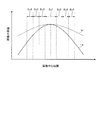
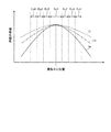
図6は、異なる形状の被写体を撮像した際に得られる受光輝度分布を説明する図である。図6に示すグラフは、撮像中心を通過する直線上の位置と、異なる被写体を撮像して得られた輝度の最大値が等しくなるように輝度曲線を規格化した規格化輝度との関係を示す。図6において、曲線Lpは平面状の被写体により得られた輝度曲線を示し、曲線Lrは筒状の被写体により得られた輝度曲線を示す。 FIG. 6 is a diagram for explaining the received light luminance distribution obtained when images of subjects having different shapes are imaged. The graph shown in FIG. 6 shows the relationship between the position on the straight line passing through the imaging center and the normalized luminance obtained by standardizing the luminance curve so that the maximum luminance values obtained by imaging different subjects are equal. . In FIG. 6, a curve Lp indicates a luminance curve obtained with a planar object, and a curve Lr indicates a luminance curve obtained with a cylindrical object.
図6に示すように、平面状および筒状の被写体により得られた各輝度曲線は、ピーク位置(撮像中心位置)から離れるにしたがって、輝度値が低下する。ここで、平面状の被写体による受光輝度分布は、筒状の被写体による受光輝度分布に比べて、撮像中心位置の輝度と、撮像中心位置から離れた位置での輝度との差が大きい。図6に示すように、円周エリアEc1〜Ec4ごとにみると、撮像中心位置に近い円周エリア(例えば円周エリアEc1)よりも、撮像中心から離れた円周エリア(例えば円周エリアEc4)の方が、平面状の輝度と筒状の輝度との差が大きい。 As shown in FIG. 6, the luminance value of each luminance curve obtained by the planar and cylindrical subjects decreases as the distance from the peak position (imaging center position) increases. Here, the light reception luminance distribution by the planar subject has a larger difference between the luminance at the imaging center position and the luminance at the position away from the imaging center position than the light reception luminance distribution by the cylindrical subject. As shown in FIG. 6, in each of the circumferential areas Ec1 to Ec4, a circumferential area (for example, the circumferential area Ec4) that is farther from the imaging center than a circumferential area (for example, the circumferential area Ec1) that is closer to the imaging center position. ) Has a larger difference between the planar luminance and the cylindrical luminance.
第1閾値記憶部32aは、平面の被写体を撮像して得られた測光値と平面調光目標値との差分の基準値を円周エリアEc1〜Ec4ごとに定め、各々規格化した円周エリアEc1〜Ec4の基準差分値と、差分値が基準差分値を超えた測定ポイントの数を規定した閾値であって、被写体が平面であるか否かを判断するための閾値である平面判定値と、平面調光において、壁面が近接しているか否かを判定するための第1壁面近接判定値と、を記憶する。第1壁面近接判定値は、差分値が基準差分値を超えた測定ポイントに隣接する四つの測定ポイントのうち基準差分値を超えている測定ポイントの数を規定した値である。各判定値は、例えば全測定ポイントの過半数に設定される。
The first threshold
第2閾値記憶部32bは、差分値が基準差分値を超えた測定ポイントに隣接する四つの測定ポイントのうち基準差分値を超えている測定ポイントの数を規定した値であって、筒状調光において、壁面が近接しているか否かを判定するための第2壁面近接判定値を記憶する。
The second threshold
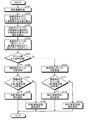
図7は、本発明の一実施の形態に係るカプセル型内視鏡の調光制御部27が行う調光処理を示すフローチャートである。まず、調光制御部27は、配光情報を取得する(ステップS101)。具体的には、調光制御部27は、配光情報記憶部32を参照して、上述した平面調光目標値等の配光情報を取得する。
FIG. 7 is a flowchart showing the light control processing performed by the
続いて、調光制御部27は、撮像素子20により生成された撮像信号をもとに、各測光ポイントEp11〜Ep48の代表規格化測光値を取得する(ステップS102)。具体的には、演算部27aが、各測光ポイントEp11〜Ep48にそれぞれ含まれる画素の画素値(測光値)を規格化し、平均値を求めて代表規格化測光値とする。演算部27aは、例えば、測光ポイントEp11に含まれる複数の画素の画素値(測光値)を規格化し、規格化された複数の規格化測光値の平均値を算出して、該算出された平均値を測光ポイントEp11の代表規格化測光値とする。同様にして、測光ポイントEp12〜Ep48についてもそれぞれ代表規格化測光値を求める。
Subsequently, the dimming
演算部27aは、測光ポイントEp11〜Ep48ごとに算出された代表規格化測光値と、平面調光目標値との差分(差分値)を算出する(ステップS103)。具体的には、演算部27aは、各円周エリアEc1〜Ec4のいずれかのエリアにある測光ポイントEp11〜Ep48の代表規格化測光値と、円周エリアEc1〜Ec4ごとに設定された平面調光目標値と、の差分値を算出する。例えば、円周エリアEc1にある測光ポイントEp11と、円周エリアEc1の平面調光目標値との差分を算出し、該算出した差分値を出力する。同様にして、測光ポイントEp12〜Ep48についてもそれぞれ差分値を算出する。
The calculating
調光制御部27は、演算部27aから測光ポイントEp11〜Ep48の各差分値が出力されると、差分値と閾値(基準差分値)とを比較して、閾値を越えた差分値の数(測光ポイントの数)をカウントする(ステップS104)。具体的には、判定部27bが、各差分値と基準差分値とを比較し、差分値が基準差分値を超えているか否かを判定する。判定部27bは、基準差分値を超えている差分値を有する測光ポイントを抽出し、抽出した測光ポイントをカウントする。
When the
その後、判定部27bは、カウント数が、平面判定値以下であるか否かを判定する(ステップS105)。ここで、調光制御部27は、判定部27bによりカウント数が平面判定値以下であると判定された場合(ステップS105:Yes)、ステップS106に移行して平面調光設定における隣接測光ポイント判定処理を行う。
Thereafter, the
調光制御部27は、ステップS106に移行すると、ステップS104で抽出された測光ポイントについて、隣接する測光ポイントが基準差分値を超えているか否かを判定する。具体的には、判定部27bが、抽出された測光ポイントごとに、隣接する測光ポイント(以下、隣接測光ポイントともいう)が基準差分値を超えているか否かを判定する。例えば、測光ポイントEp23が抽出された場合、判定部27bは、隣接する四つの測光ポイントEp13,Ep22,Ep24,Ep33について、それぞれが基準差分値を超えているか否かを判定する。
When the dimming
判定部27bは、抽出された測光ポイントに隣接する隣接測光ポイントのうち、基準差分値を超えている隣接測光ポイントの数が第1壁面近接判定値以下であるか否かを判断する(ステップS107)。ここで、第1壁面近接判定値は、平面状の被写体において壁面に近接しているか否かを判定するための隣接測光ポイント数を規定した値である。
The
判定部27bにより隣接測光ポイント数が第1壁面近接判定値以下であると判定された場合(ステップS107:Yes)、設定部27cは、平面(単純平面)調光に設定し、該設定した調光モードの制御信号を生成して発光素子駆動部26に出力する(ステップS108)。単純平面調光設定では、第1発光素子LA1、第2発光素子LA2、第3発光素子LA3および第4発光素子LA4の発光量を一定とし、被写体に対して均一な照明光が照射される。
When the
これに対し、判定部27bにより隣接測光ポイント数が第1壁面近接判定値を超えていると判定された場合(ステップS107:No)、設定部27cは、平面(壁面近接)調光に設定し、該設定した調光モードの制御信号を生成して発光素子駆動部26に出力する(ステップS109)。壁面近接調光設定では、上述した単純平面の調光設定に対して、第1発光素子LA1、第2発光素子LA2、第3発光素子LA3および第4発光素子LA4のうち、第1壁面近接判定値を超えていると判定された測光ポイントに近接する発光素子の発光量を低減することで、カプセル型内視鏡2に近接する壁面に照射される照明光の光量が低減される。なお、壁面は、ある一つの方向に存在するもののみならず、複数の方向(例えばカプセル型内視鏡2の右方向および上方向など)に壁面が存在する場合もある。
On the other hand, when the
一方、調光制御部27は、判定部27bによりカウント数が平面判定値を超えていると判定された場合(ステップS105:No)、ステップS110に移行して筒状調光設定における隣接測光ポイント判定処理を行う。
On the other hand, when it is determined by the
ステップS110では、演算部27aが、上述したステップS102〜S104と同様に、測光ポイントEp11〜Ep48ごとに算出された代表規格化測光値と、筒状調光目標値との差分(差分値)を算出し、判定部27bが、差分値と閾値(基準差分値)とを比較して、閾値を越えた差分値(測光ポイント)を抽出する。
In step S110, the
判定部27bは、抽出された測光ポイントに隣接する隣接測光ポイントのうち、基準差分値を超えている隣接測光ポイント数が第2壁面近接判定値以下であるか否かを判断する(ステップS111)。ここで、第2壁面近接判定値は、筒状の被写体において壁面に近接しているか否かを判定するための隣接測光ポイント数を規定した値である。
The
判定部27bにより隣接測光ポイント数が第2壁面近接判定値以下であると判定された場合(ステップS111:Yes)、設定部27cは、筒状(単純筒状)調光に設定し、該設定した調光モードの制御信号を生成して発光素子駆動部26に出力する(ステップS112)。単純筒状調光設定では、第1発光素子LA1、第2発光素子LA2、第3発光素子LA3および第4発光素子LA4の発光量を一定とし、かつ単純平面調光設定よりも光量を小さくする。
When the
これに対し、判定部27bにより隣接ポイント数が第2壁面近接判定値を超えていると判定された場合(ステップS111:No)、設定部27cは、筒状(壁面近接)調光に設定し、該設定した調光モードの制御信号を生成して発光素子駆動部26に出力する(ステップS113)。壁面近接調光設定では、上述した単純筒状の調光設定に対して、第1発光素子LA1、第2発光素子LA2、第3発光素子LA3および第4発光素子LA4のうち、第2壁面近接判定値を超えていると判定された測光ポイントに対して照明光を照射する発光素子の発光量を低減することで、カプセル型内視鏡2に近接する壁面に照射される照明光の光量が低減される。
On the other hand, when the
上述した本実施の形態1によれば、演算部27aが、撮像画像を同心円状に分割した複数の測光エリアにおいて設定された複数の測光ポイントにおける代表測光値と、複数の測光エリアごとに設定される目標測光値と、の差分を算出し、判定部27bが、該差分と、複数の測光エリアごとに設定される閾値と、を比較し、該比較結果に基づいて被写体が平面状をなすか、筒状をなすかを判定し、設定部27cが、判定部27bの判定結果に基づいて、平面調光設定、または筒状調光設定のいずれかを設定し、該設定した調光設定にかかる制御信号を発光素子駆動部26に出力するようにしたので、被写体の形状(平面状、または筒状)に対応して最適な照明を行うことができる。
According to the first embodiment described above, the
また、上述した本実施の形態1によれば、判定部27b被写体が平面状をなすか、または筒状をなすかを判定した後に、カプセル型内視鏡2(撮像素子20)が被写体の壁面と近接しているか否かを判定し、設定部27cが、判定部27bの判定結果に基づいて、壁面と近接していない単純調光設定、または壁面に近接した壁面近接調光設定のいずれかを設定するようにしたので、被写体の形状をより詳細に判定し、シーンに適した照明制御を行うことができる。
In addition, according to the first embodiment described above, the
(実施の形態2)
続いて、本発明の実施の形態2について説明する。図8は、本実施の形態2に係るカプセル型内視鏡の構成を示すブロック図である。なお、上述した構成と同一の構成には同一の符号を付して説明する。上述した実施の形態1では、被写体の形状を平面状または筒状のいずれであるかを判定するものとして説明したが、本実施の形態2では、被写体の形状を平面状、筒状、球状のいずれであるかを判定する。なお、球状とは、半球状や楕円状を含む。
(Embodiment 2)
Next, a second embodiment of the present invention will be described. FIG. 8 is a block diagram showing a configuration of the capsule endoscope according to the second embodiment. In addition, the same code | symbol is attached | subjected and demonstrated to the structure same as the structure mentioned above. In the first embodiment described above, it has been described as determining whether the shape of the subject is planar or cylindrical. However, in the second embodiment, the shape of the subject is planar, cylindrical, or spherical. It is determined which one. The spherical shape includes a hemispherical shape and an elliptical shape.
本実施の形態2に係るカプセル型内視鏡2aは、配光情報記憶部32が、球状調光の目標値を円周エリアEc1〜Ec4ごとに設定した球状調光目標値をさらに記憶するとともに、球状の被写体を撮像して得られたチャートに基づいて設定された各種閾値を記憶する第3閾値記憶部32cをさらに有する。また、第1閾値記憶部32aは、円周エリアのカウント数を規定した閾値であって、被写体が平面であるか否かを判断するための閾値である第2平面判定値をさらに記憶する。
In the
第3閾値記憶部32cは、差分値が基準差分値を超えた測定ポイントの数を規定した閾値であって、被写体が球状であるか否かを判断するための閾値である球状判定値と、隣接測定ポイントのうち基準差分値を超えている隣接測定ポイントの数を規定した値であって、球状調光において、壁面が近接しているか否かを判定するための第3壁面近接判定値と、を記憶する。
The third threshold
図9は、異なる形状の被写体を撮像した際に得られる受光輝度分布を説明する図である。図9に示すグラフは、撮像中心を通過する直線上の位置と、異なる被写体を撮像して得られた輝度の最大値が等しくなるように輝度曲線を規格化した規格化輝度との関係を示す。図9では、上述した曲線LpおよびLrに加え、球状の被写体により得られた輝度曲線である曲線Lbを示している。 FIG. 9 is a diagram for explaining a received light luminance distribution obtained when images of subjects having different shapes are picked up. The graph shown in FIG. 9 shows the relationship between the position on the straight line passing through the imaging center and the normalized luminance obtained by normalizing the luminance curve so that the maximum luminance values obtained by imaging different subjects are equal. . In FIG. 9, in addition to the above-described curves Lp and Lr, a curve Lb which is a luminance curve obtained by a spherical subject is shown.
図9に示すように、球状の被写体により得られた輝度曲線では、ピーク位置(撮像中心位置)から離れるにしたがって、輝度値が低下する。ここで、球状の被写体による受光輝度分布は、平面状の被写体による受光輝度分布に比べて、撮像中心位置の輝度と、撮像中心位置から離れた位置での輝度との差が小さい。 As shown in FIG. 9, in the luminance curve obtained from a spherical subject, the luminance value decreases as the distance from the peak position (imaging center position) increases. Here, the light reception luminance distribution by the spherical subject has a smaller difference between the luminance at the imaging center position and the luminance at the position away from the imaging center position than the light reception luminance distribution by the planar subject.
図10は、本実施の形態2に係るカプセル型内視鏡が行う調光処理を示すフローチャートである。調光制御部27は、上述したステップS101,S102と同様に、配光情報を取得し(ステップS201)、撮像素子20により生成された撮像信号をもとに、各測光ポイントEp11〜Ep48の代表規格化測光値を取得する(ステップS202)。その後、演算部27aが、上述したステップS103〜S105と同様に、測光ポイントEp11〜Ep48ごとに算出された代表規格化測光値と、平面調光目標値との差分(差分値)を算出し(ステップS203)、判定部27bが、差分値と閾値(基準差分値)とを比較して、閾値を越えた差分値(測光ポイント)を抽出してカウントし(ステップS204)、カウント数が、平面判定値以下であるか否かを判定する(ステップS205)。
FIG. 10 is a flowchart showing the light control processing performed by the capsule endoscope according to the second embodiment. The dimming
ここで、調光制御部27は、判定部27bによりカウント数が平面判定値以下であると判定された場合(ステップS205:Yes)、ステップS206に移行して平面調光設定における隣接測光ポイント判定処理を行う。判定部27bは、ステップS206に移行すると、ステップS204で抽出された測光ポイントについて、隣接測光ポイントが基準差分値を超えているか否かを判定する。その後、判定部27bが、隣接測光ポイントのうち、基準差分値を超えている隣接測光ポイント数が第1壁面近接判定値以下であるか否かを判断する(ステップS207)。
Here, if the
判定部27bにより隣接測光ポイント数が第1壁面近接判定値以下であると判定された場合(ステップS207:Yes)、設定部27cは、平面(単純平面)調光に設定し、該設定した調光モードの制御信号を生成して発光素子駆動部26に出力する(ステップS208)。
When the
これに対し、判定部27bにより隣接測光ポイント数が第1壁面近接判定値を超えていると判定された場合(ステップS207:No)、設定部27cは、平面(壁面近接)調光に設定し、該設定した調光モードの制御信号を生成して発光素子駆動部26に出力する(ステップS209)。
On the other hand, when the
一方、調光制御部27は、判定部27bによりカウント数が平面判定値を超えていると判定された場合(ステップS205:No)、ステップS210に移行して円周エリア判定処理を行う。
On the other hand, if the
ステップS210では、演算部27aが、円周エリアEc1〜Ec4の測光ポイントの代表規格化測光値の平均値を算出する。その後、判定部27bが、この円周エリアEc1〜Ec4ごとの平均値と、各円周エリアの平面調光目標値とを比較して、平面調光目標値を超えた円周エリアの数をカウントする。
In step S210, the
判定部27bは、カウントした円周エリア数が、第2平面判定値以下であるか否かを判定する(ステップS211)。ここで、調光制御部27は、判定部27bにより円周エリア数が第2平面判定値以下であると判定された場合(ステップS211:Yes)、ステップS206に移行して平面調光設定における隣接測光ポイント判定処理を行う。
The
一方、調光制御部27は、判定部27bにより円周エリア数が第2平面判定値を超えていると判定された場合(ステップS211:No)、ステップS212に移行して放射状エリア判定処理を行う。
On the other hand, when it is determined by the
ステップS212では、演算部27aが、放射状エリアの測光ポイントに基づく放射状エリア判定処理を行う。演算部27aは、上述したステップS202〜S204と同様に、測光ポイントEp11〜Ep48ごとに算出された代表規格化測光値と、球状調光目標値との差分値を算出し、判定部27bが、差分値と基準差分値とを比較して、基準差分値を越えた差分値(測光ポイント)を抽出する。判定部27bは、抽出した測光ポイントが存在する放射状エリアの数をカウントする。
In step S212, the
次に、判定部27bは、カウントした放射状エリア数が、球状判定値以下であるか否かを判断する(ステップS213)。ここで、調光制御部27は、判定部27bにより放射状エリア数が球状判定値以下であると判定された場合(ステップS213:Yes)、ステップS214に移行して球状調光設定における隣接測光ポイント判定処理を行う。判定部27bは、ステップS214に移行すると、ステップS212で抽出された測光ポイントについて、隣接する測光ポイントの差分値が基準差分値を超えているか否かを判定する。その後、判定部27bが、抽出された測光ポイントに隣接する隣接測光ポイントのうち、基準差分値を超えている隣接測光ポイント数が第3壁面近接判定値以下であるか否かを判断する(ステップS215)。第3壁面近接判定値は、球状調光において、壁面が近接しているか否かを判定するための値である。
Next, the
判定部27bにより隣接測光ポイント数が第3壁面近接判定値以下であると判定された場合(ステップS215:Yes)、設定部27cは、球状(単純球状)調光に設定し、該設定した調光モードの制御信号を生成して発光素子駆動部26に出力する(ステップS216)。単純球状調光設定では、第1発光素子LA1、第2発光素子LA2、第3発光素子LA3および第4発光素子LA4の発光量を一定とするとともに、例えば、単純平面調光設定よりも光量を小さく、かつ筒状平面調光設定よりも光量を大きくする。
When the
これに対し、判定部27bにより隣接測光ポイント数が第3壁面近接判定値を超えていると判定された場合(ステップS215:No)、球状(壁面近接)調光に設定し、該設定した調光モードの制御信号を生成して発光素子駆動部26に出力する(ステップS217)。
On the other hand, when the
一方、調光制御部27は、判定部27bにより放射状エリア数が球状判定値より大きいと判定された場合(ステップS213:No)、ステップS218に移行して筒状調光設定における隣接測光ポイント判定処理を行う。
On the other hand, if the
ステップS218では、演算部27aが、上述したステップS202〜S204と同様に、測光ポイントEp11〜Ep48ごとに算出された代表規格化測光値と、筒状調光目標値との差分を算出し、判定部27bが、差分値と閾値(基準差分値)とを比較して、閾値を越えた差分値(測光ポイント)を抽出する。
In step S218, the
判定部27bは、抽出された測光ポイントに隣接する隣接測光ポイントのうち、基準差分値を超えている隣接測光ポイント数が第2壁面近接判定値以下であるか否かを判断する(ステップS219)。判定部27bにより隣接測光ポイント数が第2壁面近接判定値以下であると判定された場合(ステップS219:Yes)、設定部27cは、筒状(単純筒状)調光に設定し、該設定した調光モードの制御信号を生成して発光素子駆動部26に出力する(ステップS220)。
The
これに対し、判定部27bにより隣接測光ポイント数が第2壁面近接判定値を超えていると判定された場合(ステップS219:No)、設定部27cは、筒状(壁面近接)調光に設定し、該設定した調光モードの制御信号を生成して発光素子駆動部26に出力する(ステップS221)。
On the other hand, when the
上述した本実施の形態2によれば、演算部27aが、撮像画像を同心円状に分割した複数の測光エリアにおいて設定された複数の測光ポイントにおける代表測光値と、複数の測光エリアごとに設定される目標測光値と、の差分を算出し、判定部27bが、該差分と、複数の測光エリアごとに設定される閾値と、を比較し、該比較結果に基づいて被写体が平面状をなすか、球状をなすかを判定し、設定部27cが、判定部27bの判定結果に基づいて、平面調光設定、球状調光設定または筒状調光設定のいずれかを設定し、該設定した調光設定にかかる制御信号を発光素子駆動部26に出力するようにしたので、被写体の形状(平面状、球状または筒状)に対応して最適な照明を行うことができる。
According to the second embodiment described above, the
なお、上述した本実施の形態1,2では、平面調光を基本として判定処理を行って調光設定するものとして説明したが、筒状や球状を基本として判定処理を行うものであってもよい。 In the first and second embodiments described above, it has been described that the determination process is performed based on the plane dimming and the dimming is set. However, even if the determination process is performed based on the cylindrical shape or the spherical shape, Good.
また、上述した本実施の形態1,2では、各形状について、一つの判定値を用いるものとして説明したが、二つ以上の判定値(例えば、平面判定値が異なる二つの閾値)を用いて、それぞれ異なる調光設定を行うものとしてもよい。例えば、筒の径が異なる場合について複数の判定値を設け、それぞれ異なる光量となるようにしてもよい。この場合、筒の径が大きいほど得られる測光値は大きくなるため、径が小さいほど光量を小さくする調光設定となる。 Further, in the first and second embodiments described above, each shape is described as using one determination value, but two or more determination values (for example, two threshold values having different plane determination values) are used. Different dimming settings may be performed. For example, a plurality of determination values may be provided for cases where the diameters of the cylinders are different so that the light amounts are different from each other. In this case, since the photometric value obtained becomes larger as the diameter of the cylinder becomes larger, the dimming setting is made such that the light quantity becomes smaller as the diameter becomes smaller.
また、上述した本実施の形態1,2では、調光目標値が予め配光情報記憶部32に記憶されているものとして説明したが、測定の都度、調光目標値を算出するものであってもよい。
In the first and second embodiments described above, the dimming target value is described as being stored in advance in the light distribution
また、上述した本実施の形態1,2では、カプセル型内視鏡2,2aにおいて被写体の形状判定を行うものとして説明したが、受信装置3や画像処理装置4などカプセル型内視鏡の外部において形状判定処理および調光設定処理を行うものであってもよい。この場合、カプセル型内視鏡には、設定情報を出力する外部装置と無線通信を行うためのアンテナなどが設けられる。
In the first and second embodiments described above, the
以上のように、本発明にかかるカプセル型内視鏡は、被写体の形状を正確に判断するのに有用である。 As described above, the capsule endoscope according to the present invention is useful for accurately determining the shape of a subject.
1 被検体
2,2a カプセル型内視鏡
3 受信装置
4 画像表示装置
5 携帯型記録媒体
20 撮像素子
21 画像信号処理回路
22 送信部
23 送信アンテナ
24 撮像素子駆動部
25 発光素子
26 発光素子駆動部
27 調光制御部
27a 演算部
27b 判定部
27c 設定部
28 電源回路
29 バッテリ
30 制御部
31 記憶部
32 配光情報記憶部
32a 第1閾値記憶部
32b 第2閾値記憶部
32c 第3閾値記憶部
DESCRIPTION OF SYMBOLS 1
Claims (4)
被写体に照明する照明光を出射する照明部と、
前記被写体の形状に応じた前記撮像素子の受光輝度分布に基づく配光情報を記憶する配光情報記憶部と、
前記撮像信号に基づく撮像画像を同心円状に分割した複数の測光エリアにおいて設定された複数の測光ポイントにおける代表測光値と、前記配光情報記憶部に記憶され、複数の測光エリアごとに設定される目標測光値と、の差分を算出する演算部と、
前記差分値と、前記配光情報記憶部に記憶され、複数の測光エリアごとに設定される基準差分値とを比較し、該基準差分値を超えた前記差分値をカウントして、該カウントされた数と、前記配光情報記憶部に記憶され、前記被写体の形状を判定する形状判定値と、を比較して、前記被写体の形状を判定するための判定結果を生成する判定部と、
前記判定部の判定結果に基づいて前記被写体の形状を判定し、該判定した前記被写体の形状に応じた調光設定を行って、該調光設定にかかる制御信号を前記照明部に出力する設定部と、
を備えたことを特徴とするカプセル型内視鏡。 An image sensor that photoelectrically converts received light and generates the converted electrical signal as an imaging signal;
An illumination unit that emits illumination light to illuminate the subject;
A light distribution information storage unit that stores light distribution information based on a light-receiving luminance distribution of the image sensor according to the shape of the subject;
Representative photometric values at a plurality of photometry points set in a plurality of photometry areas obtained by concentrically dividing a captured image based on the image pickup signal, and stored in the light distribution information storage unit, are set for each of the plurality of photometry areas. A calculation unit for calculating a difference between the target metering value and
The difference value is stored in the light distribution information storage unit and compared with a reference difference value set for each of a plurality of light metering areas, and the difference value exceeding the reference difference value is counted and counted. A determination unit that generates a determination result for determining the shape of the subject by comparing the number and a shape determination value that is stored in the light distribution information storage unit and determines the shape of the subject;
Setting that determines the shape of the subject based on the determination result of the determination unit, performs dimming setting according to the determined shape of the subject, and outputs a control signal related to the dimming setting to the illumination unit And
A capsule endoscope characterized by comprising:
前記設定部は、前記判定部の判定結果に基づいて、前記壁面と近接していない単純調光設定、または前記壁面に近接した壁面近接調光設定のいずれかを設定する
ことを特徴とする請求項1に記載のカプセル型内視鏡。 The determination unit determines whether the imaging element is close to the wall surface of the subject after determining the shape of the subject,
The setting unit is configured to set either a simple dimming setting that is not close to the wall surface or a near wall dimming setting that is close to the wall surface based on a determination result of the determination unit. Item 2. The capsule endoscope according to Item 1.
Priority Applications (1)
| Application Number | Priority Date | Filing Date | Title |
|---|---|---|---|
| JP2015005174A JP2016129618A (en) | 2015-01-14 | 2015-01-14 | Capsule type endoscope |
Applications Claiming Priority (1)
| Application Number | Priority Date | Filing Date | Title |
|---|---|---|---|
| JP2015005174A JP2016129618A (en) | 2015-01-14 | 2015-01-14 | Capsule type endoscope |
Publications (2)
| Publication Number | Publication Date |
|---|---|
| JP2016129618A true JP2016129618A (en) | 2016-07-21 |
| JP2016129618A5 JP2016129618A5 (en) | 2017-11-30 |
Family
ID=56414953
Family Applications (1)
| Application Number | Title | Priority Date | Filing Date |
|---|---|---|---|
| JP2015005174A Pending JP2016129618A (en) | 2015-01-14 | 2015-01-14 | Capsule type endoscope |
Country Status (1)
| Country | Link |
|---|---|
| JP (1) | JP2016129618A (en) |
Cited By (2)
| Publication number | Priority date | Publication date | Assignee | Title |
|---|---|---|---|---|
| WO2019225691A1 (en) * | 2018-05-23 | 2019-11-28 | オリンパス株式会社 | Endoscope image processing device and endoscope system |
| WO2022059282A1 (en) * | 2020-09-17 | 2022-03-24 | 株式会社Jvcケンウッド | Imaging control device, endoscope system, and imaging control method |
Citations (4)
| Publication number | Priority date | Publication date | Assignee | Title |
|---|---|---|---|---|
| JP2010005129A (en) * | 2008-06-26 | 2010-01-14 | Olympus Medical Systems Corp | Capsule light source device, and internal body image obtaining system using the same |
| JP2010017231A (en) * | 2008-07-08 | 2010-01-28 | Olympus Medical Systems Corp | Capsule type medical device |
| WO2010143692A1 (en) * | 2009-06-10 | 2010-12-16 | オリンパスメディカルシステムズ株式会社 | Capsule type endoscope device |
| JP2012147882A (en) * | 2011-01-18 | 2012-08-09 | Fujifilm Corp | Image picking-up apparatus for endoscope |
-
2015
- 2015-01-14 JP JP2015005174A patent/JP2016129618A/en active Pending
Patent Citations (4)
| Publication number | Priority date | Publication date | Assignee | Title |
|---|---|---|---|---|
| JP2010005129A (en) * | 2008-06-26 | 2010-01-14 | Olympus Medical Systems Corp | Capsule light source device, and internal body image obtaining system using the same |
| JP2010017231A (en) * | 2008-07-08 | 2010-01-28 | Olympus Medical Systems Corp | Capsule type medical device |
| WO2010143692A1 (en) * | 2009-06-10 | 2010-12-16 | オリンパスメディカルシステムズ株式会社 | Capsule type endoscope device |
| JP2012147882A (en) * | 2011-01-18 | 2012-08-09 | Fujifilm Corp | Image picking-up apparatus for endoscope |
Cited By (3)
| Publication number | Priority date | Publication date | Assignee | Title |
|---|---|---|---|---|
| WO2019225691A1 (en) * | 2018-05-23 | 2019-11-28 | オリンパス株式会社 | Endoscope image processing device and endoscope system |
| US11265483B2 (en) | 2018-05-23 | 2022-03-01 | Olympus Corporation | Endoscopic image processing apparatus and endoscope system |
| WO2022059282A1 (en) * | 2020-09-17 | 2022-03-24 | 株式会社Jvcケンウッド | Imaging control device, endoscope system, and imaging control method |
Similar Documents
| Publication | Publication Date | Title |
|---|---|---|
| US7316647B2 (en) | Capsule endoscope and a capsule endoscope system | |
| JP4936528B2 (en) | Capsule endoscope system and method for operating capsule endoscope system | |
| US7061523B2 (en) | Capsule type medical device | |
| EP1965698B1 (en) | System and method of in-vivo magnetic position determination | |
| JP4422679B2 (en) | Capsule endoscope and capsule endoscope system | |
| US20090318760A1 (en) | System device and method for estimating the size of an object in a body lumen | |
| US20090097725A1 (en) | Device, system and method for estimating the size of an object in a body lumen | |
| EA010776B1 (en) | Medical wireless capsule-type endoscope system | |
| US20200323433A1 (en) | Capsule endoscope and control method thereof | |
| US20190281258A1 (en) | Endoscope system, receiving device, workstation, setting method, and computer readable recording medium | |
| JP5031601B2 (en) | Capsule endoscope and operation control method of capsule endoscope | |
| WO2012075719A1 (en) | Cpasule enteroscope system with infrared thermal scanning function | |
| US9763565B2 (en) | Capsule endoscope device | |
| US8419632B2 (en) | Body-insertable apparatus having light adjustment control unit and in-vivo information acquisition system | |
| KR20180128215A (en) | Method and system for shooting control of capsule endoscope | |
| JP2016129618A (en) | Capsule type endoscope | |
| EP1762171A2 (en) | Device, system and method for determining spacial measurements of anatomical objects for in-vivo pathology detection | |
| KR102058192B1 (en) | System and method for shooting control of capsule endoscope | |
| US8830310B2 (en) | Capsule endoscope | |
| US11259691B2 (en) | Body-insertable apparatus, transmission method, and non-transitory computer readable medium | |
| KR20140047277A (en) | Capsule endoscope system | |
| US10939037B2 (en) | Capsule endoscope, receiving device, operation method of capsule endoscope, and computer readable recording medium | |
| KR102097445B1 (en) | Capsule endoscope apparatus and operation method of said apparatus | |
| JP2006305322A (en) | Capsule endoscope system | |
| CN201912043U (en) | Infrared thermal scanning capsule enteroscopy system with charge coupled device (CCD) |
Legal Events
| Date | Code | Title | Description |
|---|---|---|---|
| A521 | Request for written amendment filed |
Free format text: JAPANESE INTERMEDIATE CODE: A523 Effective date: 20171023 |
|
| A621 | Written request for application examination |
Free format text: JAPANESE INTERMEDIATE CODE: A621 Effective date: 20171023 |
|
| A131 | Notification of reasons for refusal |
Free format text: JAPANESE INTERMEDIATE CODE: A131 Effective date: 20180904 |
|
| A977 | Report on retrieval |
Free format text: JAPANESE INTERMEDIATE CODE: A971007 Effective date: 20180831 |
|
| A02 | Decision of refusal |
Free format text: JAPANESE INTERMEDIATE CODE: A02 Effective date: 20190305 |