EP2439830A1 - Stabilisationsvorrichtung für ein system, verfahren und windkraftanlage - Google Patents
Stabilisationsvorrichtung für ein system, verfahren und windkraftanlage Download PDFInfo
- Publication number
- EP2439830A1 EP2439830A1 EP09740620A EP09740620A EP2439830A1 EP 2439830 A1 EP2439830 A1 EP 2439830A1 EP 09740620 A EP09740620 A EP 09740620A EP 09740620 A EP09740620 A EP 09740620A EP 2439830 A1 EP2439830 A1 EP 2439830A1
- Authority
- EP
- European Patent Office
- Prior art keywords
- generator
- utility grid
- reactive power
- voltage
- section
- Prior art date
- Legal status (The legal status is an assumption and is not a legal conclusion. Google has not performed a legal analysis and makes no representation as to the accuracy of the status listed.)
- Withdrawn
Links
Images


Classifications
-
- H—ELECTRICITY
- H02—GENERATION; CONVERSION OR DISTRIBUTION OF ELECTRIC POWER
- H02J—CIRCUIT ARRANGEMENTS OR SYSTEMS FOR SUPPLYING OR DISTRIBUTING ELECTRIC POWER; SYSTEMS FOR STORING ELECTRIC ENERGY
- H02J3/00—Circuit arrangements for ac mains or ac distribution networks
- H02J3/18—Arrangements for adjusting, eliminating or compensating reactive power in networks
- H02J3/1821—Arrangements for adjusting, eliminating or compensating reactive power in networks using shunt compensators
-
- H—ELECTRICITY
- H02—GENERATION; CONVERSION OR DISTRIBUTION OF ELECTRIC POWER
- H02J—CIRCUIT ARRANGEMENTS OR SYSTEMS FOR SUPPLYING OR DISTRIBUTING ELECTRIC POWER; SYSTEMS FOR STORING ELECTRIC ENERGY
- H02J3/00—Circuit arrangements for ac mains or ac distribution networks
- H02J3/12—Circuit arrangements for ac mains or ac distribution networks for adjusting voltage in ac networks by changing a characteristic of the network load
- H02J3/16—Circuit arrangements for ac mains or ac distribution networks for adjusting voltage in ac networks by changing a characteristic of the network load by adjustment of reactive power
-
- H—ELECTRICITY
- H02—GENERATION; CONVERSION OR DISTRIBUTION OF ELECTRIC POWER
- H02J—CIRCUIT ARRANGEMENTS OR SYSTEMS FOR SUPPLYING OR DISTRIBUTING ELECTRIC POWER; SYSTEMS FOR STORING ELECTRIC ENERGY
- H02J3/00—Circuit arrangements for ac mains or ac distribution networks
- H02J3/28—Arrangements for balancing of the load in a network by storage of energy
- H02J3/32—Arrangements for balancing of the load in a network by storage of energy using batteries with converting means
-
- H—ELECTRICITY
- H02—GENERATION; CONVERSION OR DISTRIBUTION OF ELECTRIC POWER
- H02J—CIRCUIT ARRANGEMENTS OR SYSTEMS FOR SUPPLYING OR DISTRIBUTING ELECTRIC POWER; SYSTEMS FOR STORING ELECTRIC ENERGY
- H02J3/00—Circuit arrangements for ac mains or ac distribution networks
- H02J3/38—Arrangements for parallely feeding a single network by two or more generators, converters or transformers
- H02J3/381—Dispersed generators
-
- H—ELECTRICITY
- H02—GENERATION; CONVERSION OR DISTRIBUTION OF ELECTRIC POWER
- H02J—CIRCUIT ARRANGEMENTS OR SYSTEMS FOR SUPPLYING OR DISTRIBUTING ELECTRIC POWER; SYSTEMS FOR STORING ELECTRIC ENERGY
- H02J2300/00—Systems for supplying or distributing electric power characterised by decentralized, dispersed, or local generation
- H02J2300/20—The dispersed energy generation being of renewable origin
- H02J2300/28—The renewable source being wind energy
-
- Y—GENERAL TAGGING OF NEW TECHNOLOGICAL DEVELOPMENTS; GENERAL TAGGING OF CROSS-SECTIONAL TECHNOLOGIES SPANNING OVER SEVERAL SECTIONS OF THE IPC; TECHNICAL SUBJECTS COVERED BY FORMER USPC CROSS-REFERENCE ART COLLECTIONS [XRACs] AND DIGESTS
- Y02—TECHNOLOGIES OR APPLICATIONS FOR MITIGATION OR ADAPTATION AGAINST CLIMATE CHANGE
- Y02E—REDUCTION OF GREENHOUSE GAS [GHG] EMISSIONS, RELATED TO ENERGY GENERATION, TRANSMISSION OR DISTRIBUTION
- Y02E10/00—Energy generation through renewable energy sources
- Y02E10/70—Wind energy
- Y02E10/76—Power conversion electric or electronic aspects
-
- Y—GENERAL TAGGING OF NEW TECHNOLOGICAL DEVELOPMENTS; GENERAL TAGGING OF CROSS-SECTIONAL TECHNOLOGIES SPANNING OVER SEVERAL SECTIONS OF THE IPC; TECHNICAL SUBJECTS COVERED BY FORMER USPC CROSS-REFERENCE ART COLLECTIONS [XRACs] AND DIGESTS
- Y02—TECHNOLOGIES OR APPLICATIONS FOR MITIGATION OR ADAPTATION AGAINST CLIMATE CHANGE
- Y02E—REDUCTION OF GREENHOUSE GAS [GHG] EMISSIONS, RELATED TO ENERGY GENERATION, TRANSMISSION OR DISTRIBUTION
- Y02E40/00—Technologies for an efficient electrical power generation, transmission or distribution
- Y02E40/30—Reactive power compensation
-
- Y—GENERAL TAGGING OF NEW TECHNOLOGICAL DEVELOPMENTS; GENERAL TAGGING OF CROSS-SECTIONAL TECHNOLOGIES SPANNING OVER SEVERAL SECTIONS OF THE IPC; TECHNICAL SUBJECTS COVERED BY FORMER USPC CROSS-REFERENCE ART COLLECTIONS [XRACs] AND DIGESTS
- Y02—TECHNOLOGIES OR APPLICATIONS FOR MITIGATION OR ADAPTATION AGAINST CLIMATE CHANGE
- Y02E—REDUCTION OF GREENHOUSE GAS [GHG] EMISSIONS, RELATED TO ENERGY GENERATION, TRANSMISSION OR DISTRIBUTION
- Y02E70/00—Other energy conversion or management systems reducing GHG emissions
- Y02E70/30—Systems combining energy storage with energy generation of non-fossil origin
Definitions
- the present invention relates to utility grid stabilization apparatus and method, as well as a wind power generating system.
- the present invention has been made to solve the above problem, and it is an object thereof to provide a utility grid stabilization apparatus and method as well as a wind power generating system that do not require large-scale construction and that can supply stable reactive power.
- the present invention employs the following sections.
- a first aspect of the present invention recites a utility grid stabilization apparatus to be applied to a generating system including a generator having a squirrel-cage induction generator to generate electric power using natural energy and a connection switching section disposed between the generator and a utility grid to switch between connection and disconnection of the generator and the utility grid to and from each other, the apparatus including a reactive power regulating section for supplying or absorbing reactive power to or from the utility grid when voltage of the utility grid satisfies a preset variation condition and the generator is disconnected from the utility grid.
- the reactive power regulating section supplies the reactive power to the utility grid when the voltage of the utility grid satisfies the preset variation condition by a voltage drop in a short time (several seconds or less) due to a ground fault or short circuit caused by a lightning strike or the like and the connection switching section disconnects the generator from the utility grid. Because the special device (the reactive power regulating section) for regulating the reactive power is provided as described above, it is possible to supply or absorb the stable reactive power to or from the utility grid when the voltage of the utility grid satisfies the preset voltage variation condition.
- the above utility grid stabilization apparatus may include a load to be connected with the generator via the connection switching section when the generator is disconnected from the utility grid. Because the connection switching section connects the generator with the load when the generator is disconnected from the utility grid as described above, output of the generator can be supplied to the load and it is possible to prevent overspeed of the generator.
- the load is a discharging resistor or the like.
- the reactive power regulating section may have an electricity storage device and an electric power converter. Because a small capacity of the electricity storage device suffices to compensate for the reactive power as described above, it is possible to miniaturize the reactive power regulating section. As a result, it is possible to easily install the reactive power regulating section in the existing generating system.
- the electricity storage device is a battery, a capacitor, or the like.
- the reactive power regulating section may have a mounting section to be mounted to the utility grid. As a result, it is possible to easily install the reactive power regulating section to the existing generating system.
- a second aspect of the present invention recites a wind power generating system including: a generator having a squirrel-cage induction generator to generate electric power using wind energy; a connection switching section provided between the generator and a utility grid to switch between connection and disconnection of the generator and the utility grid to and from each other; and a reactive power regulating section for supplying or absorbing reactive power to or from the utility grid when voltage of the utility grid satisfies a preset variation condition and the generator is disconnected from the utility grid.
- the above wind power generating system may include a load to be connected with the generator via the connection switching section when the generator is disconnected from the utility grid.
- connection switching section may ground an output terminal of the generator when the generator is connected with the load and output voltage of the generator becomes lower than a specified predetermined value.
- a third aspect of the present invention recites a utility grid stabilization method to be applied to a generating system including a generator having a squirrel-cage induction generator to generate electric power using natural energy and a connection switching section provided between the generator and a utility grid to switch between connection and disconnection of the generator and the utility grid to and from each other, the method including providing a reactive power regulating section separately from the generator, the reactive power regulating section supplying or absorbing reactive power to or from the utility grid when voltage of the utility grid satisfies a preset variation condition and the generator is disconnected from the utility grid.
- a generator in the present embodiment is a squirrel-cage induction generator or the like.
- FIG. 1 is a block diagram showing a schematic structure of a wind power generating system 1 to which the utility grid stabilization apparatus according to the present embodiment is applied.
- the wind power generating system 1 includes a wind turbine blades 10, a wind turbine rotor 11, a gear 12, a generator 13 (a generating device) 13, a connection switching section 14, a generator voltage sensor 16, a utility grid voltage sensor 17, a generator current sensor 19, a control section 18, and a utility grid stabilization apparatus 2.
- the plurality of wind turbine blades 10 is mounted to the wind turbine rotor 11.
- the generator 13 is connected via the gear 12 having a predetermined transmission gear ratio.
- the generator 13 may be connected to the connection switching section 14 by a three-phase electric power line so as to be switched between connection to and disconnection from a utility grid 15 by the connection switching section 14. Connection at the connection switching section 14 is switched by the control section 18.
- the generator voltage sensor 16 measures voltage on the generator 13 side with respect to the connection switching section 14 and outputs a measurement result to the control section 18.
- the utility grid voltage sensor 17 measures voltage on the utility grid 15 side with respect to the connection switching section 14 and outputs a measurement result to the control section 18.
- the generator current sensor 19 measures current on the generator 13 side with respect to the connection switching section 14 and outputs a measurement result to a reactive power regulating section 21.
- the control section 18 switches connection at the connection switching section 14 and controls the utility grid stabilization apparatus 2 (described later in detail) based on the voltage values detected by the generator voltage sensor 16, the utility grid voltage sensor 17, and the like.
- connection switching section 14 is actuated in response to a signal from the control section 18, when electric power of the utility grid 15 satisfies a preset variation condition due to occurrence of a utility grid failure or the like, and switches from connection to disconnection between the generator 13 and the utility grid 15. More specifically, in a case where the voltage detected by the utility grid voltage sensor 17 satisfies the preset variation condition, the connection switching section 14 disconnects the generator 13 and the utility grid 15 from each other and connects the generator 13 with a load 20. In a case where the voltage on the generator 13 side detected by the generator voltage sensor 16 becomes a predetermined value or less during the generator 13 being connected with the load 20, the connection switching section 14 disconnects the generator 13 from the load 20 and grounds an output terminal of the generator 13. Moreover, in a case where a wind speed condition for the generator 13 is satisfied and is ready for interconnection with the utility grid 15 in this state, the connection switching section 14 connects the generator 13 and the utility grid 15.
- the utility grid stabilization apparatus 2 includes the load 20 and the reactive power regulating section 21.
- the load 20 is connected with the generator 13 via the connection switching section 14 when the generator 13 and the utility grid 15 are disconnected from each other. More specifically, the load 20 is a discharging resistor and consumes power outputted from the generator 13.
- a pitch angle of the wind turbine blades 10 is controlled by the control section 18 or another control section provided separately from the control section 18 and control for reducing a rotation speed of the wind turbine blades 10 is carried out.
- connection switching section 14 In the state where the load 20 and the generator 13 are connected via the connection switching section 14, suppressed is a sudden increase in a rotation speed of the wind turbine rotor 11 immediately after the generator 13 is disconnected from the utility grid 15. In a case where the voltage on the generator 13 side detected by the generator voltage sensor 16 becomes the predetermined value or less, the control section 18 disconnects the generator 13 and the load 20 from each other and grounds an output of the generator 13 via the connection switching section 14.
- the reactive power regulating section 21 regulates the reactive power by supplying or absorbing the reactive power to or from the utility grid 15.
- the reactive power regulating section 21 is provided with a mounting portion (mounting section) to be mounted to the utility grid 15.
- the reactive power regulating section 21 has an electric storage device 211, an electric power converter 212, and an electric power regulation control section 213.
- the electric power regulation control section 213 determines an amount of reactive current to be supplied to or absorbed from the utility grid 15 based on the voltage on the utility grid 15 side, and regulates the determined amount of reactive current between the utility grid 15 and the electric storage device 211.
- the electric power regulation control section 213 has information in which the voltage of the utility grid 15 and the reactive current are correlated to each other, and determines the reactive current to be regulated with respect to the voltage on the utility grid 15 side detected by the utility grid voltage sensor 17 based on the information.
- the electric power regulation control section 213 controls to reduce the amount of the reactive current to be supplied to or absorbed from the utility grid 15 as the voltage of the utility grid 15 approaches a reference voltage value during normal operation.
- the electric power converter 212 is an AC/DC converter for converting AC and DC to and from each other. For example, to supply the reactive current of the amount determined by the electric power regulation control section 213 to the utility grid 15, the electric power converter 212 converts DC power stored in the electric storage device 211 into AC power and outputs the converted AC power to the utility grid 15. To absorb the reactive current from the utility grid 15, the electric power converter 212 converts the AC power obtained from the utility grid 15 into DC power and outputs the converted power to the electric storage device 211.
- the electric power regulation control section 213 causes the electric storage device 211 to discharge an amount of electric power corresponding to the variation or to store the amount of electric power so as to level out the output of the generator 13. Because the reactive power supply section 21 levels out the output of the generator 13 in this manner, it is possible to supply stable power to the utility grid 15.
- the voltage on the generator 13 side is measured by the generator voltage sensor 16 at predetermined time intervals and the measurement value is outputted to the reactive power regulating section 21.
- the electric power regulation control section 213 in the reactive power regulating section 21 determines whether or not the voltage value measured by the generator voltage sensor 16 varied from the reference voltage in a predetermined first voltage range (e.g., ⁇ 10% (0.9 to 1.1 Pu)) from the reference voltage) (step SA1).
- the electric storage device 211 is discharged or charged so as to level out the variation (step SA2).
- the electric power converter 212 carries out DC-AC conversion of the electric power stored in the electric storage device 211 and supplies the converted electric power to the utility grid 15 so as to compensate for the reduction of the active power from the set value.
- the electric power converter 212 carries out DC-AC conversion of a surplus of the active power over the set value and stores the converted electric power in the electric storage device 211.
- the electric power regulation control section 213 determines whether or not the output voltage of the generator voltage sensor 16 has become stable. In a case where the output voltage is stable, the operation returns to step SA1 to continue to monitor variation in the output voltage of the generator voltage sensor 16. In a case where the output voltage of the generator voltage sensor 16 is not stable, the operation returns to step SA2 to continue the electrical discharge or charge until the variation in the output of the generator becomes stable (step SA3). As described above, by monitoring the output electric power supplied from the generator 13 with the electric power regulation control section 213, the electrical charge and discharge of the electric storage device 211 are controlled and the electric power output from the generator 13 is leveled out.
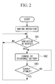
- the utility grid voltage sensor 17 measures the voltage of the utility grid 15 and informs the control section 18 of the measurement result.
- the control section 18 detects that the voltage of the utility grid 15 varied (step SB1).
- the variation condition is set such as, a case where the voltage is 20% higher than the reference voltage of the utility grid 15 for 150 milliseconds or more, a case where the voltage is 10% higher than the reference voltage for three seconds or more, a case where the voltage is 10% lower than the reference voltage for 40 milliseconds or more, or the like.
- control section 18 In a case where the control section 18 detects that the voltage of the utility grid 15 satisfies the variation condition, the control section 18 controls the connection switching section 14 to disconnect the generator 13 from the utility grid 15 and to connect the generator 13 with the load 20. In this way, sudden increase in the rotation speed of the wind turbine rotor 11 immediately after the generator 13 is disconnected from the utility grid 15 is suppressed and overspeed of the wind turbine rotor 11 can be prevented (step SB2).
- the output of the generator 13 gradually decreases.
- the control section 18 switches connection of the connection switching section 14 and grounds the generator 13 via the connection switching section 14 (step SB3).
- the utility grid voltage sensor 17 measures the voltage of the utility grid 15 on the utility grid 15 side and the measurement value is outputted to the electric power regulation control section 213.
- the electric power regulation control section 213 determines the reactive current corresponding to the voltage detected by the utility grid voltage sensor 17 based on a table kept by the section 213.
- the electric power regulation control section 213 causes the electric storage device 211 to discharge the electric power and causes the electric power converter 212 to carry out the AC-DC conversion of the discharged DC power and output the converted power to the utility grid 15 so as to supply the determined reactive current to the utility grid 15 (step SB2).
- control section 18 controls the connection switching section 14 to connect the generator 13 with the utility grid 15 so as to interconnect the generator 13 (step SB5).
- the generator 13 is disconnected from the utility grid 15 and the reactive power is regulated by the special device (the reactive power regulating section 2) for regulating the reactive power. Therefore, it is possible to supply or absorb the stable reactive power to or from the utility grid 15.
- the connection switching section 14 disconnects the generator 13 from the utility grid 15 and connects the generator 13 with the load 20, and the special device (the reactive power regulating section 21) for supplying the reactive power is connected to the utility grid 15.
- the reactive power regulating section 21 by connecting the reactive power regulating section 21 in the case where the voltage of the utility grid 15 satisfies the variation condition and the generator 13 is disconnected from the utility grid 15, it is possible to supply or absorb the stable reactive power to or from the utility grid 15. In this way, it is possible to stabilize the reactive power upon the utility grid failure while utilizing the existing wind power generating apparatus employing the squirrel-cage induction generator.
- the generator 13 and the load 20 are connected with each other to cause the discharging resistor to output the output of the generator 13 and consume electric power.
- the generator 13 and the load 20 e.g., the discharging resistor
- the utility grid stabilization apparatus 2 includes the load 20, the electric storage device 211, the electric power converter 212, and the like, it is possible to easily install the stabilization apparatus in the existing wind power generating system provided with the squirrel-cage induction generator.
Landscapes
- Engineering & Computer Science (AREA)
- Power Engineering (AREA)
- Control Of Eletrric Generators (AREA)
- Supply And Distribution Of Alternating Current (AREA)
Applications Claiming Priority (1)
| Application Number | Priority Date | Filing Date | Title |
|---|---|---|---|
| PCT/JP2009/060321 WO2010140247A1 (ja) | 2009-06-05 | 2009-06-05 | 系統安定化装置、方法、及び風力発電システム |
Publications (1)
| Publication Number | Publication Date |
|---|---|
| EP2439830A1 true EP2439830A1 (de) | 2012-04-11 |
Family
ID=43297393
Family Applications (1)
| Application Number | Title | Priority Date | Filing Date |
|---|---|---|---|
| EP09740620A Withdrawn EP2439830A1 (de) | 2009-06-05 | 2009-06-05 | Stabilisationsvorrichtung für ein system, verfahren und windkraftanlage |
Country Status (8)
| Country | Link |
|---|---|
| US (1) | US20110320052A1 (de) |
| EP (1) | EP2439830A1 (de) |
| JP (1) | JP5260555B2 (de) |
| KR (1) | KR101148298B1 (de) |
| CN (1) | CN101981779B (de) |
| BR (1) | BRPI0909243A2 (de) |
| CA (1) | CA2717125A1 (de) |
| WO (1) | WO2010140247A1 (de) |
Cited By (2)
| Publication number | Priority date | Publication date | Assignee | Title |
|---|---|---|---|---|
| EP4044388A1 (de) * | 2021-02-15 | 2022-08-17 | Siemens Gamesa Renewable Energy A/S | Windturbinenpark und verfahren zum betrieb |
| WO2022171890A1 (en) * | 2021-02-15 | 2022-08-18 | Siemens Gamesa Renewable Energy A/S | Wind turbine farm and method for operating |
Families Citing this family (15)
| Publication number | Priority date | Publication date | Assignee | Title |
|---|---|---|---|---|
| GB0816637D0 (en) * | 2008-09-12 | 2008-10-22 | Rolls Royce Plc | Blade Pitch Control |
| GB0816636D0 (en) * | 2008-09-12 | 2008-10-22 | Rolls Royce Plc | Controlling rotor overspeed |
| US20120056425A1 (en) * | 2010-09-02 | 2012-03-08 | Clipper Windpower, Inc. | Stand alone operation system for use with utility grade synchronous wind turbine generators |
| BRPI1100017A2 (pt) * | 2011-03-04 | 2016-05-03 | Mitsubishi Heavy Ind Ltd | sistema de gerador de turbina eolica, e, gerador de turbina eolica |
| ES2710311T3 (es) * | 2012-11-20 | 2019-04-24 | Vestas Wind Sys As | Métodos y sistemas para reducir el impacto de un cortocircuito de generador en una turbina eólica |
| CN104969436B (zh) * | 2013-02-07 | 2018-05-22 | 维斯塔斯风力系统集团公司 | 用于提供电网辅助服务的发电厂和能量存储系统 |
| PL2971758T3 (pl) * | 2013-03-11 | 2019-03-29 | Illing Engineering Services | System sterowania turbiną wiatrową |
| DE102013206119A1 (de) * | 2013-04-08 | 2014-10-09 | Wobben Properties Gmbh | Windenergieanlage und Verfahren zum Betreiben einer Windenergieanlage |
| EP2868919A1 (de) * | 2013-11-05 | 2015-05-06 | Openhydro IP Limited | Turbulenzenschutzsystem und -verfahren für Windturbinengeneratoren |
| KR20160059551A (ko) * | 2014-11-18 | 2016-05-27 | (주)인텍에프에이 | 슈퍼 커패시터를 이용한 전력 품질 보상 장치 및 그 동작 방법 |
| CN105162161B (zh) * | 2015-08-25 | 2017-07-07 | 国家电网公司 | 一种含有不同类型风机的外送风电基地暂态切机控制方法 |
| DE102015114704A1 (de) * | 2015-09-03 | 2017-03-09 | Wobben Properties Gmbh | Verfahren zum Einspeisen elektrischer Leistung |
| KR101589418B1 (ko) * | 2015-11-20 | 2016-01-28 | 서창전기통신 주식회사 | 풍력발전시스템의 출력 안정화 장치 |
| US10714937B2 (en) * | 2016-03-04 | 2020-07-14 | Kabushiki Kaisha Toshiba | Voltage reactive power control device and voltage reactive power control method |
| JP7086820B2 (ja) * | 2018-11-07 | 2022-06-20 | 三菱重工業株式会社 | 無効電力制御装置及び無効電力制御方法 |
Family Cites Families (16)
| Publication number | Priority date | Publication date | Assignee | Title |
|---|---|---|---|---|
| US5083039B1 (en) * | 1991-02-01 | 1999-11-16 | Zond Energy Systems Inc | Variable speed wind turbine |
| US6487096B1 (en) * | 1997-09-08 | 2002-11-26 | Capstone Turbine Corporation | Power controller |
| US6300689B1 (en) * | 1998-05-04 | 2001-10-09 | Ocean Power Technologies, Inc | Electric power generating system |
| JP3352662B2 (ja) * | 2000-02-03 | 2002-12-03 | 関西電力株式会社 | 二次電池システムを用いた電力系統安定化装置および電力系統安定化方法 |
| JP3607561B2 (ja) * | 2000-03-22 | 2005-01-05 | 日本碍子株式会社 | 無効電力補償装置の力率一定制御方法 |
| ATE490591T1 (de) * | 2002-09-10 | 2010-12-15 | Dewind Co | Betriebsverfahren für windenergieanlage mit übersynchroner kaskade |
| JP2004320859A (ja) * | 2003-04-14 | 2004-11-11 | Hitachi Ltd | 無効電力補償装置 |
| JP2006148989A (ja) * | 2004-11-16 | 2006-06-08 | Mitsubishi Electric Corp | 風力発電システム |
| JP2006246661A (ja) * | 2005-03-04 | 2006-09-14 | Neic-Japan Corp | 風力発電装置 |
| WO2007003183A1 (en) * | 2005-07-01 | 2007-01-11 | Vestas Wind Systems A/S | A variable rotor speed wind turbine, wind park, method of transmitting electric power and method of servicing or inspecting a variable rotor speed wind turbine |
| US7312537B1 (en) * | 2006-06-19 | 2007-12-25 | General Electric Company | Methods and apparatus for supplying and/or absorbing reactive power |
| EP1914872A1 (de) * | 2006-10-17 | 2008-04-23 | Siemens Aktiengesellschaft | Windpark |
| JP4501958B2 (ja) * | 2007-05-09 | 2010-07-14 | 株式会社日立製作所 | 風力発電システムおよびその制御方法 |
| CA2715238A1 (en) * | 2008-02-15 | 2009-08-20 | Wind To Power System, S.L. | Series voltage compensator and method for series voltage compensation in electrical generators |
| US20110057446A1 (en) * | 2008-03-28 | 2011-03-10 | Jesus Mayor Lusarreta | Wind turbine operation method and system |
| US8120932B2 (en) * | 2008-07-01 | 2012-02-21 | American Superconductor Corporation | Low voltage ride through |
-
2009
- 2009-06-05 CA CA2717125A patent/CA2717125A1/en not_active Abandoned
- 2009-06-05 BR BRPI0909243-9A patent/BRPI0909243A2/pt not_active IP Right Cessation
- 2009-06-05 JP JP2009546540A patent/JP5260555B2/ja not_active Expired - Fee Related
- 2009-06-05 CN CN2009801108542A patent/CN101981779B/zh not_active Expired - Fee Related
- 2009-06-05 KR KR1020107021038A patent/KR101148298B1/ko not_active IP Right Cessation
- 2009-06-05 US US12/451,330 patent/US20110320052A1/en not_active Abandoned
- 2009-06-05 WO PCT/JP2009/060321 patent/WO2010140247A1/ja active Application Filing
- 2009-06-05 EP EP09740620A patent/EP2439830A1/de not_active Withdrawn
Non-Patent Citations (1)
| Title |
|---|
| See references of WO2010140247A1 * |
Cited By (2)
| Publication number | Priority date | Publication date | Assignee | Title |
|---|---|---|---|---|
| EP4044388A1 (de) * | 2021-02-15 | 2022-08-17 | Siemens Gamesa Renewable Energy A/S | Windturbinenpark und verfahren zum betrieb |
| WO2022171890A1 (en) * | 2021-02-15 | 2022-08-18 | Siemens Gamesa Renewable Energy A/S | Wind turbine farm and method for operating |
Also Published As
| Publication number | Publication date |
|---|---|
| JPWO2010140247A1 (ja) | 2012-11-15 |
| CN101981779B (zh) | 2013-09-04 |
| KR20110016858A (ko) | 2011-02-18 |
| JP5260555B2 (ja) | 2013-08-14 |
| US20110320052A1 (en) | 2011-12-29 |
| WO2010140247A1 (ja) | 2010-12-09 |
| BRPI0909243A2 (pt) | 2015-08-25 |
| CA2717125A1 (en) | 2010-12-05 |
| KR101148298B1 (ko) | 2012-05-21 |
| CN101981779A (zh) | 2011-02-23 |
Similar Documents
| Publication | Publication Date | Title |
|---|---|---|
| EP2439830A1 (de) | Stabilisationsvorrichtung für ein system, verfahren und windkraftanlage | |
| JP5308511B2 (ja) | 風力発電設備の出力制御方法及び出力制御装置 | |
| EP2306001B1 (de) | Mehrzweckenergiespeicher für erneuerbare Quellen | |
| EP2101392B1 (de) | Speicherungs- und Frequenzsteuerung von Windturbinenenergie | |
| EP1651865B2 (de) | Verfahren zur steuerung einer windturbine während einer fehlfunktion im elektrisches netz, steuerungssystem, windkraftanlage und dessen familie | |
| CN108604795B (zh) | 风力涡轮机故障穿越能力 | |
| EP2798718B1 (de) | Windenergieanlage | |
| US20120087792A1 (en) | Emergency feather rate limit with proportionality to operating pitch angle and energy storage voltage | |
| WO2007132303A1 (en) | Wind turbine system with ac servo motor rotor blade pitch control, using super-capacitor energy storage | |
| US9551323B2 (en) | Power plant control during a low voltage or a high voltage event | |
| WO2015078471A1 (en) | Reconfiguration of the reactive power loop of a wind power plant | |
| KR20120135002A (ko) | 풍력 발전 시스템 및 풍력 발전 장치 | |
| US20120056425A1 (en) | Stand alone operation system for use with utility grade synchronous wind turbine generators | |
| CN112368901A (zh) | 带有电池存储系统的可再生能源发电厂的增强型多电压骤降穿越 | |
| EP2824323A1 (de) | Betreiben von Windturbinen als Dämpflasten | |
| AU2009342168A1 (en) | Utility grid stabilization apparatus and method, as well as wind power generating system | |
| WO2010109262A2 (en) | A redundant, supercapacitor, back-up power supply for wind turbine conversion and control systems | |
| WO2016033769A1 (en) | Method and system for coordinating control of wind farm during disconnection to utility grid | |
| TWI393320B (zh) | System stabilization devices, methods, and wind power generation systems | |
| EP4007110A1 (de) | Betrieb einer windturbine in einem netzunabhängigen autonomen modus | |
| Ullah et al. | The use of a combined battery/super capacitor storage to provide voltage ride-through capability and transient stabilizing properties by wind turbines |
Legal Events
| Date | Code | Title | Description |
|---|---|---|---|
| PUAI | Public reference made under article 153(3) epc to a published international application that has entered the european phase |
Free format text: ORIGINAL CODE: 0009012 |
|
| 17P | Request for examination filed |
Effective date: 20091105 |
|
| AK | Designated contracting states |
Kind code of ref document: A1 Designated state(s): AT BE BG CH CY CZ DE DK EE ES FI FR GB GR HR HU IE IS IT LI LT LU LV MC MK MT NL NO PL PT RO SE SI SK TR |
|
| DAX | Request for extension of the european patent (deleted) | ||
| STAA | Information on the status of an ep patent application or granted ep patent |
Free format text: STATUS: THE APPLICATION HAS BEEN WITHDRAWN |
|
| 18W | Application withdrawn |
Effective date: 20130620 |