EP2439366A2 - Device for opening sliding doors for cold rooms - Google Patents
Device for opening sliding doors for cold rooms Download PDFInfo
- Publication number
- EP2439366A2 EP2439366A2 EP20110183358 EP11183358A EP2439366A2 EP 2439366 A2 EP2439366 A2 EP 2439366A2 EP 20110183358 EP20110183358 EP 20110183358 EP 11183358 A EP11183358 A EP 11183358A EP 2439366 A2 EP2439366 A2 EP 2439366A2
- Authority
- EP
- European Patent Office
- Prior art keywords
- bush
- central shaft
- door
- door panel
- guides
- Prior art date
- Legal status (The legal status is an assumption and is not a legal conclusion. Google has not performed a legal analysis and makes no representation as to the accuracy of the status listed.)
- Granted
Links
- 230000008878 coupling Effects 0.000 claims description 2
- 238000010168 coupling process Methods 0.000 claims description 2
- 238000005859 coupling reaction Methods 0.000 claims description 2
- 230000006835 compression Effects 0.000 description 1
- 238000007906 compression Methods 0.000 description 1
- 230000002452 interceptive effect Effects 0.000 description 1
Images


Classifications
-
- E—FIXED CONSTRUCTIONS
- E05—LOCKS; KEYS; WINDOW OR DOOR FITTINGS; SAFES
- E05F—DEVICES FOR MOVING WINGS INTO OPEN OR CLOSED POSITION; CHECKS FOR WINGS; WING FITTINGS NOT OTHERWISE PROVIDED FOR, CONCERNED WITH THE FUNCTIONING OF THE WING
- E05F11/00—Man-operated mechanisms for operating wings, including those which also operate the fastening
- E05F11/54—Man-operated mechanisms for operating wings, including those which also operate the fastening for doors
-
- E—FIXED CONSTRUCTIONS
- E05—LOCKS; KEYS; WINDOW OR DOOR FITTINGS; SAFES
- E05B—LOCKS; ACCESSORIES THEREFOR; HANDCUFFS
- E05B1/00—Knobs or handles for wings; Knobs, handles, or press buttons for locks or latches on wings
- E05B1/003—Handles pivoted about an axis perpendicular to the wing
-
- E—FIXED CONSTRUCTIONS
- E05—LOCKS; KEYS; WINDOW OR DOOR FITTINGS; SAFES
- E05B—LOCKS; ACCESSORIES THEREFOR; HANDCUFFS
- E05B17/00—Accessories in connection with locks
- E05B17/0025—Devices for forcing the wing firmly against its seat or to initiate the opening of the wing
- E05B17/0033—Devices for forcing the wing firmly against its seat or to initiate the opening of the wing for opening only
-
- F—MECHANICAL ENGINEERING; LIGHTING; HEATING; WEAPONS; BLASTING
- F25—REFRIGERATION OR COOLING; COMBINED HEATING AND REFRIGERATION SYSTEMS; HEAT PUMP SYSTEMS; MANUFACTURE OR STORAGE OF ICE; LIQUEFACTION SOLIDIFICATION OF GASES
- F25D—REFRIGERATORS; COLD ROOMS; ICE-BOXES; COOLING OR FREEZING APPARATUS NOT OTHERWISE PROVIDED FOR
- F25D23/00—General constructional features
- F25D23/02—Doors; Covers
- F25D23/021—Sliding doors
-
- E—FIXED CONSTRUCTIONS
- E05—LOCKS; KEYS; WINDOW OR DOOR FITTINGS; SAFES
- E05B—LOCKS; ACCESSORIES THEREFOR; HANDCUFFS
- E05B63/00—Locks or fastenings with special structural characteristics
- E05B63/0056—Locks with adjustable or exchangeable lock parts
- E05B63/006—Locks with adjustable or exchangeable lock parts for different door thicknesses
-
- E—FIXED CONSTRUCTIONS
- E05—LOCKS; KEYS; WINDOW OR DOOR FITTINGS; SAFES
- E05B—LOCKS; ACCESSORIES THEREFOR; HANDCUFFS
- E05B63/00—Locks or fastenings with special structural characteristics
- E05B63/04—Locks or fastenings with special structural characteristics for alternative use on the right-hand or left-hand side of wings
- E05B63/042—Locks or fastenings with special structural characteristics for alternative use on the right-hand or left-hand side of wings constructed symmetrically
-
- E—FIXED CONSTRUCTIONS
- E05—LOCKS; KEYS; WINDOW OR DOOR FITTINGS; SAFES
- E05B—LOCKS; ACCESSORIES THEREFOR; HANDCUFFS
- E05B65/00—Locks or fastenings for special use
- E05B65/0042—For refrigerators or cold rooms
- E05B65/0053—For refrigerators or cold rooms with safety release from inside
-
- E—FIXED CONSTRUCTIONS
- E05—LOCKS; KEYS; WINDOW OR DOOR FITTINGS; SAFES
- E05Y—INDEXING SCHEME RELATING TO HINGES OR OTHER SUSPENSION DEVICES FOR DOORS, WINDOWS OR WINGS AND DEVICES FOR MOVING WINGS INTO OPEN OR CLOSED POSITION, CHECKS FOR WINGS AND WING FITTINGS NOT OTHERWISE PROVIDED FOR, CONCERNED WITH THE FUNCTIONING OF THE WING
- E05Y2900/00—Application of doors, windows, wings or fittings thereof
- E05Y2900/10—Application of doors, windows, wings or fittings thereof for buildings or parts thereof
- E05Y2900/102—Application of doors, windows, wings or fittings thereof for buildings or parts thereof for cold-rooms
Definitions
- the present invention relates to a device enabling the door panel of a cold room sliding door to be released from its closed position.
- doors of this type comprise a door panel sliding on guides disposed parallel to the wall in which the door aperture is provided. These door panel guides are shaped such that when the door panel is moved from its maximum open position (which leaves the entire aperture uncovered) to its closed position, just before it reaches this latter position the door panel is made to approach the wall and floor such that these press against the gaskets, carried by the door panel, which ensure the seal.
- These doors are provided with a device which enables the door to be easily released, and which levers against one side of the door aperture (normally against the relative upright of the frame defining the door aperture) so as to withdraw the door panel from this upright by overcoming both the opposing resistance and friction, also exerted by said seal gasket when in its compressed state.
- a known device of this type comprises:
- the aforedescribed device releases the door panel when in its closed position. Once released, the door panel can be manually moved until the door is completely open.
- the bush in the case of a door with leftward opening, the bush must have its slot inclination opposite that of a bush for rightward opening doors.
- the aforedescribed internal handle is also different (specular) in the two cases, although it can be easily produced such as to be able to be fixed to the central shaft in a determined position compatible for example with rightward opening and also in an inverted position to be also compatible with leftward opening.
- door panels for cold rooms can have different thicknesses (in particular thicknesses of 70, 80, 90, 100 and exceptionally 120 mm), so that the current manufacturers of devices of this type have to produce bushes of the corresponding length (bushes of five different lengths in the specific case of the aforesaid thicknesses), but for each bush length two bushes have to be produced having opposingly inclined slots, for rightward opening and leftward opening doors.
- a cold room sliding door manufacturer must currently stock ten different bush types.
- An object of the present invention is therefore to provide a device of the aforesaid type which is adaptable to all or at least a part of the currently required door panel thicknesses for doors of this type.
- the coupling between the ring cap and bush is of "telescopic" type, means (in particular screws) being provided to fix the ring cap to the bush such as to obtain the required length of the bush-ring cap assembly.
- Said guide means for the central shaft can in particular comprise two opposing guides provided in the inner wall of the bush, the guides having an inclination to the bush axis which is compatible with the door opening direction, these guides cooperating for this purpose with respective pawls projecting radially from the central shaft.
- Another object of the present invention is to provide a device of the aforesaid type which besides being adaptable to all or at least part of the commercially required door panel thicknesses is usable for both rightward opening and leftward opening sliding doors.
- first guide means for the central shaft which enable it to rotate in the direction corresponding to a door with a determined opening direction
- second guide means which enable the central shaft to rotate in the opposite direction corresponding to the opening direction of a door with opposite opening direction.
- the guide means can have a fixed limit stop corresponding to the angular position of the central shaft relative to the released door panel, the other limit stop being removable and positionable, depending on whether the door has rightward opening or leftward opening, to operate as a limit stop for rightward opening or leftward opening guide means respectively.
- the device shown therein comprises a bush 12, shown in greater detail in Figures 3-5 , and a ring cap 14 to be mounted coaxially on the bush 12 and fixed thereto by (in the specific illustrated case) three screws insertable through corresponding through holes provided in the ring cap 14, the screws 16 being insertable through relative holes 17 and screwed into threaded holes 18 provided in the bush 12.
- an entire set of holes 18 is provided to enable, by means of a type of telescopic joint, the overall length of the bush-ring cap assembly to be adjusted to adapt it to the thickness of the specific sliding door panel to which the device 10 is to be applied.
- doors are currently available having thicknesses of 70, 80, 90, 100, 120 mm, so that the position of the holes 18 on the bush 12 in the axial direction is chosen such that the length of the bush 12-ring cap 14 assembly is compatible with said door panel thicknesses.
- doors can be formed having door panels with a larger range of thicknesses, i.e. thicknesses much closer to specific requirements (for example a series of thicknesses differing from each other by 5 mm).
- the device 10 also comprises a central shaft 20 ( Figures 1 , 2 , 8 and 9 ) inserted coaxially into the bush 12-ring cap 14 assembly such that it can rotate about its own axis, but also translate in both directions along this axis.
- the central shaft 20 presents a diametrical through hole 22 arranged to receive a diametrical pin 24 the two ends of which project equally from the central shaft 20 to form two respective pawls (indicated for simplicity by the same reference numeral as the pin 24) which cooperate with corresponding guides (described below) formed by recesses provided in the interior of the bush 12.
- These guides consist essentially of one of the edges of a relative recess, this edge being inclined to the axis of the bush 12.
- the same bush 12 also presents at the same time a second pair of opposite guides suitable for a rightward opening door.
- the guides of this second pair are disposed rotated through 90° to those of the first pair and have opposite inclination.
- a guide of the second pair, indicated by 27, is visible in Figure 5 .
- the device 10 also comprises a helical spring 28 which when the device 10 is mounted is preloaded and rests with one end on a collar 30 of the central shaft 20 whereas its other end rests against the step 32 in the interior of the bush 12.
- the spring 28 causes the central shaft 20 to withdraw outwards until the two pawls 24 abut against the two stop elements 36 fixable to the bush 12, this latter presenting for this purpose two relative seats 38 (also see Figure 3 ).
- the arched arm of the stop elements 36 enables the movement of the relative pawl 24 along the guide 26 to be also limited from the other side.
- the device 10 can be adapted to a door with rightward opening rather than with leftward opening.
- the device 10 also comprises two covers 40 and 42 positioned on the inside of the door panel, which are used to fix the bush 12-ring cap 14 assembly to the door panel, and also an external handle 44 and an internal handle 46.
- the external handle 44 is fixed to one end of the central shaft 20 by simply inserting its near end into the dead hole 48 provided in the central shaft 20, to then lock it in position with a screw 50
- the internal handle 46 is fixed to the central shaft 20 by a form fit (not visible completely, but of conventional type) and two screws (of which for simplicity only one, indicated by 52, is shown in Figures 1 and 2 ).
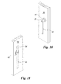
- the internal handle 46 is essentially a lever with its fulcrum corresponding to the axis of the central shaft 20, there also being present (also see Figure 11 ) a hammer head 54 arranged to abut against the relative upright (not shown) of the frame bounding the door, whether rightward opening or leftward opening. It can also be seen that the internal handle 46 has a rectangular cross-section with its minor sides parallel to the axis of the central shaft 20, in order that the thickness of this handle in the direction perpendicular to the door panel is not such as to interfere, during door opening, with the frame of this latter.
- the external handle 44 has to be rotated clockwise, this causing the door panel to move towards the left and, because of the shape of the relative guide, to withdraw such that it can be opened without the door panel seal gaskets interfering with the door frame.
- rotating the handle 44 causes the pawls 24 to move along the relative guides 26 until the pawls 24 become positioned against the limit stops 36. If the handle 44 is left free at this point, the action of the spring 28 returns the pawls 24 into the corresponding grooves 34, the handle 44 consequently returning into the vertical position (withdrawn position, so that it does not interfere with the door frame when the door is opened completely, such that the entire door aperture is usable).
- the door panel needs merely to be returned to its closed position.
Landscapes
- Engineering & Computer Science (AREA)
- Chemical & Material Sciences (AREA)
- Combustion & Propulsion (AREA)
- Physics & Mathematics (AREA)
- Mechanical Engineering (AREA)
- Thermal Sciences (AREA)
- General Engineering & Computer Science (AREA)
- Hinges (AREA)
- Closures For Containers (AREA)
- Lock And Its Accessories (AREA)
- Refrigerator Housings (AREA)
Abstract
Description
- The present invention relates to a device enabling the door panel of a cold room sliding door to be released from its closed position.
- As known to the expert of the art, doors of this type comprise a door panel sliding on guides disposed parallel to the wall in which the door aperture is provided. These door panel guides are shaped such that when the door panel is moved from its maximum open position (which leaves the entire aperture uncovered) to its closed position, just before it reaches this latter position the door panel is made to approach the wall and floor such that these press against the gaskets, carried by the door panel, which ensure the seal.
- These doors are provided with a device which enables the door to be easily released, and which levers against one side of the door aperture (normally against the relative upright of the frame defining the door aperture) so as to withdraw the door panel from this upright by overcoming both the opposing resistance and friction, also exerted by said seal gasket when in its compressed state.
- As also known to the expert of the art, a known device of this type comprises:
- a bush having a length substantially equal to the door panel thickness in order to be able to be incorporated into the door panel with its axis perpendicular thereto, the bush laterally presenting at least two opposing through slots, the axes of which must have their inclination opposite the bush axis, with the inclination of the slot axes in a door with rightward opening being opposite that of a door with leftward opening;
- a central shaft coaxially inserted into the bush such that it can be rotated about its axis and be moved along said axis, and of which the length enables it to project from both sides of the door panel;
- a number of pawls projecting radially from said central shaft equal to the number of slots provided in said bush, each pawl engaging in a relative slot;
- an external handle, consisting of a rather lengthy bar (even more than 50 cm) fixed to the outer end of the central shaft and extending radially from it (normally disposed vertically downwards when the door is closed);
- an internal handle, consisting of a lever fixed to the shaft and which, with the door closed, extends both upwards and downwards from the central shaft (which forms its fulcrum), the free end of its upper part being deviated to the left if the door is of rightward opening type and to the right if of leftward opening type, such that with the door closed, this free end rests against the vertical upright of the door frame;
- a preloaded helical spring, mounted coaxially on the central shaft such that one end rests on a relative shoulder provided inside the bush, while the other end of the spring rests on a collar provided on the central shaft, the spring maintaining the shaft-handle assembly in a position withdrawn outward from the door panel when this latter has been released, so as not to interfere with said gaskets when the door is completely opened.
- Essentially, by simply rotating the external handle anticlockwise if the sliding door opens rightwards or clockwise if it opens leftwards, and consequently causing the internal handle to rotate and act as a lever with its upper end acting against the door frame, the aforedescribed device releases the door panel when in its closed position. Once released, the door panel can be manually moved until the door is completely open.
- In contrast, after then manually sliding the door panel into its closed position, as the shaft-handle assembly (because of the action of said helical spring) is still in its rotated and withdrawn position because of having previously opened the door, the upper end of the internal handle rests against the relative upright of the door frame before the door panel arrives in its completely closed position. Completing closure of the door panel causes the internal handle to rotate (viewing from the outside) and to move inwards, against the action of the helical spring, until the shaft-handle assembly assumes the already described closed position.
- It has already been stated that in the case of a door with leftward opening, the bush must have its slot inclination opposite that of a bush for rightward opening doors. The aforedescribed internal handle is also different (specular) in the two cases, although it can be easily produced such as to be able to be fixed to the central shaft in a determined position compatible for example with rightward opening and also in an inverted position to be also compatible with leftward opening.
- It should also be noted that door panels for cold rooms can have different thicknesses (in particular thicknesses of 70, 80, 90, 100 and exceptionally 120 mm), so that the current manufacturers of devices of this type have to produce bushes of the corresponding length (bushes of five different lengths in the specific case of the aforesaid thicknesses), but for each bush length two bushes have to be produced having opposingly inclined slots, for rightward opening and leftward opening doors. Hence a cold room sliding door manufacturer must currently stock ten different bush types.
- An object of the present invention is therefore to provide a device of the aforesaid type which is adaptable to all or at least a part of the currently required door panel thicknesses for doors of this type.
- This object is attained by the device of the present invention for rightward opening or leftward opening sliding doors, comprising:
- a bush incorporated into the thickness of the door panel and fixed thereto such that its axis is perpendicular to the door panel;
- a central shaft coaxially inserted into the bush to be able both to rotate about the axis of this latter and to move along said axis;
- means for guiding the movement and rotation of the central shaft, which enable it to rotate in the direction compatible with the door opening direction;
- elastic means to bring the central shaft into a position withdrawn outwards from the door panel when left free to move coaxially;
- external means for rotating the central shaft;
- internal means for rotating the central shaft and provided with a striker adapted to come into contact with a fixed point (for example the relative side of the door frame) such that, following forced rotation, achieved by said external or internal means, of the central shaft in the direction compatible with the door opening direction, a consequent forcing of said striker against said fixed point is obtained, such as to cause release of the door,
- According to one embodiment of the present invention, the coupling between the ring cap and bush is of "telescopic" type, means (in particular screws) being provided to fix the ring cap to the bush such as to obtain the required length of the bush-ring cap assembly.
- Said guide means for the central shaft can in particular comprise two opposing guides provided in the inner wall of the bush, the guides having an inclination to the bush axis which is compatible with the door opening direction, these guides cooperating for this purpose with respective pawls projecting radially from the central shaft.
- Another object of the present invention is to provide a device of the aforesaid type which besides being adaptable to all or at least part of the commercially required door panel thicknesses is usable for both rightward opening and leftward opening sliding doors.
- This object is also attained by the device of the present invention in which, provided in one and the same bush, there are both first guide means for the central shaft which enable it to rotate in the direction corresponding to a door with a determined opening direction, and second guide means which enable the central shaft to rotate in the opposite direction corresponding to the opening direction of a door with opposite opening direction.
- This can be easily achieved for example by providing in the bush interior two first opposing guides which extend with an inclination to the bush axis which is compatible with a door having a determined opening direction, and two second opposing guide means which extend with an inclination compatible with the other opening direction, with the result that the first guides have the opposite inclination to the two second guides.
- In particular, the guide means can have a fixed limit stop corresponding to the angular position of the central shaft relative to the released door panel, the other limit stop being removable and positionable, depending on whether the door has rightward opening or leftward opening, to operate as a limit stop for rightward opening or leftward opening guide means respectively.
- The invention will be more easily understood from the following description of one embodiment thereof given by way of example. In this description reference is made to the accompanying drawings, in which:
-
Figure 1 is an exploded perspective view of a device according to the present invention; -
Figure 2 is a second exploded perspective view thereof, but from another viewpoint; -
Figure 3 is a rear view, with reference toFigure 1 , of the bush shown in that figure; -
Figure 4 is a section therethrough taken on the line 4-4 ofFigure 3 ; -
Figure 5 is a section therethrough taken on the line 5-5 ofFigure 3 ; -
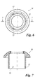
Figure 6 is a rear view, again with reference toFigure 1 , of the ring cap visible in that figure; -
Figure 7 is a section therethrough, taken on the line 7-7 ofFigure 6 ; -
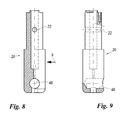
Figure 8 shows in the right part an enlarged plan view from above of the central shaft visible inFigure 1 , and in the left part a horizontal coaxial section therethrough; -
Figure 9 is a partly sectioned lateral view thereof in the direction of the arrow 9 ofFigure 8 ; -
Figure 10 is a perspective view of the external handle as it appears once applied to a cold room sliding door panel (shown partially) with leftward opening; -
Figure 11 is a perspective view of the internal handle applied to the same door panel. - As can be seen in
Figures 1 and2 , the device shown therein, indicated overall by 10, comprises abush 12, shown in greater detail inFigures 3-5 , and aring cap 14 to be mounted coaxially on thebush 12 and fixed thereto by (in the specific illustrated case) three screws insertable through corresponding through holes provided in thering cap 14, thescrews 16 being insertable throughrelative holes 17 and screwed into threadedholes 18 provided in thebush 12. As can be seen fromFigures 1 and2 , an entire set ofholes 18 is provided to enable, by means of a type of telescopic joint, the overall length of the bush-ring cap assembly to be adjusted to adapt it to the thickness of the specific sliding door panel to which thedevice 10 is to be applied. It has already been stated, by way of example, that doors are currently available having thicknesses of 70, 80, 90, 100, 120 mm, so that the position of theholes 18 on thebush 12 in the axial direction is chosen such that the length of the bush 12-ring cap 14 assembly is compatible with said door panel thicknesses. In fact, by virtue of the device of the present invention, doors can be formed having door panels with a larger range of thicknesses, i.e. thicknesses much closer to specific requirements (for example a series of thicknesses differing from each other by 5 mm). - The
device 10 also comprises a central shaft 20 (Figures 1 ,2 ,8 and 9 ) inserted coaxially into the bush 12-ring cap 14 assembly such that it can rotate about its own axis, but also translate in both directions along this axis. As best seen inFigures 8 and 9 , thecentral shaft 20 presents a diametrical throughhole 22 arranged to receive adiametrical pin 24 the two ends of which project equally from thecentral shaft 20 to form two respective pawls (indicated for simplicity by the same reference numeral as the pin 24) which cooperate with corresponding guides (described below) formed by recesses provided in the interior of thebush 12. These guides consist essentially of one of the edges of a relative recess, this edge being inclined to the axis of thebush 12. One of the two guides, indicated by 26, is visible inFigure 4 . Therelative pawl 24 rests against this guide. It should be noted that theguide 26 is suitable for a sliding door with leftward opening. Theother pawl 24 is guided by a similar edge of a corresponding recess (not visible in the figures because it is opposite that of theguide 26, it being inverted to be able to perform the same function when thecentral shaft 20 is rotated in the anticlockwise direction with reference toFigure 1 ). - It should be noted that the
same bush 12 also presents at the same time a second pair of opposite guides suitable for a rightward opening door. The guides of this second pair are disposed rotated through 90° to those of the first pair and have opposite inclination. A guide of the second pair, indicated by 27, is visible inFigure 5 . - The
device 10 also comprises ahelical spring 28 which when thedevice 10 is mounted is preloaded and rests with one end on acollar 30 of thecentral shaft 20 whereas its other end rests against thestep 32 in the interior of thebush 12. - Once a door, for example with leftward opening, has been released, the
spring 28 causes thecentral shaft 20 to withdraw outwards until the twopawls 24 abut against the twostop elements 36 fixable to thebush 12, this latter presenting for this purpose two relative seats 38 (also seeFigure 3 ). The arched arm of thestop elements 36 enables the movement of therelative pawl 24 along theguide 26 to be also limited from the other side. It should be noted that by simply inverting thestop elements 36, these no longer interfere with thepawls 24 of the first pair, but instead interfere with the saidpawls 24 when cooperating with the second pair of guides (those for a leftward opening door) Consequently, by simply orientating thebush 12 angularly in a suitable manner and fixing thestop elements 36 to thebush 12 in accordance with that of their two possible positions which corresponds to this orientation, thedevice 10 can be adapted to a door with rightward opening rather than with leftward opening. - From
Figures 1 and2 it can be seen that thedevice 10 also comprises twocovers ring cap 14 assembly to the door panel, and also anexternal handle 44 and aninternal handle 46. Theexternal handle 44 is fixed to one end of thecentral shaft 20 by simply inserting its near end into thedead hole 48 provided in thecentral shaft 20, to then lock it in position with ascrew 50, whereas theinternal handle 46 is fixed to thecentral shaft 20 by a form fit (not visible completely, but of conventional type) and two screws (of which for simplicity only one, indicated by 52, is shown inFigures 1 and2 ). It can be seen fromFigure 1 that theinternal handle 46 is essentially a lever with its fulcrum corresponding to the axis of thecentral shaft 20, there also being present (also seeFigure 11 ) ahammer head 54 arranged to abut against the relative upright (not shown) of the frame bounding the door, whether rightward opening or leftward opening. It can also be seen that theinternal handle 46 has a rectangular cross-section with its minor sides parallel to the axis of thecentral shaft 20, in order that the thickness of this handle in the direction perpendicular to the door panel is not such as to interfere, during door opening, with the frame of this latter. - The operation of the
device 10 is also apparent to an expert of the art from the aforegoing. It will however be briefly described for greater clarity with reference to a leftward opening door, the operation of a rightward opening door being consequently evident. - When the door is closed, the
external handle 44 andinternal handle 46 lie in a vertical position with the left end of thehammer head 54 close to the right upright (not shown) of the door frame (or other suitable fixed point). In this situation thepawls 24 rest in the groove 34 (Figure 4 ) and thespring 28 is in its minimum compression condition. - To release the door from the outside the
external handle 44 has to be rotated clockwise, this causing the door panel to move towards the left and, because of the shape of the relative guide, to withdraw such that it can be opened without the door panel seal gaskets interfering with the door frame. By virtue of theguides 26, rotating thehandle 44 causes thepawls 24 to move along the relative guides 26 until thepawls 24 become positioned against the limit stops 36. If thehandle 44 is left free at this point, the action of thespring 28 returns thepawls 24 into thecorresponding grooves 34, thehandle 44 consequently returning into the vertical position (withdrawn position, so that it does not interfere with the door frame when the door is opened completely, such that the entire door aperture is usable). - To close the door, the door panel needs merely to be returned to its closed position.
- In conclusion, by virtue of the device of the present invention, only one set of pieces needs to be stocked for the
device 10, and in particular only onebush 12 for an entire series of door panel thickness for the cold room sliding door, whether the door is rightward opening or leftward opening.
Claims (8)
- A device (10) for releasing a door panel (56) of a cold room sliding door from its closed position, comprising:- a bush (12) incorporated into the thickness of the door panel (56) and fixed to the door panel (56) such that its axis is perpendicular to this latter (56);- a central shaft (20) coaxially inserted into the bush (12) to be able both to rotate about the axis of this latter (12) and to move along said axis;- means (26, 24; 27, 24) for guiding the movement and rotation of the central shaft (20), which enable it to rotate in the direction compatible with the door opening direction;- elastic means (28) to bring the central shaft (20) into a position withdrawn outwards from the door panel (56) when left free to move coaxially;- external means (44) for rotating the central shaft (20);- internal means (46) for rotating the central shaft (20) and provided with a striker (54) adapted to come into contact with a fixed point such that, following forced rotation, achieved by said external means (44) or internal means (46), of the central shaft (20) in the direction compatible with the door opening direction, a consequent forcing of said striker (54) against said fixed point is obtained, such as to cause release of the door; characterised in that the bush (12) has a length less than the thickness of all or at least part of the door panels (56) of such doors, a ring cap (14) being provided coupleable coaxially to the bush (12) such that the bush (12)-ring cap (14) assembly has a length adapted to the thickness of the specific door panel (56).
- A device as claimed in claim 1, wherein the coupling between the ring cap (14) and bush (12) is of "telescopic" type, means (16) being provided to fix the ring cap (14) to the bush (12) such as to obtain the required length of the bush (12)-ring cap (14) assembly.
- A device as claimed in claim 1, wherein the guide means for the central shaft (20) comprise two opposing guides (26; 27) provided in the inner wall of the bush (12), and respective pawls (24) projecting radially from the central shaft (20) and cooperating with the guides (26; 27), these latter (26; 27) having an inclination to the bush (12) axis which is compatible with the door opening direction.
- A device as claimed in claim 1, wherein provided in one and the same bush (12) there are both first guide means (26, 24) for the central shaft (20) which enable it to rotate in the direction corresponding to a door with a determined opening direction, and second guide means (27, 24) which enable the central shaft (20) to rotate in the opposite direction, corresponding to the opening direction of a door with opposite opening direction.
- A device as claimed in claim 4, wherein the first and second guide means for the central shaft (20) comprise respectively two first guides (26) and two second guides (27) provided in the inner wall of the bush (12), the angular position of the second two guides (27) being rotated through 90° to those of the first two guides (26).
- A device as claimed in claim 3 or 5, wherein the guides (26; 27) have a fixed limit stop (34; 35) corresponding to the angular position of the central shaft (20) relative to the blocked door panel (56), the other limit stop (36) being removable and positionable, according to whether the door has rightward opening or leftward opening, to operate as a limit stop for rightward opening guide means (27, 24) or leftward opening guide means (26, 24) respectively.
- A device as claimed in claim 1, wherein the external means and the internal means for rotating the central shaft (20) comprise respective manually operable levers (44, 46).
- A device as claimed in claim 7, wherein the internal lever (46) is pivoted at an intermediate point thereof and fixed at that point to the central shaft (20), that end of the internal lever (46) opposite the gripping end presenting a striker (54) of hammer head shape intended to come into contact with the fixed striker point, on one side or the other, depending on the door opening direction.
Applications Claiming Priority (1)
| Application Number | Priority Date | Filing Date | Title |
|---|---|---|---|
| ITMI2010A001850A IT1402016B1 (en) | 2010-10-11 | 2010-10-11 | DEVICE FOR OPENING SLIDING DOORS FOR REFRIGERATED CELLS. |
Publications (3)
| Publication Number | Publication Date |
|---|---|
| EP2439366A2 true EP2439366A2 (en) | 2012-04-11 |
| EP2439366A3 EP2439366A3 (en) | 2012-07-18 |
| EP2439366B1 EP2439366B1 (en) | 2015-12-30 |
Family
ID=43737982
Family Applications (1)
| Application Number | Title | Priority Date | Filing Date |
|---|---|---|---|
| EP11183358.8A Active EP2439366B1 (en) | 2010-10-11 | 2011-09-29 | Device for opening sliding doors for cold rooms |
Country Status (2)
| Country | Link |
|---|---|
| EP (1) | EP2439366B1 (en) |
| IT (1) | IT1402016B1 (en) |
Cited By (2)
| Publication number | Priority date | Publication date | Assignee | Title |
|---|---|---|---|---|
| IT201800010701A1 (en) | 2018-11-29 | 2020-05-29 | M T H S R L | Device for opening thermal insulating sliding doors. |
| WO2020123643A1 (en) * | 2018-12-12 | 2020-06-18 | ASSA ABLOY Accessories and Door Controls Group, Inc. | Door open assist |
Family Cites Families (1)
| Publication number | Priority date | Publication date | Assignee | Title |
|---|---|---|---|---|
| DE2758521C2 (en) * | 1977-12-28 | 1984-09-20 | Markus Hermetische Deuren B.V., Krimpen aan den Ijssel | Espagnolette lock and push-off device on a horizontally sliding door |
-
2010
- 2010-10-11 IT ITMI2010A001850A patent/IT1402016B1/en active
-
2011
- 2011-09-29 EP EP11183358.8A patent/EP2439366B1/en active Active
Non-Patent Citations (1)
| Title |
|---|
| None |
Cited By (5)
| Publication number | Priority date | Publication date | Assignee | Title |
|---|---|---|---|---|
| IT201800010701A1 (en) | 2018-11-29 | 2020-05-29 | M T H S R L | Device for opening thermal insulating sliding doors. |
| EP3660246A1 (en) | 2018-11-29 | 2020-06-03 | M.T.H. S.r.l. | Device for opening thermally insulating sliding doors |
| WO2020123643A1 (en) * | 2018-12-12 | 2020-06-18 | ASSA ABLOY Accessories and Door Controls Group, Inc. | Door open assist |
| US11421443B2 (en) | 2018-12-12 | 2022-08-23 | ASSA ABLOY Accessories and Door Controls Group, Inc. | Door open assist |
| US20220349210A1 (en) * | 2018-12-12 | 2022-11-03 | ASSA ABLOY Accessories and Door Controls Group, Inc. | Door open assist |
Also Published As
| Publication number | Publication date |
|---|---|
| EP2439366B1 (en) | 2015-12-30 |
| ITMI20101850A1 (en) | 2012-04-12 |
| IT1402016B1 (en) | 2013-08-28 |
| EP2439366A3 (en) | 2012-07-18 |
Similar Documents
| Publication | Publication Date | Title |
|---|---|---|
| JP6276200B2 (en) | Lever activated compression latch | |
| US7107649B2 (en) | Hinge device | |
| US9273495B2 (en) | Panic exit door lock with an indication of a locking state | |
| KR100759713B1 (en) | Automatic close device and system of fire door | |
| US9074397B2 (en) | Adjustable door jamb locks | |
| EP3214242B1 (en) | Vehicle door latching device | |
| RU2426848C2 (en) | Device for windows or doors | |
| KR101271518B1 (en) | Pull type door lock device | |
| EP2439366B1 (en) | Device for opening sliding doors for cold rooms | |
| TWI675979B (en) | Valves and integrated valves with locking mechanism | |
| KR101842834B1 (en) | Folding door lock latching device | |
| BR112016006271B1 (en) | fan device | |
| RU2643125C2 (en) | Door lock | |
| JP6113765B2 (en) | Padlock | |
| JP7022652B2 (en) | Slide latch lock | |
| EP2657439B1 (en) | Locking device | |
| JP6501667B2 (en) | Slide latch device | |
| JP6367141B2 (en) | Door locking device | |
| DE10211704C1 (en) | Lock for a refrigerating chamber comprises an outer handle which in the open position is fixed in a force-locking manner on a lock part on the door frame by an additional closing element containing a spring-loaded latch | |
| JP6251140B2 (en) | Locking device | |
| US20050035606A1 (en) | Handle for opening and closing shoji | |
| KR200454646Y1 (en) | Tempered Glass Door Lock | |
| JP6315654B2 (en) | Shoji | |
| KR20200142334A (en) | Locking device for sliding door | |
| KR20170058646A (en) | roller fixing device of sliding door |
Legal Events
| Date | Code | Title | Description |
|---|---|---|---|
| AK | Designated contracting states |
Kind code of ref document: A2 Designated state(s): AL AT BE BG CH CY CZ DE DK EE ES FI FR GB GR HR HU IE IS IT LI LT LU LV MC MK MT NL NO PL PT RO RS SE SI SK SM TR |
|
| AX | Request for extension of the european patent |
Extension state: BA ME |
|
| PUAI | Public reference made under article 153(3) epc to a published international application that has entered the european phase |
Free format text: ORIGINAL CODE: 0009012 |
|
| PUAL | Search report despatched |
Free format text: ORIGINAL CODE: 0009013 |
|
| AK | Designated contracting states |
Kind code of ref document: A3 Designated state(s): AL AT BE BG CH CY CZ DE DK EE ES FI FR GB GR HR HU IE IS IT LI LT LU LV MC MK MT NL NO PL PT RO RS SE SI SK SM TR |
|
| AX | Request for extension of the european patent |
Extension state: BA ME |
|
| RIC1 | Information provided on ipc code assigned before grant |
Ipc: E05B 17/00 20060101ALI20120612BHEP Ipc: E05F 11/54 20060101AFI20120612BHEP Ipc: F25D 23/02 20060101ALI20120612BHEP |
|
| 17P | Request for examination filed |
Effective date: 20130108 |
|
| RIC1 | Information provided on ipc code assigned before grant |
Ipc: F25D 23/02 20060101ALI20150206BHEP Ipc: E05B 17/00 20060101ALI20150206BHEP Ipc: E05B 1/00 20060101ALI20150206BHEP Ipc: E05B 63/04 20060101ALI20150206BHEP Ipc: E05F 11/54 20060101AFI20150206BHEP Ipc: E05B 65/00 20060101ALI20150206BHEP |
|
| GRAP | Despatch of communication of intention to grant a patent |
Free format text: ORIGINAL CODE: EPIDOSNIGR1 |
|
| INTG | Intention to grant announced |
Effective date: 20150325 |
|
| GRAS | Grant fee paid |
Free format text: ORIGINAL CODE: EPIDOSNIGR3 |
|
| GRAP | Despatch of communication of intention to grant a patent |
Free format text: ORIGINAL CODE: EPIDOSNIGR1 |
|
| INTG | Intention to grant announced |
Effective date: 20150928 |
|
| GRAA | (expected) grant |
Free format text: ORIGINAL CODE: 0009210 |
|
| AK | Designated contracting states |
Kind code of ref document: B1 Designated state(s): AL AT BE BG CH CY CZ DE DK EE ES FI FR GB GR HR HU IE IS IT LI LT LU LV MC MK MT NL NO PL PT RO RS SE SI SK SM TR |
|
| AX | Request for extension of the european patent |
Extension state: BA ME |
|
| REG | Reference to a national code |
Ref country code: GB Ref legal event code: FG4D |
|
| REG | Reference to a national code |
Ref country code: CH Ref legal event code: EP |
|
| REG | Reference to a national code |
Ref country code: AT Ref legal event code: REF Ref document number: 767580 Country of ref document: AT Kind code of ref document: T Effective date: 20160115 |
|
| REG | Reference to a national code |
Ref country code: IE Ref legal event code: FG4D |
|
| REG | Reference to a national code |
Ref country code: DE Ref legal event code: R096 Ref document number: 602011022210 Country of ref document: DE |
|
| REG | Reference to a national code |
Ref country code: LT Ref legal event code: MG4D |
|
| PG25 | Lapsed in a contracting state [announced via postgrant information from national office to epo] |
Ref country code: LT Free format text: LAPSE BECAUSE OF FAILURE TO SUBMIT A TRANSLATION OF THE DESCRIPTION OR TO PAY THE FEE WITHIN THE PRESCRIBED TIME-LIMIT Effective date: 20151230 Ref country code: HR Free format text: LAPSE BECAUSE OF FAILURE TO SUBMIT A TRANSLATION OF THE DESCRIPTION OR TO PAY THE FEE WITHIN THE PRESCRIBED TIME-LIMIT Effective date: 20151230 Ref country code: NO Free format text: LAPSE BECAUSE OF FAILURE TO SUBMIT A TRANSLATION OF THE DESCRIPTION OR TO PAY THE FEE WITHIN THE PRESCRIBED TIME-LIMIT Effective date: 20160330 |
|
| REG | Reference to a national code |
Ref country code: NL Ref legal event code: MP Effective date: 20151230 |
|
| REG | Reference to a national code |
Ref country code: AT Ref legal event code: MK05 Ref document number: 767580 Country of ref document: AT Kind code of ref document: T Effective date: 20151230 |
|
| PG25 | Lapsed in a contracting state [announced via postgrant information from national office to epo] |
Ref country code: RS Free format text: LAPSE BECAUSE OF FAILURE TO SUBMIT A TRANSLATION OF THE DESCRIPTION OR TO PAY THE FEE WITHIN THE PRESCRIBED TIME-LIMIT Effective date: 20151230 Ref country code: FI Free format text: LAPSE BECAUSE OF FAILURE TO SUBMIT A TRANSLATION OF THE DESCRIPTION OR TO PAY THE FEE WITHIN THE PRESCRIBED TIME-LIMIT Effective date: 20151230 Ref country code: SE Free format text: LAPSE BECAUSE OF FAILURE TO SUBMIT A TRANSLATION OF THE DESCRIPTION OR TO PAY THE FEE WITHIN THE PRESCRIBED TIME-LIMIT Effective date: 20151230 Ref country code: LV Free format text: LAPSE BECAUSE OF FAILURE TO SUBMIT A TRANSLATION OF THE DESCRIPTION OR TO PAY THE FEE WITHIN THE PRESCRIBED TIME-LIMIT Effective date: 20151230 Ref country code: GR Free format text: LAPSE BECAUSE OF FAILURE TO SUBMIT A TRANSLATION OF THE DESCRIPTION OR TO PAY THE FEE WITHIN THE PRESCRIBED TIME-LIMIT Effective date: 20160331 |
|
| PG25 | Lapsed in a contracting state [announced via postgrant information from national office to epo] |
Ref country code: NL Free format text: LAPSE BECAUSE OF FAILURE TO SUBMIT A TRANSLATION OF THE DESCRIPTION OR TO PAY THE FEE WITHIN THE PRESCRIBED TIME-LIMIT Effective date: 20151230 |
|
| PG25 | Lapsed in a contracting state [announced via postgrant information from national office to epo] |
Ref country code: CZ Free format text: LAPSE BECAUSE OF FAILURE TO SUBMIT A TRANSLATION OF THE DESCRIPTION OR TO PAY THE FEE WITHIN THE PRESCRIBED TIME-LIMIT Effective date: 20151230 Ref country code: ES Free format text: LAPSE BECAUSE OF FAILURE TO SUBMIT A TRANSLATION OF THE DESCRIPTION OR TO PAY THE FEE WITHIN THE PRESCRIBED TIME-LIMIT Effective date: 20151230 |
|
| PG25 | Lapsed in a contracting state [announced via postgrant information from national office to epo] |
Ref country code: PT Free format text: LAPSE BECAUSE OF FAILURE TO SUBMIT A TRANSLATION OF THE DESCRIPTION OR TO PAY THE FEE WITHIN THE PRESCRIBED TIME-LIMIT Effective date: 20160502 Ref country code: SK Free format text: LAPSE BECAUSE OF FAILURE TO SUBMIT A TRANSLATION OF THE DESCRIPTION OR TO PAY THE FEE WITHIN THE PRESCRIBED TIME-LIMIT Effective date: 20151230 Ref country code: AT Free format text: LAPSE BECAUSE OF FAILURE TO SUBMIT A TRANSLATION OF THE DESCRIPTION OR TO PAY THE FEE WITHIN THE PRESCRIBED TIME-LIMIT Effective date: 20151230 Ref country code: SM Free format text: LAPSE BECAUSE OF FAILURE TO SUBMIT A TRANSLATION OF THE DESCRIPTION OR TO PAY THE FEE WITHIN THE PRESCRIBED TIME-LIMIT Effective date: 20151230 Ref country code: PL Free format text: LAPSE BECAUSE OF FAILURE TO SUBMIT A TRANSLATION OF THE DESCRIPTION OR TO PAY THE FEE WITHIN THE PRESCRIBED TIME-LIMIT Effective date: 20151230 Ref country code: EE Free format text: LAPSE BECAUSE OF FAILURE TO SUBMIT A TRANSLATION OF THE DESCRIPTION OR TO PAY THE FEE WITHIN THE PRESCRIBED TIME-LIMIT Effective date: 20151230 Ref country code: RO Free format text: LAPSE BECAUSE OF FAILURE TO SUBMIT A TRANSLATION OF THE DESCRIPTION OR TO PAY THE FEE WITHIN THE PRESCRIBED TIME-LIMIT Effective date: 20151230 Ref country code: IS Free format text: LAPSE BECAUSE OF FAILURE TO SUBMIT A TRANSLATION OF THE DESCRIPTION OR TO PAY THE FEE WITHIN THE PRESCRIBED TIME-LIMIT Effective date: 20160430 |
|
| REG | Reference to a national code |
Ref country code: FR Ref legal event code: PLFP Year of fee payment: 6 |
|
| REG | Reference to a national code |
Ref country code: DE Ref legal event code: R097 Ref document number: 602011022210 Country of ref document: DE |
|
| PG25 | Lapsed in a contracting state [announced via postgrant information from national office to epo] |
Ref country code: DK Free format text: LAPSE BECAUSE OF FAILURE TO SUBMIT A TRANSLATION OF THE DESCRIPTION OR TO PAY THE FEE WITHIN THE PRESCRIBED TIME-LIMIT Effective date: 20151230 |
|
| PLBE | No opposition filed within time limit |
Free format text: ORIGINAL CODE: 0009261 |
|
| STAA | Information on the status of an ep patent application or granted ep patent |
Free format text: STATUS: NO OPPOSITION FILED WITHIN TIME LIMIT |
|
| 26N | No opposition filed |
Effective date: 20161003 |
|
| PG25 | Lapsed in a contracting state [announced via postgrant information from national office to epo] |
Ref country code: BE Free format text: LAPSE BECAUSE OF FAILURE TO SUBMIT A TRANSLATION OF THE DESCRIPTION OR TO PAY THE FEE WITHIN THE PRESCRIBED TIME-LIMIT Effective date: 20151230 |
|
| PG25 | Lapsed in a contracting state [announced via postgrant information from national office to epo] |
Ref country code: SI Free format text: LAPSE BECAUSE OF FAILURE TO SUBMIT A TRANSLATION OF THE DESCRIPTION OR TO PAY THE FEE WITHIN THE PRESCRIBED TIME-LIMIT Effective date: 20151230 |
|
| PG25 | Lapsed in a contracting state [announced via postgrant information from national office to epo] |
Ref country code: MC Free format text: LAPSE BECAUSE OF FAILURE TO SUBMIT A TRANSLATION OF THE DESCRIPTION OR TO PAY THE FEE WITHIN THE PRESCRIBED TIME-LIMIT Effective date: 20151230 |
|
| REG | Reference to a national code |
Ref country code: CH Ref legal event code: PL |
|
| REG | Reference to a national code |
Ref country code: IE Ref legal event code: MM4A |
|
| PG25 | Lapsed in a contracting state [announced via postgrant information from national office to epo] |
Ref country code: IE Free format text: LAPSE BECAUSE OF NON-PAYMENT OF DUE FEES Effective date: 20160929 Ref country code: CH Free format text: LAPSE BECAUSE OF NON-PAYMENT OF DUE FEES Effective date: 20160930 Ref country code: LI Free format text: LAPSE BECAUSE OF NON-PAYMENT OF DUE FEES Effective date: 20160930 |
|
| PG25 | Lapsed in a contracting state [announced via postgrant information from national office to epo] |
Ref country code: LU Free format text: LAPSE BECAUSE OF NON-PAYMENT OF DUE FEES Effective date: 20160929 |
|
| REG | Reference to a national code |
Ref country code: FR Ref legal event code: PLFP Year of fee payment: 7 |
|
| PG25 | Lapsed in a contracting state [announced via postgrant information from national office to epo] |
Ref country code: HU Free format text: LAPSE BECAUSE OF FAILURE TO SUBMIT A TRANSLATION OF THE DESCRIPTION OR TO PAY THE FEE WITHIN THE PRESCRIBED TIME-LIMIT; INVALID AB INITIO Effective date: 20110929 Ref country code: CY Free format text: LAPSE BECAUSE OF FAILURE TO SUBMIT A TRANSLATION OF THE DESCRIPTION OR TO PAY THE FEE WITHIN THE PRESCRIBED TIME-LIMIT Effective date: 20151230 |
|
| PG25 | Lapsed in a contracting state [announced via postgrant information from national office to epo] |
Ref country code: MT Free format text: LAPSE BECAUSE OF NON-PAYMENT OF DUE FEES Effective date: 20160930 Ref country code: TR Free format text: LAPSE BECAUSE OF FAILURE TO SUBMIT A TRANSLATION OF THE DESCRIPTION OR TO PAY THE FEE WITHIN THE PRESCRIBED TIME-LIMIT Effective date: 20151230 Ref country code: MK Free format text: LAPSE BECAUSE OF FAILURE TO SUBMIT A TRANSLATION OF THE DESCRIPTION OR TO PAY THE FEE WITHIN THE PRESCRIBED TIME-LIMIT Effective date: 20151230 |
|
| PG25 | Lapsed in a contracting state [announced via postgrant information from national office to epo] |
Ref country code: BG Free format text: LAPSE BECAUSE OF FAILURE TO SUBMIT A TRANSLATION OF THE DESCRIPTION OR TO PAY THE FEE WITHIN THE PRESCRIBED TIME-LIMIT Effective date: 20151230 |
|
| REG | Reference to a national code |
Ref country code: FR Ref legal event code: PLFP Year of fee payment: 8 |
|
| PG25 | Lapsed in a contracting state [announced via postgrant information from national office to epo] |
Ref country code: AL Free format text: LAPSE BECAUSE OF FAILURE TO SUBMIT A TRANSLATION OF THE DESCRIPTION OR TO PAY THE FEE WITHIN THE PRESCRIBED TIME-LIMIT Effective date: 20151230 |
|
| P01 | Opt-out of the competence of the unified patent court (upc) registered |
Effective date: 20230602 |
|
| PGFP | Annual fee paid to national office [announced via postgrant information from national office to epo] |
Ref country code: IT Payment date: 20230824 Year of fee payment: 13 Ref country code: GB Payment date: 20230928 Year of fee payment: 13 |
|
| PGFP | Annual fee paid to national office [announced via postgrant information from national office to epo] |
Ref country code: FR Payment date: 20230925 Year of fee payment: 13 Ref country code: DE Payment date: 20230913 Year of fee payment: 13 |