EP2439328A1 - A filtering unit for drying machines - Google Patents
A filtering unit for drying machines Download PDFInfo
- Publication number
- EP2439328A1 EP2439328A1 EP11182499A EP11182499A EP2439328A1 EP 2439328 A1 EP2439328 A1 EP 2439328A1 EP 11182499 A EP11182499 A EP 11182499A EP 11182499 A EP11182499 A EP 11182499A EP 2439328 A1 EP2439328 A1 EP 2439328A1
- Authority
- EP
- European Patent Office
- Prior art keywords
- collector
- machine
- air
- vessel
- adjustment part
- Prior art date
- Legal status (The legal status is an assumption and is not a legal conclusion. Google has not performed a legal analysis and makes no representation as to the accuracy of the status listed.)
- Granted
Links
- 238000001914 filtration Methods 0.000 title claims abstract description 20
- 238000001035 drying Methods 0.000 title claims description 7
- 239000000463 material Substances 0.000 claims abstract description 15
- XLYOFNOQVPJJNP-UHFFFAOYSA-N water Substances O XLYOFNOQVPJJNP-UHFFFAOYSA-N 0.000 claims description 11
- 238000007602 hot air drying Methods 0.000 abstract description 2
- 238000007664 blowing Methods 0.000 description 2
- 238000010438 heat treatment Methods 0.000 description 2
- 238000004140 cleaning Methods 0.000 description 1
- 230000007257 malfunction Effects 0.000 description 1
- 238000004519 manufacturing process Methods 0.000 description 1
- 239000002245 particle Substances 0.000 description 1
- 238000010926 purge Methods 0.000 description 1
Images


Classifications
-
- D—TEXTILES; PAPER
- D06—TREATMENT OF TEXTILES OR THE LIKE; LAUNDERING; FLEXIBLE MATERIALS NOT OTHERWISE PROVIDED FOR
- D06F—LAUNDERING, DRYING, IRONING, PRESSING OR FOLDING TEXTILE ARTICLES
- D06F58/00—Domestic laundry dryers
- D06F58/20—General details of domestic laundry dryers
- D06F58/22—Lint collecting arrangements
Definitions
- Present invention relates to filtering units at which the lint broken off from laundry is collected in drying machines.
- drying machines are electrical devices which blow hot air without moisture into the vessel where laundry is present, ensuring that the laundry is dried.
- the air in the machine is circulated, and the vapour produced by the laundry is condensed and discharged from the machine. Due to such reasons as wearing over time and the properties of the laundry, such small particles as lint and fluff break off from the laundry, spread to the circulating air and reach various parts of the machine. In this case, these parts may malfunction.
- published patent applications WO2010071355 and US20080196268 disclose systems wherein the lint collecting filter in the machine is cleaned by moving brushes. The common disadvantage of these systems, however, is that they comprise a plurality of brushes and that efficiency is not attained adequately by brush cleaning.
- the machine of the invention is a hot-air drying machine comprising a vessel in which the laundry to be dried are placed; at least one filtering unit provided with at least one air inlet and air outlet and at least one collector where foreign materials in the air discharged from the vessel accumulate.
- the collector in the filtering unit is rotatable around an axis and comprises at least two meshes disposed at certain angles with respect to one another. By the rotational movement of the collector, the meshes periodically stand in the air flow direction and collect the foreign materials.
- the aim of the present invention is to form a filtering unit for collecting foreign materials such as lint etc. in laundry drying machines.
- Another aim of the invention is to form a filtering unit wherein said foreign materials are easily removed.
- Another aim of the invention is to form a reliable filtering unit which is simple and cheap to manufacture and assemble.
- Machine Vessel (1) Filtering unit (2) Condenser (3) Air blowing unit (4) Heating unit (5) Water discharge (6) Air inlet (7) Air outlet (8) Water inlet (9) Body (10) Collector (11) Rotation axis (12) Mesh (13) Fixed adjustment part (14) Moving adjustment part (15) Shaft (16)
- FIG. 1 shows a schematic view of the interior of a laundry drying machine of the invention (A).
- the machine (A) comprises a vessel (1) in which the laundry to be dried are placed (laundry is usually placed in a drum in the vessel -not shown-); at least one heating unit (5) where the air to be sent into the vessel (1) is heated; at least one air blowing unit (4) which circulates the air in the machine (A); at least one condenser (3) where the humid air discharged from the vessel (1) is dehumidified; at least one filtering unit (2) where all the foreign materials such as lint, fluff etc. in the circulating air is collected.
- a machine (A) is developed wherein said foreign materials are reliably collected by means of the filtering unit (2) details of which are disclosed below.
- the filtering unit (2) purges the air discharged from the vessel (1) of the foreign materials.
- the unit (2) is disposed at the exit of the vessel as illustrated in Figure 1 , the unit (2) may be disposed elsewhere. However, the unit (2) is preferably disposed at the exit of the vessel (1) in order to protect other parts and units in the machine.
- FIG. 2-6 show details of the filtering unit (2).
- the filtering unit (2) is provided with at least one air inlet (7); at least one air outlet (8); and at least one collector (11) in the body (10).
- the foreign materials in the air, which come from the air inlet (7) and enter into the unit (2), are caught by said collector (11); and the cleaned air moves from the air outlet (8) towards the other parts in the machine (A).
- a further feature of the unit (2) is that the collector (11) can be cleaned on demand by the water coming from at least one water inlet (9). With the pressure of the water coming from the part (9), water is sent into the unit (2), forcing the accumulated foreign materials to leave the collector. The water entering into the unit (2) (together with the foreign materials) is discharged through at least one discharge (6).
- FIGS 4 and 5 show details of an exemplary collector (11) utilized by the unit (2).
- the collector (11) comprises at least two meshes (13) (four meshes are shown in the figures) rotatable around an axis (12), which are disposed at certain angles with respect to one another.
- the other clean mesh (13) can be used thanks to the fact that the collector (11) is rotatable.
- Adjustability of the angles of rotation of the collector (11) is crucial for more reliable operation of the invention.
- the mesh (13) standing in the air flow direction preferably rotates with a 90° degree angle after being filled so that another mesh (13) stands in the air flow direction.
- the collector (11) remains steady until the mesh (13) that stands in the air flow direction is filled and that the collector then makes a 90° degree rotation.
- At least one fixed adjustment part (14) and at least one moving adjustment part (15) associated with the collector (11) are developed for this purpose.
- the moving adjustment part (15) is fixed on the collector (11) (may be connected to the shaft (16) of the collector (11), for instance) and rotates together with the collector (11).
- the fixed adjustment part (14) on the other hand is used for ensuring that the moving adjustment part (15) (therefore the collector (11)) is stopped and positioned at certain angles.
- Recessions and protrusions which contact with one another, are provided on the moving adjustment part (15) and the fixed adjustment part (14). Owing to the flexibility of the moving adjustment part (14) and / or the fixed adjustment part (14) (these parts (14, 15) may be partially or wholly flexible), said recessions and protrusions can remain engaged to one another (with the rotation of the collector (11)) at certain angles until the mesh (13) is filled.
- recessions and / or protrusions disengage from one another and allow rotation of the collector (11). During this rotation, recessions and protrusions are engaged again and remain engaged until the mesh (13) is filled again.
Landscapes
- Engineering & Computer Science (AREA)
- Textile Engineering (AREA)
- Detail Structures Of Washing Machines And Dryers (AREA)
- Drying Of Solid Materials (AREA)
Abstract
Description
- Present invention relates to filtering units at which the lint broken off from laundry is collected in drying machines.
- As is known, drying machines are electrical devices which blow hot air without moisture into the vessel where laundry is present, ensuring that the laundry is dried. For this purpose, the air in the machine is circulated, and the vapour produced by the laundry is condensed and discharged from the machine. Due to such reasons as wearing over time and the properties of the laundry, such small particles as lint and fluff break off from the laundry, spread to the circulating air and reach various parts of the machine. In this case, these parts may malfunction. Various studies have been conducted to prevent this situation. For instance, published patent applications
WO2010071355 andUS20080196268 disclose systems wherein the lint collecting filter in the machine is cleaned by moving brushes. The common disadvantage of these systems, however, is that they comprise a plurality of brushes and that efficiency is not attained adequately by brush cleaning. - The machine of the invention is a hot-air drying machine comprising a vessel in which the laundry to be dried are placed; at least one filtering unit provided with at least one air inlet and air outlet and at least one collector where foreign materials in the air discharged from the vessel accumulate. The collector in the filtering unit is rotatable around an axis and comprises at least two meshes disposed at certain angles with respect to one another. By the rotational movement of the collector, the meshes periodically stand in the air flow direction and collect the foreign materials.
- The aim of the present invention is to form a filtering unit for collecting foreign materials such as lint etc. in laundry drying machines.
- Another aim of the invention is to form a filtering unit wherein said foreign materials are easily removed.
- Another aim of the invention is to form a reliable filtering unit which is simple and cheap to manufacture and assemble.
- An exemplary laundry drying machine and interior details thereof are illustrated in the annexed figures wherein
-
Figure 1 is an overall schematic view of the machine and the units therein. -
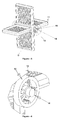
Figure 2 is an overall perspective view of the filtering unit. -
Figure 3 is an overall perspective view of the filtering unit from a different viewpoint. -
Figure 4 is an overall perspective view of the collector in the filtering unit. -
Figure 5 is an overall perspective view of the moving parts in the filtering unit. -
Figure 6 is a perspective view of the detail "D" shown inFigure 5 . - The parts in the drawings are individually enumerated and corresponding terms of these reference numbers are as follows.
Machine (A) Vessel (1) Filtering unit (2) Condenser (3) Air blowing unit (4) Heating unit (5) Water discharge (6) Air inlet (7) Air outlet (8) Water inlet (9) Body (10) Collector (11) Rotation axis (12) Mesh (13) Fixed adjustment part (14) Moving adjustment part (15) Shaft (16) -
Figure 1 shows a schematic view of the interior of a laundry drying machine of the invention (A). The machine (A) comprises a vessel (1) in which the laundry to be dried are placed (laundry is usually placed in a drum in the vessel -not shown-); at least one heating unit (5) where the air to be sent into the vessel (1) is heated; at least one air blowing unit (4) which circulates the air in the machine (A); at least one condenser (3) where the humid air discharged from the vessel (1) is dehumidified; at least one filtering unit (2) where all the foreign materials such as lint, fluff etc. in the circulating air is collected. A machine (A) is developed wherein said foreign materials are reliably collected by means of the filtering unit (2) details of which are disclosed below. - As mentioned above, the filtering unit (2) purges the air discharged from the vessel (1) of the foreign materials. Although the unit (2) is disposed at the exit of the vessel as illustrated in
Figure 1 , the unit (2) may be disposed elsewhere. However, the unit (2) is preferably disposed at the exit of the vessel (1) in order to protect other parts and units in the machine. -
Figure 2-6 show details of the filtering unit (2). The filtering unit (2) is provided with at least one air inlet (7); at least one air outlet (8); and at least one collector (11) in the body (10). The foreign materials in the air, which come from the air inlet (7) and enter into the unit (2), are caught by said collector (11); and the cleaned air moves from the air outlet (8) towards the other parts in the machine (A). - A further feature of the unit (2) is that the collector (11) can be cleaned on demand by the water coming from at least one water inlet (9). With the pressure of the water coming from the part (9), water is sent into the unit (2), forcing the accumulated foreign materials to leave the collector. The water entering into the unit (2) (together with the foreign materials) is discharged through at least one discharge (6).
-
Figures 4 and5 show details of an exemplary collector (11) utilized by the unit (2). The collector (11) comprises at least two meshes (13) (four meshes are shown in the figures) rotatable around an axis (12), which are disposed at certain angles with respect to one another. When one mesh (13) is filled with foreign materials, the other clean mesh (13) can be used thanks to the fact that the collector (11) is rotatable. - Rotation of the collector (11) is ensured by the air entering into the unit (2). As a result of the fact that a mesh (13) standing in the air flow direction is filled, the air moving towards this mesh (13) rotates the collector (11), which result in that the other mesh (13) (cleaned) becomes usable in the air flow direction. As mentioned above, the mesh (13) filled with foreign materials can be cleaned with water at this position it assumes.
- Adjustability of the angles of rotation of the collector (11) is crucial for more reliable operation of the invention. In an exemplary collector (11) shown in the figures, where four meshes (13) with right angles with one another are used; it is preferred that the mesh (13) standing in the air flow direction preferably rotates with a 90° degree angle after being filled so that another mesh (13) stands in the air flow direction.
- In other words, more reliable operation of the invention is ensured by the fact that the collector (11) remains steady until the mesh (13) that stands in the air flow direction is filled and that the collector then makes a 90° degree rotation. At least one fixed adjustment part (14) and at least one moving adjustment part (15) associated with the collector (11) are developed for this purpose.
- The moving adjustment part (15) is fixed on the collector (11) (may be connected to the shaft (16) of the collector (11), for instance) and rotates together with the collector (11). The fixed adjustment part (14) on the other hand is used for ensuring that the moving adjustment part (15) (therefore the collector (11)) is stopped and positioned at certain angles.
- Recessions and protrusions, which contact with one another, are provided on the moving adjustment part (15) and the fixed adjustment part (14). Owing to the flexibility of the moving adjustment part (14) and / or the fixed adjustment part (14) (these parts (14, 15) may be partially or wholly flexible), said recessions and protrusions can remain engaged to one another (with the rotation of the collector (11)) at certain angles until the mesh (13) is filled.
- As the mesh (13) is filled, recessions and / or protrusions disengage from one another and allow rotation of the collector (11). During this rotation, recessions and protrusions are engaged again and remain engaged until the mesh (13) is filled again.
Claims (7)
- A machine (A) comprising:- a vessel (1) in which the laundry to be dried are placed;- at least one filtering unit (2) provided with at least one air inlet and air outlet (7, 8) and at least one collector (11) where foreign materials in the air discharged from the vessel (1) accumulate
the machine drying the laundry with the hot air blown into the vessel (1) characterized in that the collector (11) is rotatable around an axis (12) and comprises at least two meshes (13) disposed at certain angles with respect to one another. - A machine (A) according to Claim 1 characterized in that the unit (2) comprises at least one water inlet (9) through which water is sent to the collector (11).
- A machine (A) according to Claim 1 characterized in that the unit (2) comprises at least one water discharge (6).
- A machine (A) according to Claim 1 characterized in that, with the rotational movement of the collector (11), the meshes (13) periodically stands in the air flow direction.
- A machine (A) according to Claim 1 characterized in that the unit (2) comprises at least one fixed adjustment part (14) and at least one moving adjustment part (15) which rotates together with the collector (11) and engages to the fixed adjustment part at certain angles.
- A machine (A) according to Claim 5 characterized in that said parts (14, 15) are provided with recessions and protrusions which contact one another.
- A machine (A) according to Claim 6 characterized in that the fixed adjustment part (14) and the moving adjustment part (15) are flexible.
Applications Claiming Priority (1)
| Application Number | Priority Date | Filing Date | Title |
|---|---|---|---|
| TR2010/07913A TR201007913A2 (en) | 2010-09-28 | 2010-09-28 | A filter unit for drying machines. |
Publications (2)
| Publication Number | Publication Date |
|---|---|
| EP2439328A1 true EP2439328A1 (en) | 2012-04-11 |
| EP2439328B1 EP2439328B1 (en) | 2014-03-19 |
Family
ID=44799658
Family Applications (1)
| Application Number | Title | Priority Date | Filing Date |
|---|---|---|---|
| EP11182499.1A Not-in-force EP2439328B1 (en) | 2010-09-28 | 2011-09-23 | A filtering unit for drying machines |
Country Status (2)
| Country | Link |
|---|---|
| EP (1) | EP2439328B1 (en) |
| TR (1) | TR201007913A2 (en) |
Cited By (2)
| Publication number | Priority date | Publication date | Assignee | Title |
|---|---|---|---|---|
| ITTO20131101A1 (en) * | 2013-12-31 | 2015-07-01 | Indesit Co Spa | MACHINE WASHING MACHINE WITH CLEANING DEVICE FOR A DRYING AIR FILTER |
| ITTO20131099A1 (en) * | 2013-12-31 | 2015-07-01 | Indesit Co Spa | MACHINE WASHING MACHINE WITH PREVENTION SYSTEM FOR THE INTEGRATION OF AN AIR FILTER |
Citations (5)
| Publication number | Priority date | Publication date | Assignee | Title |
|---|---|---|---|---|
| US3085348A (en) * | 1957-01-23 | 1963-04-16 | Oxy Catalyst Inc | Lint remover for fabric dryer |
| US20080196268A1 (en) | 2007-02-20 | 2008-08-21 | Han-Yong Jung | Filter cleaning apparatus and ductless dryer implementing the same |
| DE102008057460A1 (en) * | 2008-11-14 | 2010-05-20 | Miele & Cie. Kg | Laundry treatment machine, particularly laundry dryer, has drum rotatably mounted in housing, feed opening locked with door, and blower, where heating device is provided for generating process air stream which flows through heat exchanger |
| WO2010071355A2 (en) | 2008-12-17 | 2010-06-24 | Lg Electronics Inc. | Dryer and foreign material removing apparatus thereof |
| US20100154241A1 (en) * | 2008-12-22 | 2010-06-24 | Seung Phyo Ahn | Dryer and foreign material removing apparatus thereof |
-
2010
- 2010-09-28 TR TR2010/07913A patent/TR201007913A2/en unknown
-
2011
- 2011-09-23 EP EP11182499.1A patent/EP2439328B1/en not_active Not-in-force
Patent Citations (5)
| Publication number | Priority date | Publication date | Assignee | Title |
|---|---|---|---|---|
| US3085348A (en) * | 1957-01-23 | 1963-04-16 | Oxy Catalyst Inc | Lint remover for fabric dryer |
| US20080196268A1 (en) | 2007-02-20 | 2008-08-21 | Han-Yong Jung | Filter cleaning apparatus and ductless dryer implementing the same |
| DE102008057460A1 (en) * | 2008-11-14 | 2010-05-20 | Miele & Cie. Kg | Laundry treatment machine, particularly laundry dryer, has drum rotatably mounted in housing, feed opening locked with door, and blower, where heating device is provided for generating process air stream which flows through heat exchanger |
| WO2010071355A2 (en) | 2008-12-17 | 2010-06-24 | Lg Electronics Inc. | Dryer and foreign material removing apparatus thereof |
| US20100154241A1 (en) * | 2008-12-22 | 2010-06-24 | Seung Phyo Ahn | Dryer and foreign material removing apparatus thereof |
Cited By (4)
| Publication number | Priority date | Publication date | Assignee | Title |
|---|---|---|---|---|
| ITTO20131101A1 (en) * | 2013-12-31 | 2015-07-01 | Indesit Co Spa | MACHINE WASHING MACHINE WITH CLEANING DEVICE FOR A DRYING AIR FILTER |
| ITTO20131099A1 (en) * | 2013-12-31 | 2015-07-01 | Indesit Co Spa | MACHINE WASHING MACHINE WITH PREVENTION SYSTEM FOR THE INTEGRATION OF AN AIR FILTER |
| WO2015101892A1 (en) * | 2013-12-31 | 2015-07-09 | Indesit Company S.P.A. | Washing/drying machine with cleaning device for a drying air filter |
| WO2015101890A1 (en) * | 2013-12-31 | 2015-07-09 | Indesit Company S.P.A. | Washing/drying machine with a system for preventing an air filter from getting clogged |
Also Published As
| Publication number | Publication date |
|---|---|
| TR201007913A2 (en) | 2010-12-21 |
| EP2439328B1 (en) | 2014-03-19 |
Similar Documents
| Publication | Publication Date | Title |
|---|---|---|
| EP2788540B1 (en) | Dryer | |
| EP2938777B1 (en) | A laundry dryer comprising a spraying device | |
| EP2764153B1 (en) | A laundry washing and drying machine comprising a condenser | |
| EP1645674B1 (en) | Washing machine and method of controlling the same | |
| EP2938776B1 (en) | A laundry dryer comprising a filter | |
| EP3135805B1 (en) | Laundry dryer | |
| JP2006255423A (en) | Household clothes drying machine with improved lint filter | |
| EP3392398B1 (en) | Laundry dryer | |
| JP4706571B2 (en) | Washing and drying machine | |
| KR20120134369A (en) | Clothes treating apparatus | |
| EP2439328A1 (en) | A filtering unit for drying machines | |
| JP2016165357A (en) | Clothes dryer | |
| WO2014177176A1 (en) | Air-cooled condenser laundry treatment machine with lint collecting means | |
| KR101769365B1 (en) | Washing machine | |
| WO2015074836A1 (en) | A laundry dryer | |
| WO2016173787A1 (en) | A laundry dryer | |
| EP3138952B1 (en) | A laundry dryer | |
| WO2019129399A1 (en) | A dryer comprising a filter | |
| WO2016139229A1 (en) | A laundry dryer | |
| JP5927417B2 (en) | Clothes dryer | |
| CN219862019U (en) | Clothes treating apparatus | |
| JP2013153931A (en) | Clothing drying machine | |
| KR101948918B1 (en) | Laundry drier | |
| KR20110123328A (en) | dryer | |
| JP2013153933A (en) | Clothing drying machine |
Legal Events
| Date | Code | Title | Description |
|---|---|---|---|
| AK | Designated contracting states |
Kind code of ref document: A1 Designated state(s): AL AT BE BG CH CY CZ DE DK EE ES FI FR GB GR HR HU IE IS IT LI LT LU LV MC MK MT NL NO PL PT RO RS SE SI SK SM TR |
|
| AX | Request for extension of the european patent |
Extension state: BA ME |
|
| PUAI | Public reference made under article 153(3) epc to a published international application that has entered the european phase |
Free format text: ORIGINAL CODE: 0009012 |
|
| 17P | Request for examination filed |
Effective date: 20121009 |
|
| GRAP | Despatch of communication of intention to grant a patent |
Free format text: ORIGINAL CODE: EPIDOSNIGR1 |
|
| INTG | Intention to grant announced |
Effective date: 20131118 |
|
| GRAS | Grant fee paid |
Free format text: ORIGINAL CODE: EPIDOSNIGR3 |
|
| GRAA | (expected) grant |
Free format text: ORIGINAL CODE: 0009210 |
|
| AK | Designated contracting states |
Kind code of ref document: B1 Designated state(s): AL AT BE BG CH CY CZ DE DK EE ES FI FR GB GR HR HU IE IS IT LI LT LU LV MC MK MT NL NO PL PT RO RS SE SI SK SM TR |
|
| REG | Reference to a national code |
Ref country code: GB Ref legal event code: FG4D |
|
| REG | Reference to a national code |
Ref country code: CH Ref legal event code: EP |
|
| REG | Reference to a national code |
Ref country code: IE Ref legal event code: FG4D |
|
| REG | Reference to a national code |
Ref country code: AT Ref legal event code: REF Ref document number: 657776 Country of ref document: AT Kind code of ref document: T Effective date: 20140415 |
|
| REG | Reference to a national code |
Ref country code: DE Ref legal event code: R096 Ref document number: 602011005447 Country of ref document: DE Effective date: 20140424 |
|
| PG25 | Lapsed in a contracting state [announced via postgrant information from national office to epo] |
Ref country code: NO Free format text: LAPSE BECAUSE OF FAILURE TO SUBMIT A TRANSLATION OF THE DESCRIPTION OR TO PAY THE FEE WITHIN THE PRESCRIBED TIME-LIMIT Effective date: 20140619 Ref country code: LT Free format text: LAPSE BECAUSE OF FAILURE TO SUBMIT A TRANSLATION OF THE DESCRIPTION OR TO PAY THE FEE WITHIN THE PRESCRIBED TIME-LIMIT Effective date: 20140319 |
|
| REG | Reference to a national code |
Ref country code: NL Ref legal event code: VDEP Effective date: 20140319 |
|
| REG | Reference to a national code |
Ref country code: AT Ref legal event code: MK05 Ref document number: 657776 Country of ref document: AT Kind code of ref document: T Effective date: 20140319 |
|
| REG | Reference to a national code |
Ref country code: LT Ref legal event code: MG4D |
|
| PG25 | Lapsed in a contracting state [announced via postgrant information from national office to epo] |
Ref country code: CY Free format text: LAPSE BECAUSE OF FAILURE TO SUBMIT A TRANSLATION OF THE DESCRIPTION OR TO PAY THE FEE WITHIN THE PRESCRIBED TIME-LIMIT Effective date: 20140319 Ref country code: SE Free format text: LAPSE BECAUSE OF FAILURE TO SUBMIT A TRANSLATION OF THE DESCRIPTION OR TO PAY THE FEE WITHIN THE PRESCRIBED TIME-LIMIT Effective date: 20140319 Ref country code: FI Free format text: LAPSE BECAUSE OF FAILURE TO SUBMIT A TRANSLATION OF THE DESCRIPTION OR TO PAY THE FEE WITHIN THE PRESCRIBED TIME-LIMIT Effective date: 20140319 |
|
| PG25 | Lapsed in a contracting state [announced via postgrant information from national office to epo] |
Ref country code: LV Free format text: LAPSE BECAUSE OF FAILURE TO SUBMIT A TRANSLATION OF THE DESCRIPTION OR TO PAY THE FEE WITHIN THE PRESCRIBED TIME-LIMIT Effective date: 20140319 Ref country code: RS Free format text: LAPSE BECAUSE OF FAILURE TO SUBMIT A TRANSLATION OF THE DESCRIPTION OR TO PAY THE FEE WITHIN THE PRESCRIBED TIME-LIMIT Effective date: 20140319 Ref country code: HR Free format text: LAPSE BECAUSE OF FAILURE TO SUBMIT A TRANSLATION OF THE DESCRIPTION OR TO PAY THE FEE WITHIN THE PRESCRIBED TIME-LIMIT Effective date: 20140319 |
|
| PG25 | Lapsed in a contracting state [announced via postgrant information from national office to epo] |
Ref country code: CZ Free format text: LAPSE BECAUSE OF FAILURE TO SUBMIT A TRANSLATION OF THE DESCRIPTION OR TO PAY THE FEE WITHIN THE PRESCRIBED TIME-LIMIT Effective date: 20140319 Ref country code: RO Free format text: LAPSE BECAUSE OF FAILURE TO SUBMIT A TRANSLATION OF THE DESCRIPTION OR TO PAY THE FEE WITHIN THE PRESCRIBED TIME-LIMIT Effective date: 20140319 Ref country code: NL Free format text: LAPSE BECAUSE OF FAILURE TO SUBMIT A TRANSLATION OF THE DESCRIPTION OR TO PAY THE FEE WITHIN THE PRESCRIBED TIME-LIMIT Effective date: 20140319 Ref country code: BG Free format text: LAPSE BECAUSE OF FAILURE TO SUBMIT A TRANSLATION OF THE DESCRIPTION OR TO PAY THE FEE WITHIN THE PRESCRIBED TIME-LIMIT Effective date: 20140619 Ref country code: EE Free format text: LAPSE BECAUSE OF FAILURE TO SUBMIT A TRANSLATION OF THE DESCRIPTION OR TO PAY THE FEE WITHIN THE PRESCRIBED TIME-LIMIT Effective date: 20140319 Ref country code: BE Free format text: LAPSE BECAUSE OF FAILURE TO SUBMIT A TRANSLATION OF THE DESCRIPTION OR TO PAY THE FEE WITHIN THE PRESCRIBED TIME-LIMIT Effective date: 20140319 Ref country code: IS Free format text: LAPSE BECAUSE OF FAILURE TO SUBMIT A TRANSLATION OF THE DESCRIPTION OR TO PAY THE FEE WITHIN THE PRESCRIBED TIME-LIMIT Effective date: 20140719 |
|
| PG25 | Lapsed in a contracting state [announced via postgrant information from national office to epo] |
Ref country code: PL Free format text: LAPSE BECAUSE OF FAILURE TO SUBMIT A TRANSLATION OF THE DESCRIPTION OR TO PAY THE FEE WITHIN THE PRESCRIBED TIME-LIMIT Effective date: 20140319 Ref country code: AT Free format text: LAPSE BECAUSE OF FAILURE TO SUBMIT A TRANSLATION OF THE DESCRIPTION OR TO PAY THE FEE WITHIN THE PRESCRIBED TIME-LIMIT Effective date: 20140319 Ref country code: ES Free format text: LAPSE BECAUSE OF FAILURE TO SUBMIT A TRANSLATION OF THE DESCRIPTION OR TO PAY THE FEE WITHIN THE PRESCRIBED TIME-LIMIT Effective date: 20140319 Ref country code: SK Free format text: LAPSE BECAUSE OF FAILURE TO SUBMIT A TRANSLATION OF THE DESCRIPTION OR TO PAY THE FEE WITHIN THE PRESCRIBED TIME-LIMIT Effective date: 20140319 |
|
| REG | Reference to a national code |
Ref country code: DE Ref legal event code: R097 Ref document number: 602011005447 Country of ref document: DE |
|
| PG25 | Lapsed in a contracting state [announced via postgrant information from national office to epo] |
Ref country code: PT Free format text: LAPSE BECAUSE OF FAILURE TO SUBMIT A TRANSLATION OF THE DESCRIPTION OR TO PAY THE FEE WITHIN THE PRESCRIBED TIME-LIMIT Effective date: 20140721 |
|
| PLBE | No opposition filed within time limit |
Free format text: ORIGINAL CODE: 0009261 |
|
| STAA | Information on the status of an ep patent application or granted ep patent |
Free format text: STATUS: NO OPPOSITION FILED WITHIN TIME LIMIT |
|
| PG25 | Lapsed in a contracting state [announced via postgrant information from national office to epo] |
Ref country code: DK Free format text: LAPSE BECAUSE OF FAILURE TO SUBMIT A TRANSLATION OF THE DESCRIPTION OR TO PAY THE FEE WITHIN THE PRESCRIBED TIME-LIMIT Effective date: 20140319 |
|
| PGFP | Annual fee paid to national office [announced via postgrant information from national office to epo] |
Ref country code: DE Payment date: 20141129 Year of fee payment: 4 |
|
| 26N | No opposition filed |
Effective date: 20141222 |
|
| PG25 | Lapsed in a contracting state [announced via postgrant information from national office to epo] |
Ref country code: IT Free format text: LAPSE BECAUSE OF FAILURE TO SUBMIT A TRANSLATION OF THE DESCRIPTION OR TO PAY THE FEE WITHIN THE PRESCRIBED TIME-LIMIT Effective date: 20140319 |
|
| REG | Reference to a national code |
Ref country code: DE Ref legal event code: R097 Ref document number: 602011005447 Country of ref document: DE Effective date: 20141222 |
|
| PG25 | Lapsed in a contracting state [announced via postgrant information from national office to epo] |
Ref country code: MC Free format text: LAPSE BECAUSE OF FAILURE TO SUBMIT A TRANSLATION OF THE DESCRIPTION OR TO PAY THE FEE WITHIN THE PRESCRIBED TIME-LIMIT Effective date: 20140319 Ref country code: LU Free format text: LAPSE BECAUSE OF FAILURE TO SUBMIT A TRANSLATION OF THE DESCRIPTION OR TO PAY THE FEE WITHIN THE PRESCRIBED TIME-LIMIT Effective date: 20140923 |
|
| REG | Reference to a national code |
Ref country code: CH Ref legal event code: PL |
|
| REG | Reference to a national code |
Ref country code: IE Ref legal event code: MM4A |
|
| REG | Reference to a national code |
Ref country code: FR Ref legal event code: ST Effective date: 20150529 |
|
| PG25 | Lapsed in a contracting state [announced via postgrant information from national office to epo] |
Ref country code: SI Free format text: LAPSE BECAUSE OF FAILURE TO SUBMIT A TRANSLATION OF THE DESCRIPTION OR TO PAY THE FEE WITHIN THE PRESCRIBED TIME-LIMIT Effective date: 20140319 Ref country code: LI Free format text: LAPSE BECAUSE OF NON-PAYMENT OF DUE FEES Effective date: 20140930 Ref country code: CH Free format text: LAPSE BECAUSE OF NON-PAYMENT OF DUE FEES Effective date: 20140930 |
|
| PG25 | Lapsed in a contracting state [announced via postgrant information from national office to epo] |
Ref country code: IE Free format text: LAPSE BECAUSE OF NON-PAYMENT OF DUE FEES Effective date: 20140923 Ref country code: FR Free format text: LAPSE BECAUSE OF NON-PAYMENT OF DUE FEES Effective date: 20140930 |
|
| REG | Reference to a national code |
Ref country code: DE Ref legal event code: R119 Ref document number: 602011005447 Country of ref document: DE |
|
| PG25 | Lapsed in a contracting state [announced via postgrant information from national office to epo] |
Ref country code: SM Free format text: LAPSE BECAUSE OF FAILURE TO SUBMIT A TRANSLATION OF THE DESCRIPTION OR TO PAY THE FEE WITHIN THE PRESCRIBED TIME-LIMIT Effective date: 20140319 |
|
| GBPC | Gb: european patent ceased through non-payment of renewal fee |
Effective date: 20150923 |
|
| PG25 | Lapsed in a contracting state [announced via postgrant information from national office to epo] |
Ref country code: GR Free format text: LAPSE BECAUSE OF FAILURE TO SUBMIT A TRANSLATION OF THE DESCRIPTION OR TO PAY THE FEE WITHIN THE PRESCRIBED TIME-LIMIT Effective date: 20140620 Ref country code: MT Free format text: LAPSE BECAUSE OF FAILURE TO SUBMIT A TRANSLATION OF THE DESCRIPTION OR TO PAY THE FEE WITHIN THE PRESCRIBED TIME-LIMIT Effective date: 20140319 |
|
| PG25 | Lapsed in a contracting state [announced via postgrant information from national office to epo] |
Ref country code: HU Free format text: LAPSE BECAUSE OF FAILURE TO SUBMIT A TRANSLATION OF THE DESCRIPTION OR TO PAY THE FEE WITHIN THE PRESCRIBED TIME-LIMIT; INVALID AB INITIO Effective date: 20110923 Ref country code: TR Free format text: LAPSE BECAUSE OF FAILURE TO SUBMIT A TRANSLATION OF THE DESCRIPTION OR TO PAY THE FEE WITHIN THE PRESCRIBED TIME-LIMIT Effective date: 20140319 Ref country code: GB Free format text: LAPSE BECAUSE OF NON-PAYMENT OF DUE FEES Effective date: 20150923 Ref country code: DE Free format text: LAPSE BECAUSE OF NON-PAYMENT OF DUE FEES Effective date: 20160401 |
|
| PG25 | Lapsed in a contracting state [announced via postgrant information from national office to epo] |
Ref country code: MK Free format text: LAPSE BECAUSE OF FAILURE TO SUBMIT A TRANSLATION OF THE DESCRIPTION OR TO PAY THE FEE WITHIN THE PRESCRIBED TIME-LIMIT Effective date: 20140319 |
|
| PG25 | Lapsed in a contracting state [announced via postgrant information from national office to epo] |
Ref country code: AL Free format text: LAPSE BECAUSE OF FAILURE TO SUBMIT A TRANSLATION OF THE DESCRIPTION OR TO PAY THE FEE WITHIN THE PRESCRIBED TIME-LIMIT Effective date: 20140319 |